


PROPRIETARY NOTICE AND LIABILITY DISCLAIMER
The information disclosed in this document, including all designs and related
materials, is the valuable property of NEC Computer Systems Division, Packard
Bell NEC (NECCSD, PBNEC) and/or its licensors. NECCSD and/or its licensors,
as appropriate, reserve all patent, copyright and other proprietary rights to this
document, including all design, manufacturin g, reproduction, use, and sales rights
thereto, except to the extent said rights are expressly granted to others.
The NECCSD product(s) discussed in this document are warranted in accordance
with the terms of the Warr anty Statement accompanying each product. However,
actual performance of each such product is dependent upon factors such as system
configuration, customer data, and operator control. Since implementation by
customers of each product may vary, the suitability of specific product
configurations and applications must be determined by the customer and is not
warranted by NECCSD.
To allow for design and specification improvements, the information in this
document is subject to change at any time, without notice. Reproduction of this
document or portions thereof without prior written approval of NECCSD is
prohibited.
NEC is a registered trademark of NEC Corporation and NEC PowerMate and MultiSync are registered
trademarks of NEC Technologies, Inc. These registered trademarks are used under license by Packard
Bell NEC, Inc.
MS-DOS and Windows are registered trademarks of Microsoft Corporation.
All other product, brand, or trade names used in this publication are the trademarks or registered
trademarks of their respective trademark owners.
First Printing — April 1997
Copyright 1997
NEC Computer Systems Division
Packard Bell NEC, Inc.
1414 Massachusetts Avenue
Boxborough, MA 01719
All Rights Reserved

Contents
Using This Guide
Text Conventions...................................................... x
Related Documents ................................................... xi
1 Introducing Your Computer
Front Features .......................................................... 1-2
System Controls and Lamps................................. 1-3
Diskette Drive A.................................................. 1-5
CD-ROM Reader................................................. 1-6
Back Features........................................................... 1-8
External Connectors............................................. 1-9
Power Supply Features ........................................ 1-11
Speakers................................................................... 1-12
Microphone .............................................................. 1-13
2 Getting Started
Using a Mouse.......................................................... 2-1
About Your Online Documentation ........................... 2-2
Where to Go from Here............................................. 2-4
3 Installing Options
Option Installation Procedures .................................. 3-2
Safety Precautions ............................................... 3-4
Removing the System Unit Cover......................... 3-5
Replacing the System Unit Cover......................... 3-7
Expansion Boards..................................................... 3-8
Locating Expansion Slots..................................... 3-8
Installing an Expansion Board.............................. 3-10
Installing an Expansion Board in the Inside Slot ... 3-12
Removing an Expansion Board ............................ 3-14
Removing an Expansion Board from Inside Slot ... 3-15
Contents iii

SIMM Upgrade ........................................................ 3-17
Checking System Memory.................................... 3-18
Removing a SIMM .............................................. 3-20
Installing a SIMM ............................................... 3-21
Video Upgrade.......................................................... 3-22
Processor Upgrade.................................................... 3-24
Removing the Processor....................................... 3-24
Installing the Processor ........................................ 3-25
Data Storage Devices................................................ 3-26
Locating Device Slots .......................................... 3-26
Preparing the Device............................................ 3-27
Device Cables...................................................... 3-28
Diskette Drive Signal Cable ............................ 3-29
IDE Signal Cables .......................................... 3-30
System Power Cables...................................... 3-31
Cabling Storage Devices ...................................... 3-31
Cabling an IDE Device ................................... 3-32
Cabling a Diskette Drive................................. 3-33
Installing Storage Devices.................................... 3-34
Removing the 3 1/2-Inch Drive Bracket........... 3-34
3 1/2-Inch Drive Installation ........................... 3-36
Removing the Front Panel ............................... 3-37
Installing the 5 1/4-Inch Device....................... 3-38
Replacing the Front Panel ............................... 3-41
Replacing the 3 1/2-Inch Drive Bracket........... 3-42
Adding External Options...................................... 3-43
Connecting a Parallel Printer........................... 3-43
Connecting an RS-232C Device ...................... 3-44
iv Contents

4 Setting System Parameters
The Setup Utility ...................................................... 4-2
How to Start Setup ................................................... 4-3
How to Use Setup..................................................... 4-4
The Menu Bar ..................................................... 4-5
The Legend Bar ................................................... 4-6
Selecting a Menu Item..................................... 4-7
Displaying a Submenu .................................... 4-7
Getting Help ................................................... 4-7
Main Menu Options.................................................. 4-7
IDE Adapters....................................................... 4-9
Memory Cache .................................................... 4-11
Memory Shadow.................................................. 4-12
Boot Options ....................................................... 4-12
NumLock ............................................................ 4-13
The Advanced Menu................................................. 4-14
Integrated Peripherals Menu................................. 4-15
The Security Menu ................................................... 4-17
The Power Menu ...................................................... 4-20
The Boot Menu......................................................... 4-22
The Exit Menu.......................................................... 4-22
Save Changes & Exit........................................... 4-22
Discard Changes & Exit ...................................... 4-23
Get Default Values .............................................. 4-23
Load Previous Values .......................................... 4-24
Save Changes ...................................................... 4-24
Restoring System Software ....................................... 4-24
System Restore Options ....................................... 4-25
Restore Individual Files........................................ 4-26
Selecting Files................................................. 4-27
Checking Selected Files................................... 4-27
Restoring the Files ............................................... 4-28
System Recovery ................................................. 4-29
Contents v

5 Setting System Board Jumpers
Changing Processor Jumper Settings ......................... 5-2
Clearing Your Password ........................................... 5-5
6 Using Voyetra Sound Software
Power Bar ................................................................ 6-2
Audio Mixer............................................................. 6-3
Adjusting the Sound with Software....................... 6-3
Adjusting the Sound with Speakers....................... 6-4
CD Player................................................................. 6-4
WAV Player............................................................. 6-4
Recording Digital Audio Files .............................. 6-5
Playing Digital Audio Files .................................. 6-5
Editing Digital Audio Files................................... 6-6
MIDI Player ............................................................. 6-6
7 If You Have a Problem
Problem Checklist..................................................... 7-2
Solutions to Common Problems................................. 7-3
System Problems ................................................. 7-3
Diskette Drive Problems ...................................... 7-5
Monitor Problems................................................ -6
Keyboard/Mouse Problems .................................. 7-7
CD-ROM Problems ............................................. 7-7
Speaker Problems ................................................ 7-8
Microphone Problems .......................................... 7-8
Replacing the CMOS Battery.................................... 7-9
Diagnostic Diskette................................................... 7-12
Getting Technical Help ............................................. 7-12
vi Contents

A Setting Up a Healthy Work Environment
Making Your Computer Work for You...................... A-1
Arrange Your Equipment .......................................... A-3
Adjust Your Chair .................................................... A-4
Adjust Your Input Devices........................................ A-6
Adjust Your Monitor ................................................ A-9
Vary Your Workday ................................................. A-11
Pre-Existing Conditions and Psychosocial Factors..... A-12
Checking Your Comfort: How Do You Measure Up? A-13
Checking Your Chair ........................................... A-13
Checking Your Keyboard..................................... A-13
Checking Your Mouse ......................................... A-13
Checking Your Monitor ....................................... A-13
Checking You...................................................... A-14
B Reviewing System Interrupts
Interrupt Controller................................................... B-1
C Limited Warranty
How Long Is the Warranty........................................ C-1
Who Is Protected?..................................................... C-1
What Is Covered and What Is Not Covered ............... C-1
What We Will Pay For and What We Will Not
Pay For ................................................................ C-3
How You Can Get Warranty Service......................... C-3
Limitation of Damages and Implied Warranties ......... C-4
How State Law Relates to the Warranty.................... C-4
For Warranty Information......................................... C-5
Contents vii

List of Tables
Index
Quick Reference to Information About Your Computer 2-5
Setup Key Functions................................................. 4-6
Main Menu Parameters............................................. 4-8
IDE Hard Disk Parameters........................................ 4-11
Memory Cache Parameters ....................................... 4-12
Boot Option Parameters............................................ 4-13
Keyboard Features Parameters.................................. 4-14
Advanced Menu Parameters...................................... 4-15
Integrated Peripherals Parameters ............................. 4-16
System Security Options........................................... 4-19
Power Management Parameters................................. 4-21
Interrupt Level Assignments...................................... B-1
viii Contents

Using This Guide
The PowerMate Ve ETC Series User's Guide provides a
quick reference to information about your computer.
The guide contains the following information:
Chapter 1, Introducing Your Computer, provides a look
at system components. See this chapter to familiarize
yourself with your system.
Chapter 2, Getting Started, gives you information about
using a mouse, using online documentation, and what
you should do after your system is up and running.
The chapter includes a quick-reference chart for finding
information about a variety topics.
Chapter 3, Installing Options, provides installation
procedures for internal and external options.
Chapter 4, Setting System Parameters, describes the
Setup utility and explains how to use it to configure your
system.
Chapter 5, Setting System Board Jumpers, provides
information on changing jumper settings when
reconfiguring your system.
Chapter 6, Using Voyetra Sound Software, explains how
to use Voyetra
®
’s Multimedia Sound Software to play
music CDs, record, play and edit audio files, and play
and edit MIDI files.
Chapter 7, If You Have a Problem, contains
troubleshooting tips for solving simple problems and
provides information on where you can find help when
you cannot solve a problem yourself.
Using This Guide ix
Appendix A, Setting Up a Healthy Work Environment,
contains guidelines to help you use your computer
productively and safely. This appendix also instructs
you on how to set up and use your computer to reduce
your risk of developing nerve, muscle, or tendon
disorders.
Appendix B, Reviewing System Interrupts, provides the
interrupt settings used by the system.
Appendix C, Limited Warranty, includes warranty
information about your PowerMate
Desktop Computer.
!
Prolonged or improper use of a computer
workstation may pose a risk of serious injury. To
reduce your risk of injury, set up and use your
computer in the manner described in Appendix A,
Setting Up a Healthy Work Environment.
WARNING
®
Ve ETC Series
TEXT CONVENTIONS
This guide uses the following text conventions.
Warnings, cautions, and notes have the following
meanings:
W arnings alert you t o situations that coul d result in
serious personal injury or loss of life.
x Using This Guide
!
WARNING
Cautions indicate situations that can damage the
hardware or software.
NOTE
Notes give important information about the
material being described.
Names of keyboard keys are printed as they appear on
the keyboard, for example,
Text or keystrokes that you enter appear in boldface
type. For example, type
File names are printed in uppercase letters.
RELATED DOCUMENTS
In addition to this guide, the following printed
documentation ships with your PowerMate Ve ETC Series
system. See the NEC PowerMate Customers Catalog
included with your system for other related documentation.
!
CAUTION
Ctrl, Alt
return
, or
and press
Enter
Enter
.
.
NEC PowerMate Ve ETC Series Quick Setup/
Quick-Reference Roadmap
Quick Setup contains information for quickly getting
your system up and running. Read this information to set
up the system for the first time.
The Quick-Reference Roadmap gives you a look at the
documentation, NEC tools, software applications, and
services available to you.
Using This Guide xi

How Does Your Workplace Measure Up?
This brochure provides information for setting up and
using your computer productively and safely.
Information includes guidelines to reduce the risk of
injury associated with using a computer.
Windows® 95 User’s Guide
This guide is a quick reference to information about
using Windows 95.
Your system comes with the following online documentation
on the hard disk:
PowerMate Ve ETC Series System Documentation
This online documentation is your comprehensive source
of information about your system. It contains a System
Tour, User’s Guide, Product Information Center, Option
Installation Center, and Support Center.
Healthy Environment
This is an online version of the “How Does Your
Workplace Measure Up?” brochure.
Most of your application programs provide extensive online
help. Some programs provide separate online user’s guides
for specific applications.
Windows 95 provides extensive online help and “wizards”
to guide you through procedures.
xii Using This Guide
Using Windows 95
Contains information for using Windows 95.

Introducing Your
1
Computer
!
Prolonged or improper use of a computer
workstation may pose a risk or serious injury. To
reduce your risk of injury, set up and use your
computer in the manner described in Appendix A,
Setting Up a Healthy Work Environment.
After setting up your computer, familiarize yourself with
your system. The following sections provide a brief look at
the front and back features of your system.
For a comprehensive source of information about your
computer, see the online NEC PowerMate Ve ETC Series
System Documentation. The online documentation can be
accessed through NEC’s PowerMate Online Documents
group on the Windows 95 desktop.
WARNING
Introducing Your Computer 1-1
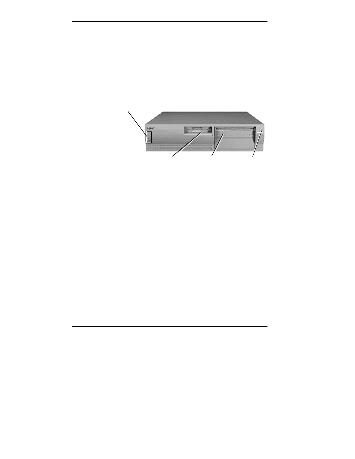
FRONT FEATURES
The following figure shows the features on the front of the
system. A brief description of the features follows the
figure.
System Controls
and Lamps
*Multimed ia syst ems on ly.
CD-ROM Reader*Diskette Drive A
Power
Button
Front features
1-2 Introducing Your Computer
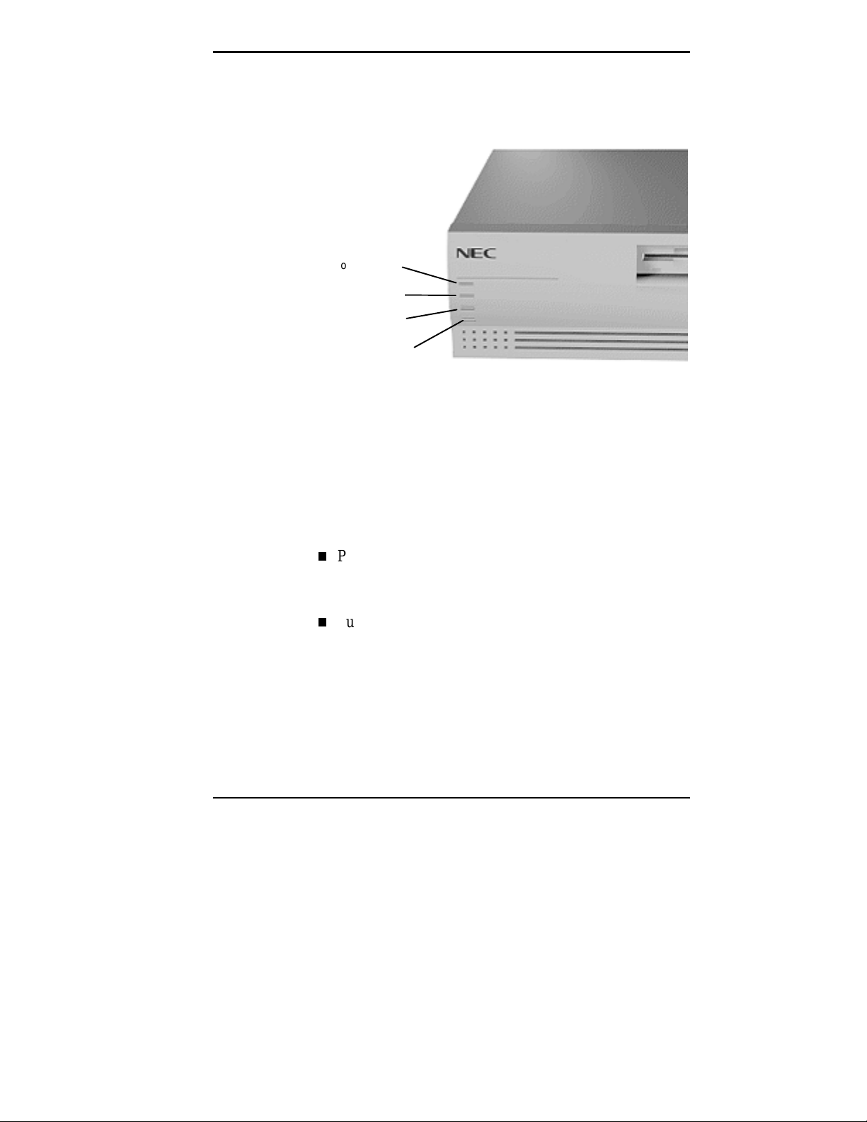
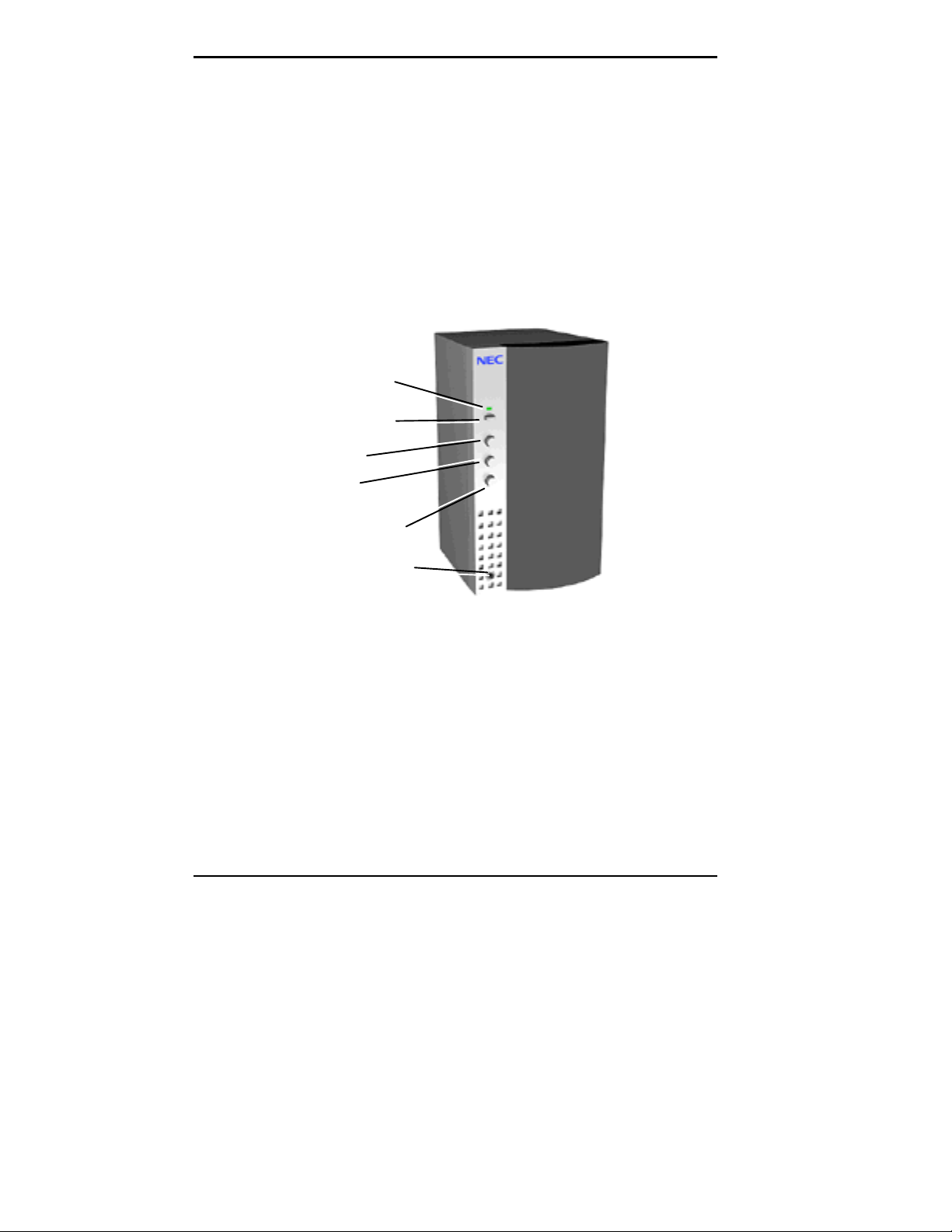
The following figure depicts in detail the system lamps and
controls called out in the previous figure.
Power Lamp
Disk La mp
Reset Button
Suspend Button
System Controls and Lamps
System controls let you select specific system operations.
Lamps let you know the status of system operation. Your
computer has the following controls and lamps:
System controls and lamps
Power button
Press this button to turn on system power. Press it again
to turn off the power.
Suspend button
Lets you initiate a power-saving mode of operating your
computer. Press this button to suspend system operation
when you plan to be away from your computer for a
short time. Press any key or move your mouse to resume
system operation to where you stopped it. See “The
Power Menu” in Chapter 4 for more information on the
Suspend operation.
Introducing Your Computer 1-3
A blinking system unit power lamp lets you know that
the system is in a power-saving mode.
Reset button
The reset button lets you manually restart your system
when it does not respond to keyboard commands.
!
Resetti ng your system can resul t i n t he loss of dat a.
Press the reset button only when all other methods
of restarting your computer fails.
Power lamp
The power lamp indicates whether system power is on or
off. It also lets you know if the system is operating in a
power-saving mode.
A steady green lamp indicates that the power is on to all
system components. A blinking green lamp indicates that
the system is in Suspend mode with full power
reduction.
CAUTION
Disk lamp
Indicates if your hard disk is doing anything. A green
lamp tells you that the hard disk is reading or writing
data.
Do not turn off the system, unless absolutely
necessary, while the di sk l amp is lit. To do so can
damage your hard disk or data.
1-4 Introducing Your Computer
!
CAUTION
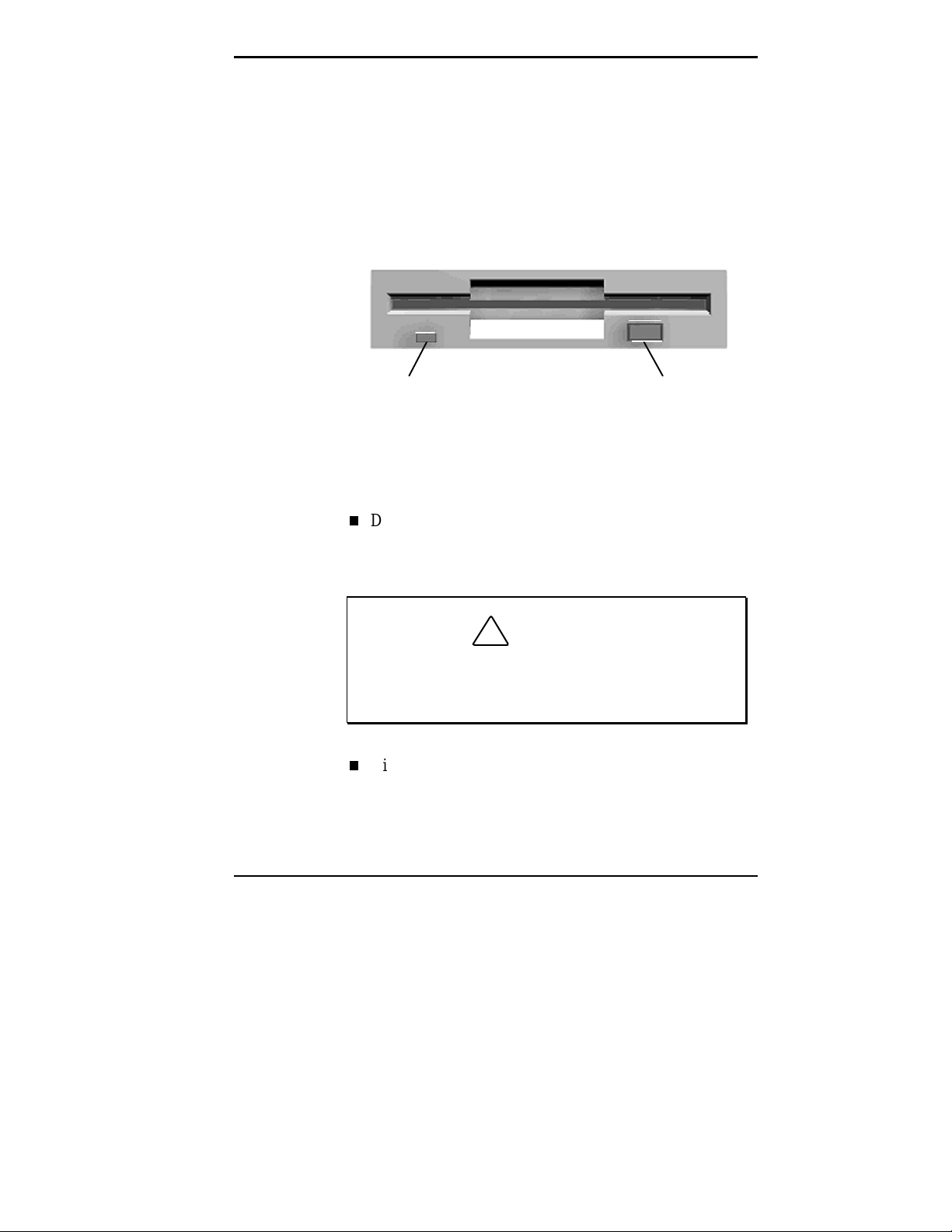
Diskette Drive A
Diskette drive A loads and starts programs from a diskette.
Diskette drive A is your primary “bootable” drive.
Busy Lamp
Your diskette drive has the following features:
Diskette drive busy lamp
Lights when your diskette drive is reading to or writing
from a diskette.
!
To prev ent damage to y our di skette dr iv e and data,
do not turn off the system or remove a diskette
while the diskette drive busy lamp is lit.
Diskette release button
Press this button to release a diskette from the diskette
drive.
CAUTION
Diskette Release ButtonDiskette Drive
Diskette drive A features
Introducing Your Computer 1-5
CD-ROM Reader
An eight-speed CD-ROM reader is a standard feature in
multimedia models. The CD-ROM reader is assigned as
drive F.
Use the CD-ROM reader to load and start programs from a
compact disc (CD). You can also use the CD-ROM reader
to play your audio CDs.
with a bootable CD. To enable the system to boot
from the CD-ROM, see “Boot Menu” in Chapter 4.
The CD-ROM reader operates at different speeds depending
on whether the CD you are using contains data or music.
This allows you to get your data faster and to see smoother
animation and video.
NOTE
You can boot your system f rom the CD- ROM
NOTE
The CD-ROM reader in your system might
look different from the one shown here.
1-6 Introducing Your Computer

CD Tray
Headphone
Jack
CD Busy
Lamp
Volume
Control Knob
Emergency
Eject Hol e
Open/Close
Button
CD-ROM reader features
The CD-ROM reader has the following features:
Headphone jack
Allows the connection of an optional set of headphones
with a stereo mini-jack plug.
Volume control knob
Lets you adjust the volume of an optional set of
headphones.
Open/close button
Opens or closes the reader’s loading tray. Press this
button when the computer power is on to insert or
remove a CD into or out of the reader.
Emergency eject hole
Allows the manual ejection of a CD if the eject function
is disabled by software or if a power failure occurs.
Introducing Your Computer 1-7
CD busy lamp
Lights when the reader is retrieving data, music, or
graphics/audio from a CD. Do not eject the CD or turn
off the system unit when the lamp is on.
CD tray
Provides a surface for loading a CD into the reader.
Press the open/close button to open or close the CD tray.
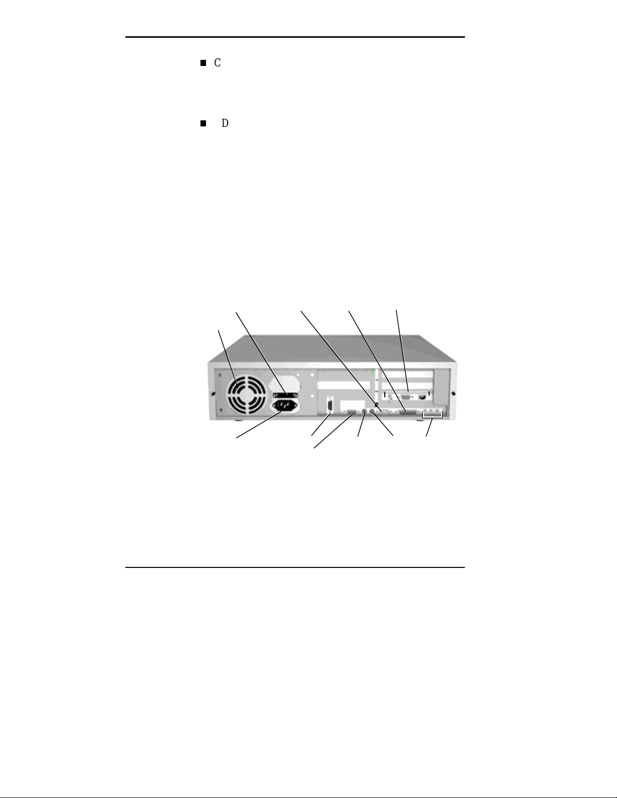
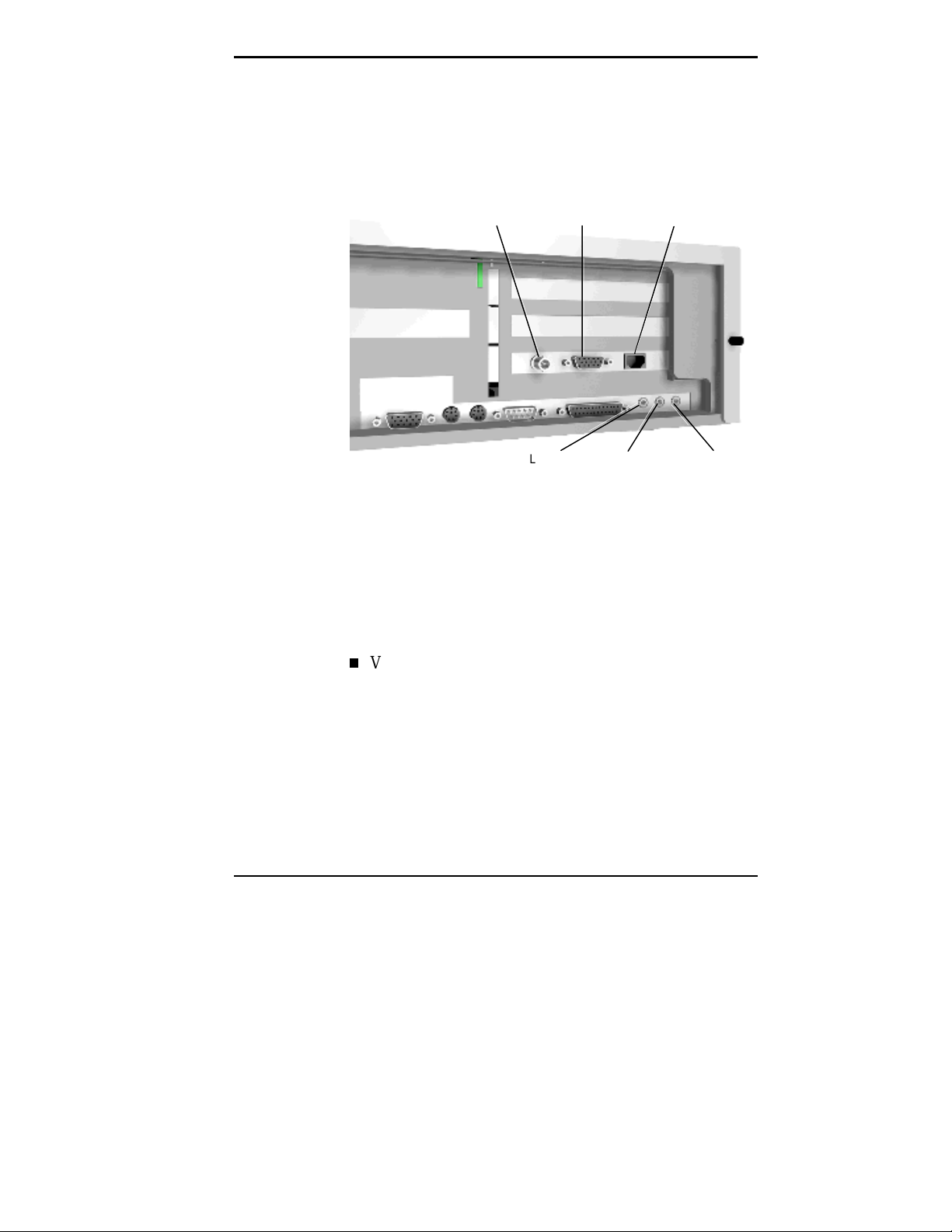
BACK FEATURES
On the back of your computer, you’ll find external
connectors, power supply features, and expansion board
slots. The following figures show these features. (The slot
location of the network board in your system might vary
from the slot location shown in the figures.)
Voltage Selector
Switch
Fan
Power
Socket
*Multimedia
Syst ems Only
1-8 Introducing Your Computer
Serial
Port 1
Seria l Port 2
VGA Monitor
Connector
Printer
Port
Keyboard
Port
Network Board
Connectors
Mouse
Port
Audio
Connectors*
Rear features
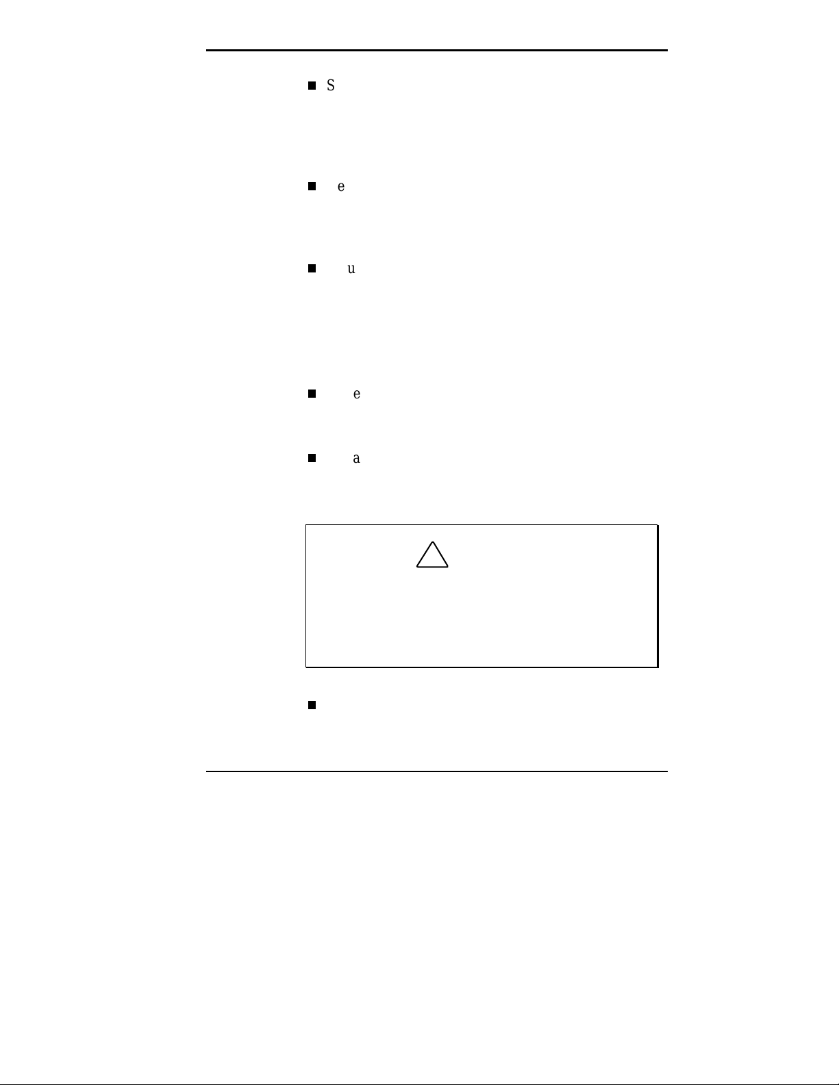
The following figure identifies the audio connectors
(multimedia systems only) and network board connectors
called out in the previous figure.
External Connectors
External connectors let you attach peripheral devices, such
as a monitor, keyboard, mouse, and printer to your system.
Your system has the following external connectors:
BNC
Connector
Line In
Jack
AUI
Connector
Microphone
In Jack
RJ-45
Connector
Audio and network board connectors
Line Out
Jack
VGA monitor connector
Attach the signal cable from your monitor to this
®
connector. Supports an NEC MultiSync
monitor or
other video graphics array (VGA)-compatible monitor
with a 15-pin connector.
Introducing Your Computer 1-9

Audio connectors
These connectors come integrated on multimedia models.
The connectors include microphone in, line in, and line
out jacks.
The microphone in jack lets you connect a
microphone for recording audio information in your
data system files.
The line in jack lets you connect a stereo audio
device such as a stereo amplifier or a cassette or
minidisc player for playback or recording.
The line out jack allows you to connect an amplified
output device such as powered speakers, stereo tape
recorder, or an external amplifier for audio output.
Use this jack to connect the stereo speakers that
come with your system.
{ XE "Network board connectors" }Network board
connectors
These connectors allow connection to an Ethernet
network and communications with other computers. The
board has three connectors for coaxial and twisted-pair
network cabling.
The BNC connector supports thin coaxial cables.
The AUI connector supports thick coaxial cables.
The RJ-45 connector supports twisted-pair
10BASE-T cables.
Printer Port
Use this port to connect a parallel printer with a 25-pin
connector to the system. The enhanced printer port
supports Enhanced Capabilities Port (ECP) and
Enhanced Parallel Port (EPP) modes.
1-10 Introducing Your Computer
Serial Ports
Attach a serial device with a 9-pin connector to each
serial port. Serial devices include a pointing device,
serial printer, or modem. The buffered high-speed serial
port supports transfer rates of up to 19.2 KB per second.
Keyboard port
Attach your keyboard to this connector. The keyboard
port supports a personal system (PS)/2
keyboard with a 6-pin mini DIN connector.
Mouse port
Attach your mouse to this port. The mouse port supports
a PS/2-compatible mouse.
Power Supply Features
Your system has the following power supply features:
Power supply fan
Keep this area clear for proper ventilation. The power
supply fan cools system components.
Voltage selector switch
Sets the voltage for your system to 115 volts or
240 volts.
®
-compatible
!
Set the switch correctl y f or the v olt age in your ar ea.
Most wall outlets in the United States and Canada
are 115 vol t s. Out let s in Eur ope, Austr ali a, and Asi a
(except Taiwan) are 240 volts. Taiwan uses 115-volt
outlets.
Power socket
CAUTION
Connect your power cable to this socket.
Introducing Your Computer 1-11
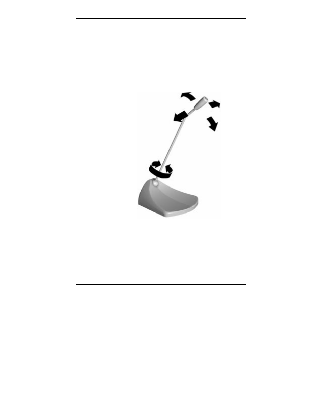
SPEAKERS
Multimedia models come with a pair of high-quality, 8-watt
stereo speakers that you can arrange to suit your work
environment.
An AC adapter comes with the system. To take full
advantage of your stereo speakers and system’s sound
capabilities, set up the speakers with the AC adapter. The
speakers connect to the line out jack on the back of the
system unit.
Power Lamp
Power Button
Treble
Bass
Volume Control
Headphone Jack
The right speaker features a power button, power lamp,
volume knob, treble and bass controls, and headphone jack.
Adjust the speaker volume by using the volume control or
by using the preinstalled sound system software. See
“Integrated Peripherals” in Chapter 4 for more information.
Use the sound software to balance the speakers.
1-12 Introducing Your Computer
8-watt speaker
The sound software is Voyetra Multimedia Sound Software.
See Chapter 6 for information on using the Multimedia
Sound Software.
MICROPHONE
The microphone allows you to record voice and sound into
your computer data files. See Chapter 6 for information on
recording sound using the Multimedia Sound Software.
Microphone
Introducing Your Computer 1-13

2
Getting Started
This chapter provides the information you need to start
using your system. Information includes:
Using a Mouse
If you are already familiar with using a mouse, skip this
section.
About Your Online Documentation
Read this section for an explanation of the online
document format and where to access it on your
computer.
Where to Go from Here
Look at this section for a quick reference to what you
can do and where you can get information.
USING A MOUSE
Use the mouse to quickly move around on the screen, to
select menu items, and to choose functions specific to your
software.
Use the mouse to
Click
Clicking selects an object on your screen. To “click,”
point to the object and press and release the left mouse
button.
Double click
Some actions require a double click to execute them. To
“double click” an object, point to the object and press
and release the left mouse button twice.
Getting Started 2-1
Press
Pressing the mouse button holds an action until you
release the mouse button.
Drag
Dragging the mouse attaches the pointer to an object on
the screen and allows you to highlight text or move an
object. To drag an object, point to the object, press the
left mouse button, and move the mouse to the new
location.
Typical screen objects that you click or double click are
icons, buttons, and menu options.
NOTE
If your mouse pointer disappears, m ove your
mouse in wide circles to bring it back into the
screen.
For more information about your mouse, see your online
User’s Guide and your application documentation. Also
included in the online documentation is information on
cleaning your mouse.
ABOUT YOUR ONLINE DOCUMENTATION
Besides this printed user’s guide, your system comes with
online documentation conveniently available right from the
Windows 95 desktop.
To access the online system documentation, locate NEC’s
PowerMate Online Documents group on the Windows 95
desktop. Double click NEC’s PowerMate Online
Documents icon. A welcome screen appears with the
information you need to use the online documentation.
2-2 Getting Started
The NEC PowerMate Ve ETC Series System
Documentation is a comprehensive source of information
about your system. To help you find the information you
need, the documentation is organized by topic and the
following modules:
System Tour
User’s Guide
Product Information Center
Option Installation Center
Support Center.
NOTE
Run the online NEC PowerMate Ve ETC
Series System Documentation at the shipping
default video resolution — 800 by 600 with 256
colors with small fonts.
Other online documents include:
Healthy Environment
Access the document by clicking Start on the Windows
95 desktop and pointing to Programs and NEC
Information Center.
Using Windows 95
Access the document by clicking Start on the Windows
95 desktop and pointing to Programs, Modern Age
Books, and Windows 95.
Most of your application programs provide extensive online
help at the touch of a button (usually the Help button).
Some programs provide separate online user’s guides for
specific applications. Windows 95 provides extensive online
help and “wizards” to guide you through procedures.
Getting Started 2-3

WHERE TO GO FROM HERE
Once you have your system up and running, we suggest that
you do the following:
If you have options to install, see Chapter 3, Installing
Options.
Make the distribution media, see “Operating System
Backup Utility” in Chapter 4.
Read Appendix A, Setting Up a Healthy Work
Environment.
Take the System Tour in your online NEC
PowerMate Ve ETC Series System Documentation.
See the online User’s Guide in your online NEC
PowerMate Ve ETC Series System Documentation.
Install any applications. See the documentation that
comes with the application.
2-4 Getting Started

See the following quick reference chart to find information
about some of the things you might want to do:
Quick Reference to Information About Your Computer
WHAT YOU WANT TO FIND WHERE TO FIND IT
Basic information about my
computer
Ask A.N.D.I.E.™ and
What On Earth
Online User’s Guide in
ETC Series System Documentation
Online
System Tour in NEC PowerMate Ve ETC
NEC PowerMate Ve
Series System Documentation
Printed
Ingenius Ask A.N.D.I.E and What On Earth
documentation
Microsoft® Office 97 Standard
Edition
Setting a password “Setting a Password” in the online User’s Guide
Online
Online help for each application
NEC PowerMate Ve ETC Series System
(
Documentation)
Chapter 4 in this guide
Using Windows Online
Using Windows 95
Printed
Windows 95 User’s Guide
The NEC PowerMate Customer catalog offers
additional Windows 95 and MS-DOS 6.2
documentation.
Loading a CD “Loading a CD” in the online User’s Guide
NEC PowerMate Ve ETC Series System
(
Documentation
)
Playing a music CD Multimedia models:
AudioStation online help
Chapter 6 in this guide
Using the suspend button “Saving Power” and “Managing Power” in the
online User’s Guide (
Series System Documentation
NEC PowerMate Ve ETC
)
Getting Started 2-5

Quick Reference to Information About Your Computer
WHAT YOU WANT TO FIND WHERE TO FIND IT
Adding options “Adding Internal Options” or “Adding External
Options,” in the online Option Installation
Center (
System Documentation)
Chapter 3 in this guide
NEC PowerMate Ve ETC Series
Understanding power
management
Changing video drivers “Changing Video Drivers” in the online User’s
“Saving Power” and Managing Power” in the
online User’s Guide (
Series System Documentation
NEC PowerMate Ve ETC Series System
Guide (
NEC PowerMate Ve ETC
)
Documentation)
Protecting my system from
viruses
Using Desktop Management
Interface
Using support services “24-Hour Information Services” in the online
Taking care of my system “Taking Care of Your System” in the online
“Scan95” and “WebScan” in the online System
NEC PowerMate Ve ETC Series System
Tour (
Documentation
“Desktop Management Interface” in the online
Product Information Center (
Ve ETC Series System Documentation
Support Guide (
Series System Documentation
Chapter 7 in this guide
User’s Guide (
System Documentation
)
NEC PowerMate
)
NEC PowerMate Ve ETC
)
NEC PowerMate Ve ETC Series
)
2-6 Getting Started

3
Installing Options
Your PowerMate system supports a variety of industrystandard and NEC expansion options. There are many
optional components available for you to customize your
computer.
monitors − your system supports the connection of a
VGA-compatible monitor such as NEC MultiSync XE
and XP series.
SIMM memory − your system comes with 16 MB of
Extended Data Out (EDO) RAM upgradeable to
128 MB of 32-bit, 60-ns high-speed memory using
SIMM sticks.
video DRAM − your system comes standard with 1 MB
of video DRAM that provides resolutions of up to 1280
by 1024 with 16 colors, 1024 by 768 with 256 colors,
800 by 600 with 256 colors, or 640 by 480 with 64,000
colors.
With the upgrade to 2 MB of DRAM, your system
supports resolutions up to 1280 by 1024 with 256 colors
or 640 by 480, 800 by 600, and 1024 by 768 with 16
million colors.
processor upgrade − a 320-pin zero insertion force (ZIF)
socket on the system board supports the primary
processor or an OverDrive processor for upgrades.
Installing Options 3-1

drives − your system supports a total of four storage
devices. In addition to the standard 3 1/2-inch 1.44 MB
diskette drive, three other storage device slots are
available. Hard disk configurations come with a hard
disk drive installed and multimedia systems include an
installed CD-ROM reader.
OPTION INSTALLATION PROCEDURES
Installation instructions for the following options are
provided in this chapter:
expansion boards
SIMM memory upgrade
video memory upgrade
processor upgrade
data storage devices
external options.
3-2 Installing Options

Some of the options require locating the connector on the
system board. See the following figure for connector
locations.
Cache Sock et
Pro cessor
Socket
SIMM
Socket 1
SIMM
Socket 2
SIMM
Socket 3
SIMM
Socket 4
Video DRAM
Socket
System board sockets and connectors
All options require the system cover removal. Procedures
for removing the cover are explained later in this chapter.
Installing Options 3-3

Safety Precautions
Take care when working inside the system and when
handling computer components. Avoid electric shock or
personal injury by observing the following warning.
Before remov ing the system unit cover, turn off the
power and unplug the system power cable. Power i s
removed only when the power cable is unplugged.
Static electricity and improper installation procedures can
damage computer components. Protect computer
components by following these safety instructions.
Electrostatic discharge can damage computer
components. Discharge stat ic el ectri cit y by touchi ng
a metal object before removing the system unit
cover.
!
WARNING
!
CAUTION
3-4 Installing Options
Avoid carpets in cool, dry areas. Leave an option, such
as a board or chip, in its anti-static packaging until
ready to install it.
Dissipate static electricity before handling any system
components (boards, chips, and so on) by touching a
grounded metal object, such as the system's unpainted
metal chassis.
If possible, use anti-static devices, such as wrist straps
and floor mats.

Always hold a chip or board by its edges. Avoid
touching the components on the chip or board.
Take care when connecting or disconnecting cables. A
damaged cable can cause a short in the electrical circuit.
Misaligned connector pins can cause damage to system
components at power-on.
When installing a cable, route the cable so it is not
pinched by other components and is out of the path of
the system unit cover. Prevent damage to the connectors
by aligning connector pins before you connect the cable.
When disconnecting a cable, always pull on the cable
connector or strain-relief loop, not on the cable.
Removing the System Unit Cover
The following procedure describes how to remove the
system unit cover.
!
Before remov ing the system unit cover, turn off the
power and unplug the system power cable. Power i s
removed only when the power cable is unplugged.
WARNING
1.
Turn off and unplug the system unit.
2.
Disconnect the keyboard, mouse, monitor, and any other
external options (such as a printer) from the rear of the
system unit.
Installing Options 3-5

!
Electrostatic discharge can damage computer
components. Discharge stat ic el ectri cit y by touchi ng
a metal object before removing the system unit
cover.
3.
Remove the two cover screws from the rear of the
CAUTION
system unit.
Screws
Removing cover screws
4.
3-6 Installing Options
From the rear of the system, grasp the sides and slide the
cover about an inch away from the front.
NOTE
The cov er fi t s tight l y. P ress the f ront edge of
the cover to release it from the front panel. Also
press against the rear panel to sli de the cover one
inch away from the front panel.

Lift the cover up and away from the system unit.
5.
Replacing the System Unit Cover
Replace the cover as follows.
Align the tabs on the sides of the cover with the inside
1.
unit frame as you position the cover over the chassis.
Releasing the cover
System Unit Frame
Cover Tabs
Replacing the system unit cover
Installing Options 3-7

Slide the cover forward to meet the front panel.
2.
NOTE
The cover fits tightly. If the cover does not
slide all t he way to the front panel , place one hand
on the front of the unit while you slide the cover
forward from the rear.
Secure the cover with the two cover screws removed
3.
earlier. (See “Removing the System Unit Cover,” earlier
in this chapter.)
Reconnect all external peripherals.
4.
Plug in your power cables.
5.
EXPANSION BOARDS
Your PowerMate supports ISA Plug and Play expansion
boards. With Plug and Play expansion boards, you can
install a board in an expansion slot without changing the
hardware settings. There are no system resource conflicts to
resolve. Plug and Play automatically configures the board
for the system.
Industry-standard 8- and 16-bit ISA, and 32-bit PCI
expansion boards are supported in the system unit. ISA
expansion boards can be Plug and Play or non-Plug and
Play boards.
Locating Expansion Slots
The PowerMate system has four expansion slots as follows.
two ISA slots (one slot occupied by the network board)
one PCI slot
one shared PCI/ISA slot.
3-8 Installing Options

ISA expansion slots support industry-standard 8-bit or 16bit expansion boards. The shared PCI/ISA slot also
supports a PCI expansion board. As noted in the following
figure, full size expansion boards cannot be installed in the
bottom slot and the inside slot. The bottom slot contains the
half-length network board (not shown in the figure). The
inside slot can be used for a three-quarter length board.
PCI expansion boards run at the system's processor speed.
The PCI bus handles 32 bits of data at a time, being wider
as well as faster than the standard ISA bus. PCI boards can
send and receive data much faster which boosts system
performance.
PCI Slot
PCI/ ISA Slot
ISA Slot*
* Full size expansion boards cannot be installed in these slots.
ISA Slot*
Locating expansion slots
Installing Options 3-9

Installing an Expansion Board
Install expansion boards in the system as follows.
Remove the system unit cover.
1.
Follow any preinstallation instructions that come with
2.
the expansion board (such as setting switches or jumpers
on the board).
If installing a board in the inside expansion slot (next to
3.
the power supply), see “Installing an Expansion Board
in the Inside Slot.” Otherwise, continue to the next step.
Remove the screw securing an expansion slot cover and
4.
remove the cover.
Save the screw for installing the expansion board. Save
the slot cover for future use.
3-10 Installing Options

!
A slot c over can damage the syst em board or any
option board i f it fall s into the system . Take car e to
keep the slot cover from f alling when rem oving the
screw.
If the slot cover does fall into the unit, remove it
before replacing the cover.
Slot Cover
CAUTION
Removing a slot cover
5.
Hold the board by its edges and insert it into the
expansion slot (see the figure on the following page).
Align full-size expansion boards with the guide rail at
the front of the system unit.
Press the board firmly into the expansion slot connector.
Gently rock the board from side-to-side to seat it into the
connector.
6.
Insert the screw removed earlier to secure the expansion
board to the support bracket.
Installing Options 3-11

Installing the expansion board
Attach any signal cables required by the expansion
7.
board.
Replace the system unit cover.
8.
Installing an Expansion Board in the Inside Slot
Use this procedure if installing an expansion board into the
inside slot in your system.
Remove the system unit cover.
1.
Follow any preinstallation instructions that comes with
2.
the expansion board (such as setting switches or jumpers
on the board).
Remove the two screws that secure the slot cover
3.
support and expansion slot cover to the rear of the
system.
Remove the slot cover support and slot cover from inside
the system unit.
3-12 Installing Options

!
Take car e not to drop the slot c over and support into
the system.
4.
Hold the board by its edges, component side down and
CAUTION
Slot Cover
Slot Cover Support
Screws
Removing the slot cover support screws
the bracket end facing the rear of the unit, and insert it
into the expansion slot.
Press the board firmly into the expansion slot connector.
Gently rock the board from side-to-side to seat it into the
connector.
Installing Options 3-13

Hold the slot cover support over the expansion board
5.
bracket and replace the two screws removed earlier. The
slot cover support secures the expansion board in place.
Expansion Board
Bracket
Attach any signal cables required by the expansion
6.
board.
Replace the system unit cover.
7.
Removing an Expansion Board
Remove the system unit cover as previously described.
1.
Screws
Slot Cover
Support
Attaching the slot cover support
2.
3-14 Installing Options
Label and remove any cables connected to the board.
NOTE
To remove a board from an inside slot, see
“Removing an Expansion Board from the Inside
Slot.”

Remove the screw that secures the board to the support
3.
bracket.
Removing the screw
Pull the board out of the connector. Gently rock the
4.
board from side-to-side to release it from its connector.
Replace the slot cover that was removed when the option
5.
board was installed.
Replace the system unit cover.
6.
Removing an Expansion Board from the Inside Slot
Use this procedure if removing an expansion board from the
inside slot in your system.
Remove the system unit cover.
1.
Label and remove any cables from the expansion board.
2.
Installing Options 3-15

Remove the two screws that secure the slot cover
3.
support and expansion board bracket to the rear of the
system.
Remove the slot cover support from inside the system
unit.
!
Take car e not t o drop the sl ot cover support i nt o t he
system, as it could damage the system board.
CAUTION
Expansion Board
Bracket
Screws
Slot Cover
Support
Removing the slot cover screw
4.
Pull the board out of the connector. Gently rock the
board from side-to-side to release it from the connector.
5.
Replace the slot cover that was removed when the option
board was installed.
6.
Replace the system unit cover.
3-16 Installing Options

SIMM UPGRADE
Your PowerMate system comes with 16 MB of main
system memory. Four sockets on the system board support
up to 128 MB of high-speed memory using industrystandard, tin-plated, single in-line memory modules
(SIMM).
parity SIMMs into the SIMM sockets.
Supported SIMMs include:
NOTE
You can install 60-ns EDO, parity or non-
1-MB by 32-bit (4-MB stick)
2-MB by 32-bit (8-MB stick)
4-MB by 32-bit (16-MB stick)
8-MB by 32-bit (32-MB stick).
!
To avoid corrosion between different metals, only
use tin-plated SIMM sticks.
CAUTION
Installing Options 3-17

Checking System Memory
Use the following procedure to:
check the memory installed in the system
determine the SIMM configuration needed to increase
memory
NOTE
SIMM memory must be installed in pairs of
the same memory type.
identify SIMM sockets.
Locate the four SIMM sockets on the system board (see
1.
“Option Installation Procedures” earlier in the chapter.
If any cables block access to the SIMM sockets, label
and disconnect them. If any boards block access to the
sockets, remove them.
2.
3-18 Installing Options
Use the following table to determine the SIMM
configuration needed to upgrade memory and to identify
the sockets for SIMM installation.

Recommended Memory Upgrade Path
TOTAL SIMM SIMM
MEMORY SOCKET 1 SOCKET 2 SOCKET 3 SOCKET 4
8 MB 4 MB 4 MB Empty Empty
16 MB 4 MB 4 MB 4 MB 4 MB
16 MB 8 MB 8 MB Empty Empty
24 MB 4 MB 4 MB 8 MB 8 MB
24 MB 8 MB 8 MB 4 MB 4 MB
32 MB 8 MB 8 MB 8 MB 8 MB
32 MB 16 MB 16 MB Empty Empty
40 MB 4 MB 4 MB 16 MB 16 MB
40 MB 16 MB 16 MB 4 MB 4 MB
48 MB 8 MB 8 MB 16 MB 16 MB
48 MB 16 MB 16 MB 8 MB 8 MB
64 MB 16 MB 16 MB 16 MB 16 MB
64 MB 32 MB 32 MB Empty Empty
72 MB 4 MB 4 MB 32 MB 32 MB
72 MB 32 MB 32 MB 4 MB 4 MB
80 MB 8 MB 8 MB 32 MB 32 MB
80 MB 32 MB 32 MB 8 MB 8 MB
96 MB 16 MB 16 MB 32 MB 32 MB
96 MB 32 MB 32 MB 16 MB 16 MB
128 MB 32 MB 32 MB 32 MB 32 MB
Installing Options 3-19

Removing a SIMM
Use the following procedure to remove a SIMM.
CAUTION:
system's metal chassis.
Remove the system unit cover.
1.
Locate the SIMM sockets (see “Option Installation
2.
Reduce static discharge by t ouchi ng the
Procedures” earlier in the chapter).
Press the metal clips at the outer edges of the socket
3.
away from the SIMM.
Push the SIMM away from the locking tabs and remove
4.
it from the socket.
Use the following procedure to install a SIMM stick.
3-20 Installing Options
Clips
Removing a SIMM

Installing a SIMM
Install a SIMM as follows.
Remove the system unit cover.
1.
Locate the SIMM sockets (see “Option Installation
2.
Procedures” earlier in the chapter).
Remove any currently installed SIMMs that are not
needed.
Bef ore instal l ing a S IMM , reduc e stati c di scharge by
touching the system's metal chassis.
3.
Align the notched end of the SIMM with the socket end
closest to the front of the system.
4.
Insert the SIMM at an angle into the socket.
!
CAUTION
Installing Options 3-21

Tilt the SIMM towards the locking tabs using equal
5.
pressure at the ends of the SIMM until it locks into the
socket.
Clip
Notched End of SIMM
Inserting the SIMM
Replace any cables or boards that may have been
6.
removed.
Replace the system unit cover.
7.
VIDEO UPGRADE
Upgrade the video memory to 2 MB by adding two 512-KB
by 16-bit video DRAM modules as follows.
Remove the system unit cover as previously described.
1.
Locate the video DRAM sockets (see “Option
2.
Installation Procedures” earlier in this chapter).
If any expansion boards are obstructing your view of the
sockets, remove the boards (see “Removing an
Expansion Board”).
3-22 Installing Options

!
Reduce static discharge by touching the system's
metal chassis.
3.
Align the notched ends of the module and socket. Using
CAUTION
equal pressure, gently press the module into the socket.
Repeat for the second module.
Notched End of
Module
Notched Corner
4.
Replace any boards that were removed.
5.
Replace the system unit cover.
of Socket
Aligning the video DRAM module with the socket
Installing Options 3-23

PROCESSOR UPGRADE
The zero-insertion force (ZIF) socket accepts pin-grid-array
(PGA) processors, such as the primary processor or an
OverDrive processor.
Incorrect installation of the processor can damage
the processor, system board, or both. Follow the
installation instructions carefully.
The system requires a heatsink on the OverDrive
processor. Verif y that you hav e the correct heatsink
for the processor.
When upgrading the processor, first remove the processor
currently installed in the system, then install the OverDrive
processor.
!
CAUTION
Removing the Processor
Remove the processor installed on the system board as
follows.
1.
Remove the system unit cover.
2.
Locate the processor socket (see “Option Installation
Procedures” earlier in this chapter).
If any expansion boards are obstructing the socket,
remove the boards.
3.
Release the heatsink clip from the tabs on the socket.
4.
Release the processor by pulling the lever on the socket
away from the socket and as far back as it goes without
forcing.
3-24 Installing Options

Before picking up the processor, reduce static
discharge by touching the metal frame of the
system unit. See “Safety Precautions” in this
chapter.
5.
Lift the processor out of the socket.
Installing the Processor
1.
Remove the processor currently in the system (see
previous procedure).
Before picking up the processor, reduce static
discharge by touching the metal frame of the
system unit.
!
CAUTION
!
CAUTION
2.
Align the notched corner of the processor with the
alignment corner in the socket and insert the processor.
3.
Swing the lever down to lock the processor into the
socket.
!
Remem ber to eit her reatt ach the heatsink used with
the old processor or install the new heatsink
supplied with the OverDrive processor.
CAUTION
Installing Options 3-25

Check to see if the newly installed processor requires a
4.
system board jumper change (see Chapter 5, Setting
System Board Jumpers).
Replace any boards removed during this procedure.
5.
Replace the system unit cover.
6.
DATA STORAGE DEVICES
The system board in the computer supports the following
storage devices:
up to two diskette drives, including the standard
1.44-MB diskette drive
up to four IDE devices such as IDE hard disks and an
IDE CD-ROM reader.
Other storage devices might require the installation of a
compatible controller board.
Locating Device Slots
Your system has four storage device slots (see the figure on
the following page):
3-26 Installing Options
a 3 1/2-inch accessible device slot which contains the
standard 1.44-MB diskette drive
one internal hard disk drive slot (1-inch high, thinheight) with an IDE hard disk installed
two accessible device slots (1.6-inch high, half-height)
In multimedia models, one accessible device slot
contains the standard CD-ROM reader.
Other accessible devices (diskette drive, tape drive,
CD-ROM reader) can be installed in the 5 1/4-inch slots.
A hard disk with a 5 1/4-inch form factor can be
installed in a 5 1/4-inch slot.

*
The following figure shows the device slot locations.
3 1/2-Inch
Internal Slot
*Top 5 1/4-inch slot is unavailable in s ome configurations.
Preparing the Device
Before installing a storage device in the system, follow any
preinstallation instructions that come with the device. For
example, check the following:
3 1/2-Inch Slot
(contains 1.44-MB
diskette drive)
5 1/4-Inch
Accessible Slots
Locating device slots
Diskette drive remove any termination on the optional
diskette drive. See the documentation that comes with
the drive.
IDE device check the jumper settings on the device
before installing it. See the documentation that comes
with the device for jumper setting information.
An IDE device, such as an IDE hard disk or IDE CDROM reader, must be set correctly as the first (master)
or second (slave) device on the IDE channel.
Installing Options 3-27

e
Device Cables
The cables used for installation of optional storage devices
include:
The diskette drive and IDE cables shipped with the system
each support two devices. Cable connector locations on the
system board are shown in the following figure.
The standard IDE hard disk is set as the master device
on the primary IDE connector. The CD-ROM reader in
multimedia models is the master device on the secondary
IDE connector.
diskette drive signal cable
IDE signal cables
system power cables.
3-28 Installing Options
Primary ID
Signal
Connector
Secondary
IDE Signal
Connector
Diskette Driv
Signal
Pin 1
Connector
System board cable connectors

Diskette Drive Signal Cable
A three-connector diskette drive signal cable comes attached
to the system board and to the standard 1.44-MB diskette
drive.
The installation of a second diskette drive in your system
does not require the replacement of the existing diskette
drive signal cable. Connect an optional diskette drive to the
middle connector on the standard diskette drive signal cable.
The colored edge of the cable goes to pin 1 on the cable
connector. Align the red edge of the cable with pin 1 (the
notched end) on the drive connector.
The following figure shows a three-connector diskette drive
signal cable.
Attaches to 1 .44-MB
Diskette Drive
Attaches to Optional
Diskette Drive
Attaches to
System Board
Optional diskette drive signal cable
Installing Options 3-29

IDE Signal Cables
Hard disk systems come with a three-connector IDE
interface cable attached to the primary IDE connector.
Multimedia systems come with a second IDE cable
connected to the CD-ROM reader and to the secondary IDE
connector.
Each IDE connector on the system board supports two IDE
devices. The addition of an IDE device to an IDE connector
does not require the replacement of the existing IDE signal
cable.
If installing an optional IDE CD-ROM reader, connect it to
the secondary IDE connector. The primary (fast) IDE port
should be reserved for hard disks.
The following figure shows a typical three-connector IDE
cable. If the IDE cable is not keyed with a connector tab,
align the colored edge of the cable with the pin 1 side of the
drive connector.
3-30 Installing Options
Connects to
System Board
IDE Port
Connects to
IDE Devices
Optional IDE cable connectors

System Power Cables
Power cables come from the power supply and are attached
to the standard storage devices. System power cables vary
in length and provide connector sizes to accommodate a
variety of supported storage configurations. Power cable
connectors are keyed to fit only in the correct position. The
following figure shows the power cable connectors.
Small Power
Cable Conne ctor
Large Power
Cable Conne ctor
Power cable connectors
Cabling Storage Devices
All storage devices require a power and signal cable
connection. Devices shipped with the system are already
connected.
Procedures are provided for the following optional devices:
IDE device − IDE hard disk drive or CD-ROM reader
diskette drive − 1.2-MB drive.
Installing Options 3-31

Cabling an IDE Device
Use the following procedure to cable an IDE device.
Connect the IDE signal cable connector to the connector
1.
on the IDE device.
Take care to prevent bending drive connector pins. Align
the IDE cable connector as shown in the following
figure.
Locate an available power connector coming from the
2.
power supply.
Connect the appropriate power cable to the power
3.
connector on the IDE device.
IDE
Cable
4.
3-32 Installing Options
Red
Edge
Power
Cable
Connecting IDE device cables
If you are installing an IDE CD-ROM reader, also
connect the audio cable (see the instructions that come
with the reader).

Cabling a Diskette Drive
Use the following procedure to cable a diskette drive.
Connect the diskette drive signal cable connector to the
1.
signal connector on the diskette drive as shown in the
following figure.
Locate an available power connector.
2.
Connect the power cable to the power connector on the
3.
device.
1.2-MB Diskette
Drive Connector
Red Edge
Power Cable
Diskette Drive
Signal Cable
Connecting 1.2-MB diskette drive cables
Installing Options 3-33

Installing Storage Devices
The following subsections describe how to install 3 1/2-inch
and 5 1/4-inch drives. The installation procedures include:
removing the 3 1/2-inch drive bracket
installing a 3 1/2-inch drive
removing the front panel
installing a 5 1/4-inch device
replacing the front panel
replacing the 3 1/2-inch drive bracket.
Removing the 3 1/2-Inch Drive Bracket
The 3 1/2-inch drive bracket containing the diskette drive
must be removed before installing a 3 1/2-inch or 5 1/4-inch
device.
Remove the 3 1/2-inch drive bracket containing the standard
1.44-MB diskette drive as follows.
1.
2.
3.
3-34 Installing Options
NOTE
Configurations that come with a hard disk
already instal led have a 3 1/2-inch hard disk driv e
located in the lower slot of the bracket.
Remove the system cover.
Remove the screw securing the drive bracket to the
chassis (see the following figure).
Slide the bracket to the rear of the chassis to release it
from the three bracket tabs.

Carefully lift the drive bracket up and place it on top of
4.
the power supply. Avoid pulling on the installed drive
cables.
Power
Supply
3 1/2-Inch
Drive
Bracket
Screw
Tab
Tabs
Removing the 3 1/2-inch drive bracket
Installing Options 3-35

3 1/2-Inch Drive Installation
Use the following procedure to install a hard disk drive into
the drive bracket.
Remove the system unit cover.
1.
Remove the 3 1/2-inch drive bracket from the system
2.
unit (see “Removing the 3 1/2-Inch Drive Bracket”).
Follow the preinstallation instructions that come with the
3.
device, such as setting jumpers and switches.
Insert the hard disk drive so that the connectors extend
4.
out of the bracket on the same end as the standard
diskette drive connectors.
Align the holes in the hard disk drive with the holes in
5.
the bracket.
Secure the device to the bracket with the four screws,
6.
two to a side, that come with the device.
3-36 Installing Options
Securing a 3 1/2-inch drive

Connect the drive cables.
7.
Replace the 3 1/2-inch drive bracket (see “Replacing the
8.
3 1/2-Inch Drive Bracket”).
Removing the Front Panel
Remove the front panel only if you are installing a 5 1/4inch device. The front panel does not need to be removed if
you are installing a 3 1/2-inch hard disk drive.
If you are installing a 3 1/2-inch hard disk drive, see
“Installing the 3 1/2-Inch Drive.”
Remove the system unit cover as previously described.
1.
Remove the front panel by releasing the four tabs from
2.
the back of the front panel.
Tabs
(behind front panel)
Identify the slot for the device being installed.
3.
Front Panel
Tabs
(behind front panel)
Blank Panel
Removing the front panel
Installing Options 3-37

Remove the blank panel from the selected slot by
4.
pressing the panel tabs from inside the front panel and
pushing the blank panel out.
Top Blank Panel Tabs
Remove the perforated metal plate from the selected slot
5.
on the chassis by pulling the metal plate back and forth
until it releases.
Install the device (see “Installing the 5 1/4-Inch
6.
Device”).
Installing the 5 1/4-Inch Device
Install an accessible device into the device cage as follows.
Remove the 3 1/2-inch drive bracket from the system
1.
unit (see “Removing the 3 1/2-Inch Drive Bracket”).
Remove the front panel (see “Removing the Front
2.
Panel”).
Follow the preinstallation instructions that come with the
3.
device, such as setting jumpers and switches.
Bottom Blank Pane l Tabs
Locating the blank panel tabs
3-38 Installing Options

NOTE
If the 5 1/4-inch device comes with drive
rails, do not attach them . Remov e any rai ls already
attached. See the documentation that comes with
the device.
From the front of the system, insert the device, connector
4.
end first, into the device slot.
NOTE
To easily access device connectors for
cabling, do not insert a 5 1/ 4-i nch devi ce al l t he way
into the slot.
Connect the device cables.
5.
Align the holes in the device with the holes in the cage.
6.
Secure the device to the cage with the four screws, two
7.
to a side, that come with the device. See the following
figure.
Installing Options 3-39

Securing the device
Replace the drive bracket (see “Replacing the 3 1/2-Inch
8.
Drive Bracket”).
3-40 Installing Options

Replacing the Front Panel
Replace the front panel only after it has been removed for a
5 1/4-inch device installation. If installing a 5 1/4-inch
device, see “Installing the 5 1/4-Inch Device.”
Align the four front panel tabs with the holes in the front
1.
of the system unit.
Evenly press the front panel into position until the tabs
2.
lock the panel in place.
Tabs
(behind front panel)
Continue to Step 5 in “Replacing the 3 1/2-Inch Drive
3.
Bracket.”
Front Panel
Tabs
(behind front panel)
Blank Panel
Aligning the front panel
Installing Options 3-41

Replacing the 3 1/2-Inch Drive Bracket
When replacing the 3 1/2-inch drive bracket, take care to
prevent pulling and loosening the cable connections.
Place the 3 1/2-inch drive bracket in the 3 1/2-inch
1.
device slot.
Slide the 3 1/2-inch drive bracket toward the front of the
2.
chassis so that the tabs secure the bracket.
Use the previously removed bracket screw to secure the
3.
bracket in place.
Screw
Power
Supply
3 1/2-Inch
Drive
Bracket
Tab
4.
5.
3-42 Installing Options
Tabs
Securing the 3 1/2-Inch drive bracket
Replace the front panel (see “Replacing the Front
Panel”).
Replace the system unit cover.

NOTE
If a 1.2-MB diskette drive was installed,
remove the protective cardboard insert from the
drive.
Run the Setup program to set the new configuration.
6.
ADDING EXTERNAL OPTIONS
This subsection includes installation procedures for the
following external options:
parallel printer
serial devices.
Connecting a Parallel Printer
Connect a parallel printer to the system as follows.
NOTE
Before connecti ng a pri nt er to t he system , be
sure the printer is set up correctly. Follow the setup
instructions that come with the printer.
Turn off power to the system and printer.
1.
Connect the printer cable to the printer port on the rear
2.
of the system unit (see the following figure).
Secure the cable with the screws provided.
3.
Connect the other end to the printer.
4.
If your printer requires ECP support, see “Integrated
5.
Peripherals Menu” in Chapter 4.
Installing Options 3-43

Connecting an RS-232C Device
Connect an RS-232C device to the system as follows.
Printer Port
Printer
Cable
Screws
Connecting a printer cable
1.
2.
3-44 Installing Options
NOTE
Before connecting a serial device to the
system, be sure the serial devi ce i s set up correc tl y.
Follow the setup instructions that come with the
option.
Turn off power to the system and to the serial device.
Connect one end of the serial cable to one of the two
serial ports on the rear of the computer.

Secure the cable with the screws provided.
3.
Connect the other end to the serial device.
4.
Seria l Port 2 Serial Port 1
Serial
Cable
Screws
Connecting an RS-232C cable
Installing Options 3-45

Setting System
4
Parameters
This chapter describes the Setup utility program that allows
you to enter system configuration information and control
special features of the system.
NOTE
Your system ships from the factory with the
correct system parameters for your configuration.
Unless you add optional har dware, you do not need
to run Setup to operate your system.
However, you might wish to run the Setup utility to
set features that customize your system, such as
security features.
System configuration information is stored in nonvolatile
memory. Nonvolatile memory retains its data when system
power is turned off. Nonvolatile memory in your system is a
complementary metal-oxide semiconductor (CMOS) chip.
A lithium battery supplies continuous power to CMOS
memory and maintains configuration information when
system power is off.
NOTE
NEC recomm ends that you print out or write
down your current Setup parameters and store the
information in a safe place. This lets you restore
your system to the current parameters if you ever
need to replace the battery.
Setting System Parameters 4-1

THE SETUP UTILITY
The Setup utility lets you view and set system parameters.
Use the Setup utility program to
set the time and date.
update or check system parameters when you add or
remove expansion options.
change or set power management features.
correct a hardware discrepancy when the Power-On
Self-Test (POST) displays an error message and
prompts you to run Setup.
check the installation of optional memory by comparing
the amount of memory installed with the amount of
memory displayed by Setup.
change certain system operating parameters, such as
boot device sequence and keyboard parameters.
configure system connections for peripherals such as
your diskette drive, hard disks, and devices connected to
the printer port and serial ports.
customize your system with security features such as
passwords, diskette drive restriction, virus check
reminder, and system backup reminder.
set system parameters in the event that your system
board was replaced.
4-2 Setting System Parameters

HOW TO START SETUP
To start the Setup utility, follow these steps:
Turn on or reboot your system. Setup displays the
1.
following message:
Press <F2> to enter SETUP
Press F2. Setup’s Main Menu window appears similar
2.
to the following screen.
NOTE
The screen shown is typical of your system.
The actual items on the Main Menu depend upon
the hardware installed in your system.
PhoenixBIOS Setup — Copyright 1992-96 Phoenix Technologies Ltd.
Main Advanced Security Power Boot Exit
System Time [10 :19:20] Item Specific Help
System Date [03/14/1997]
Diskette A [1.44 MB, 3 ½"] <Tab>, <Shift-Tab>, or
Diskette B [Not Installed] <Enter> selects field.
> IDE Adapter 0 Master C: 1280 Mb
> IDE Adapter 0 Slave None
> IDE Adapter 1 Master CD-ROM
> IDE Adapter 1 Slave None
Video System [EGA/VGA]
> Memory Cache
> Memory Shadow [Enabled]
> Boot Options
> Numlock [Auto]
System Memory 640 KB
Extended Memory 15 MB
F1 Help
ESC Exit
Select Item -/+ Change Values F9 Setup Defaults
↑↓
Select Menu Enter Select > Sub-Menu F10 Previous Values
←→
Main Menu
Setting System Parameters 4-3

HOW TO USE SETUP
The Setup utility has a Main Menu window and five toplevel menus with submenus.
The Main Menu window contains the following areas:
A title line — the top line of the Main Menu. This line
displays the Setup utility name and copyright message.
The menu bar — the line under the Setup title line. The
menu bar contains five top-level menus that you can
choose to set system parameters.
A Main Menu summary window — the center area on
the left side of the screen. This area provides a summary
of Main Menu Setup parameters. You can set some
Main Menu parameters directly from this window or
you can set them from the Main menu option in the
legend bar.
The Field Help window or Item Specific Help — the
area on the right side of the screen. This help area
provides help information for the Setup option currently
selected.
The legend bar — the area at the bottom of the screen.
The legend bar provides a summary of command keys
for using Setup.
The General Help window — a window that appears
any time during Setup when you press
help window provides two pages of general information
about using Setup.
The following sections describe how to use the Main Menu
window to set system parameters.
4-4 Setting System Parameters
F1
or
Alt H
. This

The Menu Bar
The menu bar at the top of the Main Menu window lists
these menus:
Main — Use this menu for basic system configuration.
For example, select “Main” to set the system time,
system date, diskette drives, and video parameters.
Use this menu to check memory parameters.
Advanced — Use this menu to set serial port and printer
port addresses and interrupts, and to enable/disable the
system’s diskette drive controller and dual-IDE
controllers.
The Advanced menu also provides menu items for
setting parity and for setting parameters for large disks
(for example, to use large disks with Windows NT™).
Some of the Advanced features are accessible only with
a Supervisor password when the Supervisor password is
set.
Security — Use this menu to set User and Supervisor
Passwords and the Backup and Virus-check reminders.
Power — Use this menu to configure Power
Management features.
Exit — Use this menu to exit the current menu.
To select an option from the menu bar, use the left and right
← → arrow keys.
See “Exiting Setup” in this chapter for a description on
exiting the Main Menu.
Setting System Parameters 4-5

The Legend Bar
Use the keys listed in the legend bar on the bottom of the
Setup menu to make your selections or exit the current
menu. The following table describes the legend keys and
their alternates.
Setup Key Functions
KEY FUNCTION
F1 or Alt-H Displays the General Help window (described later
in this chapter).
Esc Exits the menu.
← or → arrow keys
↑ or ↓ arrow keys
Tab or Shift-Tab Cycles the cursor up and down for item selection.
Home or End Moves the cursor to the top or bottom of the
Page Up or Page Down Moves the cursor to the next or previous page.
F5 or - Selects the Previous Value for the field.
F6 or + or Space Selects the Next Value for the field.
F9 Loads the Default Configuration values for this
F10 Loads the Previous Configuration values for this
Enter Executes a command or selects a submenu.
Alt-R Refreshes the screen.
Selects a different menu.
Moves the cursor up and down for item selection.
window.
menu.
menu.
4-6 Setting System Parameters

Selecting a Menu Item
To select a menu item, use the arrow keys to move the
cursor to the field you want. Then use the value keys (F5, -,
F6, +, or space bar) to cycle through the value for that field.
The Save Values command in the Exit Menu saves the
values currently displayed in all the menus.
Displaying a Submenu
To display a submenu, use the arrow keys to move the
cursor to the submenu you want. Then press
pointer (a right-pointing triangle) marks all selectable
submenus.
Getting Help
A Field Help window or Item Specific Help window on the
right side of each menu displays the help text for the
currently selected Setup option. It updates as you move the
cursor to each new field.
Enter
. A
Pressing
F1
Help window that describes the legend keys and their
alternates.
The scroll bar on the right of any window indicates that
there is more than one page of information in the window.
Use
Page Up
Pressing
Press
Home
to exit the current window.
Esc
MAIN MENU OPTIONS
The following table lists and describes the available
parameters when you select the Main menu in the legend
bar. Other Main Menu parameters are available by
selecting submenus.
or
Alt H
and
and
on any menu brings up the General
Page Down
End
to display all the pages.
displays the first and last page.
Setting System Parameters 4-7

Parameters available directly from the Main Menu
summary window have a right-pointing triangle next to the
parameter. Use the arrow keys to move the cursor to the
parameter and press
to select a submenu.
Enter
See the sections following the table for a description of
Main Menu parameters from the summary window.
Main Menu Parameters
PARAMETER OPTIONS DESCRIPTION
System Time HH:MM:SS Sets the system time.
System Date MM/DD/YYYY Sets the system date.
Diskette A:
Diskette B:
IDE Adapter Auto (default) Described in the following
Video System Monochrome
Memory Cache Described in the following
360KB, 5 1/4”
1.2MB, 5 1/4”
720KB, 3 1/2”
1.44MB, 3 1/2” (default A)
2.88MB, 3 1/2”
Not Installed (default B)
EGA/VGA (default)
CGA 80x25
Selects the type of diskette
drive in your system.
sections.
Selects the default video
device.
sections.
Memory Shadow Enabled (default) Described in the following
sections.
Boot Options Described in the following
sections.
NumLock Auto (default) Described in the following
sections.
System Memory Automatically detected
by the system
Extended Memory Automatically detected
by the system
4-8 Setting System Parameters
Displays the amount of
conventional memory
detected at power-on.
Displays the amount of
extended memory detected
at power-on.

IDE Adapters
IDE adapters control the IDE devices, such as IDE hard
disk drives and IDE CD-ROM readers, in your system.
Your system uses two IDE controllers integrated on the
system board.
Setup supports up to four IDE devices, with an IDE adapter
for each of the following configurations:
1 Master
1 Master, 1 Slave
2 Masters
2 Masters, 1 Slave
2 Masters, 2 Slaves
The master/slave combination for a standard hard disk
configuration is “1 Master.” If you add a hard disk to the
fast IDE port (IDE1 connector), the combination becomes
“1 Master, 1 Slave.” Change the jumper setting on the IDE
device to set the device to master or slave (see the
documentation that comes with the device).
For multimedia systems, the IDE hard disk and CD-ROM
reader are both “Masters.” The hard disk drive is the
“Master” on the primary connector and the CD-ROM
reader is the “Master” on the secondary connector. If you
add an IDE hard disk to the system, the combination
becomes “2 Masters, 1 Slave.”
NOTE
If you c hange the CD-ROM reader setti ng in
the multimedia configuration, the CONFIG.SYS and
AUTOEXEC.BAT require changes as well.
Setting System Parameters 4-9

Select the IDE Adapter option configuration directly from
the Main Menu summary window. Available options
include:
IDE Adapter 0 Master
IDE Adapter 0 Slave
IDE Adapter 1 Master
IDE Adapter 1 Slave.
IDE Adapter 0 configures the fast IDE port (IDE1
connector), and IDE Adapter 1 configures the standard IDE
port (IDE2 connector).
Each IDE Adapter parameter has a right-pointing arrow to
the left of it. Selecting the option displays IDE hard disk
parameters. Select an IDE Adapter option and set
parameters for each hard disk separately.
Use the following table to configure the hard disk. If your
IDE hard disk features auto IDE type detection, you need
only to select the Autotype Fixed Disk parameter. The
system then automatically detects the hard disk type and
sets the remaining parameters.
NOTE
I f your IDE har d disk f eat ures auto I DE type
detection, you need only to select the Autotype
Fixed Disk parameter. The system then
automatically detects the hard disk type and sets
the remaining parameters.
4-10 Setting System Parameters

IDE Hard Disk Parameters
PARAMETER OPTIONS DESCRIPTION
Type 1 to 39
User
Auto
Cylinders 1 to 16,384 Specifies the number of cylinders.
Heads 1 to 16 Specifies the number of read/write
Sectors/Track 1 to 63 Specifies the number of sectors per
Write Precomp 0 to 65534
None
Multi-Sector
Transfers
LBA Mode Control Enabled
32 Bit I/O Enabled (default)
Transfer Mode Standard
2, 4, 8, 16, Sectors
Disabled
Disabled (default)
Disabled
Fast PIO1, PIO2,
PIO3, PIO4
Selecting 1 to 39 fills in all remaining
fields with values for predefined disk
type. “User” prompts the user to fill in
remaining fields. When “Auto” is
selected the BIOS automatically sets
the drive type.
heads.
track.
Specifies the number of the cylinder at
which to change the write timing.
Specifies the number of sectors in
multi-sector transfers.
Sets LBA Mode Control on or off.
Sets 32 bit I/O to on or off.
Specifies the transfer mode.
Memory Cache
For memory caching parameters, select Memory Cache
directly from the Main Menu summary window. See the
following table for a description of memory cache
parameters.
Setting System Parameters 4-11

!
Incorrect settings can cause the system to
malfunction.
Memory Cache Parameters
PARAMETER OPTIONS DESCRIPTION
CAUTION
External Cache Enabled (default)
Disabled
Cache Video BIOS
area
Caching Memory
Regions
Enabled (default)
Disabled
Enabled
Disabled (default)
Memory Shadow
Memory Shadow is set to enable as the default. Various
options set to disable can also be enabled.
Boot Options
Your system might require a Supervisor password to set
Boot parameters. Select “Boot Options” directly from the
Main Menu summary window to display the “Boot
Options” menu.
Sets the state of external cache.
Controls caching of the video BIOS
area.
Default is disabled. Cache shadows
optional memory. ROM located in
specified segments of memory and
can improve performance.
Some add-in cards, particularly with
on-board firmware, do not work
properly when shadowed.
CAUTION
:
Use the legend keys to make your selections and exit to the
Main Menu. Use the following table to select your boot
options.
4-12 Setting System Parameters

Boot Option Parameters
PARAMETERS OPTIONS DESCRIPTION
Summary Screen Enabled (default)
Disable
Floppy Check Enabled (default)
Disabled
Last Boot Fail 3 (default)
User-selectable settings
Disabled
NumLock
Select “NumLock” directly from the Main Menu summary
window to display the Keyboard Features menu.
Use the legend keys to make your selections and exit to the
Main Menu. Use the following table to configure the
keyboard parameters.
Displays system configuration at the
end of boot-up.
Verifies diskette type during bootup.
Disabling speeds boot time.
Sets the number of times you can
attempt to boot the system. If the
system fails to boot on the set
number of tries, the “Previous Boot
Incomplete” message appears and
the system boots with default
settings.
The default setting, 3, gives you
three tries to boot the system before
the “Previous Boot Incomplete”
message appears.
Setting System Parameters 4-13

Keyboard Features Parameters
PARAMETERS OPTIONS DESCRIPTION
Numlock Auto (default)
On
Off
Keyboard AutoRepeat Rate
Keyboard AutoRepeat Delay
Key Click Enabled
Fast (default)
Medium
Slow
1/4 sec
1/2 sec (default)
3/4 sec
1 sec
Disabled (default)
THE ADVANCED MENU
Accessing the Advanced menu might require a Supervisor
password. When you select the Advanced menu, you also
can access the Integrated Peripherals menu.
The following table explains the Advanced menu
parameters.
On or Off turns Num Lock on or off
at bootup. Auto turns Num Lock on
if it finds a numeric key pad.
Sets the delay time after the key is
held down and before it begins to
repeat the keystroke.
Turns audible key click on or off.
Setting menu items in the Advanced menu to
incorrect values can cause your system to
malfunction.
4-14 Setting System Parameters
!
CAUTION

g
)
y
g
y
y
)
)
y
y
g
y
Advanced Menu Parameters
PARAMETER OPTIONS DESCRIPTION
Plug & Play OS No
Yes (default)
Reset Configuration
Data
ISA graphics
device installed
Big Memory Mode Normal (default
Select “Normal” for MS-DOS and
Select “Alternate” for OS/2® and
Large Disk Access
Mode
No (default
Yes
No (default) Yes Set to “Yes” if other system devices
Alternate
DOS (default
Other
Select “Yes” if you are using a Plu
& Play capable operating system
such as Windows 95. Otherwise,
set to “No.”
If Windows 95 or the ICU has
difficulty configuring the system, tr
setting this parameter to “Yes” to
clear all of the confi
This parameter resets automaticall
to “No” to reboot.
need to know
graphics device installed.
Selects the method the BIOS uses
to report memory sizes over 64 MB
to the operating system.
Windows.
Windows NT™.
Select DOS if
Other if
system such as Novell Netware or
UNIX.
ou have another operatin
uration data.
ou have an ISA
ou have DOS. Select
A large disk is one that has more
than 1024 c
heads, or more than 63 tracks per
sector.
linders, more than 16
Integrated Peripherals Menu
Select the “Integrated Peripherals” menu on the Advanced
Menu to configure the connections between the system
processor and the I/O ports (serial port 1, serial port 2, and
the printer port), the diskette drives, and hard disk
controllers.
Setting System Parameters 4-15

NOTE
A Supervisor password might be required to
select parameters from the Integrated Peripherals
menu.
Use the legend keys to make your selections and exit to the
Main Menu. Use the table that follows to configure your
peripherals.
Integrated Peripherals Parameters
FEATURE OPTIONS DESCRIPTION
COM A Port
COM B Port
LPT Port Disabled
LPT Mode Output only (default)
ECP Channel DMA 0
Disabled
User-selectable settings
Auto
378, IRQ 7 (default)
User-selectable settings
Auto
Remove
Remove
DMA 1
DMA 3
Selects a unique address and
interrupt request for the listed COM
ports. Auto selects the next available
combination.
Factory settings:
COM A default: 3F8, IRQ4
COM B default: 2F8, IRQ3
Selects a unique address and
interrupt request for the LPT port.
Auto selects the next available
combination.
Enables parallel port to function
normally (Output only),
bidirectionally, or in an enhanced
capabilities port (ECP) mode. Check
your printer documentation to set the
correct LPT mode for your printer.
Available when ECP is selected for
the LPT mode.
4-16 Setting System Parameters

Integrated Peripherals Parameters
FEATURE OPTIONS DESCRIPTION
Diskette
Controller
Local Bus IDE
Adapter
PS/2 Mouse Enabled (default)
On-board
Sound
Enabled (default)
Disabled
Both (default)
Disabled
Primary
Disabled
Stereo with SRS (default)
Stereo
Disabled
THE SECURITY MENU
Selecting “Security” from the Main Menu displays a menu
with system security options.
Enables the on-board diskette drive
controller.
Enables the on-board IDE controllers.
“Both” enables the primary (fast)
channel and secondary (standard)
channel. “Primary” enables only the
primary (fast) channel.
Enables/disables PS/2-style mouse.
This parameter is only available
when the BIOS detects integrated
audio on the system board. When
the audio is detected, stereo with
surround sound is the default.
If playing an audio file with SRS
built-in, use the Stereo setting.
Choose Mono when stereo sound is
not desired.
NOTE
You can enter the Setup program wi th either
a User or Supervisor password. However, more
Setup choices are available with a Supervisor
password.
The User Password can only be set after setti ng a
Supervisor Password.
Setting System Parameters 4-17

!
The features that you set in the Security menu
affect the features that appear on the Security menu
as well as on other Setup menus.
CAUTION
Enabling “Supervisor Password” requires a password for
entering Setup. Passwords are not case sensitive.
Enter
Pressing
at either Set Supervisor Password or Set
User Password on the menu displays a Set Password dialog
box with the following prompts:
Enter new password: [ ]
Re-enter new password: [ ]
To set a password, type the password and press
Reenter your password and press
NOTE
If you forget your password, see “Clearing
Your Password” in Chapter 5.
Enter
.
Enter
.
See the following table for a description of the security
features you can select. Use the legend keys to make your
selections and exit to the Main Menu.
4-18 Setting System Parameters

System Security Options
FEATURE OPTIONS DESCRIPTION
Supervisor Password Disabled (default)
Enabled
Set Supervisor
Password
Up to seven
alphanumeric
characters
User Password Disabled (default)
Enabled
Set User Password Up to seven
alphanumeric
characters
Password on Boot Disabled (default)
Enabled
Sets to Enabled when entering a
password at Set Supervisor
Password.
Pressing
Enter
displays a dialog
box for entering the supervisor
password. This password gives
FULL access to Setup menus.
Must set to Enabled to set a User
password.
Pressing
Enter
displays the dialog
box for entering the user password.
This password gives RESTRICTED
access to Setup menus. Requires
the prior setting of a Supervisor
password.
Enabled requires a password on
boot (cold boot only — no
password required for warm boot).
Requires the prior setting of a
Supervisor and/or User password.
If disabled, password(s) are
required for entering Setup but are
not required for booting.
If a Supervisor password is set
and this option is disabled, the
BIOS boots without asking for a
password.
Diskette Access User (default)
Supervisor
Fixed Disk Boot
Sector
Normal (default)
Write Protected
Supervisor setting restricts
the use of diskette drives to a
supervisor. Requires setting the
Supervisor password.
Write protected helps prevent
viruses. When write protected,
operating systems (and viruses
and application programs) which
attempt to modify the boot sector
will not be able to do so.
Setting System Parameters 4-19

System Security Options
FEATURE OPTIONS DESCRIPTION
System Backup
Reminder
Virus Check
Reminder
THE POWER MENU
Selecting “Power” from the menu bar displays a screen
with the power management parameters described in the
following table.
A power management system reduces the amount of energy
used after specified periods of inactivity. The Power menu
supports a Full-On state, a Standby state with partial power
reduction, and a Suspend state with full power reduction.
See “Power Management” in the online User’s Guide for
additional information about managing power.
Disabled (default)
Daily
Weekly
Monthly
When a schedule is specified,
displays a message during bootup
asking (Y/N) if you have backed
up the system or scanned it for
viruses.
Message returns on each boot
until you respond with “Y”.
Daily displays the message on
the first boot of the day, weekly
on the first boot after Sunday,
and monthly on the first boot of
the month.
Use the Power menu to specify your settings for Power
Management. Use the following table to make your
selections.
4-20 Setting System Parameters

NOTE
To disable all power management features,
set advanced power management (APM) to
Disabled. See the following table to set power
management parameters.
Power Management Parameters
FEATURE OPTIONS DESCRIPTION
APM Enabled (default)
Disabled
Keyboard
Wakeup
Mouse Wakeup Enabled (default)
Power
Management
Mode
IRQs to Monitor Enabled (default)
Sleep Timeout 15 min (default)
Deep Sleep
Timeout
Video in Sleep
Mode
Enabled (default)
Disabled
Disabled
Customize (default)
Disabled
Maximum
Medium
Minimum
Disabled
Disabled
User selectable
15 min (default)
Disabled
Off (default)
On
Advanced power management (APM)
allows APM-aware software to better
manage power savings.
Allows keyboard activity to wake up
system.
Allows mouse activity to wake up
system.
Maximum, Medium, and Minimum
set power-management options with
predefined values. Select Customize
to select your own level of power
management.
Controls if activity on IRQs 3, 4, 5, 7,
9, 10, and 11 keeps the system awake
or wakes the system from a deep
sleep. The IRQs are shipped enabled.
Inactivity period required before partial
power shutdown (Standby User
selectable mode).
Inactivity period required after Sleep
timeout to maximum power. User
selectable shutdown (Suspend mode).
Off turns monitor off in Sleep mode.
Setting System Parameters 4-21

THE BOOT MENU
Selecting “Boot” from the menu bar displays the following
list of boot devices:
Diskette Drive
CD-ROM reader
Hard Drive
THE EXIT MENU
Selecting “Exit” from the menu bar displays the following
exit options. Note that
must select one of the items from the menu or menu bar to
exit.
Save Changes & Exit
Discard Changes & Exit
Get Default Values
Load Previous Values
Save Changes.
does not exit this menu. You
Esc
Save Changes & Exit
After making your selections on the Setup menus, always
select Save Changes to Non-Volatile RAM (NVRAM) to
make them operative.
Unlike standard RAM memory, NVRAM is sustained by a
real-time clock chip and stays on after you turn your system
off.
After you save your selections, the program displays this
message:
Values have been saved to CMOS!
Continue
If you attempt to exit without saving, the program asks if
you want to save before exiting.
4-22 Setting System Parameters

During bootup, Setup attempts to load the values you
saved in NVRAM. If the values saved in NVRAM cause
the system boot to fail, reboot and press
In Setup, you can load the ROM default values (as
described in “Get Default Values”) or try to change the
values that caused the boot to fail.
Discard Changes & Exit
Use this option to exit Setup without recording any changes
you may have made.
Get Default Values
To load all the default Setup values in the Setup menus,
press
message:
If, during bootup, the BIOS program detects a problem in
the integrity of values stored in NVRAM, it displays these
messages:
(setup defaults). The program displays this
F9
Default values have been loaded!
[continue]
to enter Setup.
F2
System CMOS checksum bad - run SETUP
Press <F1> to resume, <F2> to Setup
The CMOS values have been corrupted or modified
incorrectly, perhaps by an application program that changes
data stored in CMOS.
Press
to resume the boot or F2 to run Setup with the
F1
ROM default values already loaded into the menus. You
can make other changes before saving the values to
NVRAM.
Setting System Parameters 4-23

Load Previous Values
If, during a Setup session, you change your mind about
your selections and have not yet saved the values to
NVRAM, you can restore the values you previously saved
to NVRAM.
Selecting Load Previous Values on the Exit menu updates
all the selections and displays this message:
Previous values have been loaded!
[continue]
Save Changes
Save Changes saves all the selections without exiting Setup.
You can return to the other menus if you want to review and
change your selections.
RESTORING SYSTEM SOFTWARE
The Product Recovery CD that comes with your system
contains everything you need to:
restore individual files on your system
completely recover your system.
You also need a CD-ROM drive (standard with multimedia
systems) to run the Product Recovery CD.
The Product Recovery CD lets you copy individual
program files from the Product Recovery CD if any of your
factory-installed software files become corrupted. You can
also restore all your system software files to their original
factory-installed state if your preinstalled software becomes
unusable.
The following information describes the available
restoration options and how to restore your system software
if it becomes necessary.
4-24 Setting System Parameters

System Restore Options
System restore options available to you are as follows:
Restore Individual Files
This option lets you select the files and directories you
want restored from the Product Recovery CD. Use this
option to restore only a few files or to have total control
of which files and directories are restored to their factory
state. This option is also useful for restoring
AUTOEXEC, CONFIG, and INI files.
This procedure is done in Windows 95. The restore
individual files procedure requires booting the system
form the hard disk, entering Windows, and inserting the
CD into the CD-ROM reader.
System Recovery
Use this option as a last resort when your preinstalled
software becomes unusable and you cannot reboot
from the hard disk. This option requires booting from
the Recovery CD.
The System Recovery option provides a full system
recovery. This option lets you restore your system to its
original factory-shipped state. Full System Recovery
reformats hard drive C and erases all information on
the disk. It then restores files on drive C from the System
Recovery CD.
The following sections describe each of these options. If
your preinstalled software becomes unusable, see
“Recovery Options” later in this chapter.
Setting System Parameters 4-25
 Loading...