

Nec POWERMATE PRO2200, POWERMATE PRO2180 user Manual

PROPRIETARY NOTICE AND LIABILITY DISCLAIMER
The information disclosed in this document, including all designs and related materials, is
the valuable property of NEC Computer Systems Division, Packard Bell NEC, Inc.
(hereinafter “NECCSD”) and/or its licensors. NECCSD and/or its licensors, as appropriate,
reserve all patent, copyright and other proprietary rights to this document, including all design, manufacturing,reproduction, use, and sales rights thereto, except to the extent said
rights are expressly granted to others.
The NECCSD product(s) discussed in this document are warranted in accordance with the
terms of the Warranty Statement accompanying each product. However, actual
performance of each such product is dependent upon factors such as system configuration,
customer data, and operator control. Since implementation by customers of each product
may vary, the suitability of specific product configurations and applications must be
determined by the customer and is not warranted by NECCSD.
To allow for design and specification improvements, the information in this document is
subject to change at any time, without notice. Reproduction of this document or portions
thereof without prior written approval of NECCSD is prohibited.
FaxFlash is a trademark of NEC Computer Systems Division (NECCSD), Packard Bell NEC, Inc.
NEC is a registered trademark of NEC Corporation; MultiSync and PowerMate are registered trademarks of NEC Technologies, Inc.; these
registered trademarks are used under license by NEC Computer Systems Divison (NECCSD), Packard Bell NEC, Inc.
All other product, brand, or trade names used in this publication are the trademarks or registered trademarks of their respective trademark
owners.
First Printing — August 1997
Copyright 1997
NEC Computer Systems Division
Packard Bell NEC, Inc.
1414 Massachusetts Avenue
Boxborough, MA 01719-2298
All Rights Reserved

Contents
Preface.........................................................................................................................vii
Section 1 Technical Information
System Chassis ............................................................................................................1-2
System Board ..............................................................................................................1-3
Processor and Secondary Cache............................................................................1-5
System BIOS........................................................................................................1-6
I/O Addressing......................................................................................................1-7
System Memory....................................................................................................1-9
Interrupt Controller...............................................................................................1-10
Plug and Play........................................................................................................1-11
ISA Bus................................................................................................................1-11
PCI Local Bus ......................................................................................................1-11
iii
PCI/IDE Ports ......................................................................................................1-11
Parallel Interface...................................................................................................1-12
Serial Interface......................................................................................................1-12
USB Interface.......................................................................................................1-13
Infrared Interface..................................................................................................1-14
Video Board................................................................................................................1-14
Video Support ......................................................................................................1-14
Video Playback.....................................................................................................1-15
Audio ..........................................................................................................................1-16
SCSI Board .................................................................................................................1-17
Diskette Drive..............................................................................................................1-18
Hard Disk Drive...........................................................................................................1-18
IDE Hard Drives...................................................................................................1-18
SCSI Hard Disk....................................................................................................1-19
Eight-Speed CD-ROM.................................................................................................1-19
CD-ROM Reader Operation..................................................................................1-19
CD-ROM Reader Settings.....................................................................................1-20
Power Supply ..............................................................................................................1-21
Keyboard.....................................................................................................................1-21
Mouse .........................................................................................................................1-21
Speakers......................................................................................................................1-21
Microphone .................................................................................................................1-21

iv Contents
LANDesk Client Mananger..........................................................................................1-21
PC Health Indicator .............................................................................................. 1-22
Managing Workstations ................................................................................. 1-22
PC Health Meter............................................................................................1-22
PC Health Description....................................................................................1-22
Inventory .......................................................................................................1-23
Using DMI.....................................................................................................1-24
Heceta Capabilities................................................................................................1-24
Specifications...............................................................................................................1-25
Section 2 Installing Software
Monitor Selection on First Boot...................................................................................2-1
LANdesk Client Manager Setup...................................................................................2-1
Crystal Audio Drivers/Business Audio Mixer and MIDI Installation.............................2-2
Installing Crystal Audio Drivers ............................................................................2-2
Setting Up MIDI Support .....................................................................................2-2
McAfee’s Virus Scan For Windows NT.......................................................................2-2
Enabling the Adaptec SCSI Board (SCSI Models Only)...............................................2-3
Release Notes..............................................................................................................2-4
Infrared (IR) Interface...........................................................................................2-4
Unsupported Monitor Resolutions.........................................................................2-4
Interrupt Assignment.............................................................................................2-4
Secondary Drive Configuration.............................................................................2-4
AVI Distortion......................................................................................................2-5
Using 16-Bit Applications.....................................................................................2-5
Advanced Power Management..............................................................................2-5
Suspend “Sleep” Button.................................................................................2-5
Using LANDesk Client Manager...........................................................................2-5
Accessing the LANDesk Client Online Guide.................................................2-5
“Discover” Feature.........................................................................................2-6
Heavy Network Use with Other PowerMate Models......................................2-6
Multiple Admin Sessions................................................................................2-6
Audio Not Listed in DMI...............................................................................2-6

Contents v
Section 3 Troubleshooting
Problems and Solutions................................................................................................3-1
NECCSD Service and Information...............................................................................3-6
Online Services.....................................................................................................3-7
NECCSD FaxFlash Service............................................................................3-7
NECCSD Bulletin Board Service ...................................................................3-8
E-Mail/Fax Technical Support Service ........................................................... 3-10
Internet..........................................................................................................3-10
NECCSD Technical Support Services............................................................3-11
Section 4 Illustrated Parts Breakdown
List of Figures
1-1 System Controls and Storage Device Slots.....................................................1-2
1-2 Rear Panel Features........................................................................................1-3
1-3 IDE Hard Disk Drive Jumper Settings............................................................1-18
1-4 CD-ROM Reader Controls and Indicators......................................................1-20
1-5 CD-ROM Jumper Settings .............................................................................1-20
4-1 PowerMate Pro2200/2180 Series Illustrated Parts Breakdown.......................4-4
List of Tables
1-1 System Board Feature Components................................................................ 1-5
1-2 System Memory Map.....................................................................................1-7
1-3 I/O Address Map ...........................................................................................1-7
1-4 IRQ Assignments ...........................................................................................1-10
1-5 Parallel Port Addressing and Interrupts ..........................................................1-12
1-6 Serial Port Addressing and Interrupts.............................................................1-13
1-7 Specifications.................................................................................................1-25
3-1 Problems and Solutions..................................................................................3-1
3-2 NECCSD Service and Information Telephone Numbers .................................3-6
4-1 PowerMate Pro2200/2180 Series Field-Replaceable Parts List ....................... 4-1
4-2 PowerMate Pro2200/2180 Series Options......................................................4-5
4-3 PowerMate Pro2200/2180 Series Documentation and Packaging ...................4-5

vi Contents

Preface
This addendum to the PowerMate® Pro2200/2180 Series Service and Reference Manual
(document number 819-181519-000) provides information on the computer’s hardware for
users who need an overview of system design. This addendum also includes updated
procedures for setting up and installing the system and illustrated parts lists. The manual is
written for NECCSD-trained customer engineers, system analysts, service center personnel,
and dealers.
The manual is organized as follows:
Section 1 — Technical Information, provides an overview of the system features,
hardware design, interface ports, and internal devices. System specifications are listed
including dimensions, weight, environment, safety compliance, power consumption, and
memory.
Section 2 — Setup and Installation, includes procedures for installing the monitor,
application software, and drivers and provides information not available when the
PowerMate Pro2200/2180 User’s Guide was printed.
vii
Section 3 — Troubleshooting, provides information on how to isolate and repair system
malfunctions.
Section 4 — Illustrated Parts Breakdown, provides an exploded view diagram of the
system. Also included are parts lists for field-replaceable parts.

Section 1
Technical Information
This section provides technical information about the PowerMate® Pro2200 and
PowerMate Pro2180 Series computers (Models MT-1790-XXXXX and MT-1780XXXXX). The PowerMate Pro2200 and PowerMate Pro2180 have different CPUs
mounted on the system board. The PowerMate Pro2200 is a 200-MHz Intel® Pentium™
Pro-based system. The PowerMate Pro180 is 180-MHz Pentium Pro-based system. With
the exception of the CPU type, all other features of the computer are the same.
All configurations come standard with an Intel Pentium Pro™ 200- or 180-MHz processor
(depending the computer model), a 3 1/2-inch diskette drive, a 2.1-GB IDE hard disk (2.0
GB in SCSI configurations), 256-kilobyte (KB) asynchronous secondary cache, and 16megabyte (MB) random access memory (RAM). In addition, all systems come with 2 MB
(4 MB in SCSI configurations) of video Windows random access memory (WRAM)
installed on a Matrox video board.
Multimedia configurations come with the above features and an eight-speed CD-ROM
reader, 20 watt (W) external speakers, and a microphone. The SCSI multimedia
configurations come with 32 MB of system memory, a 2.0-GB SCSI hard disk, an Adaptec
SCSI controller board, and a 4-MB Matrox video board.
All systems ship with the following software.
Microsoft® Windows NT™ 4.0 and Healthy Environment Help file
Matrox Windows NT video drivers
Crystal audio drivers/business audio mixer and input (diskette for multimedia
configurations only)
LANDesk® Client Manager
Microsoft Internet Explorer for Windows NT
McAfee VirusScan for Windows NT (diskette)
Adaptec 7800 Family Manager Set drivers (for SCSI configuration only)
Puma TranXit™ for Windows NT (orderable by coupon when available)
1-2 Technical Information
SYSTEM CHASSIS
The chassis provides an enclosure for the system board, power supply, seven PCI/ISA
expansion slots and six storage device slots. The expansion slots include three 8-/16-bit ISA
slots, one shared PCI/ISA slot, and three 32-bit PCI slot.
The six storage device slots accommodate up to four accessible devices and two internal
hard disk drive devices. The accessible devices include the standard one-inch high 3 1/2inch 1.44-MB diskette drive and up to three 1.6-inch high 5 1/4-inch storage devices. The
internal device slots support up to two 1-inch high 3 1/2-inch hard disks.
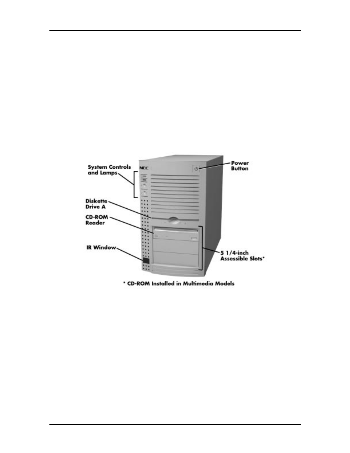
Figure 1-1 shows the front panel features and the locations of the accessible storage devices
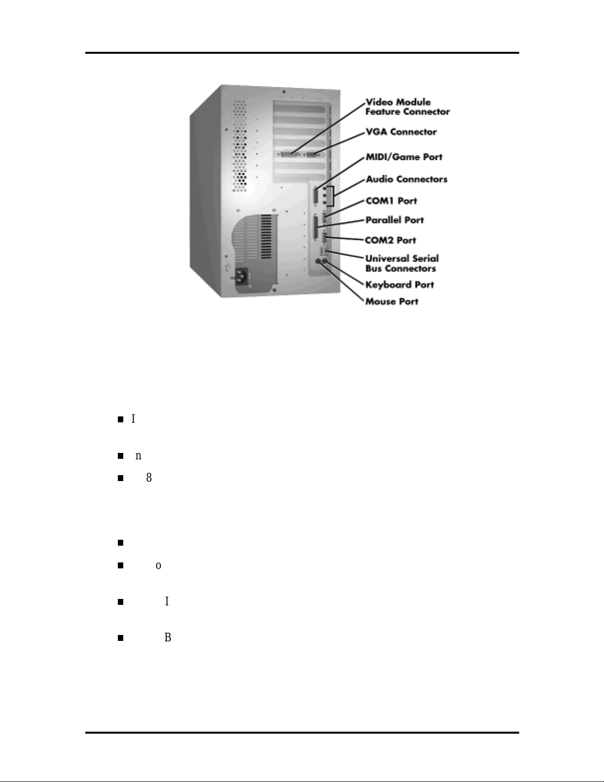
in a system. Figure 1-2 shows the features on the rear panel of the system chassis.
Figure 1-1 System Controls and Storage Device Slots
Technical Information 1-3
Figure 1-2 Rear Panel Features
SYSTEM BOARD
Key features of the system board include the following:
Intel Pentium Pro microprocessor running at 200- or 180-MHz (model
dependent)
Intel 82440FX PCI chipset used for PCI/ISA, memory, and peripheral control
PC87307 Super I/O controller (integrates standard PC I/O functions: two serial
ports, one EPP/ECP-capable parallel port, floppy disk interface, real time clock,
CMOS RAM, keyboard controller, and support for an IrDA-compatible infrared
interface)
PCI and ISA peripheral connectors on the system board
Support for up to 256 MB of 60 nanosecond (ns) single in-line memory modules
(SIMMs)
AMI BIOS in a flash memory device (2-MB Intel PA28FB200BX) supports
system setup and PCI auto-configuration
Sound Blaster Pro-compatible Crystal CS4236 audio chip

1-4 Technical Information
Expansion slots for up to five add-in boards
Three dedicated PCI slots
Three dedicated ISA-bus slots
One “combination” slot for either a PCI or an ISA add-in board
200 watt power supply (switch-selectable for 115 and 230 V ac operation)
Two RS-232C-compatible 9-pin serial connectors
Two Universal Serial Bus (USB) ports
One multimode, 25-pin Centronics®-compatible parallel port
Two peripheral bays:
Drive bay that holds up to three 3.5-inch drives (one externally-accessible,
two internal access only)
Device bay for installing externally accessible 5.25-inch devices (up to three
half-height drives or one half-height plus one full-height drive)
One 1.44 MB, 3.5-inch high-density diskette drive installed
PS/2®-style keyboard and mouse connector
Speaker mounted on the system board
Password protection and padlock slot for system security
Hardware monitoring using an Intel Heceta ASIC chip (see LANDesk Client
Manager later in this section for more information)
Table 1-1 lists the major chips on the system board. Information on system board connector
pin assignments and switch settings is provided in the PowerMate Pro2200/2180 Service
and Reference Manual (document number 819-181519-000).

Technical Information 1-5
g
y
g
g
g
y sy
g
g
y
g
y
g
g
Table 1-1 System Board Feature Components
Chip Function
Pentium Chip 200/66-MHz or 180/60-MHz Intel Pentium Pro
processor
82440FX Chipset:
82371SB PCI/ISA IDE
Xccelerator (PIIX3)
82441FX PCI Brid
Memor
82442FX Data Bus Accelerator
(DBX)
PC87307 I/O Controller Multimode parallel port
Controller (PMC)
e and
Provides interface between PCI and ISA bus
Supports up to four PCI/IDE devices
Mode 3 and mode 4 support; Lo
addressin
Head Sector (ECHS) translation modes and
ATAPI devices on both IDE interfaces
Provides CPU interface control and inte
DRAM control, supports a full
PCI bus interface plus CPU-to-DRAM and
PCI-to-DRAM data bufferin
Connects to the CPU data bus, memory data
bus, and PMC private data bus; works in
parallel with PMC to provide a hi
performance memor
Pro-based systems.
Centronics compatible (standard mode)
Enhanced capabilities port (ECP)
Enhanced parallel port (EPP)
Two RS-232C serial ports that support an IrDA
and Consumer IR compliant Infrared interface
Inte
calendar functionality and 242-byte batterybacked CMOS RAM
Inte
Flexible IRQ and DMA mappin
Windows 95
Supports industry-standard floppy controller
(LBA) and Extended Cylinder
rated real-time clock with Centur
rated 8042 keyboard controller
ical block
rated
nchronous
h
subsystem for Pentium
to support
Processor and Secondary Cache
The PowerMate Pro2200 uses a 200-MHz Pentium processor with an internal clock speed
of 200 MHz. The PowerMate Pro2180 uses a 180-MHz Pentium processor with an internal
clock speed of 180 MHz. (The external speed of the 200-MHz processor is 66 MHz, while
the 180-MHz processor has an external speed of 60-MHz.)
Each processor has 16 KB of write-back primary cache and a math coprocessor. The 16 KB
primary cache provides 8 KB for instructions and 8 KB for data.

1-6 Technical Information
The processor is an advanced pipelined 32-bit addressing, 64-bit data processor designed to
optimize multitasking operating systems. The 64-bit registers and data paths support 64-bit
addresses and data types.
To use the Pentium Pro processor’s power, the system features an optimized 64-bit memory
interface and 256 KB of secondary write-back cache incorporated into the processor.
The processor is compatible with 8-, 16-, and 32-bit software written for the Intel386™,
Intel486™, and Pentium Pro processors. The Pentium Pro processor is mounted into a
socket-8 zero insertion force (ZIF) socket. The socket provides an upgrade path to the next
generation processor.
System BIOS
The system BIOS is from American Megatrends Incorporated (AMI), which provides ISA
and PCI compatibility. The BIOS is contained in a flash memory device on the system board
(2-MB Intel PA28FB200BX). The BIOS provides the power-on self test (POST), the
system Setup program, a PCI and IDE auto-configuration utility, and BIOS recovery code.
The system BIOS is always shadowed. Shadowing allows any BIOS routine to be executed
from fast 32-bit onboard DRAM instead of from the slower 8-bit flash device.
NECCSD’s Flash ROM allows fast, economical BIOS upgrades. NEC Flash ROMs are
reprogrammable system and video EPROMs. With NECCSD’s Flash ROM, a ROM BIOS
change:
is fast and easily done using a Flash utility
eliminates the expensive replacement of ROM BIOS chips, and reduces system
maintenance costs
reduces inadvertent system board damage that can take place when replacing
ROMs
facilitates adopting new technology while maintaining corporate standards
gives network administrators company-wide control of BIOS revisions.
The BIOS programs execute the Power-On Self-Test, initialize processor controllers, and
interact with the display, diskette drives, hard disks, communication devices, and
peripherals. The system BIOS also contains the Setup utility. The hardware setup default
copies the ROM BIOS into RAM (shadowing) for maximum performance.
The Flash ROM allows the system and video BIOS to be upgraded with the BIOS Update
utility, without removing the ROM (see Section 2 of the PowerMate Pro2200/2180 Service
and Reference Manual for further information on the BIOS Update utility). The Flash
ROM supports the reprogramming of the system BIOS and the video BIOS.

Technical Information 1-7
The system memory map in shown in Table 1-2.
Table 1-2 System Memory Map
Memory Space Size Function
100000-8000000 130048 KB Extended memory (configurable/upgradable)
E0000-FFFFF 64 KB AMI System BIOS
EC000-EFFFF 16 KB FLASH boot block (available as UMB)
EA000-EBFFF 8 KB ECSD (Plug and Play configuration area)
E9000-E9FFF 4 KB Reserved for BIOS
E8000-E8FFF 4 KB OEM logo (available as UMB)
E0000-E7FFF 32 KB BIOS reserved (currently available as UMB)
C8000-DFFFF 96 KB Available HI DOS memory (open to ISA and PCI
bus)
A0000-C7FFF 160 KB Available HI DOS memory (normally reserved for
Video BIOS)
9FC00-9FFFF 1 KB Extended BIOS data
80000-9FBFF 127 KB Extended conventional
00000-7FFFF 512 KB Conventional base memory
I/O Addressing
The processor communicates with I/O devices by I/O mapping. The hexadecimal (hex)
addresses of I/O devices are listed in Table 1-3.
Table 1-3 I/O Address Map
Address (Hex) I/O Device Name
0000-000F PIIX3 - DMA controller 1 (channel 0-3)
0020-0021 PIIX3 - Interrupt controller 1
002E-002F 87308B I/O base configuration registers
0040-0043 PIIX3 - Timer 1
0048-004B PIIX3 - Timer 2
0060 Keyboard controller byte - Reset IRQ
0061 PIIX3 - NMI, speaker control

1-8 Technical Information
Address (Hex) I/O Device Name
0064 Keyboard controller, command/status byte
0070, bit 7 PIIX3 - Enable NMI
0070, bits 6 through 0 PIIX3 - Real time clock, address
0071 PIIX3 - Real time clock, data
0078-0079 Reserved - board configuration
0080-008F PIIX3 - DMA page registers
00A0-00A1 PIIX3 - Interrupt controller 2
00C0-00DE PIIX3 - DMA controller 2
00F0 Reset numeric error (numeric data processor)
0170-0177 Secondary IDE channel
01F0-01F7 Primary IDE channel
Table 1-3 I/O Address Map
0200-0207 Game port
0220-022F CS4236 audio
0278-027F Parallel port 2
02F8-02FF On-board serial port 2
0330-0331 MPU-401 (MIDI)
0376 Secondary IDE channel command port
0377 Secondary IDE channel status port
0378-037F Parallel port 1
0388-038B CS4236 audio
03BC-03BF Parallel port 3
03E8-03EF Serial port 3
03F0-03F5 Floppy channel 1
03F6 Primary IDE channel command port
03F7 (write) Floppy channel 1 command
03F7, bit 7 Floppy disk change channel 1
03F7, bit 6 through 0 Primary IDE channel status port
03F8-03FF On-board serial port 1
04D0-04D1 Edge/level triggered
LPT + 400h ECP port, LPT + 400h
0608-060B CS4236 audio
0CF8* PCI configuration address register

Technical Information 1-9
Table 1-3 I/O Address Map
Address (Hex) I/O Device Name
0CF9 Turbo and reset control register
0CFC-0CFF* PCI configuration data register
FF00-FF07 IDE bus master register
FFA0-FFA7 IDE primary channel
0FF0-0FF7 CS4236 audio
* Only accessible by DWORD accesses.
System Memory
Configurations ship with 16 MB of memory (32 MB in the SCSI configuration): 640 KB of
base memory and 15 MB (31 MB in the SCSI configuration) of extended memory. System
memory can be expanded up to 256 MB, using optional single in-line memory modules
(SIMMs) installed in SIMM sockets on the system board.
The memory configuration consists of two banks (bank 0 and bank 1) with two sockets
each. The SIMM memory sockets accept 32-bit (non-parity) 4-, 8-, 16-, 32-, or 64-MB,
60 ns, Extended Data Out (EDO) mode SIMMs.
NOTE:
64-MB SIMMs have not been qualified
for use, but they will be supported by the system
board when they become available.
The SIMMs are 1 MB x 32 bit (4 MB), 2 MB x 32 bit (8 MB), 4 MB x 32 bit (16 MB),
8 MB x 32 bit (32 MB), and 16 MB x 32 bit (64 MB). When the standard SIMMs are
removed, four 64-MB SIMMs may be installed for a total of 256 MB.
CAUTION:
SIMMs must match the tin metal
plating used on the system board SIMM sockets.
When adding SIMMs, use tin-plated SIMMs.
SIMMs install directly in the four sockets on the system board. The four sockets are
assigned as Bank 0 (2 sockets) and Bank 1 (2 sockets). All configurations have two SIMMs
installed in bank 1. SIMM banks can be populated in either order.

1-10 Technical Information
SIMMs must be installed in pairs of the same memory type and size. Both sockets must be
populated within a bank for the system to work. No switch or jumpers required setting
when the memory is changed. The system BIOS automatically detects the SIMMs. See
“Checking the Memory in the System” in Section 3 of the PowerMate Pro2200/2180
Service and Reference Manual for the valid configurations.
Interrupt Controller
The interrupt controller operates as an interrupt manager for the entire system environment.
The controller accepts requests from peripherals, issues interrupt requests to the processor,
resolves interrupt priorities, and provides vectors for the processor to determine which
interrupt routine to execute. The interrupt controller has priority assignment modes that can
be reconfigured at any time during system operations.
The interrupt levels are described in Table 1-4. Interrupt-level assignments 0 through 15 are
in order of decreasing priority. See Section 2 of the PowerMate Pro2200/2180 Service and
Reference Manual for information on changing the interrupts using the Setup Utility.
Table 1-4
Interrupt Assignment
BASE System Multimedia System SCSI System
0 System Timer System Timer System Timer
1 Keyboard Keyboard Keyboard
2 (9) Available Sound (internal on MM systems)
MIDI I/O
3 Serial Port B - Com2 Serial Port B - Com2 USB Serial Port
4 Serial Port A - Com1 Serial Port A - Com1
5 Available Sound (internal on MM systems)
Sound Blaster
6 Floppy Disk Floppy Disk Floppy Disk
7 Parallel Port - LPT1 Parallel Port - LPT1 Parallel Port - LPT1
8 Clock/Calendar Clock/Calendar Clock/Calendar
10 USB Serial Port USB Serial Port SCSI adapter
IRQ Assignments
Sound (internal on MM systems)
MIDI I/O
Serial Port A - Com1 (shared)
Serial Port B - Com2 (shared)
Sound (internal on MM systems)
Sound Blaster
11 Video Adapter Video Adapter Video Adapter
12 Mouse Mouse Mouse
13 Coprocessor Coprocessor Coprocessor
14 IDE port A IDE port A IDE port A
15 IDE port B IDE port B IDE port B

Technical Information 1-11
The PowerMate Pro2200/2180 multimedia models and SCSI multimedia models do not
have any free IRQs. Disable the USB connectors to add an additional adapter.
Plug and Play
The system comes with a Plug and Play BIOS which supports Plug and Play technology.
Plug and Play eliminates complicated setup procedures for installing Plug and Play
expansion boards. With Plug and Play, adding a Plug and Play expansion board is done by
turning off the system, installing the board, and turning on the system. There are no jumpers
to set and no system resource conflicts to resolve. Plug and Play automatically configures
the board.
ISA Bus
The system board uses the ISA bus for transferring data between the processor and I/O
peripherals and expansion boards. The ISA bus supports 16-bit data transfers and typically
operates at 8 MHz. ISA expansion slot connector pin assignments are provided in
Appendix A of the PowerMate Pro2200/2180 Service and Reference Manual.
PCI Local Bus
The 32-bit PCI-bus is the primary I/O bus for the system. The PCI-bus is a highly-integrated
I/O interface that offers the highest performance local bus available for the Pentium Pro
processor. The bus supports burst modes that send large chunks of data across the bus,
allowing fast displays of high-resolution images.
The PCI-bus operates at half the Pentium Pro’s processor speed, and supports memory
transfer rates of up to 105 MB per second for reads and up to 120 MB per second for
writes, depending on processor configuration.
The high-bandwidth PCI-bus eliminates the data bottleneck found in traditional systems,
maintains maximum performance at high clock speeds, and provides a clear upgrade path to
future technologies.
PCI expansion slot connector pin assignments are provided in Appendix A of the
PowerMate Pro2200/2180 Service and Reference Manual.
PCI/IDE Ports
The system board provides two high-performance PCI/IDE ports: a primary channel and a
secondary channel. Each port supports up to two devices for a total of four IDE devices.
The primary PCI/IDE port has an enhanced IDE interface which supports PIO Mode 4
devices with 16 MB per second 32-bit wide data transfers on the high-performance PCI
local bus. The installed hard disk drive is connected to the primary PCI/IDE port. In
multimedia configurations, the installed CD-ROM reader is connected to the secondary
PCI/IDE port.

1-12 Technical Information
Parallel Interface
The system has a 25-pin parallel bidirectional enhanced parallel port on the system board.
Port specifications conform to the IBM-PC standards. The port supports Enhanced
Capabilities Port (ECP) and Enhanced Parallel Port (EPP) modes for devices that require
ECP or EPP protocols. The protocols allow high-speed bidirectional transfer over a parallel
port and increase parallel port functionality by supporting more devices.
The BIOS has automatic ISA printer port sensing. If the BIOS detects an ISA printer port
mapped to the same address, the built-in printer port is disabled. The BIOS also sets the
first parallel interface port it finds as LPT1 and the second port it finds as LPT2. The
interrupt is selected to either IRQ5 or IRQ7 via Setup. Software selectable base addresses
are 3BCh, 378h, and 278h.
I/O addresses and interrupts for the parallel port are given in Table 1-5.
NOTE:
parallel port are not available for ISA parallel
ports.
Any interrupts used for the built-in
Table 1-5 Parallel Port Addressing and Interrupts
Starting I/O Address Interrupt Level Port
378 IRQ05 LPT1
278 IRQ05 LPT1 or LPT2
3BC IRQ05 LPT1 or LPT2
378 IRQ07 LPT1
278 IRQ07 LPT1 or LPT2
3BC IRQ07 LPT1 or LPT2
Parallel interface signals are output through the system board’s 25-pin, D-subconnector.
The connector is located at the rear of the system unit. Pin locations for the parallel
interface connector are given in Appendix A of the PowerMate Pro2200/2180 Service and
Reference Manual.
Serial Interface
The system has two 16C550 UART compatible serial ports (COM1 and COM2) integrated
on the I/O controller. The serial ports support the standard RS-232C interface and the IR
interface (see Table 1-6). The buffered high-speed serial ports supports transfer rates up to
19.2 KB. These ports allow the installation of high-speed serial devices for faster data
transfer rates.
Technical Information 1-13
I/O addresses and interrupt levels for the two channels are given Table 1-6. The interrupt
level is selectable via Setup to either IRQ3 or IRQ4. Software selectable base addresses are
3F8h, 2F8h, 3E8h, and 2E8h.
NOTE: Any interrupts used for the built-in
serial ports are not available for ISA parallel
ports.
Table 1-6 Serial Port Addressing and Interrupts
Starting I/O Address Interrupt Level Port
3F8h IRQ04 COM1
2F8h IRQ03 COM2*
3E8h IRQ04 COM3
2E8h IRQ03 COM4
* Used for IrDA data transfer
See Section 2 of the PowerMate Pro2200/2180 Service and Reference Manual for
information on resetting the port through the Setup Utility.
Serial interface specifications include:
Baud rate up to 19.2 KB per second
Word length - 5, 6, 7, or 8 bits
Stop bit - 1, 1.5, or 2 bits
Start bit - 1 bit
Parity bit - 1 bit (odd parity or even parity).
Serial interface signals are output through the system board’s 9-pin, D-subconnector. The
connectors are located at the rear of the system unit. Pin locations for the serial interface
connector are shown in Appendix A of the PowerMate Pro2200/2180 Service and
Reference Manual.
USB Interface
The Universal Serial Bus (USB) port allows you to add new plug and play serial devices
without opening up the system. You simply plug the devices into the port. The USB
determines system resources for each peripheral and assigns them without user intervention.
Up to 127 devices can be daisy chained to a single computer.
 Loading...