


PROPRIETARY NOTICE AND LIABILITY DISCLAIMER
The information disclosed in this document, including all designs and related materials, is
the valuable property of NEC Corporation (NEC) and/or its licensors. NEC and/or its licensors, as appropriate, reserve all patent, copyright and other proprietary rights to this document, including all design, manufacturing, reproduction, use, and sales rights thereto, except
to the extent said rights are expressly granted to others.
The NEC product(s) discussed in this document are warranted in accordance with the terms
of the Warranty Statement accompanying each product. However, actual performance of
each such product is dependent upon factors such as system configuration, customer data,
and operator control. Since implementation by customers of each product may vary, the
suitability of specific product configurations and applications must be determined by the
customer and is not warranted by NEC.
To allow for design and specification improvements, the information in this document is
subject to change at any time, without notice. Reproduction of this document or portions
thereof without prior written approval of NEC is prohibited.
MultiSync and PowerMate are U.S. registered trademarks of NEC Technologies, Inc.
FastFacts and NEC SVGA, are U.S. trademarks of NEC Technologies, Inc.
All other product, brand, or trade names used in this publication are the trademarks or registered
trademarks of their respective trademark owners.
First Printing — June 1994
Copyright 1994 Copyright 1994
NEC Technologies, Inc. NEC Corporation
1414 Massachusetts Avenue 7-1 Shiba 5-Chome, Minato-Ku
Boxborough, MA 01719 Tokyo 108-01, Japan
All Rights Reserved All Rights Reserved

Contents
Page
Preface............................................................................................................................. xi
Abbreviations .................................................................................................................. xiii
Section 1 Technical Information
Desktop System Unit......................................................................................................1-1
Minitower System Unit...................................................................................................1-2
System Board.............................................................................................................1-2
Processor................................................................................................................1-4
Secondary Cache ....................................................................................................1-5
Flash ROM .............................................................................................................1-5
Power Management ................................................................................................1-6
I/O Addressing........................................................................................................1-7
System Memory......................................................................................................1-8
Interrupt Controller.................................................................................................1-9
Video Controller...................................................................................................1-10
Video Memory...................................................................................................... 1-10
ISA/PCI-Bus Backboard...........................................................................................1-12
ISA Bus................................................................................................................1-12
PCI Local Bus ......................................................................................................1-12
PCI Auto Configuration........................................................................................1-12
Parallel Interface.......................................................................................................1-13
Serial Interface .........................................................................................................1-14
Indicator Panel..........................................................................................................1-14
Power Supply............................................................................................................... 1-15
Diskette Drive ..............................................................................................................1-15
Hard Disk Drive ...........................................................................................................1-15
Keyboard...................................................................................................................... 1-15
iii
Section 2 Setup and Operation
Unpacking and Repacking ..............................................................................................2-1
Setup..............................................................................................................................2-1
Desktop Setup............................................................................................................2-2
Minitower Setup.........................................................................................................2-5
System Configuration .....................................................................................................2-7
Setup Utility...............................................................................................................2-8
How to Start Setup.....................................................................................................2-8

iv Contents
How to Use Setup......................................................................................................2-9
Standard CMOS Setup..........................................................................................2-10
Advanced CMOS Setup........................................................................................2-11
Peripheral Management Setup...............................................................................2-14
Configure With BIOS Defaults.............................................................................. 2-15
Configure With Power-On Defaults.......................................................................2-15
Change Password.................................................................................................. 2-15
Write to CMOS and Exit.......................................................................................2-16
Do Not Write to CMOS and Exit..........................................................................2-16
System Board Jumpers .................................................................................................2-17
Section 3 Options
Internal Options .............................................................................................................. 3-1
Desktop Cover Removal.............................................................................................3-2
Minitower Cover Removal .......................................................................................... 3-3
Minitower Bottom Cover Removal.............................................................................3-4
Expansion Board(s)....................................................................................................3-5
Desktop Expansion Board Installation ..................................................................... 3-5
Minitower Expansion Board Installation..................................................................3-8
Expansion Board Troubleshooting ..........................................................................3-9
System Board Options.............................................................................................. 3-10
OverDrive Processor Installation...........................................................................3-11
OverDrive Processor Troubleshooting...................................................................3-13
SIMM Memory Installation...................................................................................3-13
SIMM Upgrade Path............................................................................................. 3-14
SIMM Installation.................................................................................................3-17
SIMM Upgrade Kit Troubleshooting.....................................................................3-18
Video DRAM Chip Installation.............................................................................3-19
Video DRAM Chip Troubleshooting.....................................................................3-20
Optional 5 1/4-Inch Slot Devices..................................................................................3-21
5 1/4-Inch Diskette Drive..........................................................................................3-21
5 1/4-Inch Diskette Drive Settings............................................................................3-21
Hard Disk Drives......................................................................................................3-22
Hard Disk Drive Settings.......................................................................................... 3-23
Desktop 5 1/4-Inch Device Installation .........................................................................3-24
Desktop 3 1/2-inch Drive Bracket Removal..............................................................3-24
Desktop Blank Panel Removal..................................................................................3-25
Desktop 5 1/4-Inch Device Placement.......................................................................3-26
Desktop 5 1/4-Inch Diskette Drive Cabling...............................................................3-27
Desktop Hard Disk Drive Cabling ............................................................................. 3-28
Finishing Desktop 5 1/4-Inch Device Installation.......................................................3-29

Contents v
Minitower 5 1/4-Inch Device Installation......................................................................3-29
Minitower Blank Panel Removal...............................................................................3-30
Minitower 5 1/4-Inch Device Cage Removal.............................................................3-31
Minitower 5 1/4-Inch Device Placement....................................................................3-33
Minitower 3 1/2-Inch Drive Installation ........................................................................3-33
Minitower 3 1/2-Inch Drive Cage Removal...............................................................3-34
Minitower 3 1/2-Inch Drive Placement......................................................................3-35
Minitower 5 1/4-Inch Diskette Drive Cabling............................................................3-36
Minitower Hard Disk Drive Cabling.......................................................................... 3-37
Finishing Minitower 5 1/4-Inch Device and 3 1/2-Inch Drive Installation................... 3-38
Device Troubleshooting............................................................................................3-39
NEC SVGA Monitor....................................................................................................3-40
Connecting the Monitor............................................................................................3-41
Front Control Panel..................................................................................................3-43
Rear Control Panel ................................................................................................... 3-44
NEC SVGA Monitor Troubleshooting ...................................................................... 3-45
Section 4 Maintenance and Troubleshooting
Maintenance...................................................................................................................4-2
Routine Checks ..........................................................................................................4-2
System Unit................................................................................................................4-2
Keyboard....................................................................................................................4-3
Mouse........................................................................................................................4-4
Troubleshooting .............................................................................................................4-5
Error Messages...........................................................................................................4-5
Diagnosing and Solving Problems...............................................................................4-7
Beep Codes..............................................................................................................4-11
BIOS Update Utility..................................................................................................... 4-12
Recovery Mode............................................................................................................ 4-13
Section 5 Desktop Repair
Disassembly and Reassembly ..........................................................................................5-1
Top Cover Removal ...................................................................................................5-2
Expansion Board Removal .......................................................................................... 5-3
ISA/PCI-Bus Backboard Removal..............................................................................5-5
3 1/2-inch Diskette and Hard Disk Drive Removal......................................................5-6
Front Panel Assembly Removal ................................................................................... 5-7
Power Button Cover Removal....................................................................................5-9
Speaker Assembly Removal...................................................................................... 5-10
SIMM Removal........................................................................................................5-11
Optional 5 1/4-Inch Device Removal ........................................................................5-12

vi Contents
5 1/4-Inch Device Cage Removal..............................................................................5-13
Power Supply Removal.............................................................................................5-14
System Board Removal.............................................................................................5-15
Illustrated Parts Breakdown ...................................................................................... 5-17
Section 6 Minitower Repair
Disassembly and Reassembly ..........................................................................................6-1
Top Cover Removal ...................................................................................................6-3
Bottom Cover Removal..............................................................................................6-4
Expansion Board Removal .......................................................................................... 6-5
Front Panel Assembly Removal ................................................................................... 6-6
Power Button Cover Removal....................................................................................6-7
Blank Panel and Metal Cover Plate Removal...............................................................6-7
Speaker Assembly Removal........................................................................................6-9
SIMM Removal........................................................................................................6-10
5 1/4-Inch Device Cage Removal..............................................................................6-11
5 1/4-Inch Device Removal....................................................................................... 6-12
3 1/2-inch Hard Disk Drive Removal ........................................................................ 6-13
3 1/2-inch Diskette Drive Removal ........................................................................... 6-15
Power Supply Removal.............................................................................................6-17
ISA/PCI-BUS Backboard Removal...........................................................................6-19
System Board Removal.............................................................................................6-20
Illustrated Parts Breakdown ...................................................................................... 6-22
Appendix A Connector Pin Assignments
Serial Interface Connectors............................................................................................A-3
Parallel Interface Connector........................................................................................... A-4
VGA Interface Connector Pin Assignments.................................................................... A-5
Speaker Connector Pin Assignments.............................................................................. A-5
Power Supply Connectors.............................................................................................. A-6
Keyboard and Mouse Connectors.................................................................................. A-6
Power Lamp Connector.................................................................................................A-6
Hard Disk Drive Busy Lamp Connector ......................................................................... A-7
Fan Connector............................................................................................................... A-7
Reset Button Connector ................................................................................................ A-7
Diskette Drive Interface Pin Assignments....................................................................... A-8
IDE Interface Connectors.............................................................................................. A-9
SIMM Sockets ............................................................................................................ A-10
ISA/PCI-Bus Backboard Connector Pin Assignments.................................................. A-11
ISA Expansion Bus Connector Pin Assignments .......................................................... A-13
PCI Expansion Bus Connector Pin Assignments .......................................................... A-15

Contents vii
Appendix B Specifications
System Unit Specifications............................................................................................. B-1
Power Supply Specifications.......................................................................................... B-3
Diskette Drive Specifications......................................................................................... B-4
Hard Disk Specifications................................................................................................ B-5
NEC SVGA Monitor Specifications............................................................................... B-6
List of Figures
1-1 PowerMate Desktop System Unit Features..........................................................1-1
1-2 PowerMate Minitower System Unit Features ......................................................1-2
2-1 Desktop Voltage Selector Switch........................................................................2-2
2-2 Desktop Peripheral Connections..........................................................................2-3
2-3 Desktop Lamps, Reset Button, and Power Button ............................................... 2-3
2-4 Minitower Voltage Selector Switch ..................................................................... 2-5
2-5 Minitower Peripheral Connections.......................................................................2-6
2-6 Minitower Indicators, Reset Button, and Power Button.......................................2-6
2-7 System Board Jumpers......................................................................................2-17
3-1 Desktop Cover Screws........................................................................................3-2
3-2 Removing the Desktop Cover .............................................................................3-2
3-3 Minitower Cover Screws.....................................................................................3-3
3-4 Removing the Minitower Cover ..........................................................................3-4
3-6 Desktop Expansion Slots.....................................................................................3-6
3-7 Inside Expansion Slot Screw...............................................................................3-6
3-8 Removing the Inside Expansion Slot Bracket ......................................................3-7
3-9 Minitower Expansion Slots .................................................................................3-8
3-10 System Board Option Sockets...........................................................................3-10
3-11 PGA/OverDrive Socket Lever ........................................................................... 3-11
3-12 OverDrive Processor Alignment........................................................................3-12
3-13 3 1/2-Inch Drive Bracket Screws.......................................................................3-17
3-14 SIMM Installation.............................................................................................3-17
3-15 Video DRAM Chip Socket................................................................................3-19
3-16 OSDA-90C, 1.44-MB Diskette Drive................................................................ 3-21
3-17 FD1158C, 1.2-MB Diskette Drive.....................................................................3-22
3-18 WDAC1270/2340/2420 270-, 340-, and 420-MB Hard Disk Drives..................3-23
3-19 3 1/2-Inch Drive Bracket Screws.......................................................................3-24
3-20 Indicator Panel Connectors ............................................................................... 3-25
3-21 Desktop Blank Panel Removal .......................................................................... 3-26
3-22 Desktop 5 1/4-Inch Device Screws....................................................................3-27
3-23 Desktop 5 1/4-Inch Diskette Drive Cables.........................................................3-28
3-24 Desktop Hard Disk Drive Cables....................................................................... 3-29

viii Contents
3-25 Removing the Front Panel Screws.....................................................................3-30
3-26 Minitower Blank Panel Removal .......................................................................3-31
3-27 Removing the Device Cage Screws...................................................................3-32
3-28 Minitower 5 1/4-Inch Device Screws.................................................................3-33
3-29 Removing 3 1/2-Inch Drive Cage Screws..........................................................3-34
3-30 Securing the Drive in the 3 1/2-Inch Drive Cage................................................ 3-35
3-31 Minitower 5 1/4-Inch Diskette Drive Cables ...................................................... 3-36
3-32 Minitower Hard Disk Drive Cables....................................................................3-37
3-33 Monitor Connections ........................................................................................3-42
3-34 NEC SVGA Monitor Front Control Panel.........................................................3-43
3-35 NEC SVGA Monitor Rear Control Panel.......................................................... 3-44
4-1 Removing the Keyboard Enclosure......................................................................4-3
4-2 Removing the Mouse Ball Cover.........................................................................4-4
5-1 Top Cover Screws ..............................................................................................5-3
5-2 Removing the Top Cover....................................................................................5-3
5-3 Expansion Slot Screw .........................................................................................5-4
5-4 Inside Expansion Slot Screw...............................................................................5-4
5-5 Removing the Expansion Slot L-Bracket.............................................................5-5
5-6 ISA/PCI-Bus Backboard Screws.........................................................................5-5
5-7 3 1/2-Inch Drive Bracket Screws.........................................................................5-6
5-8 3 1/2-Inch Diskette and Hard Disk Drive Screws.................................................5-7
5-9 Indicator Panel Connectors .................................................................................5-8
5-10 Power Button Tabs.............................................................................................5-9
5-11 Speaker Screw.................................................................................................. 5-10
5-12 SIMM Socket...................................................................................................5-11
5-13 5 1/4-Inch Device Screws..................................................................................5-12
5-14 5 1/4-Inch Device Cage Screws......................................................................... 5-13
5-15 Power Button Screws .......................................................................................5-14
5-16 Power Supply Screws .......................................................................................5-15
5-17 System Board Connectors and Screws ..............................................................5-16
5-18 PowerMate P60 Desktop Illustrated Parts Breakdown ...................................... 5-18
6-1 Minitower Cover Screws.....................................................................................6-3
6-2 Removing the Minitower Cover ..........................................................................6-4
6-3 Minitower Bottom Access Cover ........................................................................6-5
6-4 Expansion Slot Screw .........................................................................................6-5
6-5 Front Panel Screws .............................................................................................6-6
6-6 Power Button Tabs.............................................................................................6-7
6-7 Blank Panel Removal ..........................................................................................6-8
6-8 Speaker Tabs ......................................................................................................6-9
6-9 SIMM Socket...................................................................................................6-10
6-10 Removing the Device Cage Screws...................................................................6-11
6-11 5 1/4-Inch Device Screws..................................................................................6-12

Contents ix
6-12 3 1/2-Inch Hard Disk Drive Cables .................................................................... 6-13
6-13 Removing 3 1/2-Inch Drive Cage Screws..........................................................6-14
6-14 3 1/2-Inch Hard Disk Drive Screws...................................................................6-14
6-15 3 1/2-Inch Diskette Drive Cables ....................................................................... 6-15
6-16 Diskette Drive Bracket Screws.......................................................................... 6-16
6-17 Diskette Drive Screws....................................................................................... 6-16
6-18 Power Button Screws .......................................................................................6-17
6-19 Power Supply Screws .......................................................................................6-18
6-20 Chassis Support Bracket Screws.......................................................................6-19
6-21 ISA/PCI-Bus Backboard Screws.......................................................................6-20
6-22 System Board Connectors and Screws ..............................................................6-21
6-23 PowerMate P60 Minitower Illustrated Parts Breakdown ...................................6-24
A-1 System Board Layout......................................................................................... A-1
A-2 Serial Interface (P11/P12)..................................................................................A-3
A-3 Parallel Interface (P10)....................................................................................... A-4
A-4 Power Supply Connector (J12) Pin Assignments ................................................ A-6
List of Tables
1-1 System Board Chips............................................................................................1-4
1-2 System Memory Map..........................................................................................1-6
1-3 I/O Address Map ................................................................................................1-7
1-4 Interrupt Level Assignments................................................................................1-9
1-5 Video Resolutions and Frequencies...................................................................1-10
1-6 Parallel Port Addressing and Interrupts .............................................................1-13
1-7 Serial Port Addressing and Interrupts................................................................ 1-14
2-1 Standard CMOS Setup Parameters.................................................................... 2-11
2-2 Advanced CMOS Setup Parameters.................................................................. 2-12
2-3 Peripheral Management Setup Parameters.........................................................2-14
2-4 System Configuration Jumpers..........................................................................2-18
3-1 Expansion Board Problems and Solutions............................................................3-9
3-2 OverDrive Problems and Solutions....................................................................3-13
3-3 Desktop SIMM Configurations.........................................................................3-15
3-4 Minitower SIMM Configurations......................................................................3-16
3-5 SIMM Upgrade Problems and Solutions............................................................3-18
3-6 Video DRAM Chip Problems and Solutions...................................................... 3-20
3-7 Optional 5 1/4-Inch Device Problems and Solutions ..........................................3-39
3-8 NEC SVGA Monitor Problems and Solutions ...................................................3-45

x Contents
4-1 NEC Service and Information Telephone Numbers..............................................4-1
4-2 System Error Messages.......................................................................................4-5
4-3 ISA NMI Error Messages ...................................................................................4-7
4-4 Problems and Solutions.......................................................................................4-7
4-5 Diagnostic Beep Codes.....................................................................................4-11
5-1 PowerMate P60 Desktop Disassembly Sequence.................................................5-1
5-2 Connector Identifiers.........................................................................................5-16
5-3 PowerMate P60 Desktop Field-Replaceable Parts List.......................................5-17
5-4 PowerMate P60 Desktop Options.....................................................................5-19
5-5 PowerMate P60 Desktop Documentation and Packaging...................................5-20
6-1 PowerMate P60 Minitower Disassembly Sequence .............................................. 6-1
6-2 Connector Identifiers.........................................................................................6-21
6-3 PowerMate P60 Minitower Field-Replaceable Parts List ...................................6-22
6-4 PowerMate P60 Minitower Options..................................................................6-25
6-5 PowerMate P60 Minitower Documentation and Packaging ...............................6-26
A-1 System Board Connector Descriptions ............................................................... A-2
A-2 Video Connector (P8) Pin Assignments .............................................................. A-5
A-3 Speaker Connector (P6) Pin Assignments........................................................... A-5
A-4 Keyboard (P1) And Mouse (P2) Connector Pin Assignments.............................. A-6
A-5 Power Lamp Connector (P5) Pin Assignments ................................................... A-6
A-6 Hard Disk Drive Lamp Connector (P7) Pin Assignments.................................... A-7
A-7 Fan Connector (P5) Pin Assignments ................................................................. A-7
A-8 Reset Button Connector (P5) Pin Assignments................................................... A-7
A-9 Diskette Drive Connector (P13) Pin Assignments...............................................A-8
A-10 IDE Connector Pin Assignments (P8/P14).......................................................... A-9
A-11 SIMM Socket Pin Assignments........................................................................ A-10
A-12 ISA/PCI-Bus Backboard Connector Pin Assignments....................................... A-11
A-13 ISA Expansion Slot Pin Assignments................................................................ A-13
A-14 PCI Expansion Slot Pin Assignments................................................................ A-15
B-1 System Unit Specifications................................................................................. B-1
B-2 Power Supply Input Requirements ..................................................................... B-3
B-3 Power Supply Output Specifications .................................................................. B-3
B-4 Specifications for Diskette Drives ....................................................................... B-4
B-5 Specifications for 270-, 340-, and 420-MB Hard Disk Drives............................. B-5
B-6 NEC SVGA Monitor Specifications ................................................................... B-6

Preface
This service and reference manual contains the technical information necessary to set up,
maintain, troubleshoot, and repair the NEC PowerMate P60D, and PowerMate P60M
computer systems. It also provides hardware and interface information for users who
need an overview of the computer system design. The manual is written for NEC-trained
customer engineers, system analysts, service center personnel, and dealers.
The manual is organized as follows:
Section 1, Technical Information, provides an overview of the computer features, hard-
ware design, interface ports and internal devices.
Section 2, Setup and Operation, takes the user from unpacking to setup and operation.
Included is a description of the system configuration, system password, and the computer’s
jumper settings, including the factory default settings.
Section 3, Options, provides the user with installation and troubleshooting information for
each specific option.
xi
Section 4, Maintenance and Troubleshooting, includes recommended maintenance
information, a lists possible problem and solutions, and beep codes for computer. A
procedure is provided for logging onto the NEC Bulletin Board and obtaining the latest the
Flash ROM BIOS. A CMOS recovery mode procedure is also included.
Section 5, Desktop Repair, includes a list of NEC service information and telephone
numbers that provide access to the NEC Bulletin Board System (BBS), FastFacts, and
Technical Information Bulletins. Included are desktop disassembly and reassembly
procedures along with an illustrated parts breakdown. NEC service and spare parts ordering
information is also provided.
Section 6, Minitower Repair, includes a list of NEC service information and telephone
numbers that provide access to the NEC Bulletin Board System (BBS), FastFacts, and
Technical Information Bulletins. Included are minitower disassembly and reassembly procedures along with an illustrated parts breakdown. NEC service and spare parts ordering information is also provided.
Appendix A, Connector Pin Assignments, provides a list of the system boards' internal
connector pin assignments and a list of external pin assignments for the keyboard/mouse,
serial port, parallel port, and video port.
Appendix B, Specifications, provides specifications for the system unit, power supply,
diskette drives, hard disk drives, and optional NEC SVGA Monitor.

Abbreviations
xiii
A ampere
AC alternating current
AT advanced technology
(IBM PC)
BBS Bulletin Board System
BCD binary-coded decimal
BCU BIOS Customized Utility
BIOS basic input/output system
bit binary digit
BUU BIOS Upgrade Utility
bpi bits per inch
bps bits per second
C capacitance
C centigrade
Cache high-speed buffer storage
CAM constantly addressable memory
CAS column address strobe
CD-ROM compact disk-ROM
CG character generator
CGA Color Graphics Adapter
CGB Color Graphics Board
CH channel
clk clock
cm centimeter
CMOS complementary metal oxide
semiconductor
COM communication
CONT contrast
CPGA ceramic pin grid array
CPU central processing unit
DAC digital-to-analog converter
DACK DMA acknowledge
DC direct current
DIP dual in-line package
DLAB Divisor Latch Address bit
DMA direct memory access
DMAC DMA controller
DOS disk operating system
DRAM dynamic RAM
DTE data terminal equipment
ECC error checking and correction
EGA Enhanced Graphics Adapter
EPROM erasable and programmable
ROM
EVGA Enhanced Video Graphics
Array
F Fahrenheit
FCC Federal Communications
Commission
FG frame ground
FM frequency modulation
FRU field-replaceable unit
GB gigabyte
GND ground
HEX hexadecimal
HGA Hercules Graphics Adapter
Hz hertz
IC integrated circuit
ID identification
IDE intelligent device electronics
IDTR interrupt descriptor table
register
in. inch
INTA interrupt acknowledge
IPB illustrated parts breakdown
IRR Interrupt Request register
ISA Industry Standard Architecture
ISR In Service register
I/O input/output
IPC integrated peripheral controller
ips inches per second
IRQ interrupt request

xiv Abbreviations
K kilo (1024)
k kilo (1000)
KB kilobyte
kg kilogram
kHz kilohertz
lb pound
LED light-emitting diode
LSB least-significant bit
LSI large-scale integration
M mega
mA milliamps
max maximum
MB megabyte
MDA Monochrome Display Adapter
MFM modified frequency modulation
MHz megahertz
mm millimeter
QFP quad flat pack
RAM random-access memory
RAMDAC RAM digital-to-analog
RAS row address strobe
RGB red green blue
RGBI red green blue intensity
ROM read-only memory
rpm revolutions per minute
R read
RTC real-time clock
R/W read/write
S slave
SG signal ground
SIMM single inline memory module
SVGA Super Video Graphics Array
SW switch
TAC Technical Assistance Center
ms millisecond
MSB most-significant bit
NASC National Authorized Service
Center
NC not connected
NMI Non-maskable Interrupt
ns nanosecond
NSRC National Service Response
Center
PAL programmable array logic
PC personal computer
PCB printed circuit board
PFP plastic flat package
PIO parallel input/output
pixel picture element
PLCC plastic lead chip carrier
PLL phase lock loop
p-p peak-to-peak
TSC Technical Support Center
TTL transistor/transistor logic
tpi tracks per inch
V volt
Vdc volts, direct current
VESA video electronics standards
association
VGA Video Graphics Array
VRAM virtual RAM
W watt
W write
PPI programmable peripheral
interface
PROM programmable ROM
Section 1
Technical Information
The PowerMate Series includes the PowerMate P60D and PowerMate P60M. The
information in this manual applies to both models except where indicated. Models differ
primarily in the chassis.
This section provides an overview of the PowerMate Series hardware. The basic hardware
for the system includes a system unit, keyboard, and mouse. The “D” in the model name
refers to a desktop style chassis and the “M” refers to the minitower style chassis.
External interface connectors are located in the rear of the system unit and are identified
in Section 2, Setup and Operation. Jumper settings for all of the internal boards are also
provided in Section 2. Appendix A provides the system unit connector pin assignments and
Appendix B provides specifications.
An overview of each of the two system unit styles are described in the following
subsections.
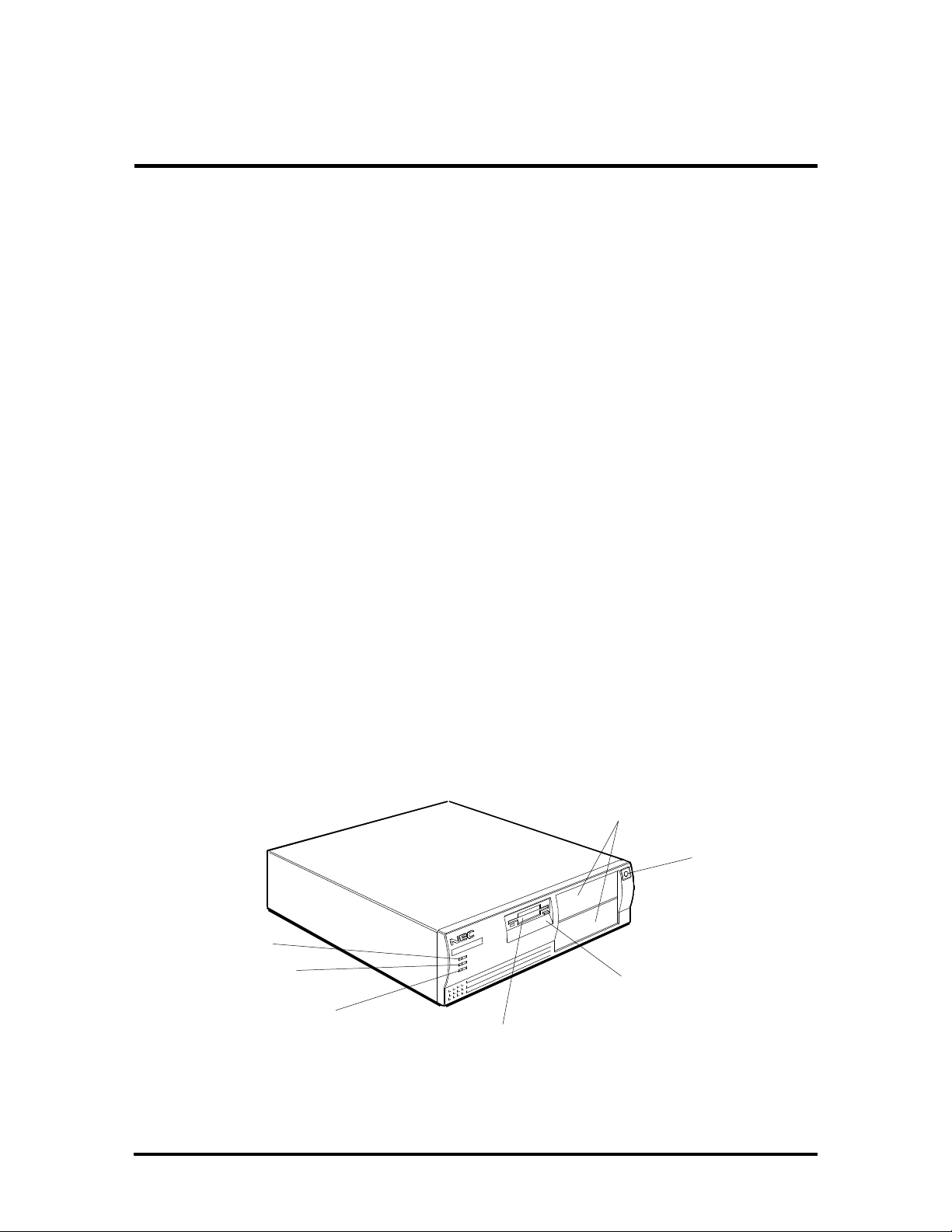
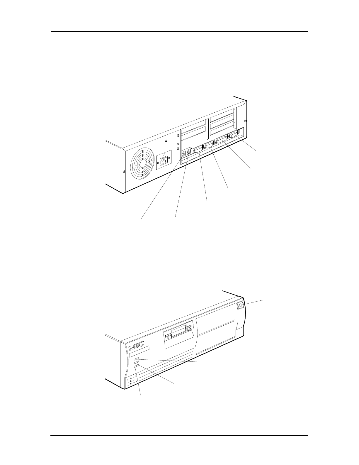
DESKTOP SYSTEM UNIT
The desktop chassis provides an enclosure for the system board, power supply, four storage
device slots, and a four-expansion-slot ISA/Peripheral Component Interconnect (PCI)-bus
backboard. The storage device slots accommodate a 3 1/2-inch diskette drive, a 3 1/2-inch
hard disk (1-inch height), and two 5 1/4-inch storage devices (1.6-inch height). The system
ships with a 3 1/2-inch diskette drive and in some configurations, a hard disk drive leaving
two 5 1/4-inch storage device slots available for optional devices. All desktop models share
the system unit features shown in Figure Section 1-1.
5 1/4-Inch Accessible
Slots (available)
Power Button
Power Lamp
Hard Disk Drive
Busy Lamp
Reset Button
3 1/2-Inch Accessible
Slot (contains 1.44-MB
diskette drive)
Figure Section 1-1 PowerMate Desktop System Unit Features
3 1/2-Inch Internal
Hard Disk Drive Slot
1-2 Technical Information
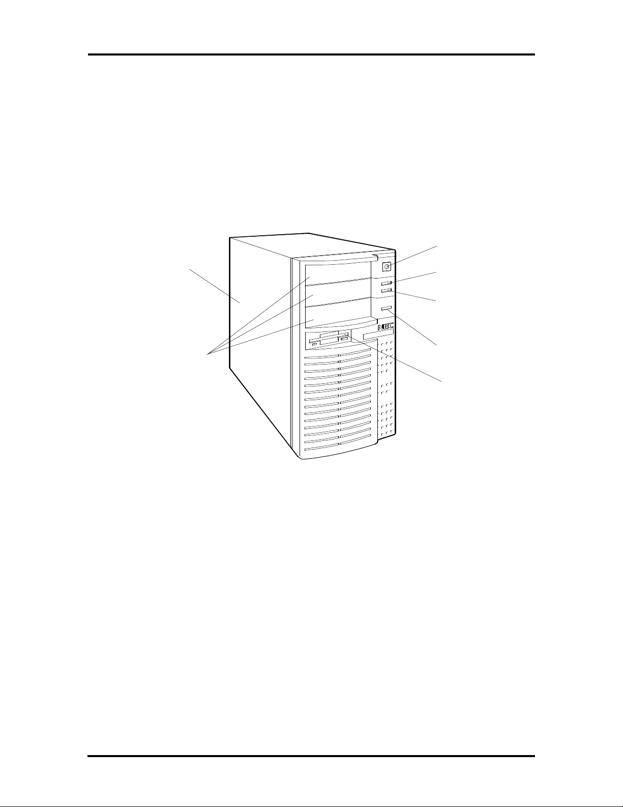
MINITOWER SYSTEM UNIT
The minitower chassis provides an enclosure for the system board, power supply, five
storage device slots, and five-expansion-slot ISA/PCI-bus backboard. The storage device
slots accommodate a 3 1/2-inch diskette drive, two 3 1/2-inch hard disk drives (1-inch
height), and three 5 1/4-inch storage devices (1.6-inch height). The system ships with a
3 1/2-inch diskette and in some configurations, a hard disk drive leaving three 5 1/4-inch
storage device slots available for optional devices.
All minitower models share the system unit features shown in Figure Section 1-2.
Two 3 1/2-Inch
Internal Hard
Disk Drive Slots
5 1/4-Inch
Accessible slots
Figure Section 1-2 PowerMate Minitower System Unit Features
System Board
Power Button
Power Lamp
Hard Disk
Drive Busy
Lamp
Reset Button
3 1/2-Inch
Accessible slot
(contains diskette
drive)
The system boards are the same for bothe computers and contains a Flash ROM which is
upgradeable through the BIOS Update utility (see Section 2).
Key features of the system board are listed below.
n Pentium™ 60-MHz processor
n support for Intel OverDrive™ processor upgrades
n 8 megabytes (MB) of random access memory (RAM)
accepts 36-bit, 70-nano second (ns) single-inline memory modules (SIMMs)
expandable to 80 MB in the desktop and 136 MB in the minitower
n 16-kilobyte (KB) primary cache (8 KB data and 8 KB instructions)

Technical Information 1-3
n 256-KB secondary cache
n Peripheral Component Interconnect (PCI) graphics controller and 32-bit PCI-bus
supports 640 x 480 with 16.8 million colors (24-bit true color), 800 x 600
with 64 K colors 1024 x 768 resolution with 256 colors, and 1280 x 1024
resolution with 16 colors
1-MB (two 256K x 16) video dynamic RAM (DRAM), expandable to 2 MB
n two intelligent drive electronics (IDE) interface connectors
one fast PCI-bus IDE connector (primary interface) used by the hard disk
drive to transfer data at the hard disk's optimum rate
one standard IDE connector (secondary interface) for additional IDE devices
(not used)
n energy saving features: system switches to power save mode when idle for an
established amount of time
n 3 1/2-inch, 1.44-MB diskette drive
n ISA/PCI-bus backboard providing:
in the desktop three ISA expansion slots and one shared ISA/PCI-bus
expansion slot
in the minitower three ISA expansion slots, one PCI-bus expansion slot and
one shared ISA/PCI-bus expansion slot
n external connectors providing an interface for the following external devices:
video graphics array (VGA)-compatible monitor
personal system/2 (PS/2®)-style mouse
PS/2-style keyboard
Enhanced Parallel Port (EPP) and enhanced capabilities port (ECP) are sup-
ported for the parallel printer
two buffered serial ports

1-4 Technical Information
Table Section 1-1 lists the major chips on the system board. See Section 2, Setup and Operation, for a description of the system board's jumpers. See Appendix A, Connector Pin
Assignments, for a list of the system board connectors.
Table Section 1-1 System Board Chips
Chip Description
Pentium 60-MHz processor
28F001 128k x 8 Flash ROM
Intel Mercury PCI/ISA Chip set
82434LX PCI cache and memory controller
82433LX Local bus extension
82378ZB System I/O bridge
Cirrus Logic
Dallas DS12887 Real-time clock
CLDG5434
PCI graphics controller
Intel 82091AA Super I/O controller
Processor
The PowerMate P60 system uses a 64-bit, 60-MHz Pentium microprocessor. The processor
has 16 KB of write-back internal cache, 8 KB for instructions and 8 KB for data. Integrated
into the processor is a math coprocessor.
To use the Pentium processor’s power, the system features an optimized 64-bit memory
interface and complementary 256-KB burst-mode secondary cache.
The special synchronous cache design uses 15-ns static random access memory (SRAM)
that allows data to be sent or received from cache at the fastest possible bursts rate
supported by the Pentium processor.
The Pentium processor is compatible with all 8-, 16-, and 32-bit software written for the
Intel386™, Intel486™, and Pentium processors.
The processor is installed in a 273-pin, zero-insertion-force (ZIF) processor socket. This
socket allows the installation of the next generation of Intel OverDrive processors based on
the Pentium core (PGA type package).

Technical Information 1-5
Secondary Cache
The 16-KB primary cache (8 KB data and 8 KB instruction) is integrated into the
processor. The system board also provides 256 KB of secondary cache, external to the
processor. Cache memory improves read performance by holding copies of code and data
that are frequently requested from the system memory by the processor. Cache memory
is not considered part of the expansion memory.
The cache is connected directly to the processor address bus and uses physical addresses. A
bus feature known as burst enables fast cache fills. Memory areas (pages) can be designated
as cacheable or non-cacheable by software. The cache can also be enabled and disabled
by software.
The write strategy of the cache secondary is write-through. If the write is a cache hit, an
external bus cycle is generated and information is written to the cache. Any area of memory
can be cached in the system. Non-cacheable portions of memory are defined by software.
The cache can be cleared by software instructions.
Flash ROM
Machine language programs are stored in a 28F001 Flash ROM known as the system's
ROM BIOS. The system BIOS and video BIOS are contained in the ROM. The Flash ROM
is 128 KB, which consists of 64 KB of system BIOS, and 32 KB of video BIOS.
The Flash ROM allows the BIOS to be upgraded with the BIOS Update utility without
removing the ROM (see Section 4, Maintenance and Troubleshooting). The BIOS can only
be reprogrammed by powering on the system with the BIOS Update utility diskette in
drive A.
The BIOS programs execute the Power-On Self-Test (POST), update recovery code,
initialize processor controllers, and interact with the display, diskette drives, hard disks,
communication devices, and peripherals. The system BIOS also contains the Setup program
and provides VGA controller support. The hardware setup default copies the ROM BIOS
into RAM (shadowing) for maximum performance.
System BIOS is located in the upper portion of the Flash ROM and video BIOS in the
lower portion. System BIOS is located between F0000h-FFFFFh and supports shadowing
and shadowed memory. System BIOS is write protected and automatically enabled.

1-6 Technical Information
Video BIOS is located between C0000h and C7FFFh. The system memory map in shown in
Table Section 1-3.
Table Section 1-3 System Memory Map
Memory Space Size Function
000000-07FFFF 512 KB Conventional base memory
080000-09FBFF 127 KB Extended conventional base memory
09FC00-09FFFF 1 KB Extended BIOS Data (movable by QEMM and 386 max)
0A0000-0BFFFF 128 KB On-board video memory
0C0000-0C7FFF 32 KB On-board video BIOS
0C8000-0E7FFF 128 KB Available high DOS memory (open to ISA and PCI bus)
0E8000-0ECFFF 20 KB Plug-n-Play ESCD data
0ED000-0EDFFF 4 KB Reserved for logo
0EE000-0EFFFF 8 MB Flash boot block (available for HIMEM)
0F0000-0FFFFF 64 KB System BIOS
100000- On-Board 130 MB Extended and/or Expanded system memory
Flash ROM supports the reprogramming of the system and built-in video BIOS. A jumper
on the system board is provided to prevent unauthorized changes to the BIOS. The factory
default for the jumper is set to enabled, allowing the BIOS to be flashed. See Section 2
Setup and Operation, for jumper information. If the BIOS upgrade is interrupted see Section 4, Maintenance and Troubleshooting, for information on recovering the BIOS in the
event of a catastrophic failure has occurred.
Power Management
Each computer system incorporates power management features that lowers power consumption when there is no activity detected from the keyboard, mouse, diskette drive, or
hard disk drive after a pre-defined period of time. As soon as activity is detected the system
resumes where it left off.
When Power Management is enabled the computer automatically activates power-saving
features and enters a sleep mode whenever inactivity is sensed. The computer's powersaving functions are as follows.
n Reduces the CPU clock speed
The CPU, cache, and video clock speeds are reduced, putting the computer in
sleep mode.

Technical Information 1-7
n Blanks out the monitor
Puts the video controller into sleep mode. The vertical sync clock and blank
signals to the monitor are disabled.
n Forces the IDE devices into stand-by mode
A suspend command is sent to the IDE devices which put the devices into a
stand-by mode.
I/O Addressing
The processor communicates with I/O devices by I/O mapping. The hexadecimal (hex)
addresses of I/O devices are listed in Table Section 1-5.
Table Section 1-5 I/O Address Map
Address (Hex) I/O Device Name
0000-000F DMA controller 1 (channel 0-3)
0020-0021 Interrupt controller 1
0040-0043 Timer 1
0048-004B Timer 2
0060 Keyboard controller byte
0061 NMI, speaker controller byte
0064 Keyboard controller, CMD/STAT byte
0070, bit 7 Enable NMI
0070, bit 6:0 Real-time clock address
0071 Real-time clock data
0073 Reserved for system board Configuration
0075 Reserved for system board Configuration (read only)
0078 BIOS timer
0080-008F DMA page register
00A0-00A1 Interrupt controller 2
00C0-00DE DMA controller 2 (channel 4-7)
00F0 Reset numeric error
0170-0177 Secondary IDE channel
01F0-01F7 Primary IDE channel
0278-027B Parallel port 2
02F8-02FF Asynchronous communications port 2

1-8 Technical Information
Table Section 1-5 I/O Address Map
Address (Hex) I/O Device Name
0376 Secondary IDE channel command port
0377 Secondary IDE channel status port
0378-037F Parallel port 1
03BC-03BF Parallel port 2
03C0-03CF Video Graphics Array (VGA) compare registers
03E8-03EF Serial port 3
03F0-03F5 Diskette channel 1
03F6 Primary IDE channel command port
03F7 (write) Diskette channel command port
03F7, bit 7 Diskette change channel 1
03F7, bits 6:0 Primary IDE channel status port
03F8-03FF Asynchronous communications port 1
0CF8 PCI Configuration Space Enable
0CF9 Deturbo Mode Enable
C000-C0FF 82434LX configuration registers
C200-C2FF 82378IB configuration registers
C300-C3FF Cirrus Video configuration registers
System Memory
The system comes standard with 8-MB of memory. System memory can be expanded up to
80 MB for the desktop system and up 136 MB for the minitower system. Memory expansion is performed using single in-line memory modules (SIMMs) installed in SIMM sockets.
The standard 8 MB of memory is soldered on the system board. The first megabyte includes
the standard 640 KB of base memory. The remaining memory is extended memory. Four
SIMM sockets are integrated on the system board.
The SIMM memory sockets accept 1-, 2-, 4-, 8-, 16-, or 32-MB SIMM sticks. High-speed
RAM is 32 bits wide with four parity bits. SIMMs are 256 K x 36 bit (1 MB), 512 K x 36
bit (2 MB), 1 M x 36 bit (4 MB), 4 M x 36 bit (16 MB), and 8 M x 36 bit (32 MB). There
are no switches or jumpers to set when SIMMs are added.

Technical Information 1-9
The system board's four SIMM sockets are assigned as banks A and B. Each SIMM kit
is inserted into a pair of sockets or bank. Bank A consist of sockets J28 and J27, and in
the desktop version can only accommodate low profile (1-, 2-, and 4-MB) SIMM sticks.
Bank B consist of sockets J25 and J26. Different size SIMMs cannot be intermixed
within a bank. See Section 3, Options, for installation instructions and SIMM memory configurations.
Interrupt Controller
The interrupt controller operates as an interrupt manager for the entire AT system environment. The controller accepts requests from peripherals, issues interrupt requests to the
processor, resolves interrupt priorities, and provides vectors for the processor to determine
which interrupt routine to execute. The interrupt controller has priority assignment modes
that can be reconfigured at any time during system operations.
The interrupt levels are listed in Table Section 1-7. Interrupt-level assignments 0 through 15
are in order of decreasing priority. See Section 2, Setup and Configuration, for information
on changing the interrupts using Setup.
Table Section 1-7 Interrupt Level Assignments
Interrupt Priority Interrupt Device
IRQ00 Counter/Timer
IRQ01 Keyboard
IRQ02 Cascade (INT output from slave)
IRQ03 COM2*
IRQ04 COM1*
IRQ05 Parallel Port 2
IRQ06 Diskette Drive Controller*
IRQ07 Parallel Port 1*
IRQ08 Real-time clock
IRQ09 Available
IRQ10 Available
IRQ11 Available
IRQ12 PS/2 mouse*
IRQ13 Coprocessor
IRQ14 Primary IDE (fast)
IRQ15 Secondary IDE (standard)
*Industry standard locations

1-10 Technical Information
Video Controller
The Cirrus Logic CLDG5434 PCI graphics controller combines powerful elements aimed at
addressing the requirements of personal computer designs. State of the art techniques have
been added for optimizing performance in computer graphic intensive applications and
graphical user interfaces (GUI). A variety of industry standard 32-bit PCI-bus interfaces are
integrated on chip. The key is that PCI-bus interfaces are 32-bit wide.
Included in the video controller are cost saving features such as an integrated palette DAC
and clock synthesizer along with integrated support for multiple bus interfaces and flexible
DRAM-based display memory configurations.
The TrueColor RAMDAC provides 24-bit true color. The integrated dual clock synthesizer
allows full programmability of MCLK (memory clock) and PCLK (pixel clock). The integrated clock synthesizer supports frequencies from 390 kHz to 120 MHz. The CLDG5434
supports up to 2 MB of display memory. The video memory is 256K x 16 DRAM.
The VESA display power management signaling (DPMS) standard is supported, enabling
stand-by, suspend, and off power saving modes. This includes the ability to independently
stop HSYNC of VSYNC and hold them at a static level. Additionally the RAMDAC may
be powered-down and the clock frequencies lowered for further power savings. Color Key
and video overlay are supported.
Video Memory
The 1 MB of on-board video DRAM is expandable to 2 MB and provides graphic resolutions of or 640 x 480 with 16.8 million colors, 800 x 600 with 64K colors, 1024 x 768 with
256 colors, or 1280 x 1024 with 16 colors. Table Section 1-9 provides the possible resolutions with the installed video memory.
Table Section 1-9 Video Resolutions and Frequencies
Resolution
640 x 480 1 MB 256 60 31.5
640 x 480 1 MB 256 72 37.0
640 x 480 1 MB 256 72 44.6
640 x 480 1 MB 65K 60 31.5
640 x 480 1 MB 65K 72 37.0
640 x 480 1 MB 65K 72 44.6
640 x 480 1 MB 16.7M 60 31.5
640 x 480 1 MB 16.7M 72 37.0
Memory
Required
Color
Video Clock (Hz) Horiz Sync (KHz)
640 x 480 1 MB 16.7M 72 44.6
800 x 600 1 MB 256 95(i) 33.8

Technical Information 1-11
Table Section 1-9 Video Resolutions and Frequencies
Resolution
800 x 600 1 MB 256 56 35.2
800 x 600 1 MB 256 60 37.9
800 x 600 1 MB 256 70 44.5
800 x 600 1 MB 256 72 48.0
800 x 600 1 MB 256 76 52.4
800 x 600 1 MB 65K 95(i) 33.8
800 x 600 1 MB 65K 56 35.2
800 x 600 1 MB 65K 70 44.5
800 x 600 1 MB 65K 72 48.0
800 x 600 2 MB 65K 76 52.4
800 x 600 2 MB 16.7M 95(i) 33.8
800 x 600 2 MB 16.7M 56 35.2
800 x 600 2 MB 16.7M 60 37.9
800 x 600 2 MB 16.7M 70 44.5
Memory
Required
Color
Video Clock (Hz) Horiz Sync (KHz)
800 x 600 2 MB 16.7M 72 48.0
1024 x 768 1 MB 256 87(i) 35.5
1024 x 768 1 MB 256 60 48.4
1024 x 768 1 MB 256 66 53.9
1024 x 768 1 MB 256 70 56.1
1024 x 768 1 MB 256 72 57.9
1024 x 768 1 MB 256 76 61.4
1024 x 768 2 MB 65K 87(i) 35.5
1024 x 768 2 MB 65K 60 48.4
1024 x 768 2 MB 65K 66 53.9
1024 x 768 2 MB 65K 70 56.1
1024 x 768 2 MB 65K 72 57.9
1024 x 768 2 MB 65K 76 61.4
1280 x 1024 1 MB 16 87(i) 50
1280 x 1024 1 MB 16 95(i) 50
1280 x 1024 2 MB 256 87(i) 50
1280 x 1024 2 MB 256 95(i) 50

1-12 Technical Information
Table Section 1-9 Video Resolutions and Frequencies
Resolution
1280 x 1024 2 MB 256 60 64.0
1280 x 1024 2 MB 256 70 74.6
1280 x 1024 2 MB 256 74 81.1
(I) Interlaced.
Memory
Required
Color
Video Clock (Hz) Horiz Sync (KHz)
ISA/PCI-Bus Backboard
The ISA/Peripheral Component Interconnect (PCI)-bus backboard provides ISA and PCIbus expansion slots. The backboard is plugged into a bus connectors on the system board.
The desktop computer provides three ISA and one shared ISA/PCI-bus slot. The minitower
computer provides three ISA, one shared ISA/PCI-bus slot, and PCI-bus slot.
ISA Bus
The system board uses the ISA bus for transferring data between the processor and I/O
peripherals and expansion boards. The ISA bus supports 16-bit data transfers and typically
operates at 8 MHz. ISA expansion slot connector pin assignments are provided in
Appendix A.
PCI Local Bus
The industry-standard PCI-bus is a highly-integrated I/O interface that offers the highest
performance local bus available for the Pentium processor. The PCI-bus supports burst
modes that send large chunks of data across the bus, allowing fast displays of highresolution images.
The high-bandwidth PCI-bus eliminates the data bottleneck found in traditional systems,
maintains maximum performance at high clock speeds, and provides a clear upgrade path to
future technologies. PCI expansion slot connector pin assignments are provided in
Appendix A.
PCI Auto Configuration
The system comes with a PCI auto configuration utility that operates in conjunction with
the system’s Setup utility. The utilities automatically configure interrupts, DMA channels,
I/O space, and other parameters to allow addition of PCI boards with minimal intervention.

Technical Information 1-13
Parallel Interface
The system has a 25-pin parallel port on the system board. Specifications for this port
conform to the IBM-PC standards.
The BIOS has automatic ISA printer port sensing. If the BIOS detects an ISA printer
port mapped to the same address, the built-in printer port is disabled. The BIOS also sets
the first parallel interface port it finds as LPT1 and the second port it finds as LPT2. The
interrupt is selected to either IRQ5 or IRQ7 via the Setup.
Interrupt levels for the parallel port are given in Table Section 1-11. Software selectable
base addresses are 3BCh, 378h, and 278h.
Parallel interface signals are output through the system board's 25-pin, D-subconnector. The
connector is located at the rear of the system unit. Pin locations for the parallel interface
connector are shown in Appendix A.
NOTE: Any interrupts used for the built-in par-
allel port is not available for ISA parallel ports.
Table Section 1-11 Parallel Port Addressing and Interrupts
Starting I/O Address Interrupt Level Port
378 IRQ05 LPT1
278 IRQ05 LPT1 or LPT2
3BC IRQ05 LPT1 or LPT2
378* IRQ07 LPT1
278 IRQ07 LPT1 or LPT2
3BC IRQ07 LPT1 or LPT2
*Default for parallel port
1-14 Technical Information
Serial Interface
The system has two standard serial ports (COM1 and COM2). The serial ports support the
standard RS-232C interface (16550 compatible). I/O addresses and interrupt levels for the
two channels are given in Table Section 1-13. The interrupt is selectable via Setup to either
IRQ3 or IRQ4. Software selectable base addresses are 3F8h, 2F8h, 3E8h, and 2E8h. Serial
interface signals are output through the system board's 9-pin, D-subconnector. The connectors are located at the rear of the system unit. Pin locations for the serial interface connector are shown in Appendix A
NOTE: Any interrupts used for the built-in serial
ports are not available for ISA parallel ports.
Table Section 1-13 Serial Port Addressing and Interrupts
Starting I/O Address Interrupt Level Port
3F8* IRQ04 COM1
2F8 IRQ03 COM2
3E8 IRQ04 COM3
2E8 IRQ03 COM4
*Default for serial port
Serial interface specifications include:
n Baud rate up to 19.2 KB per second
n Word length - 5, 6, 7, or 8 bits
n Stop bit - 1, 1.5, or 2 bits
n Start bit - 1 bit
n Parity bit - 1 bit (odd parity or even parity).
Indicator Panel
The indicator panel is attached to the front panel and contains the power lamp, hard disk
drive busy lamp, and reset button. The indicator panel attaches to the system board using
connector J31 (reset connector), J32 (power lamp connector), and J33 (hard disk drive busy
lamp connector).

Technical Information 1-15
POWER SUPPLY
The power supply is mounted inside the system unit. It supplies power to the system board,
option boards, diskette drives, hard disks, keyboard, and mouse. Two connectors connect
the power supply to the system board connector J12. A fan inside the power supply
provides proper ventilation for the system. The power supply in the desktop supplies 145W
of power. The minitower power supply provides 200W. Power requirements and
specifications for both power supplies are provided in Appendix B.
DISKETTE DRIVE
Up to two diskette drives are supported in the system. The drives are connected by a single
ribbon cable with two drive connectors. The system refers to the diskette drives as A and B.
Drive A is for the first drive, B is for a second optional diskette drive. The diskette drive
cable plugs directly into the system board. Typically both diskette drive are terminated. See
Section 3, Options, for installing an optional 5 1/4-inch diskette drive.
Specifications for the diskette drives are provided in Appendix B, Specifications.
HARD DISK DRIVE
The system provides IDE interface connectors on the system board. The system board
supports up to two IDE devices on the standard connector and two IDE devices on the
PCI-bus IDE connector. The system unit provides one storage slot for a 3 1/2-inch
hard disk (1-inch height), and one available storage slots for a optional 5 1/4-inch device
(1.6-inch height). See Section 3, Options, for installing an optional hard disk drive.
Specifications for the diskette drives are provided in Appendix B, Specifications.
KEYBOARD
The PS/2-style keyboard is standard equipment for the system. The keyboard provides a
numeric keypad, separate cursor control keys, and 12 function keys, capable of up to 48
functions. Status lamps on the keyboard indicate: Num (Numeric) Lock, Caps (Capital)
Lock, and Scroll Lock key status. The keyboard's six-pin connector is plugged into the rear
of the base unit. The PS/2-style keyboard connector pin assignments are given in Appendix A, Connector Pin Assignments.

Section 2
Setup and Operation
This section provides information on hardware setup for PowerMate Series computers.
Setup includes unpacking, cabling, and powering up the system. It also includes configuring
the system with the system setup programs. Section 3 provides information for installing
options.
UNPACKING AND REPACKING
Find an area away from devices that generate magnetic fields (electric motors, transformers,
etc.). Place the carton on a sturdy surface, and carefully unpack the system. The carton
contents include the system unit, keyboard, mouse, power cord, user documentation, and
system recovery diskette.
Repack the system using the original shipping carton and packing material. Part numbers for
replacement shipping cartons and packing material are available at the end of Sections 5
and 6.
SETUP
Connect the system components according to the following two subsections.
n Desktop Configuration – for setting up desktop system units.
n Minitower Configuration – for setting up minitower system units.
2-2 Setup and Operation
Desktop Setup
Set up the desktop systems by making the following connections. (See the following subsection, Minitower Setup, if setting up a minitower computer).
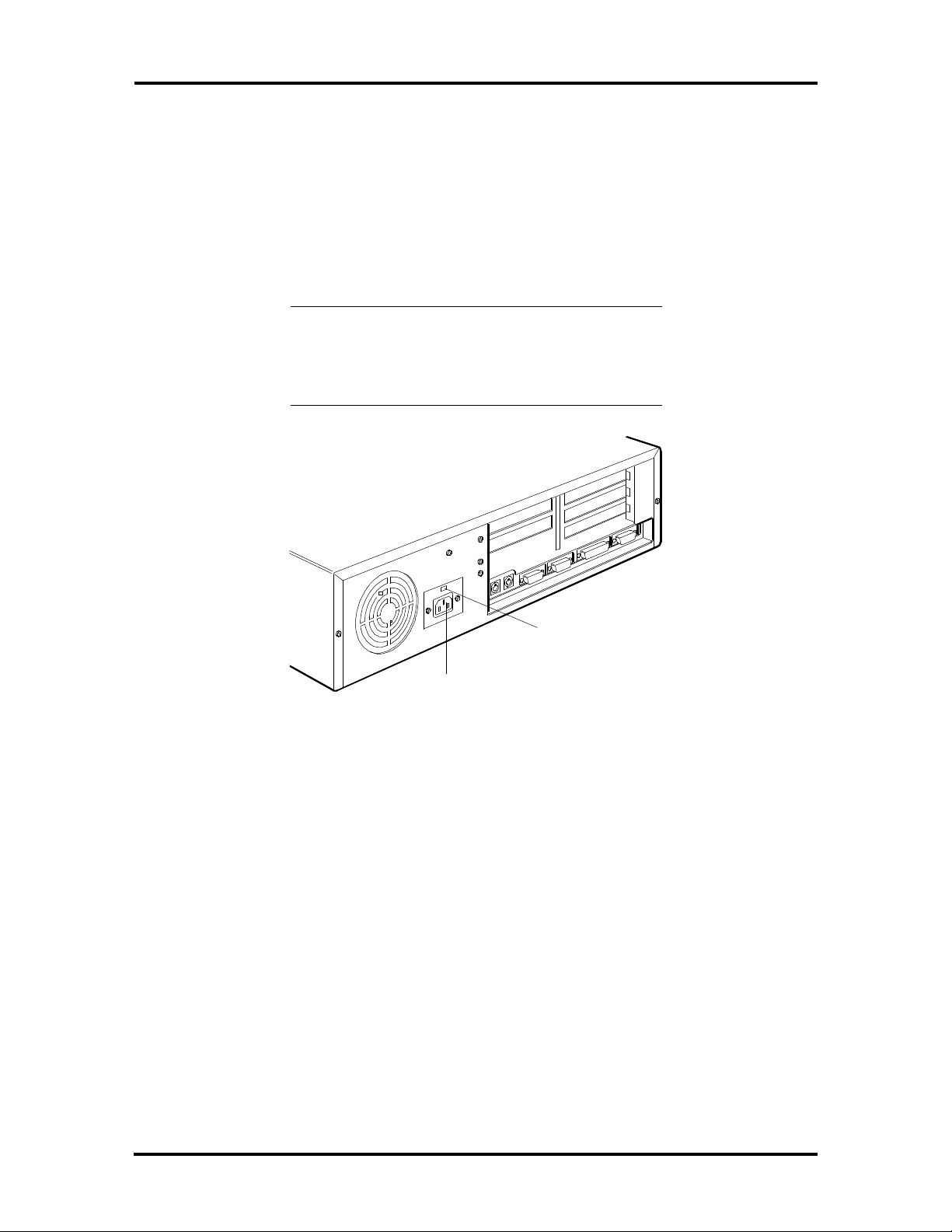
1. At the rear of the system, set the voltage selector switch to 115V or 230V and
insert the power cord into the system power socket (see Figure Section 2-1).
CAUTION: The correct AC input voltage must
be properly set. Select the appropriate voltage
with the voltage selector switch located at the
rear of the system.
Voltage Selector
Switch
System Power
Socket
Figure Section 2-1 Desktop Voltage Selector Switch
Setup and Operation 2-3
2. Connect the keyboard and mouse cables to the back of the system unit (see
Figure 2-2).
3. Connect the, monitor and any other peripherals to the rear panel (see Figure Sec-
tion 2-2). Detailed monitor connections a given in Sections 3, Options.
15-Pin VGA
Monitor
Connector
Parallel
Printer Port
Serial
Port 2
Serial
Port 1
Keyboard
Port
Figure Section 2-2 Desktop Peripheral Connections
Mouse
Port
4. Press the power button to power-on the system (see Figure Section 2-4). The user
lamps and reset button are also identified in the figure.
Power
Lamp
Hard Disk Drive
Busy Lamp
Reset
Figure Section 2-4 Desktop Lamps, Reset Button, and Power Button
Button
Power
Button
 Loading...