


PROPRIETARY NOTICE AND LIABILITY DISCLAIMER
The information disclosed in this document, including all designs and related materials, is
the valuable property of NEC Computer Systems Division, Packard Bell NEC, Inc.
(hereinafter “NECCSD, PB NEC”) and/or its licensors. NECCSD and/or its licensors, as
appropriate, reserve all patent, copyright and other proprietary rights to this document, including all design, manufacturing, reproduction, use, and sales rights thereto, except to the
extent said rights are expressly granted to others.
The NECCSD product(s) discussed in this document are warranted in accordance with the
terms of the Warranty Statement accompanying each product. However, actual
performance of each such product is dependent upon factors such as system configuration,
customer data, and operator control. Since implementation by customers of each product
may vary, the suitability of specific product configurations and applications must be
determined by the customer and is not warranted by NECCSD.
To allow for design and specification improvements, the information in this document is
subject to change at any time, without notice. Reproduction of this document or portions
thereof without prior written approval of NECCSD is prohibited.
NEC is a registered trademark of NEC Corporation. FastFacts, MultiSync, and PowerMate are either trademarks or registered trademarks of
NEC Technologies, Inc.; all these trademarks are used under license by Packard Bell NEC, Inc.
All other product, brand, or trade names used in this publication are the trademarks or registered trademarks of their respective trademark
owners.
First Printing — February 1997
Copyright 1997
NEC Computer Systems Division
Packard Bell NEC, Inc.
1414 Massachusetts Avenue
Boxborough, MA 01719-2298
All Rights Reserved

xiii
Preface
This service and reference manual for NEC PowerMate Office 2513/2516 Series
computers contains hardware and interface information for users who need an overview of
system design. The manual also includes system setup information, procedures for installing
options, and illustrated parts lists. The manual is written for NECCSD-trained customer
engineers, system analysts, service center personnel, and dealers.
The manual is organized as follows:
Section 1 — Technical Information, provides an overview of the minitower computer
features, hardware design, interface ports, and internal devices. System specifications are
listed including dimensions, weight, environment, safety compliance, power consumption,
and memory.
Section 2 — Setup and Operation, includes unpacking, setup, and operation information.
Also included are procedures for configuring the system through the Setup utility program,
setting passwords and power management features, and using the BIOS Update utility.
Section 3 — Option Installation, provides installation procedures for adding optional
expansion boards, diskette and hard disk storage devices, system and video memory, and
processor updates.
Section 4 — Maintenance and Troubleshooting, includes recommended maintenance
information, provides possible computer problems and their solutions, and provides battery
replacement procedures. Also included are NECCSD telephone numbers for obtaining
service, accessing the NECCSD Bulletin Board Service, and accessing the FastFacts™
service.
Section 5 — Repair, includes computer disassembly and reassembly procedures. Also
includes an exploded view diagram of the multimedia computer and a parts lists for fieldreplaceable parts.
Appendix A — Connector Pin Assignments, provides a list of system boards’ internal
connector pin assignments and a list of external pin assignments for the keyboard, mouse,
serial ports, parallel port, and video port.
Appendix B — Hard Disk Drive Specifications and Jumper Settings, provides
specifications and jumper settings for the hard disk drives shipped with the computers.
Appendix C — System Board Jumpers, includes information on setting jumpers for
processor upgrades, and clearing a password.
Appendix D — CD-ROM Reader Specifications and Jumper Settings, gives
specifications and jumper settings for the CD-ROM reader shipped with the computers.
Appendix E — Zip Drive Specifications and Jumper Settings, gives specifications and
jumper settings for the Zip drive shipped with certain computer models.

Abbreviations
xv
A ampere
AC alternating current
AT advanced technology (IBM PC)
BBS Bulletin Board Service
BCD binary-coded decimal
BCU BIOS Customized Utility
BIOS basic input/output system
bit binary digit
BUU BIOS Upgrade Utility
bpi bits per inch
bps bits per second
C capacitance
C centigrade
Cache high-speed buffer storage
CAM constantly addressable memory
CAS column address strobe
CD/ROM compact disk-ROM
CG character generator
CGA Color Graphics Adapter
CGB Color Graphics Board
CH channel
clk clock
cm centimeter
CMOS complementary metal oxide
semiconductor
COM communication
CONT contrast
CPGA ceramic pin grid array
CPU central processing unit
DAC digital-to-analog converter
DACK DMA acknowledge
DC direct current
DIP dual in-line package
DLAB Divisor Latch Address bit
DMA direct memory access
DMAC DMA controller
DOS disk operating system
DRAM dynamic RAM
ECC error checking and correction
EDO extended data output
EGA Enhanced Graphics Adapter
EPROM erasable and programmable ROM
EVGA Enhanced Video Graphics Array
F Fahrenheit
FAX facsimile transmission
FCC Federal Communications Commission
FG frame ground
FM frequency modulation
FP fast page
FRU field-replaceable unit
GB gigabyte
GND ground
HEX hexadecimal
HGA Hercules Graphics Adapter
Hz hertz
IC integrated circuit
ID identification
IDE intelligent device electronics
IDTR interrupt descriptor table register
in. inch
INTA interrupt acknowledge
IPB illustrated parts breakdown
IR infrared
IRR Interrupt Request register
ISA Industry Standard Architecture
ISR In Service register
I/O input/output
IPC integrated peripheral controller
ips inches per second
IRQ interrupt request
K kilo (1024)
k kilo (1000)
KB kilobyte
kg kilogram

xvi Abbreviations
kHz kilohertz
lb pound
LED light-emitting diode
LSB least-significant bit
LSI large-scale integration
M mega
mA milliamps
max maximum
MB megabyte
MDA Monochrome Display Adapter
MFM modified frequency modulation
MHz megahertz
mm millimeter
ms millisecond
MSB most-significant bit
NASC National Authorized Service Center
NC not connected
NMI Non-maskable Interrupt
ns nanosecond
NSRC National Service Response Center
PAL programmable array logic
PC personal computer
PCB printed circuit board
PCI Peripheral Component Interconnect
PDA personal digital assistant
PFP plastic flat package
PIO parallel input/output
pixel picture element
PLCC plastic leaded chip carrier
PLL phase lock loop
p-p peak-to-peak
PPI programmable peripheral interface
PROM programmable ROM
QFP quad flat pack
RAM random-access memory
RAMDAC RAM digital-to-analog converter
RAS row address strobe
RGB red green blue
RGBI red green blue intensity
ROM read-only memory
rpm revolutions per minute
R read
RTC real-time clock
R/W read/write
S slave
SCSI Small Computer System Interface
SG signal ground
SIMM single inline memory module
SPM standard page mode
SRS Sound Retrieval System
SVGA Super Video Graphics Array
SW switch
TAC Technical Assistance Center
TSC Technical Support Center
TTL transistor/transistor logic
tpi tracks per inch
USB universal serial bus
V volt
Vac volts, alternating current
Vdc volts, direct current
VESA video electronics standards
association
VFC VESA-compliant feature connector
VGA Video Graphics Array
VRAM video RAM
W watt
W write

Contents
Page
Preface......................................................................................................................... xiii
Abbreviations............................................................................................................... xv
Section 1 Technical Information
System Overview......................................................................................................... 1-1
System Chassis ............................................................................................................ 1-6
System Board .............................................................................................................. 1-7
Processor.............................................................................................................. 1-10
Secondary Cache .................................................................................................. 1-10
System and Video BIOS ....................................................................................... 1-11
iii
Power Management .............................................................................................. 1-12
I/O Addressing...................................................................................................... 1-12
System Memory.................................................................................................... 1-14
Interrupt Controller............................................................................................... 1-15
Integrated Graphics............................................................................................... 1-16
Motion Video Controller................................................................................ 1-16
Graphics Accelerator...................................................................................... 1-17
Video Memory............................................................................................... 1-17
AMI Multimedia Channel (AMC/VFC) Connector................................................ 1-18
Standard VFC Mode...................................................................................... 1-18
DVS Mode .................................................................................................... 1-18
MDP/MPP Mode........................................................................................... 1-19
ISA Bus................................................................................................................ 1-19
PCI Local Bus ...................................................................................................... 1-19
PCI Auto Configuration........................................................................................ 1-19
PCI/IDE Ports ...................................................................................................... 1-20
Parallel Interface................................................................................................... 1-20
Serial Interface...................................................................................................... 1-21
Universal Serial Bus (USB) Interface .................................................................... 1-22
Power Supply .............................................................................................................. 1-22
Diskette Drive.............................................................................................................. 1-22
Hard Disk Drive........................................................................................................... 1-22
Zip Drive ..................................................................................................................... 1-22

iv Contents
Keyboard..................................................................................................................... 1-23
Mouse ......................................................................................................................... 1-23
Uninterruptible Power Supply (UPS) ........................................................................... 1-23
Multimedia Components.............................................................................................. 1-23
Integrated Audio................................................................................................... 1-24
CD-ROM Reader.................................................................................................. 1-24
Speakers............................................................................................................... 1-24
Microphone .......................................................................................................... 1-25
Fax/Data/Speakerphone Modem Board........................................................................ 1-25
Plug and Play............................................................................................................... 1-25
Power Management..................................................................................................... 1-25
Specifications............................................................................................................... 1-26
Section 2 Setup and Operation
Unpacking and Repacking............................................................................................ 2-1
Setup........................................................................................................................... 2-2
Using System Controls................................................................................................. 2-8
Power Button ....................................................................................................... 2-8
Suspend Button .................................................................................................... 2-9
Reset Button......................................................................................................... 2-9
CD-ROM Reader......................................................................................................... 2-9
Zip Drive ..................................................................................................................... 2-11
CD Restore.................................................................................................................. 2-12
Selecting CD Restore Options............................................................................... 2-12
Restoring Individual Files...................................................................................... 2-13
Selecting Files................................................................................................ 2-13
Checking Selected Files.................................................................................. 2-14
Restoring the Files ......................................................................................... 2-14
Recovering the System.......................................................................................... 2-14
Checking Installed Memory Configuration ................................................................... 2-16
System Configuration................................................................................................... 2-16
Setup Utility.......................................................................................................... 2-17
How to Start Setup............................................................................................... 2-18
How to Use Setup................................................................................................. 2-19
Menu Bar....................................................................................................... 2-19
Legend Bar.................................................................................................... 2-20
Field Help Window ........................................................................................ 2-21

Contents v
General Help Window.................................................................................... 2-21
Main Menu Options ....................................................................................... 2-21
IDE Adapters................................................................................................. 2-22
Memory Cache............................................................................................... 2-24
Memory Shadow............................................................................................ 2-25
Boot Options ................................................................................................. 2-25
Numlock........................................................................................................ 2-26
Advanced Menu.................................................................................................... 2-26
Integrated Peripherals Menu........................................................................... 2-27
Security Menu....................................................................................................... 2-29
Power Menu......................................................................................................... 2-30
Boot Menu ........................................................................................................... 2-31
Exit Menu............................................................................................................. 2-32
Save Changes & Exit ..................................................................................... 2-32
Discard Changes & Exit................................................................................. 2-32
Get Default Values......................................................................................... 2-33
Load Previous Values .................................................................................... 2-33
Save Changes................................................................................................. 2-33
BIOS Update Utility .................................................................................................... 2-33
NECCSD Bulletin Board Service.......................................................................... 2-34
Using the BIOS Update Utility.............................................................................. 2-35
Section 3 Option Installation
General Rules for Installing Options............................................................................. 3-1
Precautions.................................................................................................................. 3-2
Removing the System Unit Cover ................................................................................ 3-3
Expansion Boards........................................................................................................ 3-6
Expansion Slot Locations...................................................................................... 3-6
Expansion Board Installation................................................................................. 3-7
Expansion Board Removal............................................................................. 3-9
SIMM Memory Upgrade ............................................................................................. 3-10
Checking System Memory..................................................................................... 3-10
SIMM Removal.................................................................................................... 3-13
SIMM Installation................................................................................................. 3-14
Video Memory Upgrade .............................................................................................. 3-15
Video Memory Upgrade to 2 MB ......................................................................... 3-15
Video Memory Upgrade to 4 MB ......................................................................... 3-16

vi Contents
Processor Upgrade....................................................................................................... 3-18
Processor Removal ............................................................................................... 3-18
Processor Installation............................................................................................ 3-19
Data Storage Devices................................................................................................... 3-21
Device Slots.......................................................................................................... 3-21
Device Preparation................................................................................................ 3-22
Device Cables....................................................................................................... 3-23
Diskette Drive Signal Cable............................................................................ 3-24
IDE Signal Cables.......................................................................................... 3-24
System Power Cables..................................................................................... 3-25
Device Cabling...................................................................................................... 3-26
Cabling an Additional IDE Device.................................................................. 3-26
Cabling a Additional Diskette Drive ............................................................... 3-27
Storage Device Installation.................................................................................... 3-27
Removing the Front Panel.............................................................................. 3-28
Installing an Additional 5 1/4-Inch Device...................................................... 3-31
Reinstalling the Front Panel............................................................................ 3-33
Installing an Additional 3 1/2-Inch Device...................................................... 3-34
Adding External Options.............................................................................................. 3-36
Parallel Printer ...................................................................................................... 3-36
RS-232C Device Connection................................................................................. 3-37
Section 4 Maintenance and Troubleshooting
Maintenance ................................................................................................................ 4-2
System Cleaning.................................................................................................... 4-2
Keyboard Cleaning................................................................................................ 4-3
Mouse Cleaning.................................................................................................... 4-4
Troubleshooting........................................................................................................... 4-5
Diagnosing and Solving Problems ......................................................................... 4-5
CMOS Battery Replacement................................................................................. 4-11
UPS Battery Replacement..................................................................................... 4-13
Section 5 Repair
Disassembly and Reassembly........................................................................................ 5-1
System Unit Cover Removal ................................................................................. 5-2
Expansion Board Removal.................................................................................... 5-3
Front Panel Assembly Removal............................................................................. 5-4

Contents vii
Blank Panel and Metal Slot Cover Removal .......................................................... 5-5
Speaker Assembly Removal .................................................................................. 5-6
Card Guide and Fan Assembly Removal................................................................ 5-7
System Lamp Cable Assembly Removal................................................................ 5-7
Suspend Switch and Reset Switch Removal .......................................................... 5-8
SIMM Removal.................................................................................................... 5-9
5 1/4-Inch Device Removal................................................................................... 5-10
3 1/2-Inch Hard Disk Drive Removal .................................................................... 5-11
3 1/2-Inch Diskette Drive Removal ....................................................................... 5-12
Power Supply Removal......................................................................................... 5-13
ISA/PCI Backboard Removal................................................................................ 5-14
System Board Removal......................................................................................... 5-15
Illustrated Parts Breakdown.................................................................................. 5-16
Appendix A Connector Pin Assignments
Serial Interface Connectors.......................................................................................... A-4
Parallel Interface Connector......................................................................................... A-5
Vga Interface Connector Pin Assignments.................................................................... A-7
Pc Speaker Connector Pin Assignments ....................................................................... A-8
Power Supply Connector ............................................................................................. A-8
Keyboard and Mouse Connectors................................................................................. A-9
Suspend Button Connector .......................................................................................... A-9
Fan Connector............................................................................................................. A-9
Diskette Drive Interface Pin Assignments.....................................................................A-10
Ide Interface Connectors.............................................................................................. A-11
Simm Sockets..............................................................................................................A-12
ISA/PCI-Bus Backboard Connector Pin Assignments...................................................A-13
ISA Expansion Bus Connector Pin Assignments...........................................................A-15
PCI Expansion Bus Connector Pin Assignments........................................................... A-17
CD Audio-in Connector Pin Assignments.....................................................................A-19
MIDI/Game Port Connector ........................................................................................ A-19
Modem-in Connector Pin Assignments.........................................................................A-20
Power LED Connector Pin Assignments ......................................................................A-20
Hard Disk LED Connector Pin Assignments ................................................................A-20
Microphone in Connector Pin Assignments..................................................................A-21
Reset Connector Pin Assignments................................................................................A-21
Line Out Connector Pin Assignments...........................................................................A-21

viii Contents
Video Memory Card Connectors Pin Assignments .......................................................A-22
Universal Serial Bus Connectors Pin Assignments........................................................A-24
AMI Multimedia Connector.........................................................................................A-25
Appendix B Hard Disk Drive Specifications and Jumper Settings
1.6-GB Hard Disk Drive Specifications and Jumper Settings........................................ B-1
2.5-GB Hard Disk Drive Specifications and Jumper Settings........................................ B-3
Appendix C System Board Jumpers
Jumper Locations......................................................................................................... C-1
Changing Processor Jumper Settings............................................................................ C-2
Changing the Password................................................................................................ C-3
Appendix D CD-ROM Reader Specifications and Jumper Settings
Eight-Speed CD-ROM Reader..................................................................................... D-1
Appendix E Zip Drive Specifications and Jumper Settings
Zip Drive ..................................................................................................................... E-1
Glossary
Index
Figures
1-1 PowerMate Office 2513/2516 Series Components.......................................... 1-1
1-2 PowerMate Office Front View ....................................................................... 1-3
1-3 PowerMate Office Rear View ........................................................................ 1-3
2-1 Voltage Selector Switch................................................................................. 2-2
2-2 Peripheral Connections................................................................................... 2-3
2-3 Eight-Watt Speaker........................................................................................ 2-4
2-4 Connecting the Speakers and Microphone...................................................... 2-5
2-5 The Microphone............................................................................................. 2-5
2-6 Fax/Modem Connections................................................................................ 2-6
2-7 The Uninterruptible Power Supply ................................................................. 2-7

Contents ix
2-8 System Lamps and Control Buttons ............................................................... 2-8
2-9 Basic CD-ROM Reader Controls and Indicators............................................. 2-10
2-10 Zip Drive Controls and Indicators .................................................................. 2-11
2-11 Setup Utility Main Menu Window.................................................................. 2-18
3-1 Removing Cover Screws................................................................................ 3-3
3-2 Removing the Cover ...................................................................................... 3-4
3-3 Aligning the Cover......................................................................................... 3-5
3-4 Locating Expansion Slots............................................................................... 3-6
3-5 Removing a Slot Cover .................................................................................. 3-7
3-6 Inserting the Board ........................................................................................ 3-8
3-7 Removing the Screw ...................................................................................... 3-9
3-8 System Board Upgrade Sockets and Connectors ............................................ 3-11
3-9 SIMM Socket Identification........................................................................... 3-11
3-10 Removing a SIMM......................................................................................... 3-13
3-11 Inserting the SIMM........................................................................................ 3-14
3-12 Aligning the Video Memory Module with the Socket ..................................... 3-16
3-13 Aligning the Video Memory Card with the Socket.......................................... 3-17
3-14 Releasing the Heatsink Clamp ........................................................................ 3-18
3-15 Aligning the Processor with the Socket .......................................................... 3-19
3-16 Replacing the Heatsink................................................................................... 3-20
3-17 Locating the Device Slots............................................................................... 3-22
3-18 System Board Cable Connectors .................................................................... 3-23
3-19 Diskette Drive Signal Cable............................................................................ 3-24
3-20 IDE Signal Cable ........................................................................................... 3-25
3-21 Power Cable Connectors................................................................................ 3-25
3-22 Connecting IDE Device Cables ...................................................................... 3-26
3-23 Connecting 1.2-MB Diskette Drive Cables..................................................... 3-27
3-24 Removing the Front Panel.............................................................................. 3-28
3-25 Locating the Blank Panel Tabs ....................................................................... 3-29
3-26 Locating the Slot Cover ................................................................................. 3-30
3-27 Attaching the Device Rails ............................................................................. 3-31
3-28 Device Screws ............................................................................................... 3-32
3-29 Aligning the Front Panel................................................................................. 3-33
3-30 Locating the 3 1/2-Inch Drive Slot ................................................................. 3-34
3-31 Securing the Hard Disk Drive......................................................................... 3-35
3-32 Connecting a Printer Cable............................................................................. 3-37
3-33 Connecting the RS-232C Cable...................................................................... 3-38
4-1 Removing the Keyboard Enclosure................................................................. 4-3
4-2 Removing the Mouse Ball Cover.................................................................... 4-4
4-3 Locating the Battery....................................................................................... 4-11
4-4 Battery Removal ............................................................................................ 4-12
4-5 Removing the Battery Cover.......................................................................... 4-13

x Contents
4-6 Replacing the Battery..................................................................................... 4-14
4-7 Replacing the Battery Cover........................................................................... 4-15
5-1 Removing the Expansion Board ..................................................................... 5-3
5-2 Front Panel Removal...................................................................................... 5-4
5-3 Blank Panel Removal ..................................................................................... 5-5
5-4 Removing the Metal Slot Cover ..................................................................... 5-5
5-5 Speaker and Card Guide/Fan Assembly Location............................................ 5-6
5-6 SIMM Socket ................................................................................................ 5-9
5-7 Removing the Device Screws......................................................................... 5-10
5-8 Removing the 3 1/2-Inch Hard Disk Drive...................................................... 5-11
5-9 Diskette Drive Screws.................................................................................... 5-12
5-10 Power Supply Screws .................................................................................... 5-13
5-11 ISA/PCI Backboard Screws........................................................................... 5-14
5-12 System Board Screws .................................................................................... 5-15
5-13 PowerMate Office 2513/2516 Computers Illustrated Parts Breakdown.......... 5-19
A-1 System Board Internal Connectors................................................................. A-1
A-2 System Board External Connectors................................................................ A-2
A-3 Serial Interface............................................................................................... A-4
A-4 Parallel Interface Connector........................................................................... A-5
A-5 VGA Interface Connector.............................................................................. A-7
A-6 Power Supply Connector Pin Assignments..................................................... A-8
C-1 System Board Jumper Locations .................................................................... C-1
C-2 Processor Speed Jumper Settings................................................................... C-3
Tables
1-1 System Configurations ................................................................................... 1-4
1-2 Software Shipped with the PowerMate 2513/2516 Series Computers............. 1-5
1-3 System Board Chips....................................................................................... 1-9
1-4 System Memory Map..................................................................................... 1-11
1-5 I/O Address Map ........................................................................................... 1-12
1-6 SIMM Memory Upgrade Path........................................................................ 1-14
1-7 Interrupt Level Assignments........................................................................... 1-16
1-8 Parallel Port Addressing and Interrupts .......................................................... 1-20
1-9 Serial Port Addressing and Interrupts............................................................. 1-21
1-10 Specifications................................................................................................. 1-26

Contents xi
2-1 Setup Key Functions...................................................................................... 2-20
2-2 Main Menu Parameters .................................................................................. 2-22
2-3 IDE Hard Disk Parameters............................................................................. 2-24
2-4 Memory Cache Parameters............................................................................. 2-25
2-5 Boot Parameters ............................................................................................ 2-25
2-6 Numlock Parameters...................................................................................... 2-26
2-7 Advanced Menu Parameters........................................................................... 2-27
2-8 Integrated Peripherals Parameters .................................................................. 2-28
2-9 System Security Options ................................................................................ 2-29
2-10 Power Management Parameters ..................................................................... 2-31
3-1 SIMM Memory Upgrade Path........................................................................ 3-12
4-1 NECCSD Service and Information Telephone Numbers................................. 4-1
4-2 Problems and Solutions.................................................................................. 4-5
5-1 PowerMate Office 2513/2516 Computers Disassembly Sequence................... 5-1
5-2 PowerMate Office 2513/2516 Series Model Numbers .................................... 5-16
5-3 PowerMate Office 2513/2516 Computers FRU List....................................... 5-17
5-4 PowerMate Office 2513/2516 Computers Documentation and Packaging....... 5-18
A-1 System Board Connectors.............................................................................. A-3
A-2 RS-232C Serial Port Connector Pin Assignments ........................................... A-4
A-3 Parallel Printer Port Connector Pin Assignments ............................................ A-6
A-4 VGA Interface Connector Pin Assignments.................................................... A-7
A-5 PC Speaker Connector Pin Assignments......................................................... A-8
A-6 Keyboard and Mouse Connector Pin Assignments.......................................... A-9
A-7 Suspend Connector Pin Assignments.............................................................. A-9
A-8 Fan Connector Pin Assignments..................................................................... A-9
A-9 Diskette Drive Connector Pin Assignments .................................................... A-10
A-10 PCI/IDE Connector Pin Assignments.............................................................A-11
A-11 SIMM Socket Pin Assignments......................................................................A-12
A-12 ISA/PCI-Bus Backboard Connector Pin Assignments..................................... A-13
A-13 ISA Expansion Slot Pin Assignments..............................................................A-15
A-14 PCI Expansion Slot Pin Assignments..............................................................A-17
A-15 CD Audio-In Connector Pin Assignments.......................................................A-19
A-16 MIDI/Game Port Connector Pin Assignments................................................A-19
A-17 Modem-In Connector Pin Assignments .......................................................... A-20

xii Contents
A-18 Power LED Connector Pin Assignments .......................................................A-20
A-19 Hard Disk LED Connector Pin Assignments...................................................A-20
A-20 Microphone In Connector Pin Assignments.................................................... A-21
A-21 Reset Connector Pin Assignments.................................................................. A-21
A-22 Line Out Connector Pin Assignments............................................................A-21
A-23 Video Memory Card Connector J17 Pin Assignments..................................... A-22
A-24 Video Memory Card Connector J25 Pin Assignments..................................... A-23
A-25 Universal Serial Bus Connector Pin Assignments............................................A-24
A-26 AMI Multimedia (Standard VFS Mode) Connector Pin Assignments..............A-25
A-27 AMI Multimedia (DVS Mode) Connector Pin Assignments............................A-26
A-28 AMI Multimedia (MDP Mode) Connector Pin Assignments........................... A-27
A-29 AMI Multimedia (MPP Mode) Connector Pin Assignments............................A-28
B-1 1.6-GB Hard Disk Drive Specifications.......................................................... B-1
B-2 2.5-GB Hard Disk Drive Specifications.......................................................... B-3
D-1 NEC Eight-Speed CD-ROM Specifications.................................................... D-2
E-1 Zip Drive Specifications................................................................................. E-2
Section 1
Technical Information
SYSTEM OVERVIEW
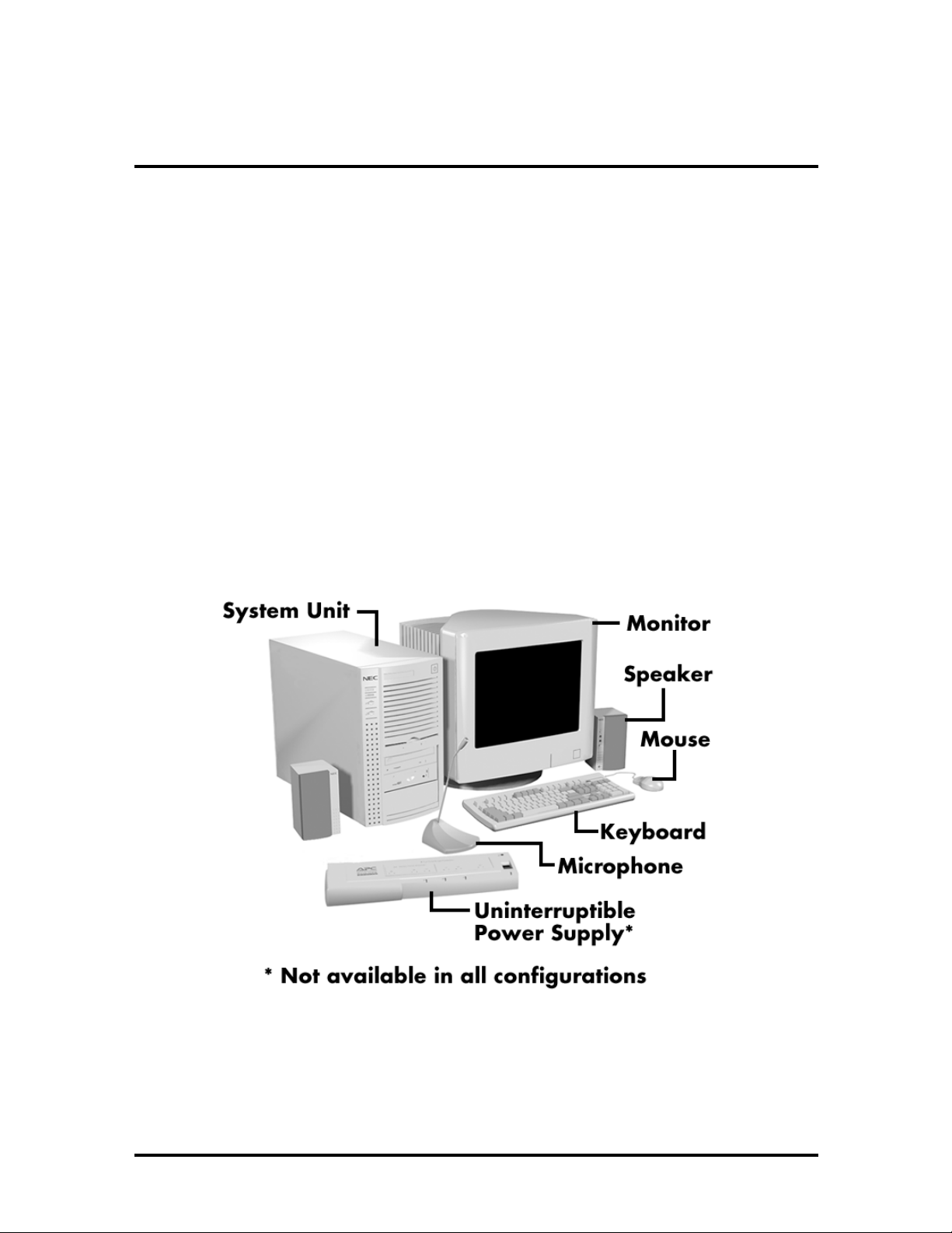
NEC PowerMate Office 2513/2516 Series computers are tailored for small office use.
Each model provides in-demand office technologies and applications including fax, internal
phone, and integrated audio. The Plug and Play I/O controller allows devices to be added
easily, without reconfiguring the system. In addition, PowerMate systems support
processor, memory, and video upgrades in anticipation of future advances in computing and
multimedia.
The information in this section applies both to PowerMate Office 2513 and 2516 models,
except where noted. Figure 1-1 shows the components shipped with some PowerMate
Office 2516 systems.
Figure 1-1 PowerMate Office 2513/2516 Series Components

1-2 Technical Information
The basic hardware features for the PowerMate Office system are listed below:
Intel Pentium 133-MHz processor (2513 models)
Intel Pentium 166-MHz processor (2516 models)
16 MB of EDO RAM (2513 models, some 2516 models), expandable to 128 MB
32 MB of EDO RAM (some 2516 models), expandable to 128 MB
ATI VT2 graphics accelerator integrated on system board
1 MB video DRAM (expandable up to 4 MB)
256 KB pipeline burst cache memory
1.6-GB Hard Disk Drive (2513 models, some 2516 models)
2.5-GB Hard Disk Drive (some 2516 models)
NEC MultiSpin 8X CD-ROM reader
Stereo speakers, 8-watt
OPL3-SA sound system integrated on system board
33.6-Kbps Fax/Data/Voice Modem
Iomega Zip 100 ATA drive (some 2516 models)
Uninterruptible power supply (some 2516 models)
Microphone.
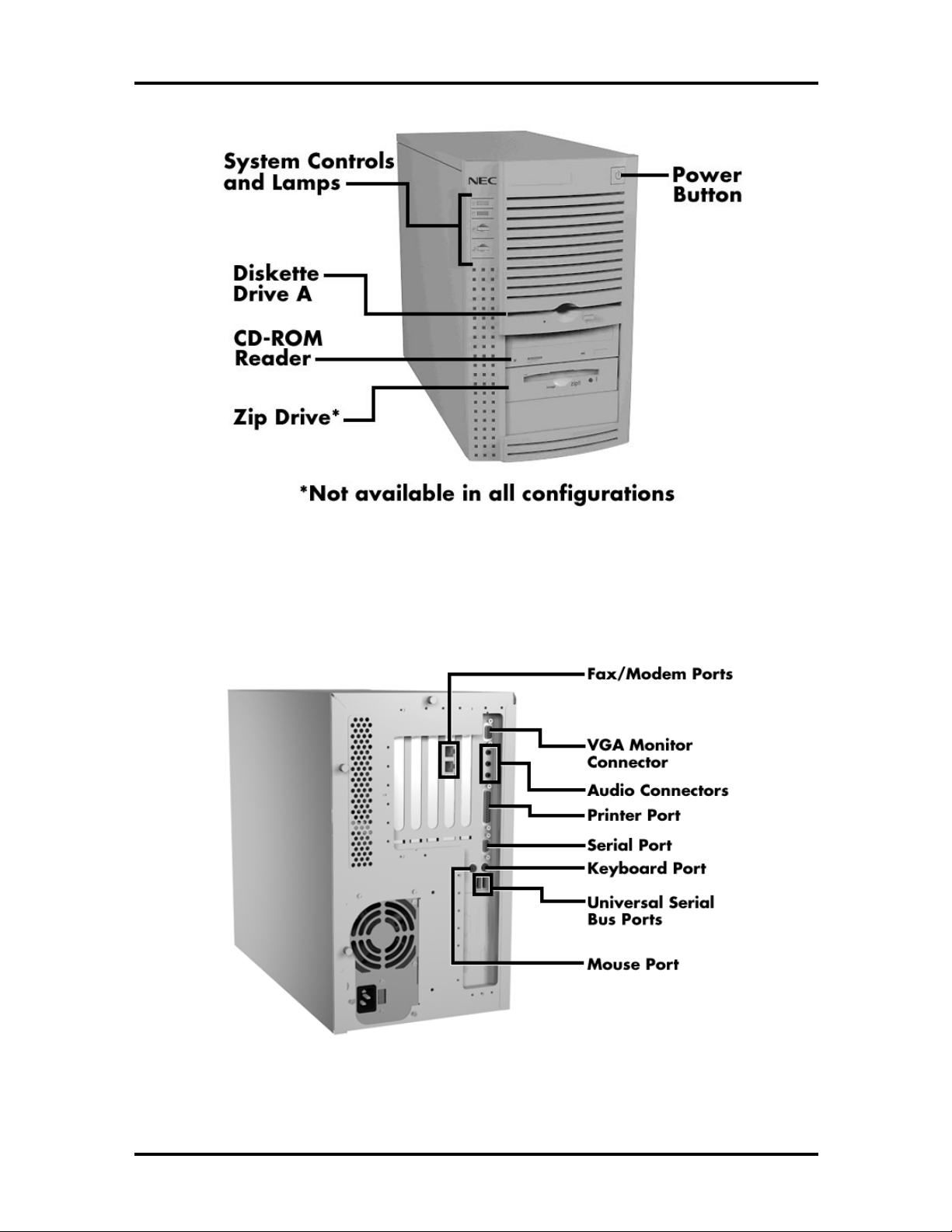
Figure 1-2 identifies the components, lamps, and controls on the front of the system.
Figure 1-3 identifies the connectors on the back of the system.
Technical Information 1-3
Figure 1-2 PowerMate Office Front View
Figure 1-3 PowerMate Office Rear View

1-4 Technical Information
NEC PowerMate 2513/2516 Series computers include the configurations identified in
Table 1-1.
Table 1-1 System Configurations
2513
(MT-2150-24833C)
System Unit
CPU Pentium 133 MHz Pentium 166 MHz Pentium 166 MHz
System RAM* 16 MB EDO 16 MB EDO 32 MB EDO
IDE Hard Disk 1.6 GB Maxtor 1.6 GB Maxtor 2.5 GB WDAC32500
Cache 256 KB
Video DRAM** 1 MB 1 MB 1 MB
Diskette Disk
Drive
CD-ROM Reader NEC 8X ATAPI NEC 8X ATAPI NEC 8X ATAPI
Zip Drive NA NA 100 MB Iomega Zip
Audio Yamaha OPL3-SA Yamaha OPL3-SA Yamaha OPL3-SA
Internal Modem Boca ACF 33.6 Kbps Boca ACF 33.6 Kbps Boca ACF 33.6 Kbps
Keyboard
Asynchronous
3.5 inch 1.44 MB 3.5 inch 1.44 MB 3.5 inch 1.44 MB
Chicony 6923 Chicony 6923 Chicony 6923
(MT-2160-24833C)
256 KB
Asynchronous
2516
2516
(MT-2160-64864C)
256 KB
Asynchronous
100i Drive &
Cartridge
Mouse
Speakers
Microphone
Uninterruptible
Power Supply
* Upgradeable to 128 MB.
** Upgradeable to 2 MB or 4 MB.
Microsoft Mouse Microsoft Mouse Microsoft Mouse
Goldtron 8 Watt Goldtron 8 Watt Goldtron 8 Watt
Goldtron Goldtron Goldtron
NA NA APC BF250
Each configuration incorporates power management features, and each has an extensive list
of software, either factory installed, or provided on CD-ROM. Table 1-2 identifies the
software provided with PowerMate Office 2513/2516 Series computers.

Technical Information 1-5
Table 1-2 Software Shipped with the PowerMate 2513/2516 Series Computers
Category Software Version
Operating System
Microsoft
MS-DOS
Windows 95
4.00.950 (inc. OPK2)
7.0 (6.22@initial boot)
Audio Drivers Yamaha OPL3 Drivers 1.14n
Video/Graphics Drivers ATI Video Drivers 2.29J (inc. MPEG)
CD-ROM Drivers NEC CDR 1450 Drivers 1.0
Iomega Software Iomega Zip Drivers 50EN181400
Iomega Tools for Ready Zip 5.0I RC14
NEC/PB Utilities NEC CD Autodetect 2.02.02
Network/Communication NEC WebWay 2.0
Ring Zero Telephony with Fax
3.01.10A
Editor/Text to Speech
Verbex
Listen for Windows
2.01
Vocaltec Internet Phone 3.2 Custom
Radish Talkshop 2.00.NCB2000
Online Documentation NEC Help Center 3.00.03
NEC Help Library 3.00
NEC The Healthy Help File 1.01.00
Misc. Applications Norton Smart Dr. (Symantec) 1.0
Voyetra Audiostation 727.10
Voyetra Videostation 727.10
3M’s Post It Notes 1.0.320
Peachtree First Accounting 2.0
Nolo Press Small Business Legal Pro 2.0
Softkey Labels Unlimited 2.0
McAffee Webscan 1.04 OEM
McAffee VirusScan 2.01 L
Touchstone Wincheckit (diags) 4.02
Cybermedia First Aid
95 Deluxe
3.1B
OAG Worldwide Flightdisk 4.01
Kurzweil voicepad (Dictation) 1.1
Microsoft Word 7.0a

1-6 Technical Information
Table 1-2 Software Shipped with the PowerMate 2513/2516 Series Computers
Category Software Version
Misc. Applications (cont’d) Microsoft Excel 7.0a
Microsoft Money 4.0a
Microsoft Schedule 7.0
Microsoft Small Business Pack
(Office ‘95)
Microsoft Publisher ‘97 4.0
Microsoft Internet Assistant 2.0z
Traveling Software Laplink 7.0
Drop-in CDs Microsoft Bookshelf ‘96 1996-97
Softkey MBA Small Business Edition 344BE
ABI 16M Business Phonebook 1996 Edition
Microsoft Automap Street Plus 5.0
System/Misc. NEC Bootable Restore CD 1.00.01
Ring Central Restore CD
Windows 95 Companion CD
System/Video BIOS 4.01
1.0
The following sections give an overview of the systems. Differences between systems are
noted as they occur.
SYSTEM CHASSIS
The chassis provides an enclosure for system controls, system board, power supply, five
expansion board slots, a six-connector PCI/ISA backboard, and six storage device slots.
The PCI/ISA backboard has three 8-/16-bit ISA connectors and three 32-bit PCI
connectors. Two ISA connectors and two PCI connectors are dedicated. The remaining
ISA and PCI connectors are shared, meaning their usage is limited to one or the other but
not both.
The six storage device slots support up to four accessible devices and two internal hard disk
drive devices. The four accessible devices include the standard one-inch high 3 1/2-inch
1.44-MB diskette drive, a standard CD-ROM reader, and, in some 2516 models, an Iomega
100i Zip drive. One of the two internal drive slots holds the standard 1-inch high 3 1/2-inch
hard disk drive. The other internal drive slot is for an optional 1-inch high 3 1/2-inch hard
disk drive.

SYSTEM BOARD
Key features of the system board include the following:
Intel 133-MHz Pentium processor (2513 models, some 2516 models)
Intel 166-MHz Pentium processor (some 2516 models)
16-KB internal dual write-back cache integrated on the processor
pipelined 32-bit addressing
64-bit data
direct mapped write-back and write-through support using Card Edge Low
Profile (CELP) socket and Cache On A Stick (COAST) technology
system support for 256-KB cache configuration sizes, asynchronous,
synchronous, and pipelined cache at 15 nanoseconds (ns)
256-KB asynchronous write-back secondary cache memory standard on all
systems; 15-nano second (ns) static random access memory (SRAM) cache
Technical Information 1-7
system Setup program built into the BIOS
flash ROM for fast economical BIOS upgrades
SMC Plug and Play Ultra integrated input/output (I/O) controller with keyboard,
diskette drive, hard disk drive controllers, and real-time clock (RTC). Supports a
parallel port and one or two serial ports (one serial port is factory supplied).
PCI local bus for fast data transfer
support for Intel Pentium OverDrive processors
16 MB or 32 MB of standard RAM installed in SIMM sockets on system board
16 MB of 60-ns EDO RAM (2513 models and some 2516 models)
32 MB of 60-ns EDO RAM (some 2516 models)
expandable up to 128 MB using four SIMM sockets
ships with 32-bit, non-parity single-inline memory modules (SIMMs)

1-8 Technical Information
integrated graphics
Peripheral Component Interconnect (PCI) graphical user interface (GUI)
accelerator and motion video playback controller using ATI VT2 controller.
1 MB of standard (two 256K x 16) video EDO DRAM; supports resolutions
of 640 x 480 pixels with up to 16.8 million colors, 800 x 600 pixels with up to
64K colors, 1024 x 768 pixels with up to 256 colors.
Upgrade to 2 MB of video EDO DRAM; supports resolutions of 640 x 480
pixels with up to 32 bit colors, 800 x 600 pixels with up to 16.8 million colors,
1024 x 768 pixels with up to 64 K colors.
Upgrade to 4 MB of video EDO DRAM; supports resolutions of 640 x 480
pixels with up to 16.8 million colors, 800 x 600 with up to 16.8 million colors,
1024 x 768 with up to 64K colors, and 1280 x 1024 with up to 256 colors.
integrated sound
OPTi Sound Blaster PRO™, OPTi Sound Blaster™ 2.0, and Microsoft
Windows Sound System™ compatible
Yamaha OPL3-SA 24 voice FM synthesis chip on system board
SRS 3D sound logic
built-in 16-bit Sigma-Delta stereo CODEC and FM synthesis
two intelligent drive electronics (IDE) interface channels
one fast PCI/IDE channel (primary connector) used by the hard disk drive to
transfer data at the hard disk drive’s optimum rate
one standard IDE channel (secondary connector) for the CD-ROM reader
support for up to four IDE devices, two to each channel
advanced power management for placing system in power save mode when idle
for a specified amount of time
3 1/2-inch, 1.44-MB diskette drive standard in all configurations
PCI/ISA backboard contains three ISA expansion board connectors and three PCI
connectors. One ISA expansion board connector and one PCI expansion board
connector are shared by one expansion board external slot.

Technical Information 1-9
y
external connectors for connecting the following external devices:
VGA-compatible monitor (standard, super, high-resolution VGA)
personal system/2 (PS/2®)-style mouse
PS/2-style keyboard
bidirectional Enhanced Parallel Port (EPP) and enhanced capabilities port
(ECP) are supported for a parallel printer
serial devices through a buffered 16C550 UART serial port, supporting up to
19.2 KB per second
multimedia speakers and microphone connectors
two Universal Serial Bus (USB) ports.
Table 1-3 lists the major chips on the system board. See Appendix A, “Connector Pin
Assignments,” for a list of the system board connectors. See Appendix C, “System Board
Jumpers,” for a description of the system board’s jumpers.
Table 1-3 System Board Chips
Chip Description
P54C (CPGA) 133-/66-MHz Intel Pentium processor
(2513 models)
166-/66-MHz Intel Pentium processor
(2516 models)
Intel Triton 82430VX PCI/ISA Chip Set
82437VX
82438VX
82371SB
SMC FDC37C93X Plug and Play Ultra
I/O Controller
ATI VT2 Graphics and Video Controller PCI GUI graphics controller
28F001 128k x 8 Flash ROM
DS12887/MC146818 Compatible Real-time clock
Yamaha OPL3-SA Synthesizer Chip Frequency modulated synthesizer
stem controller
S
Two data path devices
PCI ISA/IDE accelerator bridge chip
Integrated diskette, serial ports, parallel
port

1-10 Technical Information
Processor
The PowerMate Office computers use the following Pentium processors:
133-MHz processor with an internal speed of 133 MHz and an external speed of
66 MHz (2513 models)
166-MHz processor with an internal speed of 166 MHz and an external speed of
66 MHz (2516 models).
Each processor has 16 KB of write-back primary cache and a math coprocessor. The 16KB primary cache provides 8 KB for instructions and 8 KB for data.
The processor is an advanced pipelined 32-bit addressing, 64-bit data processor designed to
optimize multitasking operating systems. The 64-bit registers and data paths support 64-bit
addresses and data types.
To use the Pentium processor’s power, the system features an optimized 64-bit memory
interface and complementary asynchronous 256-KB secondary cache.
The processor is compatible with 8-, 16-, and 32-bit software written for the Intel386™,
Intel486™, and Pentium processors.
To accommodate future technologies and work requirements, the Pentium processor comes
in a 321-pin zero insertion force (ZIF) socket. The socket provides an upgrade path to the
next generation processor.
Secondary Cache
All models contain 256 KB of asynchronous secondary cache on the system board, external
to the processor. The cache uses 15-ns SRAM that allows data to be sent or received from
cache with one wait state burst. Cache memory improves read performance by holding
copies of code and data that are frequently requested from the system memory by the
processor. Cache memory is not part of the expansion memory.
The cache is connected directly to the processor address bus and uses physical addresses. A
bus feature known as burst enables fast cache fills. Memory areas (pages) can be designated
as cacheable or non-cacheable by software. The cache can also be enabled and disabled by
software.
The write strategy of the cache (primary and secondary) is write-back. If the write is a
cache hit, an external bus cycle is not generated and information is written to the cache. Any
area of memory can be cached in the system. Non-cacheable portions of memory are
defined by software. The cache can be cleared by software instructions.

Technical Information 1-11
System and Video BIOS
The system and video BIOS are stored in a 1 MB (128 KB by 8) flash memory device
(Flash ROM). The system BIOS uses 64 KB, the video BIOS uses 32 KB, and 32 KB is
reserved. The system BIOS is capable of being shadowed and cached through the system’s
Setup utility (see Section 2, “Setup and Operation,” for setup information). The System
BIOS is write protected and automatically enabled.
The BIOS programs execute the Power-On Self-Test, initialize processor controllers, and
interact with the display, diskette drives, hard disk drives, communication devices, and
peripherals. The system BIOS also contains the Setup utility. The hardware setup default
copies the ROM BIOS into RAM (shadowing) for maximum performance.
The Flash ROM allows the system and video BIOS to be upgraded with the BIOS Update
utility, without removing the ROM (see Section 2 for further information on the BIOS
Update utility). The Flash ROM supports the reprogramming of the system BIOS and the
video BIOS.
The system memory map is shown in Table 1-4.
Table 1-4 System Memory Map
Memory Space Size Function
00000000-0007FFFF 512 KB MS-DOS applications (always Cacheable, no
read/write protect)
00080000-0009FFFF 128 KB Optional memory space gap (MS-DOS
applications)
000A0000-000BFFFF 128 KB Video Buffer (SMM space, non-cacheable)
000C0000-000C7FFF 32 KB Video BIOS (shadowed in DRAM)
000C8000-000DFFFF 160 KB Expansion (shadowed in DRAM)
000E0000-000FFFFF 64 MB System BIOS (shadowed in DRAM)
00100000-00EFFFFF 14 MB Cacheable
00F00000-00FFFFFF 1 MB Optional memory space gap
01000000-03FFFFFF 48 MB Always cacheable
04000000-07FFFFFF 64 KB L2 Cache (non-cacheable)
L1 Cache (Cacheable)
FFF80000-FFFFFFFF 512 KB BIOS ROM

1-12 Technical Information
Power Management
Each system incorporates power management features that lower power consumption when
there is no activity detected from the keyboard, mouse, diskette drive, CD-ROM reader, or
hard disk drive after a pre-defined period of time. As soon as activity is detected the system
resumes where it left off.
With Power Management enabled, the system automatically activates the power-saving
features and enters Suspend mode when prolonged inactivity is sensed. The system’s
power-saving functions are as follows.
Reduces CPU clock speed
The CPU, cache, and video clock speeds are reduced, putting the system in the
Suspend mode.
Blanks out the monitor
Puts the video controller into Suspend mode. The vertical sync clock and blank
signals to the monitor are disabled.
Forces the IDE devices into stand-by mode
A suspend command is sent to the IDE devices which put the devices into a
stand-by mode.
The automatic polling feature in Windows 95 keeps the system from automatically
entering power management. For automatic power management, the auto insert notification
must be disabled.
I/O Addressing
The processor communicates with I/O devices by I/O mapping. The hexadecimal (hex)
addresses of I/O devices are listed in Table 1-5.
Table 1-5 I/O Address Map
Address (Hex) I/O Device Name
0000-000F DMA Controller 1
0020-0021 Interrupt Controller 1
0040-0043 System Timer 1
0048-004B System Timer 2
0060-0060 Keyboard Controller Data Byte
0061-0061 NMI Status and System Speaker
Controller

Technical Information 1-13
Table 1-5 I/O Address Map
Address (Hex) I/O Device Name
0064-0064 Keyboard Controller CMD/Status Byte
0070-007F Real Time Clock and NMI Mask
0080-008F DMA Page Registers
00A0-00A1 Interrupt Controller 2
00C0-00DE DMA Controller 2
00E0-00EF Reserved
00F0-00F0 Clear Math Coprocessor Error
00F1-00F1 Reset Math Coprocessor
0F8-0FF Math Coprocessor
170-177 Secondary IDE Channel
1F0-1F7 Primary IDE Channel
200, 202, 207 Game I/O
220-22F Sound Port
238-23F Serial Port 4 (Used for Remapping)
278-27F Parallel Port 2
2B0-2DF Alternate EGA Adapter
2F8-2FF Serial Port 2
338-33F Serial Port 3 (Used for Remapping)
370-375 FDD Controller (Secondary Address)
376 Secondary IDE Channel CMD Port
377 Secondary IDE Channel STAT Port
378-37F Parallel Port 1
3B0-3BF Mono Display and Printer Adapter
3C0-3CF EGA Adapter
3D0-3DF CGA Adapter
3F0-3F5, 3F7 FDD Controller (Primary)
3F8-3FF Serial Port 1
CF8-CFF PCI Configuration Space

1-14 Technical Information
System Memory
The PowerMate Office 2513 model and some 2516 models come standard with 16 MB of
memory: 640 KB of base memory and 15 MB of extended memory. Some PowerMate
Office 2516 models come standard with 32 MB of memory: 640 KB of base memory and
31 MB of extended memory. System memory can be expanded up to 128 MB, using
optional single in-line memory modules (SIMMs) installed in SIMM sockets on the system
board.
Four SIMM sockets are integrated on the system board. The 16-MB systems ship with two
8-MB SIMMs. The 32-MB system ships with two 16-MB SIMMs. All systems ship with
60-ns tin-plated EDO SIMMs.
The SIMM memory sockets accept 32-bit (non-parity) 4-, 8-, 16-, or 32-MB SIMMs. The
SIMMs are 1 MB x 32 bit (4 MB), 2 MB x 32 bit (8 MB), 4 MB x 32 bit (16 MB), and
8 MB x 32 bit (32 MB). When the standard SIMMs are removed, four 32-MB SIMMs may
be installed for a total of 128 MB.
CAUTION:
SIMMs must match the tin metal
plating used on the system board SIMM sockets.
When adding SIMMs, use only tin-plated
SIMMs.
SIMMs install directly in the four sockets on the system board. The four sockets are
assigned as SIMM 1 through SIMM 4. The two standard SIMMs (8 MB or 16 MB) are
installed in SIMM 1 and SIMM 2. SIMMs must be installed in pairs of the same memory
type. Jumpers are not required to set memory size or type, as the system BIOS
automatically detects the SIMMs. SIMM 1 and SIMM 2 must always be filled for the
system to operate. Table 1-6 shows the SIMM memory upgrade path.
Table 1-6 SIMM Memory Upgrade Path
Total Memory SIMM 1 SIMM 2 SIMM 3 SIMM 4
8 MB 4 MB 4 MB Empty Empty
16 MB 4 MB 4 MB 4 MB 4 MB
16 MB* 8 MB 8 MB Empty Empty
24 MB 4 MB 4 MB 8 MB 8 MB
24 MB 8 MB 8 MB 4 MB 4 MB
32 MB 8 MB 8 MB 8 MB 8 MB
32 MB** 16 MB 16 MB Empty Empty
* Standard configuration for 16-MB systems
** Standard configuration for 32-MB systems

Technical Information 1-15
Table 1-6 SIMM Memory Upgrade Path
Total Memory SIMM 1 SIMM 2 SIMM 3 SIMM 4
40 MB 4 MB 4 MB 16 MB 16 MB
40 MB 16 MB 16 MB 4 MB 4 MB
48 MB 8 MB 8 MB 16 MB 16 MB
48 MB 16 MB 16 MB 8 MB 8 MB
64 MB 16 MB 16 MB 16 MB 16 MB
64 MB 32 MB 32 MB Empty Empty
72 MB 4 MB 4 MB 32 MB 32 MB
72 MB 32 MB 32 MB 4 MB 4 MB
80 MB 8 MB 8 MB 32 MB 32 MB
80 MB 32 MB 32 MB 8 MB 8 MB
96 MB 16 MB 16 MB 32 MB 32 MB
96 MB 32 MB 32 MB 16 MB 16 MB
128 MB 32 MB 32 MB 32 MB 32 MB
* Standard configuration for 16-MB systems
** Standard configuration for 32-MB systems
Interrupt Controller
The interrupt controller operates as an interrupt manager for the entire AT system
environment. The controller accepts requests from peripherals, issues interrupt requests to
the processor, resolves interrupt priorities, and provides vectors for the processor to
determine which interrupt routine to execute. The interrupt controller has priority
assignment modes that can be reconfigured at any time during system operations.
The interrupt levels are described in Table 1-7. Interrupt-level assignments 0 through 15 are
in order of decreasing priority. See Section 2, “Setup and Operation,” for information on
changing the interrupts using Setup.

1-16 Technical Information
Table 1-7 Interrupt Level Assignments
Interrupt Priority Interrupt Device
IRQ00 Counter/Timer
IRQ01 Keyboard
IRQ02 Second Interrupt Controller
IRQ03 COM2
IRQ04 33.6 Modem
IRQ05 Sound
IRQ06 Diskette Drive Controller
IRQ07 Parallel Port 1
IRQ08 Real-Time Clock
IRQ09 Sound
IRQ10 PCI
IRQ11 Available
IRQ12 PS/2 Mouse
IRQ13 Math Coprocessor
IRQ14 Primary IDE
IRQ15 Secondary IDE
Integrated Graphics
The system has a mach64 ATI VT2 PCI local bus motion video playback controller and
graphics accelerator integrated on the system board. State of the art techniques are used for
optimizing performance in computer graphic intensive applications and graphical user
interfaces (GUI).
The integrated graphics controller integrates a motion video controller, a high-performance
GUI accelerator, 24-bit high frequency DAC and clock generator, VESA®-compliant
feature connector, and 1 MB of fast 64-bit EDO DRAM (upgradeable to 4 MB).
Motion Video Controller
The motion video controller integrates a powerful Windows® GUI engine and unique
motion video playback hardware for superior performance. The graphics engine includes an
on-chip color space converter to accelerate decompression and a hardware scalar to scale
continuously from native size up to full screen at full speed. The graphics engine delivers a
full motion, full screen, smooth display of motion video data up to 30 frames per second
(fps) with 1 MB of video EDO DRAM. Support includes MPEG-1 and Video for
Windows®.
 Loading...