


NEC Computer Systems Division,
A Division of Packard Bell NEC, Inc.
DECLARATION OF CONFORMITY
We, the Responsible Party
NEC Computer Systems Division
Packard Bell NEC, Inc.
1414 Massachusetts Ave.
Boxborough, MA 01719
(508) 264-8000
declare that the product
NEC
POWERMATE NETPC
is in conformity with part 15 of the FCC Rules. Operation of this
product is subject to the following two conditions: (1) this device
may not cause harmful interference, and (2) this device must
accept any interference received, including interference that
may cause undesired operation.

PROPRIETARY NOTICE AND LIABILITY DISCLAIMER
The information disclosed in this document, including all designs and related
materials, is the valuable property of NEC Computer Systems Division, Packard
Bell NEC, Inc. (hereinafter “NECCSD”) and/or its licensors. NECCSD and/or its
licensors, as appropriate, reserve all patent, copyright and other proprietary righ ts
to this document, including all design, manufacturing,reproduction , use, and sales
rights thereto, except to the extent said rights are expressly granted to others.
The NECCSD product(s) discussed in this document are warranted in accordance
with the terms of the Warr anty Statement accompanying each product. However,
actual performance of each such product is dependent upon factors such as system
configuration, customer data, and operator control. Since implementation by
customers of each product may vary, the suitability of specific product
configurations and applications must be determined by the customer and is not
warranted by NECCSD.
To allow for design and specification improvements, the information in this
document is subject to change at any time, without notice. Reproduction of this
document or portions thereof without prior written approval of NECCSD is
prohibited.
FaxFlash is a trademark of NEC Computer Systems Division, Packard Bell NEC, Inc.
NEC is a registered trademark of NEC Corporation; MultiSync and PowerMate are registered
trademarks of NEC Technologies, Inc.; these trademarks are used under license by NEC Computer
Systems Division, Packard Bell NEC, Inc.
All other product, brand, or trade names used in this publication are the trademarks or registered
trademarks of their respective trademark owners.
First Printing — August 1997
Copyright 1997
NEC Computer Systems Division
Packard Bell NEC, Inc.
1414 Massachusetts Avenue
Boxborough, MA 01719-2298
All Rights Reserved

Using This Guide
The PowerMate NetPC System Administrator’s Guide
provides a quick reference to information about the
PowerMate NetPC computer.
The guide contains the following information:
Chapter 1, Setting Up the Computer, provides a brief
look at system components and information on how to
choose a site and set up the hardware. This chapter also
explains how to start up and shut down the system and
how to secure it against unauthorized access.
Chapter 2, Using NECCSD Utilities, describes the
various software utilities shipped with the system,
including the Setup utility, Flash utility, LANDesk
Client Manager, NEC Auto Backup utility, and the
NEC Select Install program.
®
Chapter 3, Reviewing System Features, provides a quick
overview of the various features of the system.
Chapter 4, 24-Hour Information Services, lists the
services available to you for information and help, and
describes how to access the services.
Chapter 5, If You Have a Problem, contains
troubleshooting tips for solving simple problems and
provides information on where you can find help when
you cannot solve a problem yourself.
Appendix A, Setting Up a Healthy Work Environment,
contains guidelines to help you use the computer
productively and safely. This appendix also instructs
you on how to set up and use the computer to reduce
your risk of developing nerve, muscle, or tendon
disorders.
Using This Guide ix
Prolonged or improper use of a computer
workstation may pose a risk of serious injury. To
reduce your risk of injury, set up and use the
computer in the manner described in Appendix A,
Setting Up a Healthy Work Environment.
Appendix B, Specifications, provides a technical
description of the computer and its components.
Appendix C, Limited Warranty, provides warranty
information, policies, and restrictions.
Appendix D, System Board Jumpers, provides
information about the jumpers on the system board.
TEXT CONVENTIONS
This guide uses the following text conventions.
Warnings, cautions, and notes have the following
meanings:
!
WARNING
x Using This Guide
!
Warnings alert you to situations that could result i n
serious personal injury or loss of life.
WARNING
!
Cautions indicate situations that can damage the
hardware or software.
CAUTION
NOTE
Notes give important information about the
material being described.
Names of keyboard keys are printed as they appear on
the keyboard, for example,
Text or keystrokes that you enter appear in boldface
type. For example, type
File names are printed in uppercase letters. For example,
Ctrl, Alt
abc123
and press
, or
Enter
Enter
.
.
AUTOEXEC.BAT.
RELATED DOCUMENTS
In addition to this guide, the following printed
documentation ships with the computer.
How Does Your Workplace Measure Up?
This brochure provides information for setting up and
using the computer productively and safely. Information
includes guidelines to reduce the risk of injury associated
with using a computer.
NEC PowerMate NetPC Release Notes
Release Notes provide you with additional information
about the computer that was not available at the time
this guide was printed.
Using This Guide xi

The system also comes with a Healthy Environment online
document. This document complements the “How Does
Your Workplace Measure Up?” brochure.
In addition to the documentation that ships with the system,
the following documentation is available from NECCSD:
NEC PowerMate NetPC Series Service and Reference
Manual (part number 819-181873-000)
This manual provides information for maintaining,
troubleshooting, and repairing the computer. Spare parts
lists, option installation procedures, and instructions on
how to change jumper settings and the system battery
are included for qualified NECCSD personnel. This
guide also includes hardware and interface information
for programmers, engineers, and others who need to
know how the system is designed.
To purchase the service and reference manual, call
NECCSD at 1-800-632-4565 (in the U.S.) or your local
NECCSD sales provider (outside the U.S.).
NECCSD FaxFlash
NECCSD FaxFlash is an automated service that sends
the latest information about NECCSD and its products
directly to a fax machine. The service is available
24 hours a day, 7 days a week.
xii Using This Guide
With FaxFlash, you can obtain product literature and
technical information bulletins. By using FaxFlash, you
can be kept up-to-date on the latest technical information
for your system.
See “NECCSD FaxFlash Service” in Chapter 5 for
information about using FaxFlash.

Contents
Using This Guide
Text Conventions...................................................... x
Related Documents ................................................... xi
1 Setting Up the Computer
Site Selection............................................................ 1-2
Installation................................................................ 1-3
Checking the Voltage Switch................................ 1-4
Selecting System Orientation................................ 1-6
Connecting Cables ............................................... 1-7
Preventing Internal Access ................................... 1-8
Operation ................................................................. 1-9
Starting Up.......................................................... 1-9
Shutting Down..................................................... 1-12
2 Using NECCSD Utilities
The Setup Utility ...................................................... 2-1
When to Use Setup .............................................. 2-2
How to Start Setup .............................................. 2-3
How to Use Setup................................................ 2-4
Main Menu.......................................................... 2-5
Displayed Information..................................... 2-6
Language........................................................ 2-6
System Time/Date .......................................... 2-6
Floppy Options............................................... 2-6
Primary IDE................................................... 2-7
Advanced Menu................................................... 2-10
PnP O/S ......................................................... 2-10
Reset Configuration Data................................ 2-10
Memory Cache ............................................... 2-10
Memory Banks 0 and 1................................... 2-10
Resource Configuration .................................. 2-11
Contents iii

Peripheral Configuration................................. 2-12
Keyboard Configuration.................................. 2-15
Video Configuration........................................ 2-15
DMI Event Logging........................................ 2-16
Security Menu ..................................................... 2-16
User Password Is............................................ 2-16
Supervisor Password Is................................... 2-17
Set User or Supervisor Password .................... 2-17
Clear User Password....................................... 2-18
User Setup Access .......................................... 2-18
Using a Password ........................................... 2-18
Unattended Start............................................. 2-19
Power Menu ........................................................ 2-20
Boot Menu........................................................... 2-21
Exit Menu ........................................................... 2-23
Flash Utility.............................................................. 2-24
Landesk Client Manager ........................................... 2-25
PC Health Indicator ............................................. 2-26
Workstation Management ............................... 2-26
PC Health Meter............................................. 2-27
PC Health Description .................................... 2-27
Inventory............................................................. 2-28
DMI.................................................................... 2-29
Monitoring Capabilities ....................................... 2-29
NEC Auto Backup Utility ......................................... 2-30
NEC Select Install CD.............................................. 2-31
Operating System Restore.................................... 2-32
Selective Application Restore Program................. 2-40
3 Reviewing System Features
System Chassis......................................................... 3-3
System Board Components ....................................... 3-3
Processor............................................................. 3-3
System Memory................................................... 3-3
Interrupt Controller.............................................. 3-5
PCI Local Bus..................................................... 3-6
Flash ROM.......................................................... 3-6
iv Contents

Graphics Features................................................ 3-7
Motion Video Controller ................................. 3-7
Graphics Accelerator ...................................... 3-8
Video Support ................................................ 3-8
High-Speed Communication Ports........................ 3-9
RJ-45 Port........................................................... 3-10
IDE Port.............................................................. 3-10
USB Ports ........................................................... 3-10
Sound System...................................................... 3-11
Plug and Play Support ......................................... 3-11
4 24-Hour Information Services
NECCSD FaxFlash Service ...................................... 4-2
NECCSD Bulletin Board Service.............................. 4-4
NECCSD on America Online Service........................ 4-6
NECCSD on CompuServe Online Service................. 4-7
E-Mail/Fax Technical Support Service...................... 4-8
Internet..................................................................... 4-9
NECCSD Technical Support Services....................... 4-10
5 Solving System Problems
Finding Solutions to Common Problems.................... 5-1
System Problems ................................................. 5-2
Monitor Problems................................................ 5-3
Keyboard/Mouse Problems .................................. 5-4
Getting Help ............................................................. 5-5
Getting Help from Your Company........................ 5-5
Getting Help from Your NECCSD Dealer............ 5-5
Getting Help from NECCSD Technical Support
Center............................................................... 5-6
NECCSD Warranty/Non-Warranty Repair
Service.............................................................. 5-7
Contents v

A Setting Up a Healthy Work Environment
Making Your Computer Work for You...................... A-1
Arrange Your Equipment .......................................... A-3
Adjust Your Chair .................................................... A-4
Adjust Your Input Devices........................................ A-6
Adjust Your Monitor ................................................ A-8
Vary Your Workday ................................................. A-10
Pre-Existing Conditions and Psychosocial Factors..... A-11
Checking Your Comfort: How Do You
Measure Up?......................................................... A-12
Checking Your Chair ........................................... A-12
Checking Your Keyboard..................................... A-12
Checking Your Mouse ......................................... A-12
Checking Your Monitor ....................................... A-12
Checking You...................................................... A-13
B System Specifications
System Processor................................................. B-1
PGa Processor Socket.......................................... B-1
Standard Random Access Memory (RAM)........... B-1
Cache Memory .................................................... B-2
Read Only Memory (ROM) ................................. B-2
Video Window RAM (WRAM) ........................... B-2
Calendar Clock.................................................... B-3
Input/Output (I/O) Facilities ................................ B-3
Device Slots......................................................... B-4
Graphics.............................................................. B-4
Sound System...................................................... B-5
Dimensions.......................................................... B-6
Power.................................................................. B-6
Operating Environment ........................................ B-6
vi Contents

C Limited Warranty
How Long is the Warranty? ...................................... C-1
Who is Protected?..................................................... C-1
What is Covered and What is Not Covered?.............. C-1
What We Will Pay For and What We Will Not
Pay For ................................................................. C-2
How You Can Get Warranty Service......................... C-3
Year One........................................................ C-3
Years Two and Three...................................... C-3
Limitation of Damages and Implied Warranties ......... C-4
How State Law Relates to the Warranty.................... C-4
for Information, Telephone 1-800-632-4565.............. C-5
D System Board Jumpers
Index
List of Tables
Navigation Keys ....................................................... 2-5
Supported Dimms..................................................... 3-4
Interrupt Level Assignments...................................... 3-5
Supported Refresh Rates........................................... 3-8
Contents vii

Setting Up the
1
Computer
!
Prolonged or improper use of a computer
workstation may pose a risk of serious injury. To
reduce your risk of injury, set up and use your
computer in the manner described in Appendix A,
Setting Up a Healthy Work Environment.
The PowerMate® NetPC is designed to enable central
administration and management of your computer
resources. NECCSD has designed the PowerMate NetPC so
you can quickly set up the hardware and put your computer
to work right away.
This chapter contains information on setting up the NetPC
system and covers the following topics:
Site selection
WARNING
Installation
Startup and shutdown.
Setting Up the Computer 1-1

Hazardous voltage, current, and energy lev els are
present inside the computer. Do not open the
computer; access to the inside is restricted to
qualified personnel. There are no user-serviceable
parts inside. See Chapter 5 for servicing
information.
SITE SELECTION
Your computer is designed to operate reliably in a normal
office environment. Make sure the site is well ventilated,
dust free, and away from heat sources. In addition, choose a
site according to the following criteria:
Place the computer on a desktop or other raised, flat
surface; do not put the computer on the floor.
Place the computer near a grounded, three-pronged
power outlet.
!
WARNING
In the United States and Canada, use a NEMA
For other geographic regions, use a three-pronged
Make sure there is enough space around the computer
for cooling and adequate air flow – about 3.93 in.
(10 cm) clearance in back, 1.96 in.(5 cm) on each side,
and 3.93 in. (10 centimeters) in front.
1-2 Setting Up the Computer
5-15R outlet for 100-120 VAC or a NEMA 6-15R
outlet for 200-240 VAC.
power outlet applicable for the electrical code of the
region.
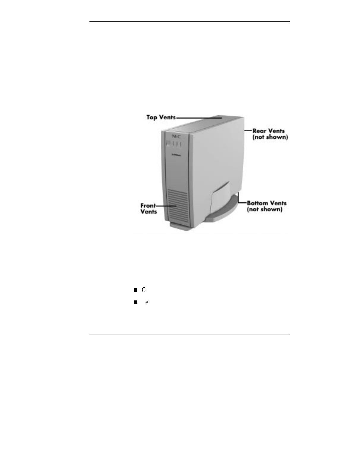
The computer has external vents for cooling and air
flow (see the following figure). To ensure proper
cooling of the computer, keep all vents clear of
obstructions.
To ensure adequate air flow and reduce the risk of
overheating or fire, use the stand provided with your
system for vertical (“tower”) placement of the
computer.
INSTALLATION
Install the computer according to the following procedures
and safety standards:
Computer vents
Check the voltage switch.
Select the system orientation.
Setting Up the Computer 1-3
Connect cables
Prevent internal access.
!
Do not plug in the computer power cable unti l you
connect all other ex ternal cables (keyboar d, mouse,
monitor, LAN, and so on).
The following sections provide installation guidelines and
procedures.
The push-button on/off power switch on the front
panel of the computer does not turn off the AC
power. To remove AC power from the computer,
you must unplug the AC power cable from the
power supply or the wall outlet.
WARNING
!
CAUTION
Checking the Voltage Switch
A 51-watt (rated) power supply is integrated into the
computer. The voltage ratings for the power supply are
provided in the following table.
Power Supply Voltage Rating
VOLTAGE INPUT FREQUENCY (HZ) CURRENT (AMPS)
100-127 60 2
200-240 50 1.25
1-4 Setting Up the Computer
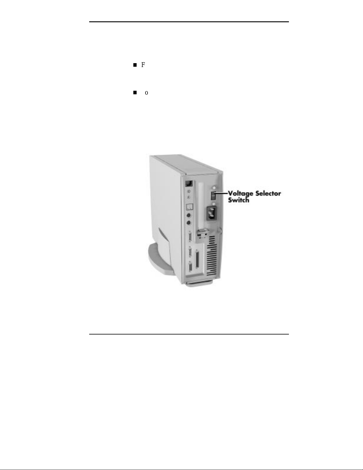
Before connecting the power cable to the back panel of the
computer, make sure that the voltage selector switch is set
to the correct AC line source voltage for your region.
For line voltages between 100 and 127 VAC, set the line
voltage selector on the power supply switch to 115V
(115 VAC).
For line voltages between 200 and 240 VAC, set the line
voltage selector switch on the power supply to 230V
(230 VAC).
Make sure that the correct voltage (115V or 230V) is
visible on the switch (see the following figure). If necessary,
use a flat-head screwdriver to set the switch.
Line voltage switch selector
Setting Up the Computer 1-5
Selecting System Orientation
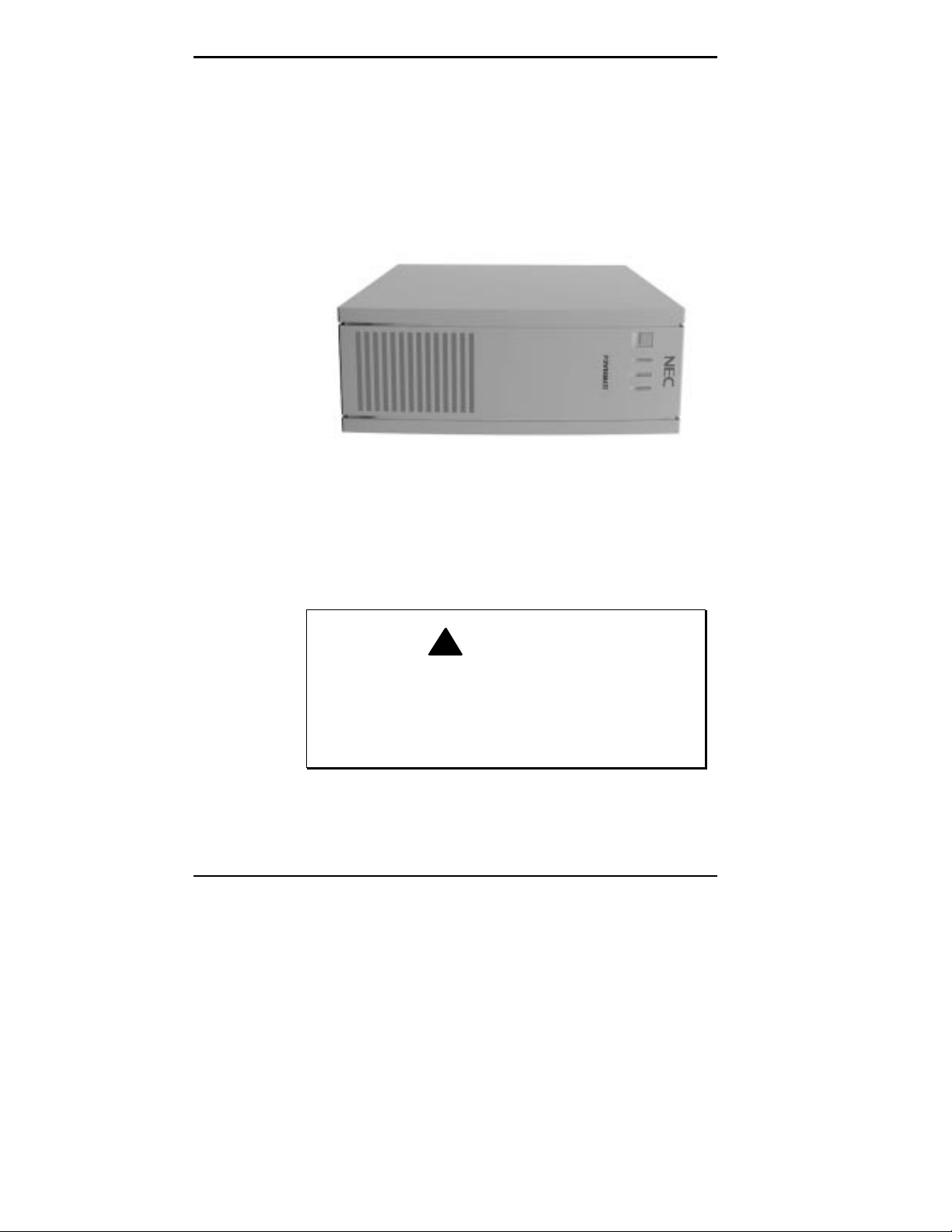
The computer is designed to sit in a horizontal or vertical
position on a desktop or other surface away from the floor.
In the horizontal position, the computer supports standard
15-inch monitors.
Horizontal orientation
For vertical placement, use the stand provided in the
computer shipping box.
To ensure stability, center the unit in the stand as
shown in the foll owing figure. Do not place the unit
in the v er ti cal posit ion wit hout t he stand. Dam age t o
equipment and data may result if the computer
accidentally tips over.
1-6 Setting Up the Computer
!
WARNING
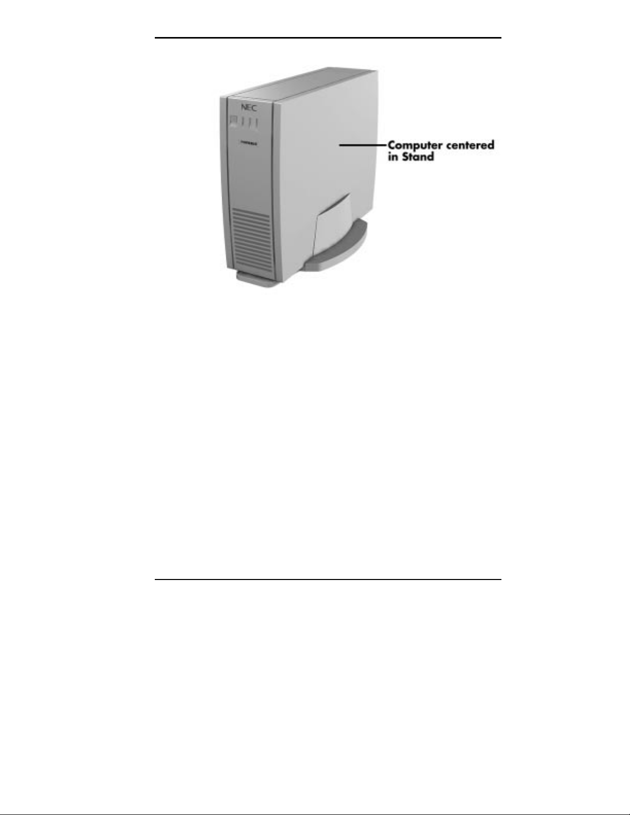
Vertical orientation
Connecting Cables
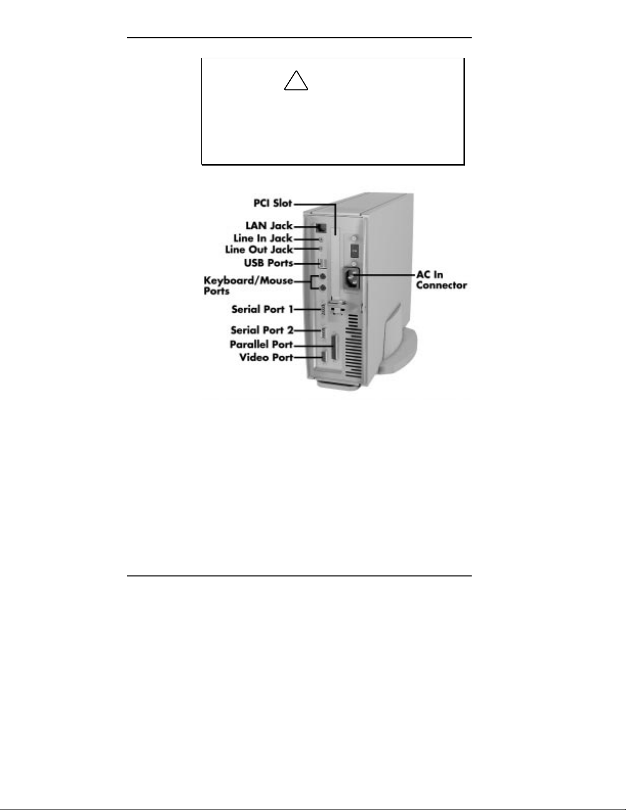
The following figure shows the connector locations on the
back of the computer for connecting the keyboard, mouse,
monitor, and power cables.
The figure also shows the locations for other device cables
in case you are installing additional hardware.
Setting Up the Computer 1-7
!
Turn of f and unplug the c om puter before connect ing
any cables to the back of the computer. Equipm ent
may be damaged if you connect cables while the
power is on. Plug in the power cable only af ter all
other device cables have been connected.
CAUTION
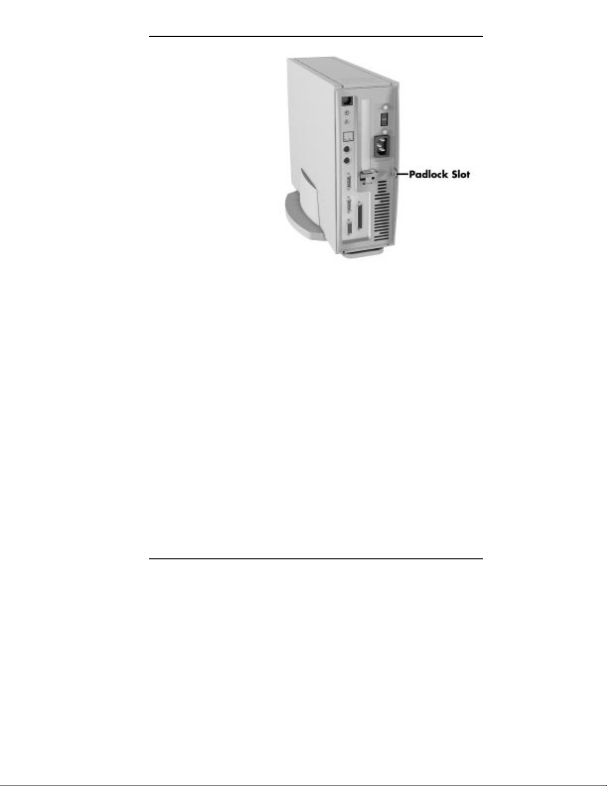
Preventing Internal Access
To prevent access to the inside of the computer, install a
padlock in the small padlock slot in the back of the system
(see the following figure).
1-8 Setting Up the Computer
Rear panel connectors
OPERATION
Chassis security
The following sections provide basic procedures for starting
up and shutting down the computer.
Starting Up
Power on the system using the following steps.
Plug the monitor power cable into a grounded wall
1.
outlet.
Plug the computer’s power cable into the AC power-in
2.
connector on the back panel of the computer and into a
grounded wall outlet.
Setting Up the Computer 1-9

!
Ensure that t he power serv i ce c onnecti on i s thr ough
a properly grounded outlet.
NECCSD recom mends that you pl ug the computer
into a surge suppresser for protection against
sudden transient incr eases or decreases in electrical
power that could damage your computer’s power
supply and result in loss of data.
If the computer does not turn on, press the power button
on the front panel (see the following figure). Use the
lamps on the front panel to verify that the power, hard
disk drive, and LAN connections are working as follows:
Power-on (green)/Sleep mode (yellow)
Hard drive activity (green)
LAN activity (green).
CAUTION
1-10 Setting Up the Computer
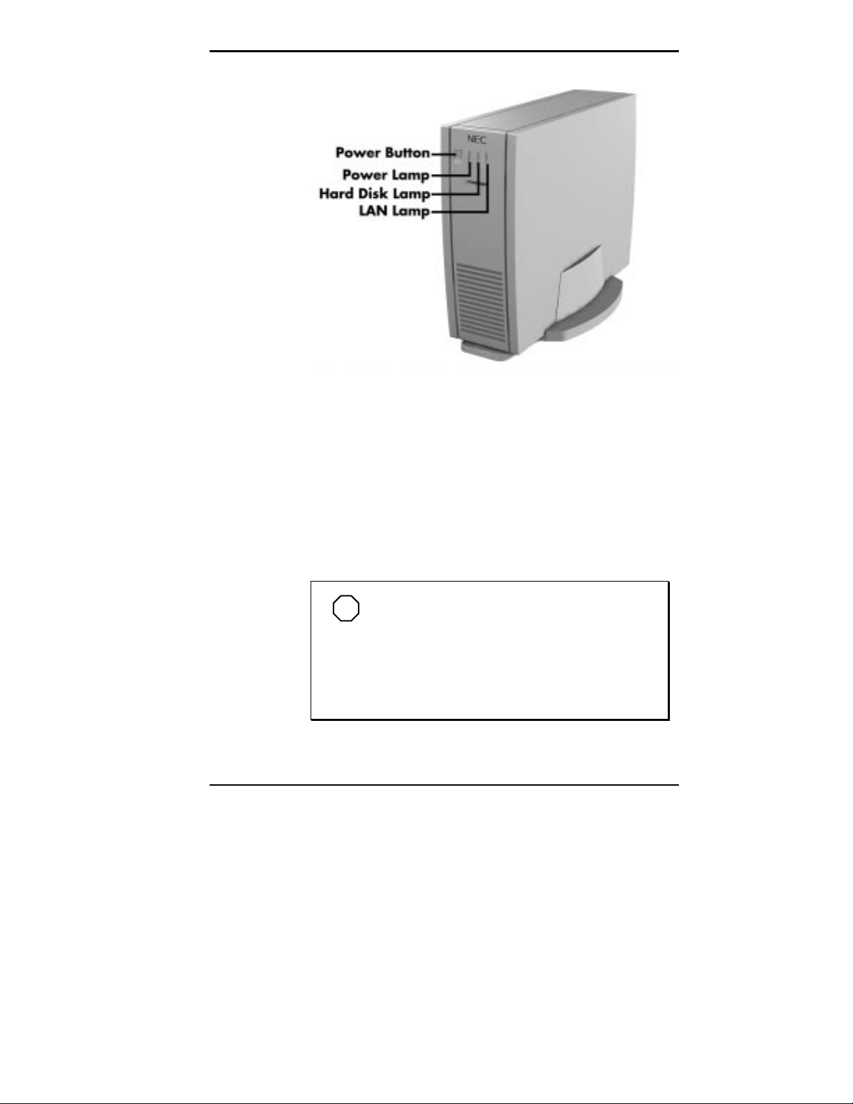
Front panel controls and indicators
The power lamp lights green to indicate that the system is
on. The NEC startup screen appears.
At the bottom of this screen, messages like the following
appear:
Press <F2> key if you want to run Setup
Press ESC to display POST
NOTE
These messages are part of your system’s
Power-On Self-Test (POST). Your computer is
checking your hardware for any changes since the
last startup. If you want to see the messages
displayed during POST, press ESC. If you want to
go into the Setup Utility, press F2.
Setting Up the Computer 1-11

One beep indicates that the system has successfully
completed the power-on test. After about five seconds,
Windows starts up.
If a problem occurs, a series of beeps may sound. If this
happens repeatedly after powering on, power off the system
and turn to Chapter 5, Solving System Problems. This
chapter provides some helpful hints on obvious system
problems.
NOTE
If the system displays a message i ndicating
that system sett ings have changed, run Setup (see
Chapter 2, NECCSD Utilities).
On PowerMate NetPC systems loaded with the
Windows NT
when prompted on-screen to do so. The log-on box appears
for entering a password.
Shutting Down
Follow these steps to shut down (power off) your computer.
1.
2.
3.
®
4.0 operating system, press
Ctrl-Alt-Del
Save your work. See the documentation that comes with
your application.
Exit the application program.
Make sure that the hard disk drive is not in use. A lit
hard disk activity lamp indicates that the drive is in use.
1-12 Setting Up the Computer
!
Wait until a program is finished running before
powering off the system.
Unless absolutely necessary, never power off the
system when the system power lamp is yellow or
when the hard disk activ ity lamp is lit. Information
on the hard disk might be lost or damaged.
CAUTION
4.
Press the Windows
Start
button, then point to and click
“Shut Down.” Selecting “Shut Down” gives you several
choices in the pop-up submenu. Select “Shut down the
computer,” then click the
Yes
button or press
Enter
shut down the computer.
NOTE
A m essage appears inform ing you when it is
safe to turn off your system.
5.
Turn off power to your monitor.
6.
Power off the system by pressing the system unit power
button.
This completes the system setup procedures. For
information about system features, see Chapter 3,
“Reviewing System Features.”
to
Setting Up the Computer 1-13

Using NECCSD
2
THE SETUP UTILITY
Utilities
This chapter provides information about the computer’s
software tools and utility programs. These include:
Setup utility
Flash utility
LANDesk® Client Manager
NEC Auto Backup utility
NEC Select Install CD.
The Setup utility program is used to configure the main
components of the computer.
NOTE
correct system parameters for the configuration.
Unless you add optional har dware, you do not need
to run Setup to operate the system. However, you
might wish to run the Setup utility to set features
that customize the system, such as security
features.
The system ships from the factory with the
Using NECCSD Utilities 2-1
System configuration information is stored in nonvolatile
memory. A nonvolatile memory device retains its data when
system power is turned off. Nonvolatile memory in the
system is stored in a complementary metal-oxide
semiconductor (CMOS) chip backed up by a battery on the
system board. The battery supplies continuous power to
CMOS memory and maintains configuration information
when system power is off.
NOTE
write down the current Setup param eters and store
the inform ation in a safe place. This all ows you to
restore the system t o the current paramet ers if you
ever need to have the battery replaced.
When to Use Setup
The Setup utility lets you view and set system parameters.
Use the Setup utility program to:
NECCSD recommends that you print out or
set the time and date.
update or check system parameters when expansion
options have been added or removed.
change or set power management features.
correct a hardware discrepancy when the Power-On
Self-Test (POST) displays an error message and
prompts you to run Setup.
check the installation of optional memory by comparing
the amount of memory installed with the amount of
memory displayed by Setup.
change certain system operating parameters, such as
boot device sequence and keyboard parameters.
2-2 Using NECCSD Utilities

configure system connections for peripherals, such as
devices connected to the printer port and serial ports.
customize the system with security features such as
passwords, virus check reminder, and system backup
reminder.
set system parameters in the event that the CMOS
battery has been replaced.
How to Start Setup
To start the Setup utility, follow these steps:
Turn on or reboot the system.
1.
2.
Press
after POST to start the memory test before the
F2
system boots up.
There is about five seconds in which to press
the system boot continues.
Setup’s Main menu appears and looks similar to the
following screen.
F2
before
Using NECCSD Utilities 2-3
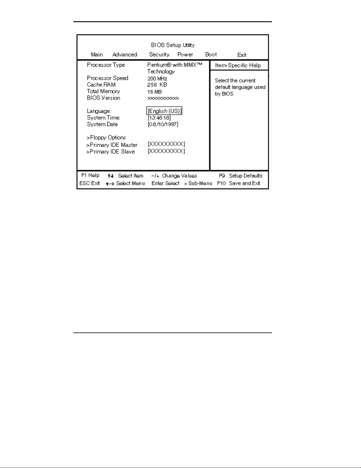
Setup Main menu
How to Use Setup
Use the keys shown on the bottom of the Setup menu to
make your selections or exit the current menu. The
following table describes the navigation keys.
2-4 Using NECCSD Utilities

Navigation Keys
Main Menu
Key
F1 Provides help for the parameter field being
Esc Exits the menu
Enter Executes Command or Selects submenu
↓ or ↑ arrow keys
← or → arrow keys
+ or – Selects parameter values in a menu
F9 Loads the Default Configuration values for
F10 Save and Exit
Function
displayed.
Moves cursor up and down
Selects next menu
this menu
Main menu items preceded by > contain a submenu of
selectable fields for setting system parameters. To display a
submenu, use the arrow keys to move the cursor to the
submenu you want. Then press
Enter
.
Choose the Main menu by selecting Main menu in the
legend bar. Other Main menu options are available by
selecting submenus.
NOTE
See “How to Start Setup” for a look at a
typical Main menu screen.
Use the arrow keys to select one of the following Main
menu options and press
to select a submenu. Items
Enter
with grayed-out text are not available. Explanations of each
menu item follow.
Using NECCSD Utilities 2-5

Displayed Information
The following information is displayed in the Main menu.
These fields are read-only and cannot be changed:
Processor type
Processor speed
Cache RAM
Total Memory
BIOS version.
Language
Selects the current language used by the BIOS. Use this
field to select English (the default) or French.
System Time/Date
Use this menu to set the current time and date. The settings
remain in memory even after the system power is turned off.
To set the time, enter the current hour, minute, and seconds
in hh:mm:ss, 24-hour format. For example, type
for 1:30 P.M.
13:30:00
To set the date, enter the current month, day, and year in
mm/dd/yyyy format. For example, type
September 30, 1997.
Floppy Options
The parameters for this field appear only in Configuration
mode as part of the BIOS recovery procedure described in
Chapter 4. Unless you are recovering the system BIOS in
Configuration mode, all the parameters for this field are set
to “Disabled.”
2-6 Using NECCSD Utilities
09:30:1997
for

Primary IDE
The Primary IDE Master and Slave settings control the
system’s hard disk drive.
The computer comes with the hard disk drive (drive C:)
configured as the “Primary IDE Master.” The system can
support a maximum of two IDE drives (master and slave)
on the primary IDE channel. Menu choices include:
Primary Master
Primary Slave.
The default setting for existing installed Master devices is
“Auto,” meaning that the system automatically detects the
hard disk type and sets the remaining parameters. The
default setting for existing installed Slave devices is
“None.”
If a hard disk drive that does not feature auto IDE type
detection has been installed (or the IDE hard disk was
formatted on another system with parameters different than
those reported by the drive), enter a parameter for each of
the following fields.
Using NECCSD Utilities 2-7

!
W hen set to Auto Detected, the BI OS detects what
the drive is capable of, not the translation
mechanism that was used to format the drive.
If a drive i s run i n a mode other than the mode i n
which it was partitioned and formatted,
unpredictable results may occur, including data loss.
Type
Use this field to enter the hard disk drive type. The
following options are available:
“Auto” automatically configures the device.
“User” prompts the user to fill in the remaining
fields.
“CD-ROM” configures a CD-ROM device.
“IDE Removable” configures a removable IDE
device, such as a tape drive or Zip drive.
CAUTION
“ATAPI Removable” configures a removable
“None” indicates that no device is selected.
Cylinders
Enter the number of cylinders.
Heads
Enter the number of read/write heads.
Sectors
Enter the number of sectors per track.
2-8 Using NECCSD Utilities
storage device that uses the AT attachment packet
interface (ATAPI) standard

Maximum Capacity
This read-only field displays the capacity of the hard
disk drive installed in the system.
Multiple Sector Transfers
Enter the number of sectors transferred per block.
Choices include “Disabled” (no sectors chosen),
“Standard” (one sector), 2, 4, 8, and 16 sectors.
LBA Mode Control
When “Enabled” is selected, it causes logical block
addressing to be used in place of cylinders, heads, and
sectors.
Transfer Mode
Enter the method for transferring the data between the
hard disk drive and the system memory. The Setup menu
only lists those options supported by the drive. Choices
can include
Standard
Fast PIO 1, Fast PIO 2, Fast PIO 3, or Fast PIO 4
FPIO3 and Bus Mastering
FPIO 4 and Bus Mastering.
Ultra DMA Mode
This field sets the Ultra DMA mode, which allows a
faster read/write file transfer rate (33 MB per second).
Choices include Mode 0, Mode 1, and Mode 2. This
setting should be disabled if an older hard disk drive is
installed that is not supported by Ultra DMA mode.
Using NECCSD Utilities 2-9

Advanced Menu
Selecting “Advanced” from the Main menu displays a menu
with the following options.
PnP O/S
The PnP field indicates if the computer’s operating system
is configured to use Plug and Play devices. Choose “Yes” if
you are using a system that has Plug and Play. The default
is “Yes” for Windows 95 systems. For systems without
Plug and Play (such as Windows NT 4.0), this field is set to
“No.”
Reset Configuration Data
Use this setting to clear CMOS (by selecting “Yes” and
rebooting) if the system parameters get corrupted. The
default is “No.”
Memory Cache
Memory cache saves time for the CPU by holding data most
recently accessed in regular memory (dynamic RAM or
DRAM) in a special storage area of static RAM (SRAM),
which is faster. Before accessing regular memory, the CPU
first accesses the cache. If it does not find the data it is
looking for, it accesses the regular memory.
The default for the Memory Cache is “Enabled.” This field
controls both the primary and secondary caches. Setting the
Memory Cache to “Disabled” will hurt performance, but
might be required when running programs that utilize
software-timing loops and need to be slowed down to
execute properly.
Memory Banks 0 and 1
The two Memory Bank fields are read only. They display
the total amount of memory in each DIMM bank.
2-10 Using NECCSD Utilities

Resource Configuration
Memory Reservation
Use this field to reserve specified blocks of upper
memory for use by other ISA devices. Select “Reserved”
to choose a memory block. The default for each block is
“Available.”
The following list includes the available memory blocks:
C800-CBFF
CC00-CFFF
D000-D3FF
D400-D7FF
D800-DBFF
DC00-DFFF
Memory Hole
The default setting for this parameter is “Disabled.”
When set to “Enabled,” this parameter turns system
RAM off to free address space for use with an
option card. When enabled, memory choices are
“Conventional” or “Extended.” Either a 128-KB
conventional memory hole (starting at 512 KB) or a
1-MB extended memory hole (starting at 15 MB) is
created in system RAM.
IRQ Reservation
Use this field to reserve specified IRQs for legacy ISA
cards. Select “Reserved” to choose an IRQ. The default
for each IRQ is “Available.” The following list includes
the available IRQs:
IRQ 3
IRQ 4
IRQ 5
IRQ 7
Using NECCSD Utilities 2-11

IRQ 10
IRQ 11
IRQ 15.
Peripheral Configuration
Adjustments must sometimes be made in the Setup Utility
when peripheral devices are added, removed or changed.
Use the fields in the following list to configure the system
when making any peripheral configuration changes.
Serial Ports A and B
Selectable parameters for this field are “Disabled,”
“Enabled,” and “Auto.” The default setting for
Serial Port A is “Enabled.” The default setting for Serial
Port B is “Disabled.” The serial ports can be auto
detected by choosing “Auto.” The “Auto” parameter
enables the serial device, but the BIOS does not place its
resources unless the “PnP OS” field described
previously is set to “No.”
Use the Enabled setting if you want to choose a specific
address for the serial port. The following options
become available:
Base I/O address
Interrupt
Serial Port B Mode
2-12 Using NECCSD Utilities
Available addresses include “3F8h” (Serial Port A
default), “2F8h” (Serial Port B default), “3E8h,”
and “2E8h.”
Available IRQs include “IRQ3” (Serial Port A
default) and “IRQ4” (Serial Port B default).
If you are using an IrDA device, the Serial Port B
Mode field should be “IrDA.” The default is
“Serial.”

NOTE
When an option is selected for one serial
port, that selection is not available for the second
port.
Parallel Port
Selectable parameters for this field are Disabled,
Enabled (default), and Auto. The parallel port device
can be auto detected by choosing Auto. When Auto is
selected, the first free LPT port is assigned. Setting this
field to Auto enables the device, but the BIOS does not
place its resources unless the “PnP OS” field described
previously is set to “No.”
Select Enabled if you want to choose a specific address.
The following options become available:
Mode
Choices include: “ECP” for setting the parallel port
to the Enhanced Capabilities Port (ECP) mode,
“Disabled,” “Output Only,” and “Bi-directional”
(sets the parallel port to input/output mode only).
The default setting is “Bi-directional.”
Base I/O address
Available addresses include “378h” (the default),
“3BCh,” and “278h.”
Interrupt
Available IRQs include “IRQ5” and “IRQ7” (the
default).
Using NECCSD Utilities 2-13

DMA channel
This field appears only when the Mode option is set
to “ECP”; it does not appear when the Mode option
is set to bidirectional (the default) or the other
parameters. When Mode is set to ECP, DMA
channel choices include “DMA3” (the default) and
“DMA 1.”
Floppy Disk Controller
This field enables the diskette drive interface connector
on the riser board. The default setting is “Disabled.”
IDE Controller
The IDE Controller field enables the IDE interface
connector on the riser board. Choices include “Enabled”
(default) and “Disabled.”
Audio
This field (“Enabled” by default) enables the audio
system on the system board. Choose “Disabled” if an
external audio card is installed.
LAN
This field configures the LAN device. The default
setting is “Enabled.”
Legacy USB Support
This field enables (the default ) or disables support for
legacy Universal Serial Bus (USB) devices.
Hardware Monitor
This field enables (the default) or disables the on-board
hardware monitor device.
2-14 Using NECCSD Utilities

Keyboard Configuration
Use this field to adjust the following keyboard features:
Numlock
This field controls whether the Num Lock key on the
keyboard is “On” or “Off” at bootup. The default setting
for this field is “Auto.”
Key Click
This field turns audible key click on or off. The default
is “Disabled.”
Keyboard Auto-Repeat Rate
This field sets the number of times per second to repeat
a keystroke when the key is held down. Options include
2, 6, 10, 13.3, 18.5, 21.8, 26.7, or 30 clicks per second.
The default is “30.”
Keyboard Auto-Repeat Delay
This field controls the speed characters repeat when a
keyboard key is held down. The higher the number the
faster the repeat. Options include 1/4, 1/2, 3/4, or
1 second. The default is “1/2” second.
Video Configuration
The Video Configuration submenu includes the Palette
Snooping field. This option enables card “snoop” (also
called RAMDAC shadowing) write cycles to the ISA video
card’s palette registers. This field can be either “Enabled”
or “Disabled.” The default is “Disabled.”
This field should only be enabled if all of the following
conditions occur:
An ISA card connects to the PCI graphics card via the
VESA compatible feature connector.
The ISA card connects to a color monitor.
Using NECCSD Utilities 2-15

The card uses the RAMDAC on the PCI card.
The palette snooping feature is broken on the PCI card.
DMI Event Logging
This field keeps track of system events.
Event logging Capacity
For example, space available.
Event Logging Validity
For example, valid.
View DMI Log
Press
Clear all DMI Event Logs
“No” is the default; select “Yes” to clear logs.
Event Logging
The default setting for this field is “Enabled.”
Mark DMI Events As Read
Press
to view the DMI log.
Enter
to mark DMI events.
Enter
Security Menu
The Security menu contains features that enable you to
restrict access to the computer. The Security menu contains
the following fields.
User Password Is
This read-only field lets you determine whether a User
Password has been set. This field can be either “Clear” or
“Set.” The default is “Clear” (no password has been set).
When both the User Password and Supervisor Password are
enabled, only the Supervisor Password gives you full access
to all Setup fields.
2-16 Using NECCSD Utilities

Supervisor Password Is
This read-only field lets you determine whether a
Supervisor Password has been set. This field can be either
“Clear” or “Set.” The default is “Clear” (no password has
been set).
When both the User Password and Supervisor Password are
Enabled, only the Supervisor Password gives you full
access to all Setup fields.
Set User or Supervisor Password
The password fields allow you to enable a user-level
password or supervisor-level password during POST and to
enter Setup.
Use the following procedure to set a password.
Using the arrow keys, select Security from the menu bar.
1.
The Security menu appears.
Select “Set Supervisor Password” or “Set User
2.
Password” with the plus (+) or minus (-) keys.
NOTE
enabled, the Set up Utility can only be accessed by
entering the password.
3.
Once the Supervisor Password feature is
With the password field selected, press
Enter
. Setup
displays a dialog box with the following prompts:
Enter new password: [ ]
Confirm new password: [ ]
Type the password (passwords are not case sensitive)
4.
and press
. Reenter the password and press
Enter
again.
Using NECCSD Utilities 2-17
Enter

Use the arrow keys to select
5.
Select Exit Saving Changes. Press
6.
At the prompt, to confirm exiting setup, press
7.
The password takes effect the next time you power on
the system. You must enter a password the next time
you power on.
Clear User Password
Use this field to clear a User Password. To clear the
password, highlight the field and press
displays a confirmation window. Press
password. If you do not want to clear the password,
highlight
User Setup Access
Use this field to prevent a user from accessing the Setup
utility. The default setting is “Enabled,” which allows the
user to access Setup. To prevent the user from accessing
Setup, highlight the field and press
“Disabled” and press
.
Exit
Enter
Enter
Enter
in the confirmation window and press
No
. Then highlight
Enter
again.
Enter
.
Enter
. Setup
to clear the
Enter
.
.
Using a Password
After you set the password in Setup and reboot the system,
a password prompt appears each time you power on the
system.
To use the password, type the password at the password
prompt and press
NOTE
appear on the screen. Enter the password carefully.
2-18 Using NECCSD Utilities
.
Enter
For security, characters you ent er do not

If you enter the password incorrectly, the system does not
boot. You have three chances to enter the correct password.
After the third unsuccessful attempt, you must reboot the
system and try again.
Dual password security provides two levels of password
security. A supervisor password allows access to the
system’s Setup utility for system configuration. A user
password allows system boot-up only after the entry of a
password.
Unattended Start
This field controls the point at which the user password is
required. The Unattended Start field can only be set if a
user password is in effect.
When this field is set to Disabled (the default setting), the
user is prompted for the password before the system can
boot. The text string prompt “Enter Password (1)” is
displayed.
When this field is set to Enabled and a user password is set,
the system boots and runs, but the keyboard is locked. The
user password must be entered to unlock it. The BIOS does
not display any prompt string.
Using NECCSD Utilities 2-19

Power Menu
Power management reduces the amount of energy used after
specified periods of inactivity. The Power menu provides
the choice of operating the system in a full-on state or a
full-power reduction state when idle.
Power Management
This field allows you to enable or disable the power
management options. Selecting “Enabled” also allows
you to further configure the Power Management options.
Inactivity Timer
This field sets the length of time before the computer
powers down various system devices. Choices for
inactivity time periods include Off, 5, 10, or 20 (the
default) minutes and 1 or 2 hours.
Hard Drive
When this field is enabled, the hard disk drive is
powered down during periods of inactivity. Choices
include “Enabled”(default) and “Disabled.”
VESA Video Power Down
This field enables you to set the video power down level
of inactivity. Choices include “Disabled,” “Sleep” (the
most energy efficient setting), “Suspend,” and
“Standby.” The default is “Standby.”
2-20 Using NECCSD Utilities

Boot Menu
The Boot menu allows you to configure the system’s boot
process.
Scan User Flash Area
The field allows the BIOS to scan the Flash ROM.
Selectable parameters for this field are Disabled and
Enabled. The default is Disabled.
Restore On AC/Power Loss
This field enables you to decide whether the system
automatically boots up or stays off after power is
restored to the system (after an unexpected power loss).
The default setting is “Power On,” which causes the
system to automatically boot up after power restoration.
Choose “Stay Off” if you want the system to stay off.
“Last State” restores the previous power state before the
power loss occurred.
On Modem Ring
This field enables an external modem to work even when
the system is in a power reduction state. Choosing
“Power On” (the default) restores the system to full
power so it can receive a modem ring. Choose “Stay off”
if you do not want full power restored on a modem ring.
On LAN
This field enables the system to be contacted via a LAN
connection even when the system is in a power reduction
state. Choosing “Power On” (default) restores the
system to full power so the LAN connection can be
made. Choose “Stay off” if you do not want full power
restored.
Using NECCSD Utilities 2-21

On PME
This field controls how the system responds to a PCI
Power Management Enable (PME) wake up event. The
choices are “Power On” (the default) and “Stay Off.”
Boot Order
These fields allow you to set the order in which the
system’s drives boot up. The default order is:
Hard disk
®
LANDesk
Service or network
Diskette drive.
Hard Drive
This field lists the bootable hard disk drives in the
system as well as bootable ISA boards. Use this field to
change the booting order.
Removable Devices
This field lists the bootable removable device drives
(diskette, Zip, CD-ROM, etc.) in the system as well as
their booting order. Use this field to change the booting
order.
Boot Time Diagnostic screen
When set to enabled, this field allows you to display the
Diagnostic Screen during boot up. The default setting is
“Disabled.”
Floppy Check
When set to “Enabled,” this field verifies the floppy type
during boot up; “Disabled” (the default) speeds up the
boot. This field is not applicable to the PowerMate
NetPC.
2-22 Using NECCSD Utilities

Exit Menu
Virus Check Reminder
This field displays a reminder message during boot up at
preset intervals (daily, once a week, or once a month).
The default setting is “Disabled.”
System Backup Reminder
This field displays a reminder message during boot up at
preset intervals (daily, once a week, or once a month).
The default setting is “Disabled.”
Fixed Disk Boot Sector
This field write protects the hard disk boot sector to
protect against viruses. Your choices are “Normal” (the
default) and “Write Protect.”
Selecting “Exit” from the menu bar displays the following
exit options.
NOTE
Esc does not exit thi s menu. You m ust select
one of the items from the menu to exit.
Exit Saving Changes
Choose this option if you wish to save any changes made
and exit the Setup program.
Exit Discarding Changes
Choose this option if you wish to exit the program
without saving any changes made.
Load Setup Defaults
Choose this option if you wish to load the original
system BIOS default settings.
Load Custom Defaults
Choose this option to load the custom defaults.
Using NECCSD Utilities 2-23

FLASH UTILITY
The system BIOS resides on a flash read only memory
(ROM) chip in the system. The flash ROM can be updated
with a very simple procedure.
Performing an update is done with a BIOS flash diskette.
The diskette contains the latest version of the BIOS code.
You can obtain the flash diskette from NECCSD or, if a
modem is available, the latest BIOS can be downloaded
from the NECCSD Bulletin Board Service (BBS). See
“NECCSD Bulletin Board Service” in Chapter 4 for the
procedure for logging onto the BBS to download
information.
Save Custom Defaults
Choose this option to save any changes as custom
defaults. Normally, the BIOS reads the setup parameters
from CMOS, but if the CMOS fails, the BIOS will read
the custom defaults (if you set them). If not, the BIOS
uses the factory default settings.
Discard Changes
Choose this option if you wish to discard any changes
made in the current session, but want to continue to
enter new changes.
Update the BIOS from the BIOS flash diskette by using a
configuration server such as Intel’s LANDesk
Configuration Manager or proceed as follows.
NOTE
connect an ext ernal diskette driv e (with a separat e
power supply) to the diskette driv e connec tor on the
riser board.
2-24 Using NECCSD Utilities
The following procedure requires that you

Write down the Setup parameters currently set on the
1.
system.
Turn off the system.
2.
Insert the flash diskette into drive A and turn on the
3.
system.
When the flash upgrade menu appears, choose “Update
4.
Flash Memory Area from a file.”
When the menu asks you to enter a path/filename, use
5.
the arrow keys to select the “.bio” file and press
The utility asks for a confirmation that you want to load
6.
Enter
.
the new flash into memory. Select “Continue with
Programming.”
After the upgrade completes, remove the upgrade
7.
diskette.
Reboot the system and start the Setup program. Press
8.
to reset the BIOS defaults. Then, use the copy of the
F9
Setup selections you made at the beginning of this
procedure to set the parameters.
LANDESK CLIENT MANAGER
LANDesk Client Manager (LDCM) is a software program
available on the NEC Select Install CD. LDCM uses the
Desktop Management Interface (DMI) standard to manage
components (network interface cards, memory, software
applications) within a Client (local) or remote (workstation)
PC system. It provides features for managing the resources
of a local PC and can be used by system administrators to
manage groups of computer systems.
See “NEC Select Install CD” for instructions on installing
LANDesk Client Manager on the NetPC hard disk.
Using NECCSD Utilities 2-25

With Client Manager you can perform the following tasks:
review system inventory of workstation hardware and
software components
view DMI-compliant component information
troubleshoot
receive notice of system events (for example, if the
system is running low on memory, you are notified of
the potential problem)
detect changes to CPU, memory, and hard disk
characteristics and alert you to these changes
transfer files to and from client workstations
remotely reboot client workstations.
There are two main components of Client Manager: PC
Health Indicator and Inventory.
PC Health Indicator
PC health indicator consists of three parts:
Workstation management
PC Health meter
PC Health description.
Workstation Management
Client Manager sets up a connection to all the workstations
running on the network to allow the administrator to
monitor the functions of each workstation.
The monitoring is in real time so that if an unhealthy
workstation is fixed, you can refresh the screen to view the
new correct PC health. You can also set the monitor to
report only unhealthy workstations.
2-26 Using NECCSD Utilities

PC Health Meter
The PC Health meter is a traffic signal that provides a
visual indicator of workstation health.
A red light indicates that a critical system event has
occurred. You are required to fix the problem
immediately.
A yellow light or noncritical system event requires that
you monitor the situation. It may be a problem that
could get worse and become a critical event.
A green light indicates everything is working fine with
the system.
PC Health Description
The description of PC health is determined by monitoring
various system components for threshold levels. Some of
the components that are monitored include:
drive space
prediction of hard drive failure with automatic data
backup (see “NEC Auto Backup Utility for further
information)
free virtual memory
temperatures
power supplies
chassis opened
non-critical boot failure
boot virus detection.
Once a threshold level has been passed on a workstation,
you can request notification of the problem and have it
written into a log file.
Using NECCSD Utilities 2-27

Inventory
Client Manager Inventory views the hardware and software
components of the workstation. The inventory consists of
the following categories:
workstation summary
basic hardware
drives
memory
audio
keyboard/mouse
video
system resources
I/O ports
operating system
network
applications
system files
user information.
You can also view the current system configuration, edit
user information, and create or restore file snapshots.
2-28 Using NECCSD Utilities

DMI
The Desktop Management Interface (DMI) is the
industry-standard used to manage system components on
the computer. The PowerMate NetPC uses this standad
along with LANDesk Client Manager to ensure
interoperability among different vendor’s computers.
Examples of system components are network interface
cards and software applications. System components
provide a Management Information Format (MIF) file to be
DMI-compliant. The information file describes component
attributes that can be managed.
Client Manager can be used to “get” attribute information
on system components. It can also be used to “set” attribute
values in real time.
More information on DMI is available on the World Wide
Web at
http:\\www.dmtf.org
Monitoring Capabilities
The PowerMate NetPC computer has a chip (NEC
MagicEye™ technology) mounted on the system board that
supports many new and advanced real-time monitoring
capabilities used by DMI. This chip provides the following
features:
.
an integrated temperature sensor with configurable
interrupt generation based on upper and lower
temperature limits
a power supply monitor with configurable interrupt
generation based on upper and lower voltage limits
chassis intrusion detection with interrupt generation
capabilities.
Using NECCSD Utilities 2-29

To take advantage of these features, DMI has expanded its
interface in the following areas:
Interrupts may be enabled or disabled.
High and low limits can be set and are displayed for
temperature and power supply voltages.
Current readings are displayed for temperature, power
supply voltages, and chassis state.
Interrupts can be detected when “out of range”
conditions occur. User prompts are displayed to alert the
user to a potentially harmful condition.
NEC AUTO BACKUP UTILITY
The NEC Auto Backup utility is a data management and
backup program (available on the NEC Select Install CD)
that operates in conjunction with LANDesk’s DMI and the
Self-Monitoring Analysis and Reporting Technology
(S.M.A.R.T) Hard Drive instrumentation. If the
S.M.A.R.T. drive identifies a potential problem, the NEC
Auto Backup utility automatically invokes the Cheyenne
Backup program and backs up the entire file system to a
user-selected backup device, such as a Zip drive, network
drive, or tape.
NEC Auto Backup can also do regularly-scheduled backups
and scan files for viruses during a backup operation.
NOTE
Cheyenne Backup must be preconf igured. See the
NEC Auto Backup utility “Read Me” file for
information about Cheyenne Backup.
2-30 Using NECCSD Utilities
For the NEC Auto Backup utility to work,

See “NEC Select Install CD” for instructions on installing
the NEC Auto Backup utility on the NetPC hard disk.
NEC SELECT INSTALL CD
The system comes with an NEC Select Install compact disc
(CD). This disk contains all the system software files. Use
the NEC Select Install CD to download the operating
system and application software from a hardware/software
service platform, such as LANDesk Configuration Manager
(LCM). Should a problem occur that causes data loss or
corruption, you can restore the system files using the NEC
Select Install CD.
The Select Install CD installs all or part of the computer’s
software in two phases:
operating system (OS) restore program
selective application restore program.
The OS restore phase allows you to install Windows 95 or
Windows NT from the LCM CD-ROM reader. If you need
to do a full restore, start with phase one.
Phase two, the Selective Application Restore program,
takes place while the OS is running and lets you choose the
application software you want to install. Use phase two for
installing selected applications from the LCM CD-ROM
reader at any time.
Both the OS and application phases use easy-to-understand
dialog boxes and screen messages so you can smoothly
proceed through the installation process.
The following sections explain how to use the NEC Select
Install CD with LCM.
Using NECCSD Utilities 2-31

Operating System Restore
OS Restore is the first phase of a full system installation.
To perform an OS Restore, the System Administrator must
create a service and download the operating system from the
Select Install CD in the LCM CD-ROM reader. The Client
(user) completes the restore process by selecting the service
and running the OS Restore program on the PowerMate
NetPC system.
Follow these steps to restore the original, factory-installed
operating system using OS Restore.
Insert the NEC Select Install CD into the LCM
1.
CD-ROM reader.
Do a map connection to the CD-ROM reader.
2.
From the LCM desktop, double click
and right click on the CD-ROM drive. (For example,
right click on
designated as drive E.)
In the popup menu, right click on
E:/Properties screen appears.
My Computer
if the LCM CD-ROM reader is
E:
Sharing
. The
In the Properties screen, click
Click the
Share Name field. (For example, type
the field.)
Click OK. This returns you to the Properties screen.
Using universal naming code (UNC), set up a service on
3.
the LCM to run the OS Restore program
(OSRESTOR.BAT).
Press
Configuration Service Manager program from the
Intel LANDesk submenu.
2-32 Using NECCSD Utilities
New Share
, then highlight
Start
Shared As
.
button, then type a name in the
in
Programs
CD-ROM
and select the

The Configuration Service Manager Connect screen
appears.
Click the
Connect
button.
The Configuration Service Manager screen appears.
This screen has four tabs: Services, Menus, Users,
and Activity Log.
Make sure the
button. The Service Wizard screen appears.
New
Type a Service Definition name (maximum of 25
Services
tab is selected, then click the
characters) in the Service Definition field. For
example, type
Using the left mouse button, put a check mark in the
netpc-1
in the field.
“Setup applications and run programs” box by
clicking once in the box.
Click the
In the Text and Description field, type in the service
Next
button.
text that a user sees in the service boot menu
(maximum of 80 characters). For example, type
NetPC System Setup
.
Type any additional information in the optional
Description of Service field that you want displayed
when the user highlights the service.
Click the
button. The Confirmation Message
Next
screen appears.
Put a check mark in the “Show a confirmation
message” box by clicking once in the box. Then type
the message in the text box.
If you do not want a Confirmation Message to
appear, make sure the default “Do NOT show a
confirmation message” box is checked.
Using NECCSD Utilities 2-33

Click the
button. The Setup Applications and
Next
Run Programs screen appears.
Click the
button. The Preparing for Application
Add
Setup/Run Program screen appears.
Put a check mark in the “Yes, the files are located on
the Configuration Server” box by clicking once in the
box.
Using UNC, enter the full path and name for the
CD-ROM’s OS Restore program. For example,
type
\\LCM_0081\CD-ROM\OSRESTOR.BAT
. (If
necessary, use the browse button to find the
program.)
Click OK.
The program you are running appears in the Setup
Applications and Run Programs screen.
Click the
Select the following optional settings:
Next
button.
Closing Message (type the message in the text
box, then click
Next
)
Administrator’s Note (type the note in the text
The Service Wizard Finish screen appears.
Click the
The new Service icon (in this example, “netpc-1”)
appears in the Configuration Service Manager
screen.
If you click once on the icon, the Service properties
appear on the right side of the screen.
2-34 Using NECCSD Utilities
box, then click
Finish
button.
Next
).

Add the new Service to a previously created menu
that a user sees (for example, NetPC Main Menu).
Click the
Menus
tab.
Highlight the menu in the Available Menus list.
Click
Edit
.
In the Menu Editor screen, Available Service appears
on the lower left, and Displayed Services is on the
lower right.
In Available Service, highlight the new Service and
click the
button. This adds the service to the
Add
Displayed Services list.
Click OK.
The new Service loads into the data base, and its icon
appears in the Configuration Service Manager screen
in the Services window.
Press the File pull down menu, then select
Yes
.
click
NOTE
This complet es the steps done by the System
Admini strator. The remai ning steps are done by the
Client (user) on the PowerMate NetPC.
Exit
and
Turn on the NetPC. At the prompt, press the spacebar to
4.
remotely log onto the LCM.
Enter the User logon name and password.
5.
An Intel screen for the previously defined LANDesk
Configuration menu appears with the new Service.
Highlight the Service name, then press
6.
Using NECCSD Utilities 2-35
Enter
.

If a Confirmation Message window appears, click
7.
continue.
The Operating System Restore Welcome screen appears.
Welcome Screen
to
C
Click
8.
program).
A License Agreement screen appears with three options:
Back, Reject, and Accept.
The
The
The
of the license and allows you to continue.
2-36 Using NECCSD Utilities
Continue
button returns you to the Welcome screen.
Back
Reject
Accept
to continue (or
to exit the
Exit
button terminates the restoration process.
button signals that you accept the terms

9.
Click
Accept
to continue.
The Restore Mode screen appears (see the following
figure) with three options: Back, Auto, and Custom.
The
button returns you to the License
Back
Agreement screen.
The
button selects a restore process designed
Auto
for local PCs configured with CD-ROM readers.
!
The Auto button does not f unc ti on i n the PowerMat e
NetPC system. Do
System failure may result.
The
Custom
WARNING
not
press the Auto button.
button selects a restore process for
system administrators who want control of restore
functions in networking environments.
10.
Click
Custom
(instead of
Auto
) on the Restore Mode
screen so you do not partition and format the hard disk
before restoring the OS (see the following figure).
Restore Mode Screen
Using NECCSD Utilities 2-37

After you click
Custom
, a Partitioning the Hard Drive
screen appears with options allowing you to retain the
present partition structure (by selecting
Skip
) or
partition the hard disk using FAT16 or FAT32 (by
selecting
Continue
The Continue button does not function in the
PowerMate NetPC system. Do
Continue button. System failure or data corruption
may result.
).
!
WARNING
not
press the
11.
Click
the Hard Drive screen to retain the present partition
structure on the hard disk.
The Format Mode screen appears with four options:
Back, Exit, Quick, and Full.
2-38 Using NECCSD Utilities
Skip
Click
screen.
Click
Partitioning the Hard Drive Screen
(instead of
Back
to return to the Partition Information
Exit
to terminate the restore process.
Continue
) on the Partitioning

Click
Click
to do a quick hard disk format.
Quick
to do a full hard disk format.
Full
Format Mode Screen
After you click
Quick
or
, the Installing
Full
Applications screen appears (see the following figure),
indicating the status of the restore process as the
operating system loads from the CD.
Installing Application Screen
Using NECCSD Utilities 2-39

NOTE
The drivers and other software components
required for the operating system are also loaded
from the CD.
When the OS finishes loading, the Operating System
12.
Restore Completed screen appears. Remove the CD
from the LCM CD tray.
13.
Click
Continue
to reboot. Windows loads and sets up
the system’s devices and environment.
Selective Application Restore Program
After the operating system is up and running, the System
Administrator can begin phase two, allowing installation of
the applications associated with the OS. Use this process to
reinstall selected applications at any time.
Place the Select Install CD in the LCM CD tray.
1.
On the Client desktop, double click
2.
Neighborhood
Double click
3.
to the LCM CD-ROM reader.
Double click on the
4.
The NEC Selective Application Restore Program screen
appears.
.
Entire Network
selrest.exe
Network
and do a map connection
program.
2-40 Using NECCSD Utilities

NOTE
Only the applicat ions that work with the
system’s OS appear in the Select Install Program
screen. For exam ple, if the OS is W indows 95, but
there are applications for both Windows 95 and
Windows NT 4.0 on the CD, only the drivers
required for Windows 95 appear.
Selective Application Restore Program Screen
Select the applications you want to install by double
5.
clicking on the item box or line. A check mark appears
in the box.
To unselect an item, double click it again so that the
check mark disappears.
Using NECCSD Utilities 2-41

NOTE
Items that appear grayed-out are already
installed on the system.
Click OK.
6.
The application files reload sequentially, and a progress
bar appears for each application selected.
When all the applications have finished installing,
7.
remove the CD.
8.
Click
Restart Computer
to reboot and ensure that the
installation process completes successfully.
2-42 Using NECCSD Utilities

Reviewing System
3
Features
PowerMate NetPC systems are available in two basic
models with the following features:
Windows® 95 operating system, 166-MHz Intel
Pentium® MMX processor, 16 MB (minimum) of
Synchronous Dynamic Random-Access Memory
(SDRAM), and a 2.0-GB IDE hard disk drive
Windows NT® 4.0 operating system, a 200-MHz Intel
Pentium MMX processsor, 32 MB of SDRAM, and a
3.2-GB hard disk drive.
The MMX processor technology boosts audio, video, and
3D graphics performance.
Both PowerMate NetPC models come with an RJ-45
network connector and a video adapter with 2 MB of
Synchronous Graphics Random-Access Memory
(SGRAM).
®
Both models also contain audio/video components for
multimedia presentations and support optional memory
expansion modules. For further hardware enhancements,
both models contain a PCI expansion slot for adding an
optional, 1/2-length PCI board.
In addition, you may upgrade the system’s hard disk by
ordering one of several Ultra DMA/33-compatible IDE hard
disk options available from NECCSD.
Reviewing System Features 3-1

!
Access to the inside of the computer is restricted
and subject to warranty requirements. Use
NECCSD-authorized personnel to perform system
upgrades.
WARNING
Depending on the model, the system might ship with the
following software installed on the hard disk:
Microsoft® Windows NT 4.0 or Windows 95
Healthy Environment Help file
Intel Pro100 Ethernet network drivers
S3 3D Virge/GX video drivers
Active Movie video drivers
Yamaha audio drivers
Microsoft Internet Explorer
Microsoft Windows NT 4.0 or Windows 95 Bus Master
IDE drivers
Mouse drivers for Windows NT 4.0 or Windows 95.
CDs containing copies of the operating system and the
following applications are included in the shipping carton:
McAfee® VirusScan® and WebScan™
LANDesk® Client Manager
NEC Auto Backup utility
Cheyenne Backup utility
FirstAid Deluxe™ 97.
3-2 Reviewing System Features

SYSTEM CHASSIS
The chassis provides an enclosure for the system board,
power supply, a riser card with one PCI expansion slot and
RJ-45 network connector, a fan, and one storage device
slot.
The storage device slot supports a single one-inch high,
3 1/2-inch IDE hard disk that is compatible with the Ultra
DMA/33 standard for high-speed data transfers. (Non-Ultra
DMA/33 compatible IDE devices are also supported.)
SYSTEM BOARD COMPONENTS
The PowerMate NetPC system board has the following
components.
Processor
Depending on the model, processing for the system is
provided by the 166-MHz or 200-MHz Intel Pentium MMX
microprocessor.
The processor integrates a 16-KB internal cache and a
256-KB secondary cache and cache controller to improve
system performance. An integrated math coprocessor
increases the speed of floating point operations.
System Memory
The system comes in configurations starting with a
minimum of 16 MB of system memory. Two 168-pin
sockets on the system board support up to 256 MB of highspeed memory using industry-standard, gold-plated, 168-pin
dual in-line memory modules (DIMM).
Reviewing System Features 3-3

NOTE
An additional approved vendor list (AVL),
10-ns or 12-ns, Synchronous Dynamic Random
Access Memory (SDRAM) DIMM can be installed
into the open memory socket.
Memory can be installed in one socket or both. The memory
type, size, and speed can vary between sockets. The system
automatically detects the memory; no jumper settings are
required. The DIMMS can be either single- or double-sided.
The minimum allowable memory size for the system is
8 MB, and the maximum is 256 MB.
The following table describes supported DIMM modules.
Supported DIMMs
DIMM SIZE TYPE CONFIGURATION TECHNOLOGY
8 MB CAS Latency 2 SDRAM 1 M x 64 16 Mbit
16 MB CAS Latency 2 SDRAM 2 M x 64 16 Mbit
32 MB CAS Latency 2 SDRAM 4 M x 64 16 Mbit
64 MB* CAS Latency 2 SDRAM 8 M x 64 16 Mbit
128 MB* CAS Latency 2 SDRAM 16 M x 64 64 Mbit
*64-MB and 128-MB modules are supported when available.
3-4 Reviewing System Features

Interrupt Controller
The interrupt controller operates as an interrupt manager
for the entire system environment. The controller accepts
requests from peripherals, issues interrupt requests to the
processor, resolves interrupt priorities, and provides vectors
for the processor to determine which interrupt routine to
execute. The interrupt controller has priority assignment
modes that can be reconfigured at any time during system
operations.
The interrupt levels are described in the following table.
Interrupt-level assignments 0 through 15 are in order of
decreasing priority. See “The Setup Utility” in Chapter 2
for information on changing the interrupts using the Setup
utility.
Interrupt Level Assignments
INTERRUPT PRIORITY INTERRUPT DEVICE
IRQ00 Counter/Timer
IRQ01 Keyboard
IRQ02 Cascade (INT output from slave)
IRQ03 COM2 and COM4
IRQ04 COM1 and COM3
IRQ05 Audio (if present)
IRQ06 Diskette Drive Controller
IRQ07 Parallel Port 1
IRQ08 Real-time clock
IRQ09 S3 Video and USB
IRQ10 Available
IRQ11 Available
IRQ12 PS/2 mouse
Reviewing System Features 3-5

Interrupt Level Assignments
INTERRUPT PRIORITY INTERRUPT DEVICE
IRQ13 Coprocessor
IRQ14 Primary IDE
IRQ15 Available
PCI Local Bus
The 32-bit industry-standard PCI bus is a highly integrated
input/output (I/O) interface that offers the highest
performance local bus available for the Pentium-based
processor. The PCI bus supports burst modes that send
large chunks of data across the bus, allowing fast displays
of high-resolution images.
The high-bandwidth PCI local bus eliminates data
bottlenecks found in traditional systems, maintains
maximum performance at high clock speeds, and provides a
clear upgrade path to future technologies.
The PCI bus contains the embedded PCI local bus IDE
interface and supports the video controller.
Flash ROM
The Flash ROM allows fast, economical BIOS upgrades.
Flash ROMs are reprogrammable system and video
EPROMs.
With a Flash ROM, a ROM BIOS change:
is fast and easily done using a Flash utility
eliminates the expensive replacement of ROM BIOS
chips, and reduces system maintenance costs
reduces inadvertent system board damage that can take
place when replacing ROMs
3-6 Reviewing System Features

facilitates adopting new technology while maintaining
corporate standards
gives network administrators company-wide control of
BIOS revisions.
Information on how to use the Flash utility is provided in
Chapter 2, Using NECCSD Utilities.
Graphics Features
The system features a PCI local bus motion video playback
controller and graphics accelerator (S3 Virge/GX)
contained on a single chip on the system board.
NOTE
of the S3 Virge/GX graphics chip on the system
board. If you install your own graphics card in the
PCI expansion slot, its features may be different.
The following sections describe the features
Motion Video Controller
The motion video controller integrates a Windows graphical
user interface (GUI) engine and motion video playback
hardware. This means you can view 3D graphics and
movies on the computer.
Support includes:
MPEG-1 or MPEG-2
Video for Windows
Active Movie (Windows 95 only).
Reviewing System Features 3-7

MPEG is a compression/decompression standard developed
by a professional video group called the Motion Picture
Experts Group. MPEG produces full-resolution,
30-frames-per-second (fps), broadcast-quality digital video.
Graphics Accelerator
The graphics accelerator is specifically designed for
graphics-intensive operations, 3D effects, texture mapping,
text and color pixel amplification, and scrolling. The
graphics accelerator provides 64-bit, ultra-high
performance for demanding True Color, High Color, and
pseudocolor GUI and computer-aided design (CAD)
applications.
The accelerator minimizes bus traffic by off-loading the
tasks normally performed by the processor. The dedicated
bit-block transfer (BitBLT) engine maximizes performance
by speeding the movement of large blocks of image data in
video memory.
Video Support
The system has 2 MB of Synchronous Graphics RAM
(SGRAM) on the system board.
The system supports the following resolutions, colors, and
refresh rates for systems with 2 MB of video memory.
3-8 Reviewing System Features

Supported Refresh Rates
REFRESH RATE (HZ)
RESOLUTION
640 x 480 60 60, 70, 72, 75,85 60, 72, 75, 85 60, 72, 75, 85
4-BIT COLOR
(16 COLORS)
8-BIT COLOR
(256
COLORS)
15-/16-BIT
COLOR (32K/64K
COLORS)
24-BIT COLOR
(16M
COLORS)
800 x 600 56, 60, 72,
1024 x 768 43 (IL), 60,
1152 x 864 Not supported 60 Not supported Not supported
1280 x 1024 43 (IL), 60,
1600 x 1200 Not supported 48.5 (IL), 60 Not supported Not supported
IL = Interlaced
K = thousand
M = million
75, 85
70, 75, 85
75, 80
56, 60, 72, 75,85 56, 60, 72, 75,
43 (IL), 60, 70,
75, 85
43 (IL), 60,
75, 85
85
43 (IL), 60, 70,
75, 85
Not supported Not supported
56, 60, 72, 75,
85
Not supported
High-Speed Communication Ports
The system features an enhanced parallel port and two
buffered high-speed serial ports.
The enhanced parallel port supports Enhanced Capabilities
Port (ECP) and Enhanced Parallel Port (EPP) modes for
devices that require ECP or EPP protocols. These protocols
allow high-speed bidirectional transfer over a parallel port
and increase parallel port functionality by supporting more
devices.
The buffered high-speed serial ports support transfer rates
up to 115.2 kilobytes (KB) per second. These ports allow
the installation of high-speed serial devices for faster data
transfer rates.
Reviewing System Features 3-9

RJ-45 Port
IDE Port
The combination of the enhanced parallel port and buffered
serial ports ensure optimum performance for future
peripheral devices and operating systems.
The rear of the system contains an RJ-45-compatible
network port for connection to an Ethernet network. This
allows you to communicate with the server and share files
with other computers on the network.
The system board in the computer supports one internal
IDE port.
The port supports two IDE devices, one set as master on the
IDE channel, the other as slave. For system configuration
flexibility, the computer allows the logical connection of an
IDE device without the addition of a controller. (Physically,
only one hard disk fits in the chassis.)
The IDE port supports the Ultra DMA/33 standard for
33.3 MB per second, 32-bit wide data transfers on the highperformance PCI local bus.
NOTE
The system supports only one Ultra DMA/33
device on the IDE channel. If an additional IDE
devi ce is added to the IDE channel, nei ther dev ice
can use Ultra DMA/33 mode.
USB Ports
The Universal Serial Bus (USB) ports allow you to add new
serial devices without opening up the system — simply plug
them into the ports. The USB determines system resources
for each peripheral and assigns them without user
intervention. Up to 127 devices can be daisy chained to a
single USB port.
3-10 Reviewing System Features

Sound System
The Yamaha sound system installed on the system board
provides compatibility with Sound Blaster Pro™, Sound
Blaster™ 2.0, Ad Lib™, MPU-401, and Microsoft®
Windows Sound System™ for PC sound applications.
For detailed sound specifications, see the “System
Specifications” in Appendix B.
Plug and Play Support
The computer comes with a Plug and Play BIOS that
supports Plug and Play technology. Plug and Play
eliminates complicated setup procedures for installing Plug
and Play expansion boards.
With Plug and Play technology, you add a Plug and Play
expansion board simply by powering off the system,
installing the board, and powering on the system. There are
no jumpers to set and no system resource conflicts to
resolve. Plug and Play automatically configures the board
for the system.
The system also supports non-Plug and Play boards.
Reviewing System Features 3-11

24-Hour Information
4
Services
NECCSD has made it easy for you to get information and
help when you need it. We offer 24-hour information
services via the following services described in this chapter:
NECCSD FaxFlash™ Service
NECCSD Bulletin Board Service
NECCSD on America Online® Service
NECCSD on CompuServe® Online Service
E-mail to NECCSD Technical Support Services through
a commercial online service or the Internet
Fax Service to NECCSD Technical Support Services
NECCSD Web and FTP Sites
NECCSD Technical Support Services (U.S. customers
only).
If you have access to a modem and/or fax machine
(telephone for Technical Support), you can use the above
services to obtain information about your system at any
time, day or night, seven days a week.
Not only do these services provide general information
about your system, they can also be used to answer your
questions and help solve any problems you may have with
your system, should that ever be necessary.
24-Hour Information Services 4-1

NECCSD FAXFLASH SERVICE
The NECCSD FaxFlash service is a self-help, automated
electronic information service for obtaining up-to-date
product application notes, installation procedures,
troubleshooting tips, data sheets, technical information
bulletins, illustrated parts lists, part numbers, and other
information about your system.
Using a fax machine, you can obtain information from
FaxFlash 24 hours a day, 7 days a week. Simply call the
FaxFlash number on your touch-tone telephone and order
the information you want by following the voice prompts.
FaxFlash automatically faxes the information to you.
If you are new to FaxFlash, first order one of the following
catalogs. Each catalog lists the available documents and
their document numbers. Current catalogs include:
Catalog 1, NECCSD Telephone Directory and Online
Service Information
Catalog 3, NECCSD Computer Product Specifications,
Warranty Policy, Ultracare Guidelines, and Sales
Information
Catalog 5, NEC ProServa™ and Express Serva Product
Information
Catalog 6, NEC Ready Consumer Desktop Systems
Catalog 7, NEC PowerMate Commercial Desktop
Systems
Catalog 8, NEC Portable Systems (including Versa
Notebook and MobilePro™ Handheld computers).
Catalogs 5, 6, 7, and 8 contain technical support
information, including Technical Information Bulletins,
Illustrated Parts lists, Frequently Asked Questions (FAQs)
lists, and other product support documents.
4-2 24-Hour Information Services
®

Order information from FaxFlash as follows.
Be sure that your fax machine or fax/modem is on. Have
1.
the document number ready for the document you want.
At your touch-tone telephone, enter
2.
and Canada) or
Listen to the instructions provided by the voice prompts.
3.
Press
if you do not want an introduction to FaxFlash.
1
508-635-6090
888-329-0088
(international)
(USA
Follow the automated instructions for ordering your
document or catalog.
Press
if you want an introduction to FaxFlash. Follow
2
the automated instructions for ordering your catalog or
document.
When prompted, enter your fax number and name.
4.
For international use, first enter the international long
distance access number (
), your country code, your
011
area code or city code, then your fax number.
FaxFlash automatically sends the information you request
to your fax machine. Please wait for the ordered document
to arrive at your fax machine before calling to order more
documents. If FaxFlash attempts to send the second order
before the first order is completed, the order may be
canceled. After three tries, FaxFlash assumes that your line
is busy and terminates any further processing of the order.
24-Hour Information Services 4-3

NECCSD BULLETIN BOARD SERVICE
Through your network connection (or if you have access to
a modem), you can use the NECCSD Bulletin Board
Service (BBS) to get the latest information on hardware and
software. The BBS allows you to download files (video
drivers, printer drivers, BIOS updates, etc.) for system
enhancements and upgrades.
The BBS can also be accessed through the CompuServe
online service.
Log onto the BBS as follows.
From the Windows desktop, click the
1.
Point to Programs. Point to Accessories and then click
2.
HyperTerminal
Double click the
3.
.
Hypertrm.exe
icon. The
Start
button.
HyperTerminal program appears.
Follow the instructions on the screen to set up your
4.
modem. Click the
HyperTerminal
help button for
information about dialing the phone number.
If you need to check communications settings, check that
the settings match the following BBS parameters.
Baud rate: select any baud rate that matches your
modem
Parity: none
Data bits: 8
Stop bits: 1
Flow control: Xon/Xoff (select Hardware if using
14.4 bps or higher).
4-4 24-Hour Information Services

Following the HyperTerminal instructions, enter the
5.
BBS phone number (
508-635-4706
phone system and/or location might require a
). Your business
or
9 1
1
prefix.
NOTE
The first time that you use the BBS, you are
requested to provide information for a new user
questionnaire.
Press
6.
Enter your first name, last name, and password. Press
7.
Enter
Follow the screen prompts until the Main Menu is
8.
twice.
Enter
after each.
displayed.
At the Main Menu, select
9.
Conference 1
From the Main Menu, press
10.
for the desktop conference.
to join a conference. Select
J
and
F
Enter
for the File
menu.
At the File menu, select
11.
for a list of downloadable
F
files. Follow the prompts to select a file for
downloading.
!
Executable files automatically format your diskette
when you download files f rom the BBS. Form atting
destroys any data on the diskette. Before you
download fil es from the BBS, check that you do not
have information on the diskette that you need.
CAUTION
24-Hour Information Services 4-5

After you complete downloading your file, log off the BBS
as follows:
Press
1.
Press G (command for Goodbye/Hangup).
2.
Press
3.
Enter
Enter
(to continue).
.
NECCSD ON AMERICA ONLINE SERVICE
If you subscribe to America Online, you can use the service
to obtain information about NECCSD and its products.
You can use America Online to e-mail technical questions
to NECCSD Technical Support staff, post technical
questions and messages on the Message Board, and access
the NEC Software Library to download files.
Use the following steps to access America Online and
NECCSD online information services.
Log onto America Online.
1.
At the opening screen, click
2.
At the Go To menu, click
3.
At the prompt, type
4.
NEC
Go To
Keyword
, then press
in the Main Menu.
.
.
Enter
At the NEC menu, double click one of the following
5.
topics, then follow the prompts:
About NEC
Terms and Conditions
News
Product Information
Questions and Answers
NEC Promotions
4-6 24-Hour Information Services

Message Board
Software Library.
Exit anytime by double clicking the rectangle in the
6.
upper left corner of the screen.
NECCSD ON COMPUSERVE ONLINE SERVICE
If you subscribe to CompuServe, you can use the service to
obtain information about NECCSD and its products. You
can use CompuServe to e-mail technical questions to
NECCSD Technical Support staff, post technical questions
and messages on the Bulletin Board, and access the
NECCSD BBS.
NOTE
You cannot download information from the
NECCSD Bulletin Board from CompuServe. You
must call the NECCSD B ullet in Boar d dir ectly using
the procedure described earlier in this chapter.
Use the following steps to access CompuServe and
NECCSD online information services.
Log onto CompuServe.
1.
At the opening screen, click the Go button, then type
2.
NECTECH
At the NEC menu, double click one of the following
3.
at the prompt, and click OK.
topics, then follow the prompts:
NEC Bulletin Board
Information About This Service
Access NEC BBS
24-Hour Information Services 4-7

Access CompuServe Information Services
Exit.
Exit anytime by double clicking on the rectangle in the
4.
upper left corner of the screen.
E-MAIL/FAX TECHNICAL SUPPORT SERVICE
The NECCSD Technical Support Center offers technical
support by e-mail over the Internet network if you have a
modem. The Internet address is:
tech-support@neccsd.com
You can also fax technical questions to the NECCSD
Technical Support Center if you have access to a fax
machine or fax/modem. The fax number is:
(508) 635-4100
When using the e-mail or fax support service, you should
include the following words in the subject field for prompt
response from the appropriate technical person:
Desktop
Notebook.
You should provide as much specific information about
your questions as possible. Also, if you are sending a fax,
please include your voice telephone number and your fax
number with the question. You will receive a response to
your questions within one business day.
4-8 24-Hour Information Services

INTERNET
If you have a modem, you can access the NECCSD Home
Page on the Internet World Wide Web. You can do this
through a commercial online service or through your
Internet account. The NECCSD Home Page contains
general information about NECCSD products.
You can also use the Internet to access the NECCSD FTP
(file transfer protocol) site to download various files (video
drivers, printer drivers, BIOS updates). The files are
essentially the same files as on the NECCSD Bulletin Board
Service.
To access the World-Wide-Web NECCSD Home Page,
enter the following Internet Uniform Resource Locator
(URL) through your service:
http://www.nec-computers.com/
To access the NECCSD FTP site, enter the following
Internet ftp address through your service:
ftp.nectech.com
Once in the file menu, follow the prompts to choose and
download the file(s) you want.
24-Hour Information Services 4-9

NECCSD TECHNICAL SUPPORT SERVICES
NECCSD also offers direct technical support through its
Technical Support Center. (NECCSD technical support is
for U.S. and Canadian customers only; international
customers should check with their sales provider.)
Direct assistance is available 24 hours a day, 7 days a
week. Call the NECCSD Technical Support Center, toll
free, at 1-800-632-4565 (U.S. and Canada only) for the
following support.
System hardware — toll-free phone support is limited to
the length of the standard warranty.
For hardware support after the standard warranty, get
system hardware support for a fee.
Preinstalled software — toll-free phone support for
90 days from the time of your first call to the NECCSD
Technical Support Center.
After the initial 90 days, get preinstalled software
support for a fee.
Please have available your system’s name, model number,
serial number, and as much information as possible about
your system’s problem before calling.
For outside the U.S., please contact your local NECCSD
sales provider.
4-10 24-Hour Information Services

Solving System
5
Problems
Occasionally, you may encounter a problem with your
computer. In most cases, the problem is one that you can
solve yourself.
Your system has a built-in checking program that
automatically tests its components when you turn the
system unit power on. If there is a problem, the system
displays an error message. If this happens, follow any
instructions on the screen.
If screen messages do not help or an error message does not
appear, refer to the following information in this chapter to
determine and solve the problem:
“Finding Solutions to Common Problems”
Refer to this section to solve common minor problems.
“Getting Help”
Refer to this section if the above listed procedures have
failed to correct the problem.
FINDING SOLUTIONS TO COMMON PROBLEMS
See the following sections to match your problem area and
view the possible causes and solutions.
When trying to solve problems, you should note what the
system was doing when the problem occurred and what you
attempted to do to correct the problem. This information is
useful if you request assistance.
Solving System Problems 5-1

System Problems
Check the following list to match your problem and see the
possible cause and solution.
No power and power lamp not lit.
Check that all power switches are on.
Check that the power cable is plugged into the system
power socket. Check that the other end of the cable is
plugged into a live, properly grounded AC power outlet
or surge protector.
Check the outlet or surge protector by plugging in a
lamp.
System does not boot and error message displayed
on screen.
Run the Setup Utility (see Chapter 2). Check that the
parameters are set correctly, particularly if you just
installed an option.
System emits continuous beeps.
Turn the system off, wait at least five seconds, and turn
the system on. If the beeps continue, call your NECCSD
dealer or the NECCSD Technical Support Center.
System does not maintain date, time, system
configuration information.
Have qualified personnel change the battery. For
assistance, call your NECCSD dealer or the NECCSD
Technical Support Center.
5-2 Solving System Problems

System performance appears sluggish.
Check that your system is set for optimal operation. See
your operating system documentation.
Check the memory requirements of your software
applications. If required, have qualified personnel install
additional DIMM memory. For assistance, call your
NECCSD dealer or the NECCSD Technical Support
Center.
User password forgotten.
Clear the password and reset it. See “Clear User
Password” and “Set User or Supervisor Password” in
Chapter 2.
Monitor Problems
Check the following problems to see the possible cause and
solution.
Monitor screen is dark or the display is hard to
read.
Check that the monitor is on.
Check that the monitor power cable is connected to the
monitor and a power outlet, the monitor signal cable is
connected to the system, and the brightness and contrast
controls are adjusted.
Press the space bar or move the mouse to take the
system out of the power management mode.
Distorted image appears on your monitor screen.
Adjust the monitor’s video controls. If this does not help,
turn the monitor off for several seconds, then back on.
Solving System Problems 5-3

There is constant movement on the screen.
A magnetic field is affecting your monitor. Move any
devices (fan, motor, another monitor) that generate
magnetic fields away from your monitor.
The screen display is fuzzy or flickering; graphics
characters or garbage appears on the screen.
Check that your monitor is set up correctly and that all
connections have been made.
Check that the video refresh rate and video driver are
correct.
Click the right mouse button anywhere on the Windows
desktop and a menu appears. Click on Properties and the
Display Properties window appears.
Keyboard/Mouse Problems
Check the following problem to see the possible cause and
solution.
Mouse or keyboard does not respond.
You may have connected the mouse and keyboard after
turning on your system. Turn the system off, make sure
the mouse and keyboard are connected, and turn the
system back on.
Image appears on screen but nothing happens
when you use the mouse or keyboard.
Tighten the keyboard or mouse cable connection.
If this does not help, turn off the system, wait five or
more seconds, and turn on the system.
5-4 Solving System Problems

GETTING HELP
If you tried correcting problems yourself and were not
successful, you may want to try one or more of the
following 24-hour services for answers to your questions.
(Some services require a modem or fax machine.)
See Chapter 4 for detailed information about using these
services. If you still need help, continue with the
suggestions that follow.
NECCSD FaxFlash Service
NECCSD Bulletin Board Service
NECCSD on America Online Service
NECCSD on CompuServe Online Service
E-mail to NECCSD Technical Support Services through
a commercial online service or the Internet
Fax Service to NECCSD Technical Support Services
Internet
NECCSD Technical Support Services.
Getting Help From Your Company
If you are in a company, the best source of help may be
internal. Your company may have designated central
support personnel to whom you can go when you have
problems.
Getting Help From Your NECCSD Dealer
The NECCSD dealer from whom you purchased your
system is a good source of help and should be contacted.
The dealer is backed by complete support resources and
programs within NECCSD.
Solving System Problems 5-5

Getting Help From NECCSD Technical Support Center
Help is available to you through the NECCSD Technical
Support Center. (International customers should check with
their sales provider.)
Direct assistance is available 24 hours a day, 7 days a
week. Call the NECCSD Technical Support Center, toll
free, at 1-800-632-4565 (for the U.S. only) for following
support.
System hardware — toll-free phone support is limited to
the length of the standard warranty.
For hardware support after the standard warranty, get
system hardware support for a fee.
Preinstalled software — toll-free phone support for
90 days from the time of your first call to the NECCSD
Technical Support Center.
After the initial 90 days, get preinstalled software
support for a fee.
Before calling, please have ready your system name, model
number, serial number, and purchase date. Also have ready
as much information as possible about the problem you are
having, including any error messages that occurred.
5-6 Solving System Problems

NECCSD Warranty/Non-Warranty Repair Service
NECCSD repair service is designed to support your
warranty and non-warranty service activity.
Before you call for repair service, see the previous sections
in this chapter to determine if you can solve the problem
yourself, within your company, through your dealer, or with
the help of a technician from the NECCSD Technical
Support Center.
If your system requires repair service from NECCSD, call
1-800-632-4565 (United States and Canada only).
If you are outside the U.S. and Canada, please contact your
local NECCSD sales provider.
Solving System Problems 5-7

Setting Up a Healthy
A
MAKING YOUR COMPUTER WORK FOR YOU
Work Environment
!
Prolonged or improper use of a computer workstation
may pose a risk of serious inj ury. To reduce your ri sk of
injury, set up and use your computer in the manner
described in this appendix.
Contact a doctor if you experience pain, tenderness,
swelling, burning, cramping, stiffness, throbbing, weakness, soreness, tingling and/or numbness in the hands,
wrists, arms, shoulders, neck, back, and/or legs.
Computers are everywhere. More and more people sit at
computers for longer periods of time. This appendix explains
how to set up your computer to fit your physical needs. This
information is based on ergonomics — the science of making
the workplace fit the needs of the worker.
WARNING
Some nerve, tendon, and muscle disorders (musculoskeletal
disorders) may be associated with repetitive activities,
improper work environments, and incorrect work habits.
Examples of musculoskeletal disorders that may be
associated with certain forms of repetitive activities include:
carpal tunnel syndrome, tendinitis, tenosynovitis, de
Quervain’s tenosynovitis, and trigger finger, as well as
other nerve, tendon, and muscle disorders.
Setting Up a Healthy Work Environment A-1

Although some studies have shown an association between
increasing hours of keyboard use and the development of
some musculoskeletal disorders, it is still unclear whether
working at a computer causes such disorders. Some doctors
believe that using the keyboard and mouse may aggravate
existing musculoskeletal disorders.
Some people are more susceptible to developing these
disorders due to preexisting conditions or psychosocial
factors (see “Preexisting Conditions and Psychosocial
Factors” later in the appendix).
To reduce your risk of developing these disorders, follow the
instructions in this appendix. If you experience discomfort
while working at your computer or afterwards, even at night,
contact a doctor as soon as possible. Signs of discomfort
might include pain, tenderness, swelling, burning, cramping,
stiffness, throbbing, weakness, soreness, tingling and/or
numbness in the hands, wrists, arms, shoulders, neck, back,
and/or legs.
A-2 Setting Up a Healthy Work Environment

ARRANGE YOUR EQUIPMENT
Arrange your equipment so that you can work in a natural
and relaxed position. Place items that you use frequently
within easy reach. Adjust your workstation setup to the
proper height (as described in this appendix) by lowering
the table or stand that holds your computer equipment or
raising the seat height of your chair. To create more desk
space, you can put your computer base on the floor.
Adjust
your chair
Adjust
your keyboard
and mouse
Adjust
your monitor
Setting Up a Healthy Work Environment A-3

ADJUST YOUR CHAIR
Your chair should be adjustable and stable. Vary your
posture throughout the day.
Check the following:
Keep your body in a relaxed yet upright position. The
backrest of your chair should support the inward curve
of your back.
Use the entire seat and backrest to support your body.
Tilt the backrest slightly backwards. The angle formed
by your thighs and back should be 90° or more.
A-4 Setting Up a Healthy Work Environment

Your seat depth should allow your lower back to com-
fortably contact the backrest. Make sure that the backs
of your lower legs do not press against the front of
the chair.
Extend your lower legs slightly so that the angle between
your thighs and lower legs is 90° or more.
Place your feet flat on the floor. Only use a footrest
when attempts to adjust your chair and workstation fail
to keep your feet flat.
Be sure that you have adequate clearance between the
top of your thighs and the underside of your workstation.
Use armre sts or forearm supports to support your forearms.
If adjustable, the armrests or forearm supports should
initially be lowered while all the other adjustments discussed in this appendix are made. Once all these adjustments are completed, raise the armrests or adjust the
forearm supports until they touch the forearms and allow
the shoulder muscles to relax.
Setting Up a Healthy Work Environment A-5

ADJUST YOUR INPUT DEVICES
Follow these points in positioning your keyboard and
mouse.
Position your keyboard directly in front of you. Avoid
reaching when using your keyboard or mouse.
If you use a mouse, position it at the same height as the
keyboard and next to the keyboard. Keep your wrists
straight and use your entire arm when moving a mouse.
Do not grasp the mouse tightly. Grasp the mouse lightly
and loosely.
Adjust the keyboard height so that your elbows are near
your body and your forearms are parallel to the floor,
with your forearms resting on either armrests or forearm
supports, in the manner described previously. If you do
not have armrests or forearm supports, your upper arms
should hang comfortably at your sides.
Adjust your keyboard slope so that your wrists are
straight while you are typing.
A-6 Setting Up a Healthy Work Environment
 Loading...