

NEC PowerMate MB MC32M/B-H, PowerMate MB MC34L/B-H, PowerMate MB MG32M/B-H, PowerMate MB MG34L/B-H User Manual
User's Guide
2
5
9
12
MB Model
This User's Guide contains information primarily specific to this computer, assuming that the user is able to perform basic Windows operations and
understands how to use help in its installed applications to resolve problems. In this user's guide, unless specified, "Windows 8.1" refers to
Windows
[User Account Control] screen comes up, please be sure to confirm the contents before continuing.
The information contained within this manual applies to the following models:
®
8.1 Pro 64-bit system. System configuration and software installation should be conducted by a user who has administrator privileges. If a
• MB Model: MC32M/B-H, MC34L/B-H, MG32M/B-H, MG34L/B-H
Note:For details about a model number, please see “Model number list” (p.24).
1
Checking Included Accessories .............................................2
Connecting Included Accessories ..........................................2
3
Windows Setup ......................................................................3
4
Knowing the Parts ..................................................................6
1
Mouse.....................................................................................8
6
LAN Function..........................................................................8
7
Opening and Closing Covers ...............................................10
Note:The illustrations, screenshots, icons, and on-screen text shown in this document may differ from the ones you actually encounter.
8
Memory ............................................................................... 13
PCI board/PCI Express x16/x1 board ................................. 14
10
System Configuration .......................................................... 16
11
Security Chip Function ........................................................ 17
Applications ......................................................................... 18
13
Recovery ............................................................................. 19
Appendix ............................................................................. 23

Checking Included Accessories
1
2
Checking that all included accessories are present
Please open up the box and check that all included items and accessories are there.
Please immediately contact the place of purchase if any items happen to be missing
or damaged.
1. Check contents of the box.
保修书
修理サ−ビス保証規定書
安全使用说明
Instructions For Safe Use
安全にお使いいただくために
NEC软件的使用条件 【即EULA】(对顾客的特别提示)
Terms and Conditions for using software (For Customer)
ソフトウェアのご使用条件(お客様へのお願い)
Base unit Power cord
DisplayPort to DVI-D adapter Keyboard
Mouse Stand
Cable stopper Application Disc
Recovery Disc
*1 : Included with models MC32M/B-H and MC34L/B-H
*2 : Included with models MG32M/B-H and MG34L/B-H
*3 : Included with models MG32M/B-H and MG34L/B-H (Japanese versions)
*1
*3
*1
*2
*3
(请务必先仔细阅读如下内容后,决定是否打开本个人电脑的包装)
(Please read this before opening the package)
*2*3
User's Guide
*2
*3
*1
2. Confirm that the model number and serial number on the base unit matches
the model number and serial number written on the warranty.
If they happen to differ, please contact the place of purchase immediately. Please
also keep your written warranty in a safe place for future reference.
If your encounter a breakdown during the warranty period, we shall provide repairs
based on the conditions specified in the warranty.
For repairs after the warranty period has expired, please consult the place of
purchase or one of our specified customer service locations. If it is deemed possible
to regain functionality, we are able to perform paid repairs at the customer's request.
Connecting Included Accessories
Important points when connecting
• Do not touch connector terminals when connecting any items.
Failure to do so may cause damage.
• Connect the LAN cable, only after completing Windows setup and firewall
configuration.
This ensures that your computer can be safely connected to a network.
Connecting power sources
1. Attaching the Stands
This computer includes Stands that keep your computer stable when it is positioned
vertically. When you position the computer vertically, attach one or two Stands to
ensure that it will not fall over.
Stands are not necessary when the computer is positioned horizontally.
In such a case, proceed to "2. Connect the keyboard and the mouse" (p.2).
1 Pull out the rear end of the Stand, and place the Stand where you wish to
place the computer.
Pull out the Stand until it is locked and you hear a click sound.
2. Connect the keyboard and the mouse
1 Connect the purple keyboard port to the purple keyboard port ( ).
2 Connect the mouse to a USB port ( or ).
2
3. Connect the display
3
2
Connect your display to the computer using either a digital connector or an analog
connector.
If you will use the dual display function, connect the second display after Windows
Setup has finished.
Connecting a digital LCD display
1 The LCD display has the DVI signal cable on its rear panel. Connect this
DVI cable to the "DisplayPort to DVI-D" adapter and secure it by tightening
the setscrews.
2 Check the icon and the connector shape at the other end of
DisplayPort to DVI-D adapter, and connect it to the DisplayPort socket.
Connecting an analog LCD display
1 Make sure the analog RGB cable connected to the back of the LCD display
matches the icon ( ) and shape of the computer's analog RGB port, and
then attach the cable to the computer's analog RGB port and secure it by
tightening the screws.
4. Connect the power cord and the ground wire
1 Insert the power cord plug into an AC wall outlet.
There may be different ways of connection depending on the type of the
display.
2 Connect the power cord to the computer.
If a ground wire is attached to the supplied power cord, connect it to the ground
terminal of the AC wall outlet.
Windows Setup
When you first power up your new computer, it is necessary to perform Windows
setup.
Important points during setup
• Always follow the procedure written in the manual.
Setup may not be able to be successfully completed if you omit any steps, press
any keys other than the ones indicated on the screen, or operate any switches.
• Do not connect any external peripherals.
Never connect any peripherals (printers, memory, etc.) other than the items
outlined in " Connecting Included Accessories" (p.2). Please connect or install
such peripherals after " Windows Setup" had been completed.
• Do not connect a LAN cable.
To ensure safe network connection, only connect a LAN cable after Windows
setup and firewall configuration has been completed.
• Do not turn off the power during setup.
The setup program is running normally even if the screen appears to stop. Please
keep following the steps in the manual.
• Do not leave the computer alone during setup.
Do not leave the computer unattended until Windows setup has completed
including passing all the screens which require your key operations, and power
OFF.
Preparation for setup
During Windows setup, you are required to enter the name of the person who will be
using the computer (user name), as well as the computer name. Please choose
these names in advance.
3
3 Insert the other end of the power cord into an AC wall outlet.
Although the power may turn on and off after a few seconds, the machine is not
broken.
For the user name and computer name, use single-byte alphanumeric characters only
(20 or less).
If the following symbols or if certain strings are used for any part of the user name or
computer name, Windows setup may not be completed and some applications may
not run correctly.
• Double-byte characters, single-byte Kana characters, non-standard characters, all
symbols, spaces
• Restricted strings
CON, PRN, AUX, CLOCK$, NUL, COM1-COM9, LPT1-LPT9, NONE
3

Turning on the power
1 Turn on the display.
2 Press the power switch ( ).
Never turn off the power during Windows setup. Turning off the power switch or pulling
out the power cord in the middle of this process may lead to damage. If there is a
problem or you accidentally press the power switch, please see "If you encounter
problems during setup" (p.4).
Setup Procedure
Start Windows 8.1 setup.p.
Please contact your system administrator for the appropriate settings in steps 1, 4 and 6.
1 When [Region and language] is displayed, set the [Time zone] and click
[Next] to continue.
If you wish to change the [Country or region], [App language], or [Keyboard layout],
after the setup process has finished, select [Clock, Language, and Region] from the
[Control Panel] and change them.
2 Please check the contents when the [License terms] page is displayed.
3 After confirming the contents, click [I accept].
4 When the personal setting screen appears, select a desired color, enter the
[PC name], and click [Next] to continue.
Setup cannot progress to the next step unless you enter a valid PC name.
5 When the setting screen appears, check the easy setup, and click [Use
express settings].
6 Enter your user name and password when prompted and click [Finish].
If you encounter problems during setup
If you accidentally turn off the power during setup
The setup process will not be successfully completed and Windows system files or
the registry may be corrupted.
In this case, either perform Windows recovery or consult your place of purchase.
The computer is unresponsive or shows an error message during setup
Make a note of the error message and hold down the power switch for at least
four seconds to perform a forced shutdown.
Please wait for at least five seconds before turning the power switch back on. After
that, please see the above "If you accidentally turn off the power during setup".
Using and configuring your computer after setup is complete
If the Windows license is not authenticated yet (Windows 8.1)
If the [Activate Windows] screen is displayed, activate the Windows system via the
Internet or by phone call.
<Activation via Internet>
1 Click [Go to PC settings].
When the computer is connected to the Internet, the Windows system is
activated automatically.
<Activation by phone call>
1 Click [Go to PC settings].
2 Click [Activate by phone].
Follow the on-screen instructions and call the indicated phone number to obtain
the confirmation ID.
Activate the Windows system using the confirmation ID.
You cannot complete this step without entering the user name.
The screen should change several times during this process, and it may take some
time before the start screen is displayed.
4
Creating multiple hard disk partitions
As a default setting, the first internal hard disk has only one useable partition
(volume), designated as the C:drive.
However, it is possible to divide drive C: into multiple partitions.
Please refer to the following steps if you would like to change the factory default
settings and reduce the size of the C: drive in order to create a new partition from the
resulting unassigned space.
1 Click [Desktop] on the start screen.
2 Display the charm bar on the desktop, and click [Settings].
3 Click [Control Panel].
4 Click [System and Security] and then [Administrative Tools].
5 Double click [Computer Management].
6 On the tree displayed on the left side of the window, click [Storage] [Disk
Management].
7 Select the volume marked as (C:) and right click it.
8 Click [Shrink Volume].
9 Enter the desired size into the [Enter the amount of space to shrink in MB] box.
The size entered here will become the maximum size of the newly created partition.
10 Click [Shrink].
11 After shrinking is complete, select the unassigned space that has been
reserved, and right click it.
12 Click [New Simple Volume].
13 Click [Next].
14 Enter the desired volume size into the [Simple volume size in MB] box and
click [Next].
15 Confirm that [Assign the following drive letter] is selected and click [Next].
16 Confirm that [Format this volume with the following settings] is selected
and click [Next].
17 Click [Finish].
Creating a "Recovery Drive"
We recommend that a "Recovery Drive" be created for times when problems such as
corrupted files result in Windows not loading correctly.
For creation of "Recovery Drive," please refer to "Creating a recovery drive"
(p.23).
For information on using "Recovery Drive," please refer to "Using the Windows
function" "If the computer does not start up" (p.22).
If you are using model MG32M/B-H or MG34L/B-H, you cannot create a recovery
drive. If Windows does not start normally, set up the system again using the included
"Recovery Disc."
Windows®Update and Microsoft®Update
The latest updates and important updates are available through Windows
or Microsoft® Update. Please run Windows® Update or Microsoft® Update regularly
to ensure you always have the latest version of Windows installed.
Your computer has been delivered to with the all current updates already installed.
Please do not attempt to uninstall these updates as it may cause issues that have
already been resolved to reappear.
®
Update
• Do not select [Mark Partition as Active] for the newly created partition.
• It is not possible to shrink the [Recovery Partition].
• It is possible to change the drive letter if necessary.
• Depending on the system environment, there may be some cases where
[Shrink Volume] is not possible.
Disk management usage instructions [Disk Management] help.
5
Knowing the Parts
4
(1)
(2)
(23)
(4)
(5)
(14)
(15)
(18)
(12)
(11)
(7)
(9)
(10)
(20)
(18)
(24)
(17)
(13)
(21)
(3)
(6)
(22)
(4)
(3)
(8)
(10)
(16)
(19)
(25)
(5)
Communication speed LED
Network communication/
Connection LED (ACT/LINK)
LAN port
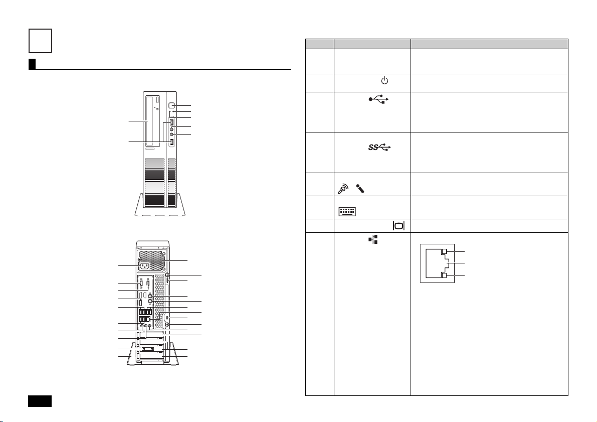
Names and descriptions of your computer's major components
The front side
The back side
Explanation of Components
Number Name Explanation
(1) Optical drive
(2)
Power switch ( )
(3)
USB port ( )
(4) USB port (supports
USB 3.0) ( )
Mic terminal (mini jack)
(5)
) ( )
(
(6) PS/2 keyboard port
()
(7)
Analog RGB port ( )
(8)
LAN port ( )
This computer features either a built-in DVD Super
Multi drive or a built-in DVD-ROM drive. The type of
drive varies by model.
This is used to turn the computer on/off or change
the power state.
This port can be used to connect to USB devices.
This USB port supports both USB 2.0 and USB
1.1. In order to take advantage of USB 2.0 transfer
speeds, it is necessary to be connected to a USB
2.0 enabled device.
This port can be used to connect to USB devices.
This USB port supports USB 3.0, USB 2.0, and
USB 1.1. In order to take advantage of USB 3.0
transfer speeds, it is necessary to be connected to
a USB 3.0 enabled device.
A terminal used to connect microphones and input
audio signals.
A port used to connect a PS/2 (MiniDIN 6-Pin)
keyboard.
A port used to connect an analog interface display.
A port used to connect a LAN cable.
6
• Communication speed LED
- Lights orange when connecting to a 1000
Mbps network.
- Lights green when connecting to a 100 Mbps
network.
- Does not light when connecting to a 10 Mbps
network.
• Network communication/Connection LED
(ACT/LINK)
Flashes when data is being read from or written
to the network.
Also lights when receiving link pulses from a hub
or switch. However, the data may not necessarily
be being read from or written to this computer.
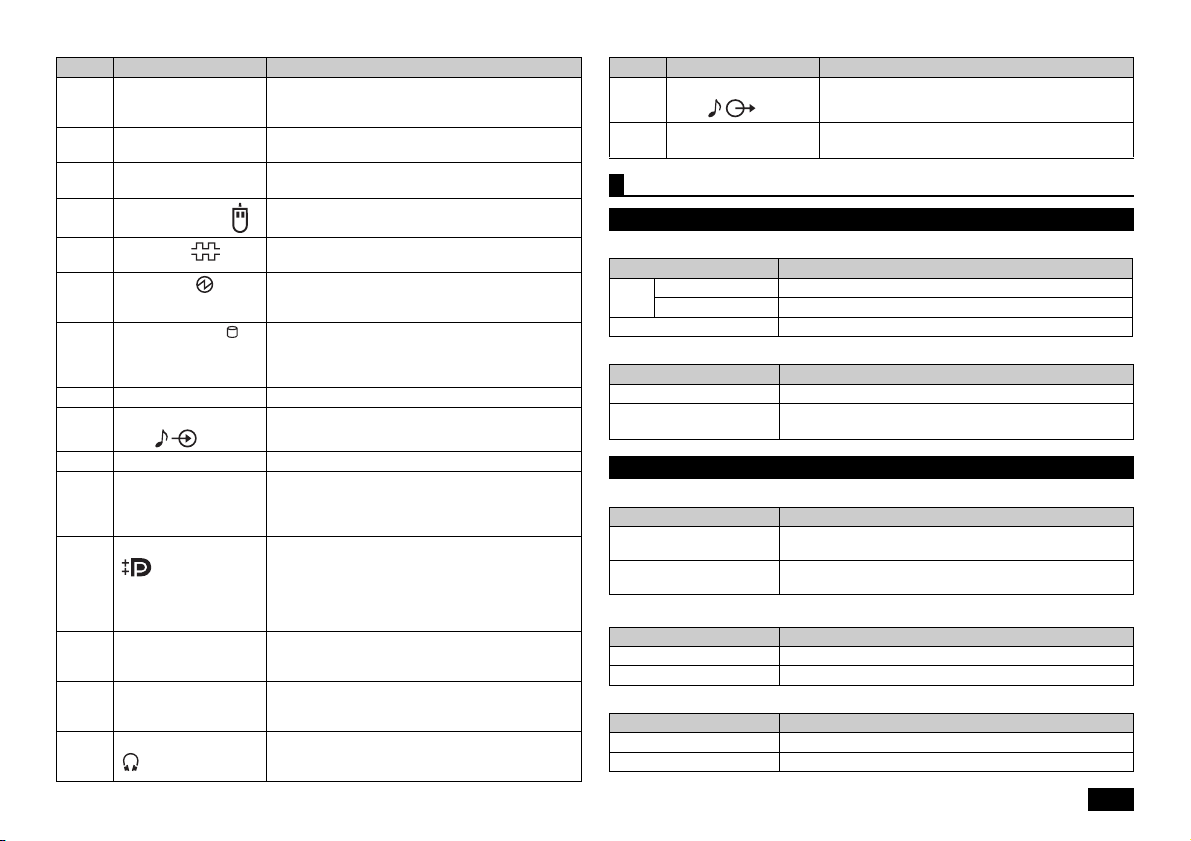
Number Name Explanation
(9) Air vent These holes are designed to allow internal heat to
(10) Chassis lock A security cable (sold separately) can be attached
(11) AC power input jack A jack used to supply power to the machine.
(12)
PS/2 mouse port ( )
(13)
Serial port ( )
(14)
Power LED ( )
(15)
Drive activity LED ( )
(16) Stand This keeps the computer stable.
(17) Line input terminal (mini
jack) ( )
(18) Setscrews Fixes the computer side cover.
(19) Cable stopper Prevents the keyboard cable from pulling out or
(20) DisplayPort connector
()
(21) PCI slot A slot used to attach a PCI board.
(22)
PCI Express x1 slot
(23) Headphone jack
()
escape.
Please be careful not to leave the air vent blocked.
to this slot.
Connects to the supplied power cord.
A port used to connect a PS/2 (MiniDIN 6-Pin)
mouse.
This is used to connect to devices that have a
serial port.
It indicates the power status. This indicator
continues to light when the power is on, and it
flashes in the Sleep mode.
This indicator lights up when accessing the hard
disk or the optical drive.
Do not press the power switch when the Drive activity
LED is lit. It may cause damage to the hard disk.
A terminal used to input audio signals from audio
devices.
protects devices connected using cables against
theft. The cable stopper can be found in the
included accessory case.
The computer can be connected to a display that
has a DVI-D interface, using the DisplayPort to
DVI-D adapter.
The operation is only checked at this port when
the display is connected via the DisplayPort to
DVI-D adapter.
Helps to enhance and extend the machine's
functions.
A slot used to attach a PCI Express x1 board.
Helps to enhance and extend the machine's
functions.
The port to connect a stereo headphone that has a
mini plug. Do not plug in/unplug the headphone to/
from the jack when you are using the headphone.
Number Name Explanation
(24) Line out terminal (mini
jack) ( )
(25) PCI Express x16 slot A slot used to attach a PCI Express x16 board.
A terminal used to output audio signals to audio
devices.
Helps to enhance and extend the machine's functions.
Status LEDs
Base unit
Power LED
LED state Computer State
On Computer power on
Green
Flashing Sleep
Off Computer power off, or hibernating
Drive activity LED
LED state Computer State
On (Green) The hard disk or optical drive is currently accessing data.
Off The hard disk or optical drive is not currently accessing
Keyboard
Caps lock indicator LED
LED state Computer State
On (Green) <Caps Lock> is on (all letters are entered as capital
Off <Caps Lock> is off (all letters are entered as lowercase
Scroll Lock indicator LED
LED state Computer State
On (Green) <Scroll Lock> is on
Off <Scroll Lock> is off
Num Lock indicator LED
LED state Computer State
On (Green) <Num Lock> is on
Off <Num Lock> is off
data.
letters))
letters))
7
Mouse
5
6
LAN Function
A USB mouse is included.
A sensor detects the movement of the mouse with the assistance of the light source at
the bottom of the mouse. In the following cases the mouse may not move properly
(the mouse pointer may respond as you expect).
• Reflective surfaces (mirrors or glass)
• Surfaces with continuous patterns like halftone printings (such as magazines and
images in newspapers)
• Striped surfaces or patterns with strong shading
• Shiny surfaces including transparent and translucent materials
Using the scroll wheel
Scroll wheel features are only available when using the applications that support them.
• Vertical scrolling
You can scroll up and down by rotating the wheel back and forth.
• Auto scrolling
A scroll icon is displayed when you click or hold down the wheel.
When the icon is displayed, you can scroll up and down by moving the mouse in
the direction of the arrows.
By clicking the wheel again or realizing your finger, the scroll icon disappears.
This section covers important points and the correct procedure for setting up the LAN
(Local Area Network) function.
LAN settings
The following provides a simple explanation about how to perform network setup in
order to connect to a LAN.
Setting up a network connection
Network connection settings can be changed by going to the [Control Panel] and
clicking [Network and Internet] [View network status and tasks] [Change
adapter settings].
For more detailed information, please refer to Windows help.
The following step allows you to change settings such as the computer name.
Setting the computer name and network to connect to
You can change settings related to the connected network and change the name of
your computer as it is displayed on the network by opening the [Control Panel] and
clicking [System and Security] [System], and then selecting [Change settings]
under [Computer name, domain, and workgroup settings].
For more detailed information, please refer to Windows help.
This is all you need to do to correctly setup your LAN.
Remote power on (WoL - Wake on LAN)
Remote Power On (WoL - Wake on LAN) allows you to do the following.
• Remotely turn your computer on after the power is off.
• Remotely wake up your computer after sleep or hibernate.
If you configure your computer to allow WoL, the LAN adapter stays active, even
when the computer power is off.
A special packet (Magic Packet) that instructs your computer to turn on can be
transmitted from a remote administrator's PC. When this packet is received by the
computer's dedicated controller, it triggers the power to be turned on.
This allows you to be able to remotely turn your computer's power on or wake it up
from sleep or hibernate from an administrator's PC when your computer has a LAN
connection.
8

• In order to enable WoL, it is necessary to install special software on the
administrator's PC to allow sending of Magic Packets.
• When using the WoL, disable the "Fast Startup" function. For more detailed
information, please refer to "Disabling the "Fast Startup" function" (p.23 ).
• It is not possible to use WoL in cases where the previous system shutdown (power
off, sleep, or hibernate) was not correctly completed. If this is the case, please turn
the power back on, restart Windows, and once again perform a system shutdown
using the correct procedure.
• WoL cannot be used with a hub that only supports a speed of 1000 Mbps. Please
use a hub that supports 10M/100M/1000M Auto-negotiation.
Network booting function (PXE)
This enables booting via a network, and remote connection to your computer
from an administrator's PC which allows you to do the following.
• Operating system installation
• BIOS flashing (Rewriting the BIOS ROM)
• BIOS configuration changes
As this computer has the UEFI function, it is necessary to change the network boot
server to use the UEFI.
How to configure your computer to allow WoL from when the power is turned off
The following steps can be used to configure your computer to allow WoL from when
the power is turned off.
1 Turn on the power and immediately press <F2> several times.
The BIOS setup utility will then be displayed.
2 From the [Power] menu, call the [Automatic Power On] menu, and set the
[Wake on LAN] option to either [Primary] or [Automatic].
Select [Startup] from the Menu bar. Then, select [Primary Boot Sequence] or
[Automatic Boot Sequence] and set the startup device according to your operating
environment.
3 Press the <F10> key.
4 Confirm that [Yes] is selected and then press <Enter>.
These setting values are saved, the BIOS setup utility will finish, and your
computer will restart.
Configuration is now complete.
How to configure your computer to allow WoL from sleep or hibernate mode
Specify the following settings in [Device Manager] -> [Network adapters].
Double click [Network adapters], and double click the displayed LAN adapter.
Check the following items in the [Power Management] tab.
• [Allow the computer to turn off this device to save power.]
• [Allow this device to wake the computer.]
• [Only allow a magic packet to wake the computer.]
Setup is now complete.
Configuring the BIOS setup utility to enable network booting.
1 Turn the power on and immediately press <F2> key several times.
The BIOS setup utility will then be displayed.
2 From the [Devices] menu, call the [Network Setup] menu and then set the
[Boot Agent] to [PXE]. Also, set the [PXE IPV4 network stack] or [PXE IPV6
network stack] to [Enabled].
3 Press the <F10> key.
A confirmation screen should be displayed.
4 Confirm that [Yes] is selected and then press <Enter>.
These setting values are saved, the BIOS setup utility will finish, and your
computer will restart.
5 Immediately press the <F2> key several times.
The BIOS setup utility will then be displayed.
6 From the [Startup] menu, call the [Primary Boot Sequence] menu, select
[Network 1], and set it to the highest level by pressing the <+> key.
7 Press the <F10> key.
8 Confirm that [Yes] is selected and then press <Enter>.
These setting values are saved, the BIOS setup utility will finish, and your
computer will restart.
This is all you need to do to correctly setup network booting.
9
 Loading...