


Value and Comprehensive Manageability
P
OWER
M
ATE®
ES 5250 S
ERIES
SERVICE AND REFERENCE
MANUAL ADDENDUM

Proprietary Notice and Liability Disclaimer
The information disclosed in this document, including all designs and related materials, is the
valuable property of NEC Computer Systems Division, Packard Bell NEC, Inc. (hereinafter “NEC
CSD”) and/or its licensors. NEC CSD and/or its licensors, as appropriate, reserve all patent,
copyright and other proprietary rights to this document, including all design, manufacturing,
reproduction, use, and sales rights thereto, except to the extent said rights are expressly granted to
others.
The NEC CSD product(s) discussed in this document are warranted in accordance with the terms of
the Warranty Statement accompanying each product. However, actual performance of each such
product is dependent upon factors such as system configuration, customer data, and operator
control. Since implementation by customers of each product may vary, the suitability of specific
product configurations and applications must be determined by the customer and is not warranted
by NEC CSD.
To allow for design and specification improvements, the information in this document is subject to
change at any time, without notice. Reproduction of this document or portions thereof without prior
written approval of NEC CSD is prohibited.
NEC and PowerMate are registered trademarks of NEC Corporation, used under license.
All other product, brand, or trade names used in this publication are the trademarks or registered trademarks of their
respective trademark owners.
First Printing — October 1999
Copyright 1999
NEC Computer Systems Division
6000 Florin-Perkins Road
Sacramento, CA 95828-1037
All Rights Reserved

Contents
Preface................................................................................................................................. vii
1 System Overview
System Board..................................................................................................................... 1-2
ATI 3D RAGE XL Graphics Accelerator..................................................................... 1-2
Network Support........................................................................................................... 1-3
SCSI Adapter Board...........................................................................................................1-4
EIDE and SCSI Hard Drives.............................................................................................. 1-4
2 System Boards and Hard Drives
System Board Jumpers....................................................................................................... 2-2
Checking Power On Mode Jumper JP1........................................................................ 2-3
Setting CMOS Clear Jumper JBAT1............................................................................ 2-4
Setting Onboard Video Jumper JVGA1.......................................................................2-4
Setting CPU Bus Frequency Selector Jumper JK1....................................................... 2-4
Setting AGP Bus Frequency Selector Jumper JK2....................................................... 2-5
SCSI Adapter Board Connectors and Jumpers .................................................................. 2-5
SCSI Hard Drive Connectors and Jumpers........................................................................ 2-6
3 Illustrated Parts Breakdown
Parts and Options...............................................................................................................3-2
Documentation and Packaging...........................................................................................3-3
Field Replaceable Unit List — Small Desktop.................................................................. 3-3
Illustrated Parts Breakdown (IPB) — Small Desktop........................................................3-6
Field Replaceable Unit List — Desktop............................................................................ 3-7
Illustrated Parts Breakdown (IPB) — Desktop................................................................ 3-10
Field Replaceable Unit List — Minitower....................................................................... 3-11
Illustrated Parts Breakdown (IPB) — Minitower ............................................................ 3-14
A PowerMate ES 5250 Series Release Notes
Applications and Online Documentation.......................................................................... A-2
Installing Applications in the Correct Order................................................................ A-2
Installing NEC SNMP Agent....................................................................................... A-3
Uninstalling the NEC SNMP Agent or LANDesk Client Manager............................. A-4
When Both NEC SNMP Agent and LANDesk Client Manager Are Installed... A-4
When LANDesk Client Manager Is Installed Without the NEC SNMP Agent.. A-4
Installing Cheyenne Backup........................................................................................ A-5
Installing PartitionMagic ............................................................................................. A-5
Installing Internet Explorer 4.01 Add-On Components............................................... A-5
Using the LS-120 SuperDisk Copy Utility.................................................................. A-6
System Configuration....................................................................................................... A-6
Configuring the System for the NEC SNMP Agent.................................................... A-6
Configuring the System for NEC WebTelligent.......................................................... A-6
Configuring the System for Microsoft Internet Explorer............................................. A-7
Changing Network Settings......................................................................................... A-7
Contents iii

Checking Differences Between CMOS Setup Defaults and Shipped Settings ............A-8
From the Standard CMOS Setup Menu.............................................................. A-8
From the PNP/PCI Configuration Menu............................................................ A-8
From the Integrated Peripherals Menu............................................................... A-8
Identifying the Pentium III Processor ..........................................................................A-9
Setting Boot Order in BIOS.........................................................................................A-9
Getting CD-ROM Support in Command Prompt Only Mode ...................................A-10
SCSI Drive Limitations...................................................................................................A-10
Booting from a CD.....................................................................................................A-10
Using the NEC OS Restore CD with a SCSI Drive...................................................A-10
Intel Processor Serial Number Control Utility................................................................A-10
Identifying System Requirements..............................................................................A-11
Installing the Utility...................................................................................................A-11
Looking at Serial Number Features ...........................................................................A-11
Getting Answers to FAQs..........................................................................................A-11
Getting Intel Technical Support.................................................................................A-13
Windows 95 Issues..........................................................................................................A-13
Controlling CD Audio................................................................................................A-13
Using Cheyenne Backup............................................................................................A-13
Backing Up Large Drives................................................................................... A-13
Using Cheyenne Backup with LANDesk Client Manager................................. A-13
Using Cheyenne Backup with the Seagate Travan Tape Backup.......................A-14
Clicking the Product Catalog Button .........................................................................A-14
Restoring Software with a U.S. Robotics 56K V.90 Modem Installed......................A-14
Configuring the System for PIIX4 Support................................................................A-14
Reconfiguring Ultra DMA Support.................................................................... A-14
Determining IDE Device Compatibility............................................................. A-15
Windows 98 Issues..........................................................................................................A-15
Ejecting the NE C Applicat io n a n d D r iver CD f ro m a DVD-ROM Driv e....................A-15
Finding Tape Device Icons ........................................................................................A-15
Installing CD-ROM MS-DOS Drivers on Systems with
Windows 98 Second Edition..................................................................................A-15
Windows NT Issues.........................................................................................................A-16
Installing TCP/IP Protocol.........................................................................................A-16
Restoring Network Card Drivers................................................................................A-16
Installing BootMagic in a System with Windows NT ...............................................A-17
Configuring BootMagic ..................................................................................... A-17
Correcting the BootMagic Configuration........................................................... A-18
Regulatory Statements
iv Contents

List of Figures
PowerMate ES 5250 Series Small Desktop IPB....................................................................................... 3-6
PowerMate ES 5250 Series Desktop IPB............................................................................................... 3-10
PowerMate ES 5250 Series Minitower IPB............................................................................................3-14
List of Tables
Locating System Board Jumpers.............................................................................................................. 2-3
Power On Mode Jumper JP1 Settings....................................................................................................... 2-3
CMOS Clear Jumper JBAT1 Settings ...................................................................................................... 2-4
Onboard Video Jumper JVGA1 Settings.................................................................................................. 2-4
CPU Bus Frequency Selector Jumper JK1 Settings..................................................................................2-4
AGP Bus Frequency Selector Jumper JK2 Settings ................................................................................. 2-5
Ordering Parts and Options.......................................................................................................................3-2
PowerMate ES 5250 Series Documentation and Packaging..................................................................... 3-3
PowerMate ES 5250 Series FRU List — Small Desktop ......................................................................... 3-3
PowerMate ES 5250 Series FRU List — Desktop ................................................................................... 3-7
PowerMate ES 5250 Series FRU List — Minitower.............................................................................. 3-11
Contents v

Preface
This addendum contains technical information for the NEC PowerMate
ES 5250 Series of small desktop, desktop, and minitower computers. It provides
technical information for system components unique to the PowerMate ES 5250
Series computers.
The addendum is a supplement to the NEC PowerMate ES 5200 Series Service
and Reference Manual (NEC part number 456-00043-000SRV).
The addendum is organized as follows.
Section 1, System Overview, provides an overview of the unique components
of the PowerMate ES 5250 series, including an enhanced system board, Intel
Pentium® III 600-MHz processor, SCSI adapter board, and IDE and SCSI hard
drives.
Section 2, System Boards and Hard Drives, provides connector, switch, and
jumper setting information for the system board, SCSI adapter board, and hard
drives.
Section 3, Illustrated Parts Breakdown, includes an illustrated parts
breakdown diagram and parts list for the PowerMate ES 5250 Series computers.
Appendix A, NEC PowerMate ES 5250 Series Release Notes, describes
recommended operating procedures and technical data not documented in other
PowerMate ES 5250 Series documentation.
®
®
Preface vii

System Overview
System Board
!
SCSI Adapter Board
!
EIDE and SCSI Hard Drives
!
1

This section provides an overview of the NEC PowerMate ES 5250® Series
computer, an enhanced version of the PowerMate ES 5200 Series computer.
Included in this section are descriptions of components that differ from those in
the NEC PowerMate ES 5200 Series. Also included is an overview of several
build-to-order options available for the PowerMate ES 5250 Series of
computers.
Hardware and technical information that is common between the PowerMate ES
5250 series and the PowerMate ES 5200 series is not included in this addendum.
The reader should refer to the NEC PowerMate ES 5200 Series Service and
Reference Manual for common component information.
Externally, the front and back of the PowerMate ES 5250 series do not differ
from the PowerMate ES 5200 series. Internally, the PowerMate ES 5250 uses an
enhanced Micro-Star MS-6131 (rev 3.0C) system board with onboard
ATI® 3D RAGE XL™ graphics accelerator chip
!
8 MB of video memory
!
Intel® 82559 10/100 Ethernet network chip
!
support for a Pentium® III 600-MHz processor with 100-MHz front side
!
bus (FSB).
Additionally, support is included for an Adaptec® 2940 Ultra2 Wide SCSI
adapter board and high capacity Enhanced IDE (EIDE) and small computer
system interface (SCSI) 7200 rpm hard drives.
See the following sections for additional information on the system board, SCSI
adapter board, and hard drives.
System Board
The Micro-Star MS-6131 Rev. 3.0C NLX system board supports Intel Celeron
processors (up to 433 MHz), Pentium II processors (up to 450 MHz), and
Pentium III processors (up to 600 MHz). The board uses the same Intel
82440BX PCI chipset, system memory, audio controller, clock, I/O controller,
battery, and hardware monitor as the system boards used in the PowerMate ES
5200 Series.
Enhancements to the board include the addition of the ATI
graphics accelerator chip, 8 MB of video memory, Intel 82559 10/100 Ethernet
network chip, and support for the Pentium III 600-MHz processor and 7200 rpm
EIDE and SCSI hard drives.
ATI 3D RAGE XL Graphics Accelerator
®
3D RAGE XL
®
™
The ATI 3D Rage XL graphics accelerator chip on the system board provides
high quality full accelerated graphics port (AGP) 2X acceleration and 2D, 3D,
and video acceleration.
1-2 System Overview

For 3D acceleration, the chip features an integrated 1.2 million triangles/second
set-up engine that reduces CPU use and bus bandwidth requirements. For 2D
acceleration, the chip features hardware acceleration of Bitbit and Line Draw.
Motion video acceleration features include hardware DVD decode through
Motion Compensation and Inverse Discrete Cosign Transformation to provide
full frame rate playback of DVD content.
Included on the chip is a 4KB texture cache and support for Gouraud shading
and Direct 3D texture lighting.
The chip is supported with 8 MB of video SGRAM installed on the system
board.
Network Support
The system board has an Intel 82559 10BASE-T/100BASE-TX network
controller chip and an external LAN connector at the back of the system. The
chip combines small size and low power consumption to deliver highly
manageable fast ethernet connectivity.
Features of the 82559 controller include:
Advanced Configuration and Power Interface (ACPI)
!
wake on Magic Packet
!
wake on interesting packet
!
advanced System Management Bus (SMS)
!
Wired for Management (WfM) support
!
IP checksum assist
!
PCI 2.2 compliance
!
PC 98 and PC 99 compliance
!
full duplex support at both 10 and 100 Mbps
!
Wake on LAN
!
low power 3.3V device.
!
™
The chip also has Alert on LAN™ , a technology that alerts system
administrators when a system has a problem.
System Overview 1-3

SCSI Adapter Board
Some systems may come with the Adaptec 2940 Ultra2 Wide SCSI board
installed in a PCI expansion slot. The SCSI adapter board brings the highest
performance SCSI I/O technology to the PCI local bus, transferring data up to a
maximum rate of 80 MB/second (up to a 133 MB host bus burst data rate). The
adapter board is compatible with all device protocols, including SCSI-1,
SCSI-2, Ultra SCSI, and Ultra2 SCSI.
For systems with the SCSI adapter board, the Adaptec SCSISelect configuration
utility comes installed on the system. The utility can be used to configure the
adapter board. The utility eliminates the need to use jumpers or terminators
when adding SCSI peripherals.
For systems with the adapter board and SCSI hard drive, a four-connector SCSI
cable is used to connect the drive to the adapter board. With this configuration,
up to four SCSI devices can be connected, including the factory installed
adapter board and SCSI hard drive. By purchasing additional SCSI interface
cables, up to a total of fifteen SCSI peripherals can be connected to the adapter
board.
Additional information on the SCSI adapter board is given in Section 2 of this
addendum.
EIDE and SCSI Hard Drives
All systems ship with a 3 1/2-inch hard drive, either EIDE or SCSI. Systems
might come with one of the following drives:
4.3-GB Ultra DMA 33, 5400 rpm
!
8.4-GB Ultra DMA 33, 5400 rpm
!
12.9-GB Ultra DMA 33, 5400 rpm
!
12.8-GB Ultra DMA 33, 7200 rpm
!
17-GB Ultra DMA 33, 7200 rpm
!
20-GB Ultra DMA 33, 7200 rpm
!
9.1-GB SCSI Ultra Wide, 7200 rpm
!
18-GB SCSI Ultra Wide, 7200 rpm.
!
Further information on the SCSI hard drives is included in Section 2 of this
addendum. Information on the EIDE hard drives is included in the PowerMate
ES 5200 Series Service and Reference Guide.
1-4 System Overview

2
System Boards and Hard Drives
System Board
!
SCSI Adapter Board
!
SCSI Hard Drive
!

This section contains the connector, switch, and jumper setting information for
the following components of the PowerMate ES 5250 Series computers:
system board
!
SCSI adapter board
!
9.1-GB 7200 rpm Wide Ultra SCSI hard drive
!
18-GB 7200 rpm Wide Ultra SCSI hard drive.
!
For information on common components in the PowerMate ES 5250 Series of
computers, refer to the PowerMate ES 5200 Series Service and Reference
Manual.
System Board Jumpers
System board jumpers set system configuration for a particular requirement. The
system board has the following jumpers (jumper locations are shown in the
following figure).
Jumpers are set correctly at the factory for the system
configuration. Only change the appropriate jumper settings.
Otherwise, keep the jumpers at their factory settings.
Power On Jumper JP1 — sets the way the system starts up (jumper
!
correctly set at factory, do not change the factory setting).
CMOS Jumper JBAT1 — clears CMOS and resets the settings back to
!
their factory state.
VGA Mode Jumper JVGA1 — disables onboard video if adding a video
!
board to the system.
Note
:
The location of jumper JVGA1 on the PowerMate
ES 5250 system board (see the following figure) differs from
the location of jumper JVGA1 on the PowerMate ES 5200
system board.
CPU Bus Frequency Selector Jumper JK1 — selects 66-MHz or
!
100-MHz CPU bus frequency.
AGP Bus Frequency Selector Jumper JK2 — selects AGP bus frequency
!
or PCI bus frequency.
Jumper settings are described in the following paragraphs. For detailed
procedures on changing a system board jumper setting, refer to the PowerMate
ES 5200 Series Service and Reference Manual.
2-2 System Boards
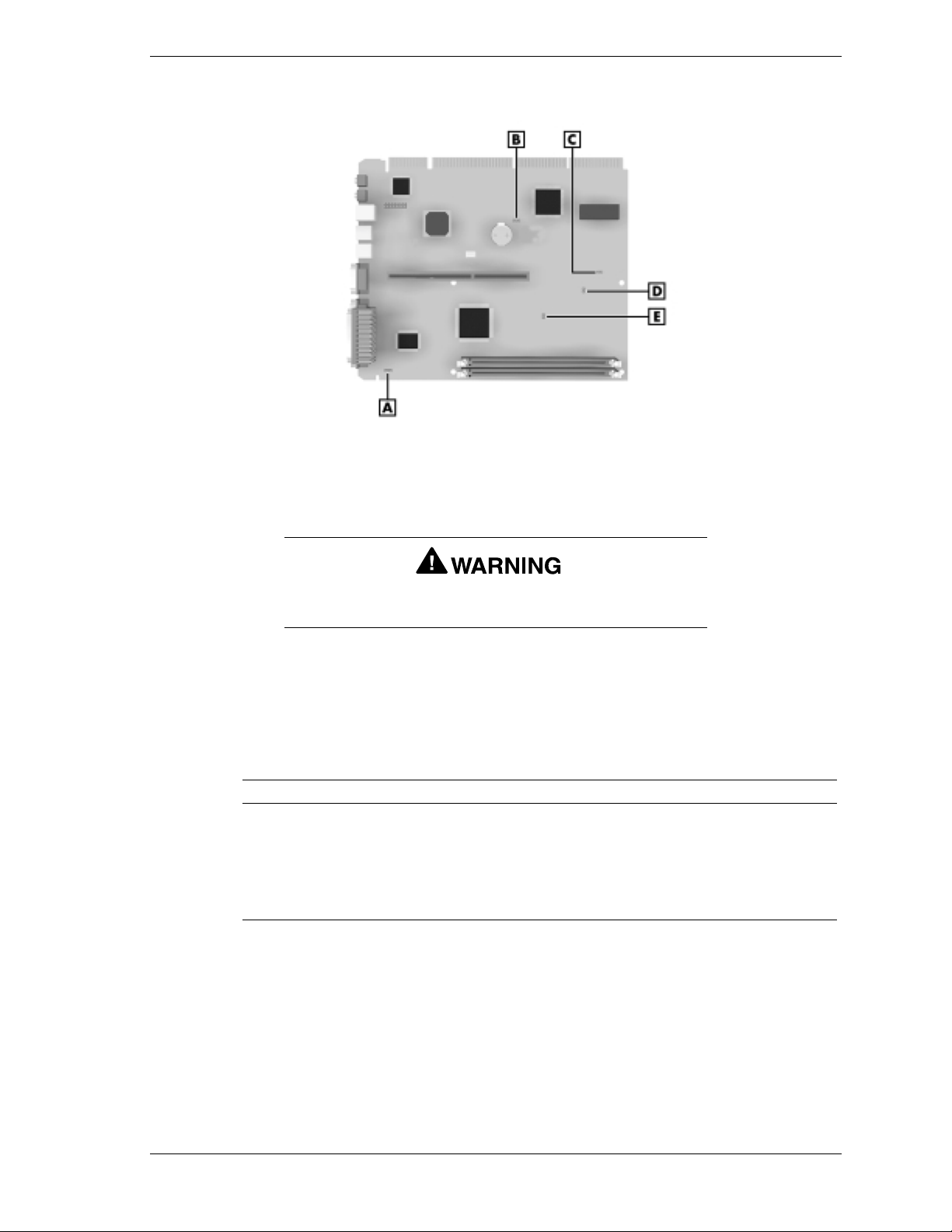
Locating System Board Jumpers
A
– VGA Mode Jumper JVGA1
B
– CMOS Clear Jumper JBAT1
C
– Power On Mode Jumper JP1
D
– CPU Bus Frequency Selector Jumper JK1
E
– AGP Bus Frequency Selector Jumper JK2
The system power must be off before opening the system
and changing a jumper setting.
Checking Power On Mode Jumper JP1
The Power On Mode JP1 jumper setting are shown in the following table. Keep
the jumper setting in the open setting (pins 1 and 2, no jumper).
Power On Mode Jumper JP1 Settings
JP1 Pins Function
1-2 Not Jumpered Factory setting — no jumper, do not change. This
setting conforms to BIOS setting for “Restore
AC/Power Loss” in Power Management section of
CMOS Setup Menu.
2-3 Do not use this jumper setting.
System Boards 2-3

Setting CMOS Clear Jumper JBAT1
If the CMOS needs to be cleared and reset back to the factory settings, move the
jumper from pins 1 and 2 to 2 and 3 on jumper block JBAT1 (see the following
table for settings). After approximately five seconds, move the jumper back to
pins 1 and 2 to keep any future CMOS changes.
CMOS Clear Jumper JBAT1 Settings
JBAT1 Pins Function
1-2 Jumpered Factory setting. Keeps CMOS changes.
2-3 Jumpered Clears CMOS changes.
Setting Onboard Video Jumper JVGA1
If adding a video board to the system, the onboard video must be disabled by
moving the jumper from pins 1 and 2 to pins 2 and 3 on jumper block JVGA1
(see the following table for settings).
Onboard Video Jumper JVGA1 Settings
JVGA1 Pins Function
1-2 Jumpered Factory setting. Enables onboard video.
2-3 Jumpered Disables onboard video.
Setting CPU Bus Frequency Selector Jumper JK1
Enables automatic detection of the CPU bus frequency (66 MHz or 100 MHz)
when pins 1 and 2 are jumpered on jumper block JK1. When the jumper is
removed from JK1, the system automatically sets the CPU bus frequency to
100 MHz (see the following table for settings).
CPU Bus Frequency Selector Jumper JK1 Settings
JK1 Pins Function
1-2 Jumpered Factory setting. Enables auto detection of 66-MHz
and 100-MHz frequencies.
1-2 Not Jumpered Sets CPU bus frequency to 100 MHz.
2-4 System Boards

Setting AGP Bus Frequency Selector Jumper JK2
The AGP bus frequency selector jumper JK2 sets the AGP bus frequency to
66 MHz when pins 1 and 2 are jumpered. Removing the jumper from pins 1 and
2 sets the AGP bus to the PCI bus frequency (see the following table for
settings).
AGP Bus Frequency Selector Jumper JK2 Settings
JK2 Pins Function
1-2 Jumpered Factory setting. Sets the AGP bus frequency to 66
MHz.
1-2 Not Jumpered
Sets the AGP bus frequency to the PCI bus
frequency.
SCSI Adapter Board Connectors and Jumpers
The build-to-order Adaptec 2940U2W Ultra2 Wide SCSI adapter board is
installed in one of the PCI expansion board slots in the system.
The board has four connectors:
68-pin high density Ultra2 Wide SCSI internal connector
!
68-pin high-density Ultra2 Wide SCSI external connector
!
68-pin high density Ultra Wide SCSI internal connector
!
50-pin high density Ultra SCSI internal connector.
!
For systems with the SCSI adapter board and SCSI hard drive, one end of the
factory installed SCSI interface ribbon cable connects to the 68-pin high density
Ultra2 Wide SCSI internal connector on the SCSI board. The other end connects
to the internal SCSI hard drive.
The SCSI adapter board has no switches or jumpers to set. The SCSI IDs and
terminations are normally set by jumpers on the SCSI hard drive (see “Hard
Drive Connectors and Jumper Settings” in this section). Settings can also be set
through the factory installed Adaptec SCSISelect™ software. All SCSI settings
are preset at the factory, including SCSI IDs and terminations.
All SCSI adapter board software settings are correctly set at
the factory for the system configuration. Do not change the
settings. Doing so may disable the adapter boar d , har d
drive, or both.
System Boards 2-5

You can view the SCSI settings or reconfigure the SCSI adapter board through
™
the factory installed Adaptec SCSISelect
during system startup by pressing the
software. The software is accessed
and
Ctrl
A
keys when the following
message appears on the screen:
Press <Ctrl><A> for SCSISelect(TM) Utility!
For further information on the SCSI adapter board, refer to the Adaptec SCSI
documentation.
SCSI Hard Drive Connectors and Jumpers
A typical SCSI hard drive installed in the system has a 68-pin connector for
attaching the SCSI interface cable. The other end of the cable attaches to the
internal 68-pin connector on the SCSI adapter board.
The drive must have a unique address (ID), which is set through jumper blocks
on the hard drive. Additional jumpers set the drive’s termination and other
required functions.
Hard drive jumpers are correctly set at the factory for
optimum operation. Do not reset the jumpers. Doing so may
disable the hard drive, adapter board, or both.
For further information on the SCSI hard drive, including jumper information,
refer to the hard drive documentation.
2-6 System Boards

Illustrated Parts Breakdown
Parts and Options
!
Documentation and Packaging
!
Field Replaceable Unit List — Small Desktop
!
Illustrated Parts Breakdown — Small Desktop
!
Field Replaceable Unit List — Desktop
!
Illustrated Parts Breakdown — Desktop
!
Field Replaceable Unit List — Minitower
!
Illustrated Parts Breakdown — Minitower
!
3

This section contains the NEC CSD part lists and illustrated parts breakdowns
(IPB) for the PowerMate ES 5250 Series build-to-order small desktop, desktop,
and minitower systems.
The following sections provide
telephone numbers for ordering system parts and options
!
list of documentation and packaging for the system
!
lists of field-replaceable parts for each system
!
an illustrated parts breakdown figure for each system.
!
Parts and Options
The following table lists the telephone numbers to use when ordering spare parts
and options.
Ordering Parts and Options
Items Telephone Number
To order spare parts (Dealers) 1-800-632-4525
To order spare parts (Customers) In the U.S. 1-800-233-6321
In Canada 1-800-727-2787
3-2 Illustrated Parts Breakdown

Documentation and Packaging
The following documentation and packaging may be ordered from NEC CSD
(depending on availability).
PowerMate ES 5250 Series Documentation and Packaging
Description
User’s Guide, PowerMate ES 5250 Series
Shipping carton, small desktop
Shipping carton, desktop
Shipping carton, minitower
NEC OS Restore CD – WIN 95
NEC OS Restore CD – WIN 98
NEC OS Restore CD – NT 4.0
NEC Application and Driver CD – WIN 95
NEC Application and Driver CD – WIN 98
NEC Application and Driver CD – NT 4.0
The following documentation is available online at the NEC CSD website
(www.nec-computers.com/):
PowerMate ES 5200 Series Service and Reference Manual
!
PowerMate ES 5250 Addendum to PowerMate ES 5200 Series Service
!
and Reference Manual.
Field Replaceable Unit List — Small Desktop
The following table lists the field replaceable units (FRU) for the PowerMate
ES 5250 Series small desktop computers. See “Illustrated Parts Breakdown
(IPB) — Small Desktop” for a figure showing an exploded view of these parts.
PowerMate ES 5250 Series FRU List — Small Desktop
Item Description
1 Microsoft IntelliMouse
2 Keyboard, Chicony
3 Power cable
4 IDE cable, 3-connector
5 Diskette drive signal cable
6 CD-ROM audio cable
Illustrated Parts Breakdown 3-3

PowerMate ES 5250 Series FRU List — Small Desktop
Item Description
7 Wake-ON LAN cable
8 Chassis intrusion switch and cable assembly
9 RJ-11 cable
10 System board guide rails (2)
11 System board latch (1)
12a
12b
12c
12d
13a
13b
13c
14 Retaining arm (for Celeron and Pentium III processors)
15a
15b
15c
16a
16b
16c
16d
16e
16f
16g
16h
16i
17 Battery
18 PowerMate ES 5250 Series system board (Intel 440BX) with onboard audio, ATI Rage XL
32-MB SDRAM, DIMM
64-MB SDRAM, DIMM
128-MB SDRAM, DIMM
256-MB SDRAM, DIMM
Retention mechanism (for Celeron processors)
Retention mechanism (for Pentium II processors)
Retention mechanism (for Pentium III processors)
Heat sink (for Celeron processors)
Heat sink (for Pentium II processors)
Heat sink (for Pentium III processors)
300-MHz Celeron processor
333A-MHz Celeron processor
366A-MHz Celeron processor
350-MHz Pentium II processor
400-MHz Pentium II processor
450-MHz Pentium II processor
450-MHz Pentium III processor
500-MHz Pentium III processor
600-MHz Pentium III processor
graphics, 8-MB video memory, Intel 82559 LAN chip, 600-MHz processor support
19 I/O plate
20 Riser card
21 Rear USB connector and cable assembly
®
22 Sound card, Creative Labs Sound Blaster
23a
23b
24 3Com 10/100 Hurricane Ethernet network card with Wake-ON LAN
25 Chassis cover, small deskto p
26 Speakers, Harman Kardon 10 watt
27 Speaker AC adapter, Harman Kardon
28 Power supply, 145 watt
29 Internal hard drive bracket
56 Kbps Fax/modem US Robotics V.90 Python ISA board
56 Kbps MDM100 Winmodem PCI board
Live!™ PCI
3-4 Illustrated Parts Breakdown

PowerMate ES 5250 Series FRU List — Small Desktop
Item Description
30a
30b
30c
30d
30e
30f
30g
30h
31 Diskette drive, w/o bezel
32a
32b
32c
33 DVD-ROM
34 LS-120 cradle
35 LS-120 drive
36 Logo, “NEC PowerMate”
37 Front panel
38 Front panel PCB switch (includes Power and Sleep)
39 Fan assembly
40 Front USB port board and cable assembly
4.3-GB IDE 5400 rpm hard drive
8.4-GB IDE 5400 rpm hard drive
12.9-GB IDE 5400 rpm hard drive
12.8-GB IDE 7200 rpm hard drive
17-GB IDE 7200 rpm hard drive
20-GB IDE 7200 rpm hard drive
9.1-GB Ultra Wide SCSI 7200 rpm hard drive
18.0-GB Ultra Wide SCSI 7200 rpm hard drive
32X IDE CD-ROM, Lite-On
32X IDE CD-ROM, NEC
40X IDE CD-ROM, Lite-On
not shown SCSI adapter board
not shown SCSI interface cable, 4-connector
not shown Headset w/microphone
not shown Tape cartridge
not shown Zip disk
not shown LS-120 diskette
Illustrated Parts Breakdown 3-5

Illustrated Parts Breakdown (IPB) — Small Desktop
The following figure shows the illustrated parts breakdown (IPB) for
PowerMate ES 5250 Series small desktop computers. Each item in the IPB is
identified with a number that cross-references to the small desktop FRU list.
PowerMate ES 5250 Series Small Desktop IPB
3-6 Illustrated Parts Breakdown

Field Replaceable Unit List — Desktop
The following table lists the field replaceable units (FRU) for
PowerMate ES 5250 Series desktop computers. See “Illustrated Parts
Breakdown (IPB) — Desktop” for a figure showing an exploded view of these
parts.
PowerMate ES 5250 Series FRU List — Desktop
Item Description
1 Microsoft IntelliMouse
2 Keyboard, Chicony
3 Power cable
4 IDE cable, 3-connector
5 Diskette drive signal cable
6 PCMCIA cable, 2-connector
7 CD-ROM audio cable
8 Wake-ON LAN cable
9 RJ-11 cable
10 System board guide rails (2)
11 System board latches (2)
12a
12b
12c
12d
13a
13b
13c
14 Retaining arm (for Celeron and Pentium III processors)
15a
15b
15c
16a
16b
16c
16d
16e
16f
16g
16h
16i
17 Battery
32-MB SDRAM, DIMM
64-MB SDRAM, DIMM
128-MB SDRAM, DIMM
256-MB SDRAM, DIMM
Retention mechanism (for Celeron processors)
Retention mechanism (for Pentium II processors)
Retention mechanism (for Pentium III processors)
Heat sink (for Celeron processors)
Heat sink (for Pentium II processors)
Heat sink (for Pentium III processors)
300-MHz Celeron processor
333A-MHz Celeron processor
366A-MHz Celeron processor
350-MHz Pentium II processor
400-MHz Pentium II processor
450-MHz Pentium II processor
450-MHz Pentium III processor
500-MHz Pentium III processor
600-MHz Pentium III processor
18 PowerMate ES 5250 Series system board (Intel 440BX) with onboard audio, ATI Rage XL
graphics, 8-MB video memory, Intel 82559 LAN chip, 600-MHz processor support
19 I/O plate
Illustrated Parts Breakdown 3-7

PowerMate ES 5250 Series FRU List — Desktop
Item Description
20 Riser card
21 Chassis intrusion switch
22 Rear USB connector and cable assembly
23 Left side bracket
24 Left side brace
25 Sound card, Creative Labs Sound Blaster
®
Live!™ PCI
26a
26b
27 3Com 10/100 Hurricane Ethernet network card with Wake-ON LAN
28 PCMCIA - controller card, ISA
29 Chassis cover, desktop
30 Speakers, Harman Kardon 10 watt
31 Speaker AC adapter, Harman Kardon
32 Power supply, 200 Watt
33 Internal hard drive bracket
34a
34b
34c
34d
34e
34f
34g
34h
35 Diskette drive, w/o bezel
36a
36b
36c
56 Kbps Fax/modem US Robotics V.90 Python ISA board
56 Kbps MDM100 Winmodem PCI board
4.3-GB IDE 5400 rpm hard drive
8.4-GB IDE 5400 rpm hard drive
12.9-GB IDE 5400 rpm hard drive
12.8-GB IDE 7200 rpm hard drive
17-GB IDE 7200 rpm hard drive
20-GB IDE 7200 rpm hard drive
9.1-GB Ultra Wide SCSI 7200 rpm hard drive
18.0-GB Ultra Wide SCSI 7200 rpm hard drive
32X IDE CD-ROM, Lite-On
32X IDE CD-ROM, NEC
40X IDE CD-ROM, Lite-On
37 8-GB IDE tape backup (Seagate)
38 100 MB IOMEGA Zip drive (IDE)
39 PCMCIA 3.5" drive bay adapter
40 PCMCIA swap box
41 DVD-ROM
42 LS-120 cradle
43 LS-120 drive
44 Front panel PCB switch (includes Power and Sleep)
45 Front USB port board and cable assembly
3-8 Illustrated Parts Breakdown

PowerMate ES 5250 Series FRU List — Desktop
Item Description
46 Fan assembly
47 Additional 3 1/2-inch drive bracket
48 Front panel
49 Logo, “NEC PowerMate”
50 Plastic blank panel for additional 3.5” acces si ble dev ice bay
51 Plastic blank panel, 5.25”
not shown SCSI adapter board
not shown SCSI interface cable, 4-connector
not shown Headset w/microphone
not shown Tape cartridge
not shown Zip disk
not shown LS-120 diskette
Illustrated Parts Breakdown 3-9

Illustrated Parts Breakdown (IPB) — Desktop
The following figure shows the illustrated parts breakdown (IPB) for the
PowerMate ES 5250 Series desktop computers. Each item in the IPB is
identified with a number that cross-references to the desktop FRU list.
PowerMate ES 5250 Series Desktop IPB
3-10 Illustrated Parts Breakdown

Field Replaceable Unit List — Minitower
The following table lists the field replaceable units (FRU) for the
PowerMate ES 5250 Series minitower computers. See “Illustrated Parts
Breakdown (IPB) — Minitower” for a figure showing an exploded view of these
parts.
PowerMate ES 5250 Series FRU List — Minitower
Item Description
1 Microsoft IntelliMouse
2 Keyboard, Chicony
3 Power cable
4 IDE cable, 3-connector
5 Diskette drive signal cable
6 PCMCIA cable, 2-connector
7 CD-ROM audio cable
8 Wake-ON LAN cable
9 Chassis intrusion switch and cable assembly
10 RJ-11 cable
11a
11b
11c
11d
12a
12b
12c
12d
12e
12f
12g
12h
12i
13a
13b
13c
14 Retaining arm (for Celeron and Pentium III processors)
15a
15b
15c
16 Battery
17 PowerMate ES 5250 Series system board (Intel 440BX) with onboard audio, ATI Rage
32-MB SDRAM, DIMM
64-MB SDRAM, DIMM
128-MB SDRAM, DIMM
256-MB SDRAM, DIMM
300-MHz Celeron processor
333A-MHz Celeron processor
366A-MHz Celeron processor
350-MHz Pentium II processor
400-MHz Pentium II processor
450-MHz Pentium II processor
450-MHz Pentium III processor
500-MHz Pentium III processor
600-MHz Pentium III processor
Heat sink (for Celeron processors)
Heat sink (for Pentium II processors)
Heat sink (for Pentium III processors)
Retention mechanism (for Celeron processors)
Retention mechanism (for Pentium II processors)
Retention mechanism (for Pentium III processors)
XL graphics, 8-MB video memory, Intel 82559 LAN chip, 600-MHz processor support
18 System board guide rails (2)
Illustrated Parts Breakdown 3-11

PowerMate ES 5250 Series FRU List — Minitower
Item Description
19a
19b
19c
19d
19e
19f
19g
19h
20 Hard drive bracket — minitower
21 Riser card
22 I/O plate
23 Rear USB connector and cable assembly
24 Sound card, Creative Labs Sound Blaster® Live!™ PCI
25a
25b
26 3Com 10/100 Hurricane Ethernet network card with Wake-ON LAN
27 PCMCIA - controller card, ISA (minitower and desktop systems)
28 Left chassis side, minitow er
29 Chassis top, minitower
30 Right chassis side, minitow e r
4.3-GB IDE 5400 rpm hard drive
8.4-GB IDE 5400 rpm hard drive
12.9-GB IDE 5400 rpm hard drive
12.8-GB IDE 7200 rpm hard drive
17-GB IDE 7200 rpm hard drive
20-GB IDE 7200 rpm hard drive
9.1-GB Ultra Wide SCSI 7200 rpm hard drive
18.0-GB Ultra Wide SCSI 7200 rpm hard drive
56 Kbps Fax/modem US Robotics V.90 Python ISA board
56 Kbps MDM100 Winmodem PCI board
31 Speakers, Harman Kardon 10 watt
32 Speaker AC adapter, Harman Kardon
33 Power supply, 200 Watt
34 Diskette drive, w/o bezel
35a
35b
35c
36 8-GB IDE tape backup (Seagate)
37 100 MB IOMEGA Zip drive (IDE)
38 PCMCIA 3.5" drive bay adapter
39 PCMCIA swap box
40 DVD-ROM
41 LS-120 cradle
42 LS-120 drive
43 Right chassis foot lock
44 Left chassis foot lock
32X IDE CD-ROM, Lite-On
32X IDE CD-ROM, NEC
40X IDE CD-ROM, Lite-On
3-12 Illustrated Parts Breakdown

PowerMate ES 5250 Series FRU List — Minitower
Item Description
45 Left chassis foot
46 Right chassis foot
47 Fan assembly
48 Front panel
49 Logo, “NEC PowerMate”
50 Plastic blank panel, 5.25"
51 Metal bay cover, 5.25”
52 Front panel PCB switch (includes Power and Sleep) — minitower
53 Front USB port board and cable assembly
not shown SCSI adapter board
not shown SCSI interface cable, 4-connector
not shown Headset w/microphone
not shown Tape cartridge
not shown Zip disk
not shown LS-120 diskette
Illustrated Parts Breakdown 3-13

Illustrated Parts Breakdown (IPB) — Minitower
The following figure shows the illustrated parts breakdown (IPB) for the
PowerMate ES 5250 Series minitower computers. Each item in the IPB is
identified with a number that cross-references to the minitower FRU list.
PowerMate ES 5250 Series Minitower IPB
3-14 Illustrated Parts Breakdown

PowerMate ES 5250 Series Release Notes
Applications and Online Documentation
!
System Configuration
!
SCSI Drive Limitations
!
Intel Processor Serial Number Control Utility
!
Windows 95 Issues
!
Windows 98 Issues
!
Windows NT Issues
!
A

The PowerMate ES 5250 Series Release Notes provide up-to-date information
on installing the applications that come with your computer. These notes also
provide additional valuable information about your computer that was not
included in the printed user’s guide or online NEC Help Center.
Please read these notes in their entirety.
Applications and Online Documentation
The system comes with the operating system preloaded. Microsoft® Internet
Explorer® 5.0 also comes preinstalled on systems with the Windows® 98
operating system. Install all other applications and online documentation from
the NEC Application and Driver CD.
See the guidelines in the following sections to install applications, the NEC
Help Center online documentation, and the Healthy Environment online
brochure.
Installing Applications in the Correct Order
Follow these guidelines when you install applications and the NEC Help Center:
For systems with the Windows 95 or Windows NT® operating system,
!
install Microsoft Internet Explorer 5.0 or Internet Explorer 4.01 first and
alone, before installing any other application from the NEC Application
and Driver CD.
Internet Explorer 5.0 already comes preinstalled on systems with the
Windows 98 operating system.
Both Internet Explorer 5.0 and Internet Explorer 4.01 versions come on
the NEC Application and Driver CD.
The Internet Explorer 4.01 version includes Service Pack 1 (SP1) which
takes time to initialize after setup. Be sure to wait for the initialization
®
process to complete before you attempt to install LANDesk
Client
Manager. Wait until all disk activity has stopped.
Installing LANDesk Client Manager before Internet Explorer
4.01 completes initialization causes a DMI start “failed to
launch Intel LANDesk Client Manager” error.
Install LANDesk Client Manager alone and before installing the
!
Cheyenne
®
Backup utility, NEC Configuration Change Notification,
NEC Auto Backup utility, or NEC WebTelligent™ software.
NEC Configuration Change Notification, NEC Auto Backup utility, and
NEC WebTelligent are NEC ToolTelligent™ software components.
A-2 PowerMate ES 5250 Series Release Notes

Note:
before
conjunction with it. Install the Cheyenne Backup utility, the
NEC Configuration Change Notification, NEC Auto Backup
utility, and the NEC WebTellige n t software
LANDesk Client Manager.
Do not install both the NEC SNMP Agent and LANDesk Client Manager
!
LANDesk Client Manager shou ld be inst a lled
any of the applications or utilities that function in
installing
after
on the same computer. The two applications are incompatible. If both
NEC SNMP Agent and LANDesk Client Manager are installed, it is not
possible to remove either application. To remove them, a full restore must
be performed after which all applications must be reinstalled.
Do not install both the NEC SNMP Agent and LANDesk
Client Manager on the same computer.
The installation and operation of the NEC Help Center requires the
!
installation of Microsoft Internet Explorer 4.01 or 5.0.
Note:
without either version of Internet Explorer on your system,
the Help Center setup program prompts you to install
Internet Explorer 4.01. The NEC Help Center is designed to
work with Internet Explorer version 4.01
If you attempt to install the NEC Help Center
See “NEC Application and Driver CD” in Chapter 3 of the PowerMate ES 5250
Series User’s Guide for detailed information about installing applications from
the Application and Driver CD.
Installing NEC SNMP Agent
See the previous section “Installing Applications in the Correct Order” and
“NEC SNMP Agent” in Chapter 4 of the PowerMate ES 5250 Series User’s
Guide for detailed installation information.
Do not install both the NEC SNMP Agent and LANDesk
Client Manager on the same computer.
or higher
.
PowerMate ES 5250 Series Release Notes A-3

Uninstalling the NEC SNMP Agent or LANDesk Client Manager
LANDesk Client Manager and the NEC SNMP Agent are not fully compatible
when both are installed on the same computer. See the following sections for
information about uninstalling these applications.
When Both NEC SNMP Agent and LANDesk Client Manager Are Installed
If both applications are installed, LANDesk Client Manager does not function
correctly and cannot display ASIC-related tabs for temperature, fan, voltage,
and chassis intrusion status.
In addition, each time the computer is restarted, a Service Control Manager
window displays an error message and prompts the user to press
If LANDesk Client Manager and the NEC SNMP Agent have both been
installed, it is not possible to remove either application using the uninstall
utility. If you attempt to remove one of the applications, you must perform a full
operating system restore using the NEC OS Restore CD.
After the full restore, reinstall all appropriate applications from the NEC
Application and Driver CD. Do not reinstall both LANDesk Client Manager and
the NEC SNMP Agent.
Enter
.
When LANDesk Client Manager Is Installed Without the NEC SNMP Agent
You can use the uninstall utility to remove LANDesk Client Manager if the
NEC SNMP Agent has not been installed on the system. When you uninstall
LANDesk Client Manager, do not interrupt the uninstall process or power off
the system. The uninstall utility displays a message box indicating that the
uninstall process takes 10 minutes or longer to completely remove LANDesk
Client Manager.
Note:
Configuration Change Notification and NEC Auto Backup,
require the installation of LANDesk Client Manager. If you
remove LANDesk Client Manager, also remove the NEC
Management Tools to prevent error message reports.
NEC Management Tools, such as the NEC
If you interrupt the uninstall process or power off the system, you cannot use the
uninstall utility to remove the LANDesk application. You must then use the
NEC OS Restore CD to perform a full operating system restore. After the full
restore, you must reinstall all appropriate applications from the NEC
Application and Driver CD.
A-4 PowerMate ES 5250 Series Release Notes

Installing Cheyenne Backup
After installing the Cheyenne® Backup utility on the system and rebooting the
system, an “Unable to connect to Group” error message might be displayed.
This message indicates that a backup tape unit is not installed. Installing a tape
unit or reconfiguring the Cheyenne Backup utility removes this message.
See “Using Cheyenne Backup” for issues related to using the utility in
Windows 95.
Installing Partitio n Magic
Install PartitionMagic™ files from the NEC Application and Driver CD. Select
the PartitionMagic software from the Applications tab in the Installation utility
menu. The utility loads files from the NEC Application and Driver CD to
C:\Program Files\PowerQuest\PartitionMagic4
documentation files in the following folders:
Btmagic
!
Diskette
!
Setup
!
Userinfo.
!
. You can find setup and
If the PartitionMagic setup program asks you for a serial number, enter the
following number:
PM400ENOEMCD-673785
See the documentation in the Userinfo folder for information about using
PartitionMagic, BootMagic™, and the recovery diskette program. Reading the
Userinfo files requires the Adobe® Acrobat Reader. The Adobe Acrobat Reader
comes on the NEC Application and Driver CD. Select the Adobe software from
the Applications tab in the Installation utility menu.
Note:
the Windows NT operating system, see “Installing
BootMagic in a System with Windows NT” at the end of this
document.
If you are installing BootMagic in a system with
Installing Internet Explorer 4.01 Add-On Components
Choosing the Installing Internet Explorer 4.01 Add-On Components option on
the NEC Application and Driver CD results in a file opening error message. Due
to the space these components require, the component files are not included on
the CD. NEC CSD recommends that you run Internet Explorer 4.01, click the
Help menu, and select Product Update. This procedure takes you to the
Microsoft Internet Explorer 4.01 website where you can install these
components.
PowerMate ES 5250 Series Release Notes A-5

Using the LS-120 SuperDisk Copy Utility
Using the LS-120 SuperDisk™ Copy utility on 1.44-MB or 120-MB media
intermittently causes system lockups and diskette eject failures. This condition
only occurs when you use the SuperDisk Copy utility supplied with the
SuperDisk Tools diskette shipped with the system.
To safely copy a 1.44-MB diskette, NEC CSD recommends using the standard
Microsoft® Disk Copy program supplied with the Microsoft Windows
operating system. You can find the Microsoft Disk Copy program by double
clicking
displays Copy Disk as one of the available items. Using this Copy Disk program
allows the LS-120 SuperDisk drive to copy 1.44-MB diskettes without system
lockups and allows the drive to eject the 1.44-MB diskette. However, this utility
does not copy 120-MB media.
If you need to duplicate 120-MB media, you must use the SuperDisk Copy
utility. To avoid data loss, make sure you save all data and close all applications
before you attempt to copy 120-MB diskettes with the SuperDisk Copy utility.
To recover from a diskette eject failure or a system lockup after completing the
SuperDisk Copy, restart the system by pressing the power button to turn off the
system. Then press the power button again to turn on system power.
Please call NEC CSD Technical Support services for the updated SuperDisk
Copy utility.
My Computer
and right clicking the
System Configuration
See the following sections for system configuration information.
LS-120
®
icon. The context menu
Configuring the System for the NEC SNMP Agent
TCP/IP must be enabled before you can use the NEC SNMP Agent. See
“Changing Network Settings” in this document to enable TCP/IP. See
“Installing Applications in the Correct Order” in this document and “NEC
SNMP Agent” in Chapter 4 of the PowerMate ES 5250 Series User’s Guide for
installation information.
Configuring the System for NEC WebTelligent
TCP/IP must be enabled before you can use NEC WebTelligent. See “Changing
Network Settings” in this document to enable TCP/IP. See “NEC WebTelligent”
in Chapter 4 of the PowerMate ES 5250 Series User’s Guide for detailed
installation information.
A-6 PowerMate ES 5250 Series Release Notes

Configuring the System for Microsoft Internet Explorer
TCP/IP must be enabled before you can use Microsoft Internet Explorer 4.01 or
higher. See the next section, “Changing Network Settings,” to enable TCP/IP.
Install Internet Explorer version 4.01 or 5.0 from the NEC Application and
Driver CD.
Note:
systems with the Windows 98 operating system.
Internet Explorer 5.0 comes preinstalled on
Changing Network Settings
All systems are configured with the NetBEUI and NWLink protocols enabled.
However, before you connect a system to your network you might need to:
enable a different network protocol
!
disable unneeded protocols for enhanced system performance
!
add or change network, domain, and gateway information.
!
The following procedure describes how to disable the NetBEUI and NWLink
protocols, enable TCP/IP, and provide network, domain, and gateway
information. (If a different protocol is enabled, the menu choices might differ
from those described in the procedure.)
For information about installing TCP/IP on a system with Windows NT 4.0, see
“Installing TCP/IP Protocol” in this document.
1.
From the Windows desktop, click
and click
Control Panel
Start
on the taskbar, point to
Settings
,
.
2.
Double click the
3.
Click the
Configuration
Network
icon in the Control Panel window.
tab. In the Configuration display, the following
protocols are loaded:
NetBEUI Protocol
NWLink IPXSPX-Compatible Transport
NWLink NetBIOS
4.
Highlight
NWLink IPXSPX-Compatible Transport
and click
warning window appears asking for confirmation to continue.
Click
Yes
. The NWLink IPXSPX-Compatible Transport and NWLink
5.
NetBIOS lines disappear from the Configuration display.
6.
Repeat steps 4 and 5 to remove the
7.
In the Configuration tab display, click
Add
.
8.
Highlight
Microsoft
and then
NetBEUI
TCP/IP
Protocol.
Add
. Highlight
Protocol
and click OK. The TCP/IP Setup
window appears. If there is a DHCP server on the network, click
No
otherwise click
.
PowerMate ES 5250 Series Release Notes A-7
Remove
and click
Yes
;
. A

9.
Change the path in the window to
C:\I386
. Click
Continue
. The Network
window appears. If Yes was clicked in step 8, skip to step 16. If No was
clicked in step 8, the Windows Setup window appears.
10.
Click
11.
Fill in the
Close
. The Microsoft TCP/IP Properties Box appears.
IP Address
Subnet Mask
, the
, and the
Default Gateway
in the
“Specify an IP address” area.
12.
Click the
13.
Click the
14.
Click the
15.
Click the
16.
Click OK. When prompted to restart the system, click
DNS
tab and enter the host and domain name in the DNS display.
Identification
WINS
tab and enter the WINS address if appropriate.
Routing
tab and change the Computer Name if appropriate.
tab and enable IP forwarding if appropriate.
Yes
.
Checking Differences Between CMOS Setup Defaults and Shipped Settings
The CMOS settings as shipped for your system might differ from the default
settings. If the Setup Defaults are loaded, and depending upon your system
configuration, it might be necessary to adjust certain CMOS settings to recreate
the shipped BIOS settings.
You can find information about entering CMOS Setup in Chapter 3 of the
PowerMate ES 5250 Series User’s Guide. It is recommended that you write
down the current settings before making any changes.
If the default settings are loaded, either manually or because of a dead CMOS
battery, you might need to change some of the settings. Check the settings
described in the following sections.
From the Standard CMOS Setup Menu
“Drive A” defaults to “1.44M, 3.5IN.” If the system is using the optional LS120
120-MB SuperDisk Drive, or the system is not using a diskette drive, set
Drive A to “Disabled.”
From the PNP/PCI Configuration Menu
“PNP OS Installed” defaults to “Yes.” If the system is using the Windows NT
operating system, change this setting to “No.”
From the Integrated Peripherals Menu
“Onboard Sound” defaults to “Enabled.” If the system is using the optional
Creative Labs SB Live sound card, set this item to “Disabled.”
“Onboard LAN” defaults to “Enabled.” If the system is using the optional 3Com
3C905B-TX 10/100 Ethernet, set this item to “Disabled.”
A-8 PowerMate ES 5250 Series Release Notes

“Onboard FDC Controller” defaults to “Enabled.” If the system is using the
optional LS120 120-MB SuperDisk Drive, or the system is not using a diskette
drive, set this item to “Disabled.”
Identifying the Pentium III Processor
NEC computer systems with the Intel® Pentium® III processor come equipped
with the most advanced Intel Pentium processor available.
Because the new Pentium III processor was introduced after the release of
Microsoft
®
Windows® 98, Windows 95, and Windows NT® operating systems,
these operating systems are not able to correctly identify the processor. These
operating systems might identify the Pentium III processor as a Pentium II or
Pentium Pro processor.
Note:
does not recognize the new Pentium III processor and
identifies it as a Pentium II processor.
Intel LANDesk Client Manager software also
Windows identifies the processor on the General tab of the Windows System
Properties sheet. You can get to System Properties in either of the following
ways:
Right click the My Computer icon on the Windows desktop and select
!
Properties
Select
!
from the drop-down menu.
Settings
from the Windows Start menu, click
Control Panel
,
double click the System icon.
Processor identification in Microsoft Windows and in Intel LANDesk Client
Manager does not effect in any way the performance of your Pentium III
processor. At bootup, the system BIOS detects the Pentium III processor.
You can obtain a patch to fix the Windows processor identification once
Microsoft releases the patch. Check for the patch on the Microsoft website
www.microsoft.com
(
) or NEC CSD website (
Future versions of LANDesk Client Manager will correct the processor
identification in LANDesk Client Manager.
Setting Boot Order in BIOS
To use the CD-ROM drive as a boot device, the BIOS must list it before the
hard drive and/or before the network. The system does not boot from a Zip
drive if it is listed as the first boot device.
www.nec-computers.com
PowerMate ES 5250 Series Release Notes A-9
).
®

Getting CD-ROM Support in Command Prompt Only Mode
CD-ROM support is not available when you select F8 at the “Starting Windows
9x” prompt and select the
CD-ROM support in the Command Prompt Only mode, run
which is located in the C:\WINDOWS directory.
Command Prompt Only
option. To initiate
DOSSTART.BAT
SCSI Drive Limitations
The following procedures and operating limitations apply to systems whose only
hard drive is a SCSI device.
Booting from a CD
In systems with only a SCSI hard drive, it is not possible to boot from an IDE
CD-ROM drive.
Using the NEC OS Restore CD with a SCSI Drive
If a situation arises in which a full operating system restore must be performed
using the NEC OS Restore CD, first boot the system from the bootable diskette.
(This might be necessary, for example, if the system does not boot from the hard
drive.) The bootable diskette comes with all systems that have a SCSI hard
drive. After the system boots, proceed with the NEC OS Restore procedure.
Intel Processor Serial Number Control Utility
The Intel® Processor Serial Number Control utility is a Windows® program that
enables or disables the reading of the Pentium® III processor serial number by
software. This function lets you control which software programs or websites
have permission to read the processor serial number. When installed, the utility
runs automatically each time the system powers on.
This utility places an icon in the Windows system tray. The icon provides a
visual status of the processor serial number. You have the option of hiding the
system tray icon. You can disable the processor serial number at any time.
However, enabling the serial number requires restarting the system.
The following information describes:
system requirements
!
installation procedures
!
processor serial number features
!
answers to frequently asked questions
!
Intel technical support.
!
A-10 PowerMate ES 5250 Series Release Notes

Identifying System Requirements
The Intel Processor Serial Number Control utility requires:
a Pentium III processor-based system
!
Windows 95, Windows 98, or Windows NT® 4.0 (or later)
!
2 megabytes of hard drive space.
!
Installing the Utility
The Intel Processor Serial Number Control Utility (version 1.0) comes on the
NEC Application and Driver CD. See your PowerMate ES 5250 Series User’s
Guide for information about using the NEC Application and Driver CD.
setup.exe
Run
from the directory where you unzip the file.
Note:
contain a Pentium III processor generates an error message.
Installing this utility on a system which does not
Looking at Serial Number Features
The Intel processor serial number, a new feature of the Pentium III processor, is
an identifier for the processor. The processor serial number is designed to be
unique, and when used in conjunction with other identification methods, can be
used to identify the system or user. This number can be used in a wide variety of
applications which benefit from stronger forms of system and user
identification.
The processor serial number is analogous to a conventional serial number, with
these important differences:
A software application can read the processor serial number.
!
You can disable the reading of the serial number via utility programs
!
such as this one, or via the BIOS, depending on the system configuration.
For additional information about the Pentium III processor and the processor
serial number, please visit
www.intel.com/pentiumiii
.
Getting Answers to FAQs
See the following answers to questions about the processor serial number.
What are the benefits of the processor serial number?
You can use the processor serial number in applications which benefit from
stronger forms of system and user identification.
PowerMate ES 5250 Series Release Notes A-11

Why would I want to turn off my processor serial number?
Intel believes the processor serial number can provide compelling benefits to
users. They are developing features in conjunction with the processor serial
number to allow responsible service providers to provide services which
maintain your privacy. However, if you are concerned that a given
application/service using your processor number might impact your privacy, you
can turn off the processor serial number using the utility or the BIOS setting.
What is the default state of the processor serial number?
The default state of the processor serial number is on, until the Processor Serial
Number Control utility is installed. Once the Processor Serial Number Control
utility is installed, it turns the processor serial number off by default. You can
use the utility to turn on the processor serial number.
Can a website read my serial number without my knowledge?
No, generally not. Websites cannot read serial numbers unless you allow them
to download a program which can read the processor serial number. Almost all
browsers are configured to warn users whenever they download executable
software. Unless you disable the warning in the browser, you should receive a
notification.
Does Intel track serial numbers?
Generally not, other than related to the manufacturing process. Intel does not, in
the absences of advance and express consent of a user, collect serial number
data which is otherwise identified with a user.
Which programs and/or websites currently use the processor serial
number?
You can find a complete list of programs which can take advantage of the
processor serial number and other new capabilities of the Pentium III processor
http://www.intel.com/pentiumiii/utility.htm
at
How can I tell if my processor serial number is turned on?
.
The control utility allows you to check the status by:
Viewing the icon itself. The disabled icon shows a red circle with a
!
white “x.”
Clicking the task tray icon and selecting the “Status” menu item. Or you
!
can select the menu from the tool tip shown when you position the mouse
over the task tray icon.
A-12 PowerMate ES 5250 Series Release Notes

Getting Intel Technical Support
For world wide 7 days a week, 24 hours a day technical support, please visit the
Intel support website at
http://support.intel.com
.
Email:
In the United States, call
Standard Time.
For world wide phone contacts, please see
http://support.intel.com/support/feedback.htm
support@intel.com
800-628-8686
Windows 95 Issues
The following material describes information specific to systems running the
Microsoft® Windows 95® operating system.
Controlling CD Audio
CD audio volume is not controlled by the Windows 95 taskbar Volume Control.
To control CD audio volume, access your CD player program. Move the volume
slider bars up or down to increase or decrease CD audio volume.
Using Cheyenne Backup
The following notes describe conditions and procedures specific to systems with
the Windows 95 operating system running Cheyenne Backup. See also
“Installing Cheyenne Backup” earlier in this document.
.
from 5:00 a.m. to 5:00 p.m. Pacific
.
Backing Up Large Drives
When Cheyenne Backup is set to automatically back up a system drive greater
than 2.1 GB to a network drive, multiple instances of the Copy program might
be launched. The number of Copy programs launched depends upon the number
of drive letters assigned to the hard drive. The first instances end with an
indication that no data was transferred. The last instance completes the backup
successfully.
Using Cheyenne Backup with LANDesk Client Manager
Cheyenne Backup can occasionally report that a backup was incomplete.
Cheyenne Backup does not back up files that are open, so it might report this
condition if the backup was run while files are open, or because LANDesk
Client Manager itself is running.
When this happens, the report window displays buttons for options to back up
files or utilities that are open. See your documentation on Cheyenne Backup for
more information on these options.
®
PowerMate ES 5250 Series Release Notes A-13

Using Cheyenne Backup with the Seagate Travan Tape Backup
Currently, Cheyenne Backup does not work with the Seagate Travan drive in the
Windows 95 environment. The Cheyenne Backup utility does support other
backup drives, for example, diskette drives, Zip drives, and QIC drives.
Clicking the Product Catalog Button
When a computer running the Windows 95 operating system is first booted, a
Welcome screen appears. If the
Product Catalog
button is clicked, the user is
prompted to insert the Windows 95 CD. This CD is not included with the
system. Click
Cancel
to clear the message.
Restoring Software with a U.S. Robotics 56K V.90 Modem Installed
If your system has a U.S. Robotics® 56K V.90 Modem installed and you restore
the Windows 95 operating system, the system might display a message
indicating it cannot load the Modem.inf file. If this message appears, follow the
instructions in “Applications and Online Documentation” in this document.
Select the US Robotics 56K Modem from the appropriate Operating System
section of the NEC Application and Driver CD.
Configuring the System for PIIX4 Support
The following support limitations apply to PIIX4 (PCI ISA IDE Xcelerator).
Reconfiguring Ultra DMA Support
The PCI IDE interface on the PowerMate ES 5250 Series system supports the
latest ATA ULTRA DMA/33 interface. NEC CSD configured the system with
the PIIX4 component released from Intel Corporation. However, standard
versions of Windows® 95 released prior to the release of PIIX4 do not recognize
the PIIX4 as capable of supporting ULTRA DMA/33.
Standard versions of Windows 95 require the addition of several information
files (.INF files) for the support of PIIX4 features. NEC CSD already includes
these .INF files in the preinstalled software that comes with your system. NEC
CSD recommends that customers use the version of Windows 95 that is
included with their system.
Note:
version of Windows 95 that is included with their system
because this version is already configured for Ultra DMA/33.
NEC CSD recommends that customers use the
A-14 PowerMate ES 5250 Series Release Notes

When users install their own version of Windows 95, ULTRA DMA/33 does
not function without the addition of these files. These .INF files can be added to
a new install of Windows 95 by using the NEC OS Restore CD. This results in
full ULTRA DMA/33 support. To add the files, run the OS Restore program in
the Windows operating system. Select the option to install PIIX4 support.
Determining IDE Device Compatibility
The new PIIX4 component contains a small change in the IDE interface. This
change to lower voltage levels on one signal has no effect on most of the IDE
hard drives on the market. A small number of older drives fail to function with
this new setting.
Windows 98 Issues
The following material describes information specific to systems running the
Microsoft
®
Windows 98® operating system.
Ejecting the NEC Application and Driver CD from a DVD-ROM Drive
If your system has a Hitachi DVD-ROM drive (4X GD-2500) and you manually
load applications or drivers from the NEC Application and Driver CD, a dialog
box appears with the message “Reminder: Please remove CD-ROM.”
Pressing the eject button on the DVD-ROM drive displays another dialog box
with the message: “Eject request to Drive in Use: An Eject request was received
for a drive that is in use, continue with eject operation?”
Click OK to eject the CD from the DVD-ROM drive. The first dialog box is
displayed. Click OK to complete the software loading operation.
Finding Tape Device Icons
Windows 98 displays tape device detection icons in Control Panel and Device
Manager when no tape devices are installed in the system. This is normal for the
chipset used on the PowerMate ES 5250 Series system board. The Windows 98
operating system indicates that support for a tape device is available.
Installing CD-ROM MS-DOS Drivers on Systems with Windows 98 Second Edition
CD-ROM MS-DOS® drivers are not installed on systems running the
Windows® 98 Second Edition operating system as shipped from the factory.
Install the CD-ROM MS-DOS drivers from the NEC PowerMate ES 5250
Series Application and Driver CD using the following procedure:
1.
Insert the Application and Driver CD into the CD-ROM drive. The
Application and Driver CD dialog box appears.
2.
Left click the
MISC
tab.
PowerMate ES 5250 Series Release Notes A-15

3.
Left click the + next to “CDROM Support in DOS” in the dialog box. Drop
down choices appear.
4.
Highlight
Installation
with a left mouse click. Then click
lower left corner of the dialog box. The installation program installs the
driver.
5.
Click
6.
Remove the CD from the CD-ROM drive. Reboot the system.
exit
.
Windows NT Issues
The following material describes information specific to systems running the
Microsoft® Windows NT® operating system.
Installing TCP/IP Protocol
Use the following procedure to correctly install TCP/IP in Windows NT 4.0
Workstation.
1.
Right click the Network Neighborhood icon on the Windows desktop.
2.
In the Network dialog box, left click the
3.
Click
not you choose DCHP.
yes
or no in the TCP/IP Setup Dialog Box depending on whether or
Protocols
Install
tab. Click
in the
Add
.
The Windows Setup dialog box appears, indicating Windows will look for
files to copy in the location below, which is G:\I386, or that you can type in
the location for Windows to look for it.
4.
DO NOT choose G:\I386. Instead, TYPE
5.
Continue with the TCP/IP installation in the normal way.
Restoring Network Card Drivers
If you are running a system with the Windows NT operating system, use the
following procedure to install either the
drivers from the NEC Application and Driver CD.
1.
Locate the entire directory for the network card you are installing in your
system. Copy the entire directory to a local temporary directory.
2.
In the Windows NT Control Panel, select
3.
Select
4.
In the Path windows, type the name of the temporary directory for the
ADD
and click the
network card files you copied. Click
files for the network card.
HaveDisk
C:\ I386
Intel® Pro 100
network
and click
or
and click
continue
3Com® 3C905B-TX
adapters
button. A dialog box is displayed.
OK
. Windows NT installs the driver
.
.
A-16 PowerMate ES 5250 Series Release Notes

Installing BootMagic in a System with Windows NT
BootMagic™ is a utility included in the PowerQuest PartitionMagic™ software.
See “Installing PartitionMagic” earlier in this document for general installation
information.
If you have a Windows NT operating system, use the information in the
following section to correctly configure BootMagic.
If you already installed BootMagic and the configuration resulted in an error
message, see “Correcting the BootMagic Configuration” later in this document.
Configuring BootMagic
If you have a system with the Windows NT operating system, use the following
procedure to correctly configure BootMagic.
1.
Follow the instructions in the PartitionMagic Userinfo folder to install
BootMagic. When the “BootMagic Configuration” box appears at the end of
the installation, continue to the next step.
2.
Configure BootMagic.
If you want to use BootMagic:
!
Click the
during the next bootup sequence and lets you select Windows NT as the
operating system.
ENABLE BOOTMAGIC
button. The BootMagic menu appears
If you do not want to use BootMagic:
!
Do not select the
ENABLE BOOTMAGIC
button. The BootMagic menu
does not appear at bootup.
3.
Select
SAVE/EXIT
in the BootMagic Configuration box to complete the
configuration process. Either choice, to enable BootMagic or to not enable
BootMagic, requires the SAVE/EXIT selection.
To correctly complete the BootMagic configuration, you must
SAVE/EXIT
select
even if you do not want to use BootMagic. Omitting this step
results in an error message.
from the BootMagic Configuration box,
PowerMate ES 5250 Series Release Notes A-17

Correcting the BootMagic Configuration
If you installed BootMagic in a system with the Windows NT operating system
and the installation resulted in an error message, use the following procedure to
correct the configuration information.
1.
In the Windows Start menu, select Programs, PowerQuest BootMagic, and
BootMagic Configuration. The BootMagic Configuration box appears.
Nothing should be listed under the MENU NAME heading in the center of
the box.
2.
Click
ADD
. The “Bootmagic Add OS” box appears. This is the only option
listed and it is already highlighted.
3.
Click OK. Click OK again. The main BootMagic Configuration screen
appears with “Windows NT” listed under MENU NAME.
4.
Check the BootMagic configuration.
If you want to use BootMagic:
!
Click the
ENABLE BOOTMAGIC
button. The BootMagic menu appears
during the next bootup sequence and lets you select Windows NT as the
operating system.
If you do not want to use BootMagic:
!
Do not select the
ENABLE BOOTMAGIC
button. The BootMagic menu
does not appear at bootup.
5.
Select
SAVE/EXIT
in the BootMagic Configuration box. Either choice, to
enable BootMagic or to not enable BootMagic, requires the SAVE/EXIT
selection.
To correctly complete the BootMagic configuration, you must
SAVE/EXIT
select
even if you do not want to use BootMagic. Omitting this step
results in an error message.
from the BootMagic Configuration box,
A-18 PowerMate ES 5250 Series Release Notes

Index
A
AGP bus frequency selector jumper
location, 2-3
settings, 2-5
C
CMOS clear jumper
location, 2-3
settings, 2-4
Connectors
SCSI adapter board, 2-5
CPU bus frequency selector jumper
location, 2-3
settings, 2-4
D
Documentation and packaging, 3-3
E
EIDE hard drives, 1-4
Enhancements
3D Rage XL graphics, 1-2
Pentium III 600 MHz processor, 1-2
system board, 1-2
F
FRU lists
desktop, 3-7
minitower, 3-11
small desktop, 3-3
G
Graphics
3D Rage XL, 1-2
memory, 1-2
H
Hard drives
EIDE, 1-4
SCSI, 1-4
I
Illustrated Parts Breakdown diagrams
desktop, 3-10
minitower, 3-14
small desktop, 3-6
J
Jumpers
AGP bus frequency selector, 2-5
CMOS clear, 2-4
CPU bus frequency selector, 2-4
locations on system board, 2-3
onboard video, 2-4
power on mode, 2-3
SCSI adapter board, 2-5
N
Network support, 1-3
P
Parts
desktop FRU list, 3-7
minitower FRU list, 3-11
ordering, 3-2
small desktop FRU list, 3-3
Power on mode jumper
location, 2-3
settings, 2-3
R
Release notes, A-2
S
SCSI adapter board, 1-4
SCSI board
jumpers and connectors, 2-5
SCSI hard drive, 1-4
connectors, 2-6
jumpers, 2-6
System board
enhancements, 1-2
jumper locations, 2-3
System board enhancements
3D Rage XL graphics, 1-2
network support, 1-3
V
Video jumper
location, 2-3
settings, 2-4
Index-1

Regulatory Statements
FCC Statement
!
Note for Canada
!
Battery Replacement
!
Battery Disposal
!

The following regulatory statements provide information about use of the
PowerMate ES 5250 Series system:
FCC Statement (For United States Only)
!
Note for Canada
!
Battery Replacement
!
Battery Disposal.
!
Regulatory Statements-2

FCC Statement (For United States Use Only)
WARNING: Changes or modifications to this unit not expressly approved by
the party responsible for compliance could void the user’s authority to operate
the equipment.
NOTE: This equipment has been tested and found to comply with the limits for
a Class B digital device, pursuant to Part 15 of the FCC Rules. These limits are
designed to provide reasonable protection against harmful interference in a
residential installation. This equipment generates, uses and can radiate radio
frequency energy and, if not installed and used in accordance with the
instructions, may cause harmful interference to radio communications.
However, there is no guarantee that interference will not occur in a particular
installation. If this equipment does cause harmful interference to radio or
television reception, which can be determined by turning the equipment off and
on, the user is encouraged to try to correct the interference by one or more of the
following measures.
Reorient or relocate the receiving antenna.
!
Increase the separation between the equipment and receiver.
!
Connect the equipment to an outlet on a circuit different from the one to
!
which the receiver is connected.
Use shielded and properly grounded I/O cables and power cable to ensure
compliance of this unit to the specified limits of the rules.
Regulatory Statements-3

Note for Canada
This Class B digital apparatus meets all requirements of the Canadian
Interference-Causing Equipment Regulations.
Cet appareil numérique de la classe B repecte toutes les exigences du Règlement
sur le matériel brouilleur du Canada.
Regulatory Statements-4

Battery Replacement
A lithium battery in the computer maintains system configuration information.
If the battery fails to maintain system configuration information, NEC
recommends that the battery be replaced. For battery replacement information,
see “CMOS Battery Removal” in Section 3 of the PowerMate ES 5200 Series
Service and Reference Manual or call your NEC NEC CSD Technical Support
Center.
WARNING: There is a danger of explosion if the battery is incorrectly
replaced. Replace only with the same or equivalent type recommended by the
manufacturer. Discard used batteries according to the manufacturer’s
instructions.
ATTENTION: Il y a danger d’explosion s’il y a replacement incorrect de la
batterie. Remplacer uniquement avec une batterie du même type ou d’un type
recommandé par le constructeur. Mettre au rébut les batteries usagées
conformément aux instructions du fabricant.
Regulatory Statements-5

Battery Disposal
Do not place used batteries in your regular trash.
The nickel-cadmium or nickel metal-hydride batteries must be collected,
recycled, or disposed of in an environmentally-approved manner.
The incineration, landfilling, or mixing of batteries with the municipal solid
waste stream is prohibited by law in most areas.
Return batteries to a federal or state approved battery recycler. This may be
where your purchased the battery or a local seller of automotive batteries.
Contact your local waste management officials for other information regarding
the environmentally sound collection, recycling, and disposal of the batteries.
Regulatory Statements-6

NEC Computer Systems Division
6000 Florin-Perkins Road
Sacramento, CA 95828-1037
www.nec-computers.com
456-00043-001SRV
10/99
 Loading...