

Page 1

Proprietary Notice and Liability Disclaimer
The information disclosed in this document, including all designs and
related materials, is the valuable property of NEC Computer Systems
Division, Packard Bell NEC, Inc. (hereinafter “NEC CSD”) and/or its
lice nsor s . NEC CSD and/ or its li cens or s, as app rop ria t e, r eser ve a ll p at ent,
copyright and other proprietary rights to this document, including all
desi g n, manu fa c tu r in g, r epr oducti on, u s e, a nd s a l es r i ghts t hereto, ex c ep t to
the ex tent said r ights are express ly gra nted to others .
The NEC CSD product(s) discussed in this document are warranted in
accordanc e with the terms of the War ranty Statement accompa nying each
product. However, actual performance of each such product is dependent
upon factors such as system configuration, customer data, and operator
contr o l. S ince imp leme nta t ion b y cus to mers of each pr oduc t may var y, th e
suitability of specific product configurations and applications must be
determined by the customer and is not warranted by NEC CSD.
To allow for design and specification improvements, the information in this
document is subject to change at any time, without notice. Reproduction
of this document or portions thereof without prior written approval of
NEC C SD is pr ohibit e d.
FaxFlash is a service mark and ToolTelligent is a trademark of NEC Computer Systems
Division , Packar d B e ll NEC, In c.
NEC and PowerMate are registered trademarks of NEC Corporation, used under license.
All other product, brand, or trade names used in this publication are the trademarks or
registere d t rademarks of th eir respe ct ive trademark ow ners.
First Printing — February 1999
Copyright 1999
NEC Computer Systems Division
Packar d Bell NEC, Inc.
1 Packar d Bell Wa y
Sacramento, CA 95828-0903
All Rights Reserved
Page 2

Contents
Using This Guide
Text Conventions...........................................................................xiii
Related Documents........................................................................xiv
1 Reviewing System Features
Front Features............................................................................... 1-2
System Controls and Lamps .................................................. 1-4
Diskette Drive A.................................................................... 1-6
Front Audio and USB Access................................................ 1-6
CD-ROM Drive..................................................................... 1-7
DVD-ROM Drive..................................................................1-7
PC Card Adapter ................................................................... 1-7
Tape Backup Unit.................................................................. 1-8
Zip Drive............................................................................... 1-8
Rear Features................................................................................ 1-8
External Connectors .............................................................1-10
Power Supply Features.........................................................1-12
Inside Features.............................................................................1-14
System Board.......................................................................1-16
Riser Board..........................................................................1-16
Chassis.................................................................................1-17
Stand...........................................................................................1-18
Speakers......................................................................................1-19
System Features ...........................................................................1-19
Hardware..............................................................................1-19
Software...............................................................................1-20
Preloaded Operating System .........................................1-20
NEC OS Restore CD.....................................................1-21
NEC Application and Driver CD...................................1-21
Security................................................................................1-24
2 Setting Up the System
Cable Connections........................................................................ 2-2
Startup.......................................................................................... 2-3
Contents iii
Page 3

Shutd ow n...................................................................................... 2-5
Power-Saving Operation............................................................... 2-6
System Care.................................................................................. 2-7
Protecting Your System From Damage .................................. 2-7
Keeping Your System in Good Condition .............................. 2-9
Moving or Shipping Your System.........................................2-10
More Information.........................................................................2-11
3 Configuring the System
Configuration Tools and Utilities.................................................. 3-2
CMOS Setup Utility...................................................................... 3-6
How to Start CMOS Setup..................................................... 3-7
How to Use CMOS Setup ...................................................... 3-8
Main Menu............................................................................ 3-8
Standard CMOS Setup........................................................... 3-9
BIOS Features Setup ............................................................3-10
Chipset Features Setup.........................................................3-11
Power Management Setup....................................................3-12
PNP/PCI Config u rat ion Se tu p ...............................................3 -13
Load Setup Defaults.............................................................3-14
Special Features Setup..........................................................3-14
Integrated Peripherals ...........................................................3-16
Supervisor Password ............................................................3-17
User Password......................................................................3-18
Save & Exit Setup................................................................3-18
Exit Without Saving.............................................................3-19
FLASH Utility .............................................................................3-19
NEC OS Restore CD....................................................................3-21
Introducing OS Restore Options ...........................................3-21
Choosing a Restore Program.................................................3-21
Launching the NEC OS Restore CD.....................................3-22
Auto Rebuild and Restore.....................................................3-24
Custom Rebuild and Restore.................................................3-26
Fixing the Operating System.................................................3-29
NEC Application and Driver CD..................................................3-30
Launching the Application and Driver CD............................3-30
Installing Software ...............................................................3-31
iv Contents
Page 4

NEC Help Center .........................................................................3-32
Installing the NEC Help Center ............................................3-32
Uninstalling the NEC Help Center........................................3-33
Resolutions for NEC VistaScan USB Monitors............................3-33
Jumper Settings............................................................................3-34
System Board Configuration Settings ...................................3-35
Setting Onboard VGA...................................................3-36
Clearing CMOS............................................................3-37
Setting the Power On Mode...........................................3-37
Changing a System Board Jumper Setting.....................3-38
NEC 32X CD-ROM Drive Jumpers......................................3-39
Zip Drive Jumpers................................................................3-39
Tape Backup Unit Jumpers...................................................3-40
4 Managing System Resources
System Management Tools........................................................... 4-2
LANDesk Client Manager............................................................. 4-4
PC Health Indicator............................................................... 4-5
Managing Workstations................................................. 4-5
Selecting the PC Health Meter ....................................... 4-6
Monitoring PC Health.................................................... 4-6
Inventory............................................................................... 4-7
DMI...................................................................................... 4-8
Monitoring Capa bilities ......................................................... 4-8
Using the Chassis Intrusion Notification Feature............ 4-9
LDCM Admin Function.......................................................4-10
Cheyenne Backup........................................................................4-11
NEC Too lTellig ent Suite..............................................................4- 1 1
NEC ToolTelligent Utilities..................................................4-11
Installing ToolTelligent Utilities ...........................................4-12
NEC WebTelligent.......................................................................4-13
NEC WebTelligent Features.................................................4-14
NEC WebTelligent Requirements.........................................4-15
NEC WebTelligent Installation.............................................4-17
NEC SNMP Agent.......................................................................4-21
Installing the NEC SNMP Agent ..........................................4-22
Configuring the NEC SNMP Agent for Windows 95
or Windows 98................................................................4-23
Contents v
Page 5

Configuring the NEC SNMP Agent for Windows NT...........4-25
NEC Configuration Change Notification ......................................4-26
NEC Auto Backup Utility ............................................................4-27
5 Installing Options
General Rules ............................................................................... 5-2
Safety Precautions......................................................................... 5-3
Small Desktop and Desktop System Unit Cover............................ 5-4
Removing the Small Desktop or Desktop Cover .................... 5-4
Replacing the Small Desktop or Desktop Cover..................... 5-8
Minitower System Unit Covers....................................................5-11
Removing the Minitower Side Covers ..................................5-11
Replacing the Minitower Side Covers...................................5-15
Removing the Minitower Top Cover.....................................5-17
Replacing the Minitower Top Cover.....................................5-18
Opening the Chassis Floor....................................................5-19
Closing the Chassis Floor .....................................................5-20
System Board Options..................................................................5-21
Memory Upgrade.................................................................5-22
Checking System Memory............................................5-23
Removing a DIMM.......................................................5-24
Installing a DIMM........................................................5-26
Processor Upgrade................................................................5-28
Remo v ing th e Celeron or Pentiu m III Process or
Cartridge ..................................................................5-29
Installing the C el eron or P entiu m III Up gr a de
Processor Cartridge ..................................................5-31
Removing the Pentium II Processor Cartridge...............5-34
Installing the Pentium II Upgrade Processor Cartridge...5-37
System Board.......................................................................5-39
Removing the System Board — Small Desktop.............5-39
Replacing the System Board — Small Desktop.............5-41
Removing the System Board — Desktop.......................5-45
Replacing the System Board — Desktop .......................5-46
Removing the System Board — Minitower...................5-48
Replacing the System Board — Minitower....................5-49
Expansion Boards........................................................................5-51
Locating Expansion Slots and Connectors ............................5-51
vi C ont ents
Page 6

Installing and Removing Expansion Boards..........................5-53
Installing an Expansion Board — Small Desktop
or Desktop ...............................................................5-54
Removing an Expansion Board — Small Desktop
or Desktop ...............................................................5-56
Installing an Expansion Board — Minitower.................5-57
Removing an Expansion Board — Minitower ...............5-59
Data Storage Devices...................................................................5-61
Locating Device Bays...........................................................5-61
Preparing the Device............................................................5-64
Connecting Device Cables....................................................5-65
Diskette Drive Signal Cable..........................................5-71
IDE Signal Cables.........................................................5-71
PC Card Adapter Cable .................................................5-71
System Power Cables....................................................5-72
Cabling Storage Devices.......................................................5-72
IDE Drive Cabling ........................................................5-72
Diskette Drive Cabling..................................................5-74
PC Card Adapter Cabling..............................................5-74
Network Board Wake-On LAN Cabling........................5-74
Installing Storage Devices....................................................5-76
Removing the Front Panel — Small Desktop.................5-76
Replacing the Front Panel — Small Desktop.................5-77
Removing the Front Panel — Desktop ..........................5-78
Replacing the Front Panel — Desktop...........................5-80
Removing the Front Panel — Minitower.......................5-82
Replacing the Front Panel — Minitower .......................5-84
Installing a 5 1/4-Inch Device — Small Desktop
and Desktop.............................................................5-85
Installing a 5 1/4-Inch Device — Minitower..................5-88
Installing a 3 1/2-Inch Hard Drive — Small Desktop.....5-89
Installing a 3 1/2-Inch Hard Drive — Desktop...............5-92
Installing an Additional 3 1/2-Inch Device — Desktop..5-94
Installing a 3 1/2-Inch Hard Drive — Minitower...........5-96
Content s vii
Page 7

6 Solving System Problems
Solutions to Common Problems.................................................... 6-3
System Problems ................................................................... 6-3
Diskette Drive Problems........................................................ 6-6
Monitor Problems.................................................................. 6-7
Keyboard/Mouse Problems.................................................... 6-8
CD-ROM Drive Problems..................................................... 6-8
Speaker Problems.................................................................. 6-9
How to Clean the Mouse..............................................................6-10
Battery Replacement....................................................................6-11
7 Getting Services and Support
NEC CSD Website........................................................................ 7-2
NEC CSD FTP Site....................................................................... 7-3
NEC CSD FaxFlash Service.......................................................... 7-3
Email/Fax Technical Support Service............................................ 7-5
NEC CSD Bulletin Board System................................................. 7-6
NEC CSD Technical Support Services.......................................... 7-9
A Setting Up a Healthy Work Environment
Making Your Computer Work for You.........................................A-2
Arrange Your Equipment.............................................................. A-4
Adjust Your Chair.........................................................................A-5
Adjust Your Input Devices ............................................................A-7
Adjust Your Monitor.....................................................................A-9
Vary Your Workday....................................................................A-11
Pre-existing Conditions and Psychosocial Factors .......................A-12
Checking Your Comfort: How Do You Measure Up?..................A-13
Checking Your Chair...........................................................A-13
Checking Your Keyboard....................................................A-13
Checking Your Mouse.........................................................A-13
Checking Your Monitor....................................................... A-13
Checking You ..................................................................... A-14
B System Specifications
System Processor..........................................................................B-2
Processor Support.................................................................. B-2
Processor Socket ...................................................................B-2
viii Contents
Page 8

Memory........................................................................................B-2
Random Access Memory (RAM)........................................... B-2
Cache Memory......................................................................B-3
Read Only Memory (ROM)...................................................B-3
Calendar Clock.............................................................................B-3
Input/Output (I/O) Facilities..........................................................B-3
Video Controller...........................................................................B-5
Sound System ...............................................................................B-5
Fax/Modem Board ........................................................................B-6
Network Support...........................................................................B-6
Peripherals....................................................................................B-7
Diskette Drive.......................................................................B-7
Hard Drive............................................................................B-7
CD-ROM Drive.....................................................................B-8
Zip Drive............................................................................... B-8
Tape Backup Unit..................................................................B-9
PC Card Adapter ...................................................................B-9
Speak ers..............................................................................B-10
Dime n s i o ns.................................................................................B-10
System Unit.........................................................................B-10
Keyboard............................................................................. B-11
Power .........................................................................................B-11
Operating Environment...............................................................B-12
Compliance.................................................................................B-12
Index
Contents ix
Page 9

Using This Guide
The PowerMate ES 5200 Series User’s Guide provides a
comprehensive reference to infor mat ion about your
computer.
The guide contains the following informat ion:
Chapter 1, Reviewing System Featur es, provides a look at
the front, rear, internal, and periphera l featur es of the
syste m. It also gives a summary of the system’s hardware
and software, and secur ity features.
Chapter 2, Setting Up the System, explains how to set up,
start up, and shut down the syste m. It also pro v ides
information on installing applications, and tips on caring
for the system.
The chapter includes a quick-reference chart for finding
information described more fully later in the document.
Chapter 3, Configuring the System, describes how to use
the software utilities shipped with your system, including
the CMOS Set up Utilit y, the NEC OS Rest ore CD, and the
NEC Applicat ion and Driver CD. It also provides detailed
info rmation o n jumpering device s in the system.
Chapter 4, Managing System Reso u r ces, describes the
utilities t hat al low you to identify and control system and
networked reso urces. S ee th is chapter for infor mat ion
about LANDesk™ Client Manager, NEC WebTelligent™,
the NEC SNMP Agent, and the Cheyenne Backup utility.
Chapter 5, Installing Options, provides detailed
installation proce dures for int ernal o ption s .
Using This Guide xi
Page 10

Chap ter 6, Solving System Proble ms , co ntains
troubleshooting tips fo r solving si mple proble ms a nd
describes how to find help when you cannot so lve a
problem yourself.
Chapter 7, Getting Services and Support, describes the
services avai lable t o you for info rmation and help, and
describes how to access the services.
Appendix A, Setting Up a Healthy Work Environment,
contains guidelines to help you use your computer
productively and safely. This appendix also instructs you
on how to set up and use your computer to reduce your
risk of developing nerve, muscle, or tendon disorders.
!
WARNING
Prolonged or improper use of a c om puter
workstation may pose a risk of serious injury. To
reduce your risk of i njur y, set up and use your
computer in the manner described in Appendix
A, Setting Up a Healthy Work Envir onm ent.
Appendix B, System Specifications, provides a technical
description of your computer and its components.
xii Using This Guide
Page 11

Text Conventions
This guide u ses t he following text convent ions.
Warnings, caut ions, and notes have the following
meanings:
!
WARNING
Warnings alert you to situations that could result
in serious personal injury or loss of life.
!
CAUTION
Cautions indi c ate situations that can damage the
hardware or software.
Note:
about the material being described.
Names of keyboard keys are printed as they appear on the
keyboard, for example,
Text or keystrokes that you enter appear in boldface type.
For example, type
File names are printed in uppercase or fixed-width letters.
Notes give important information
Ctrl, Alt
abc123
and press
, or
Enter
Enter
.
.
For example, AUTOEXEC.BAT.
Using This Guide xiii
Page 12

Related Documents
In addition to this guide, the following printed documentation
ships with your computer.
NEC PowerMate ES 5200 Series Quick Setup/Quick
Reference
The Quick Setup shows how to quickly get the system
connected and powered on.
The Quick Reference briefly descr ibes t he do cumentat ion,
NEC CSD tools and utilit ies, so ftware applicat ions, and
services availa ble with t he NEC PowerMate® ES 5200
Series computer.
How Does Your Workplace Measure Up?
This brochure provides information for setting up and
using the computer productively and safely. Information
includes guidelines to reduce the risk of injury associated
with using a computer.
NEC PowerMate ES 5200 Series Release Notes
Release Not es pro vide addit ional information about the
computer that was not available at t he time the user’s
guide was printed.
Your system comes with the following online documentation
on the NEC Applicat ion and Driver CD:
NEC Help Center
The NEC Help Center is an online guide to PowerMate
computers. It prov ides information about your system
under the following t opics: System Tour, System
Information, System Upgrades, Service and Support, and
Reference.
Healthy Environment
This is an online h elp file that c omple ments the “How
Does Your Workplace Measure Up?” brochure.
xiv Using This Guide
Page 13

In addition to the documentation that ships with t he syst em,
the following documentat ion is available fro m NEC CSD:
NEC PowerMate ES 5200 Series Service and Reference
Manual
This manu al prov id es in fo r m ation fo r maint a in in g ,
troubleshooting, and repairing the computer. This manual
also includes hardware a nd interface information for
programmers, engineers, and others who need to know
how the system is designed.
Service and reference ma nuals are also available from the
NEC CSD website (see Chapter 7).
NEC CSD FaxFlash
SM
NEC CSD FaxFlash is an automated service that sends the
latest information about NEC CSD and its products
directly to a fax machine. The service is available 24 hours
a day, 7 days a week.
Obtain product literature and technical information
bulletins with FaxFlash. By using FaxFlash, you can be
kept up-to-date on the latest technical information for your
system.
See “NEC CSD FaxFlash Service” in Chapter 7 for
information about using FaxFlash.
Using This Guide xv
Page 14

Reviewing System Features
Front Features
Rear Features
Inside Features
Stand
Speakers
System Features
1
Page 15
!
Prolonged or improper use of a c om puter
workstation may pose a risk of serious injury. To
reduce your risk of i njur y, set up and use the
computer in the manner described in Appendix
A, Setting Up a Healthy Work Envir onm ent.
This guide describes the PowerMate ES 5200 Series o f small
desktop, desktop, and minitower computers. This chapter
highlights system hardware and software, and describes
syste m secur it y.
For more information abou t using system features, see
Chapter 3, “Configuring the System” and Chapter 4,
“Managing Syst em Resources.”
Front Features
The following figures show the features on the front of the
small desktop, desktop, and minito wer models. A brief
description follows the figures.
WARNING
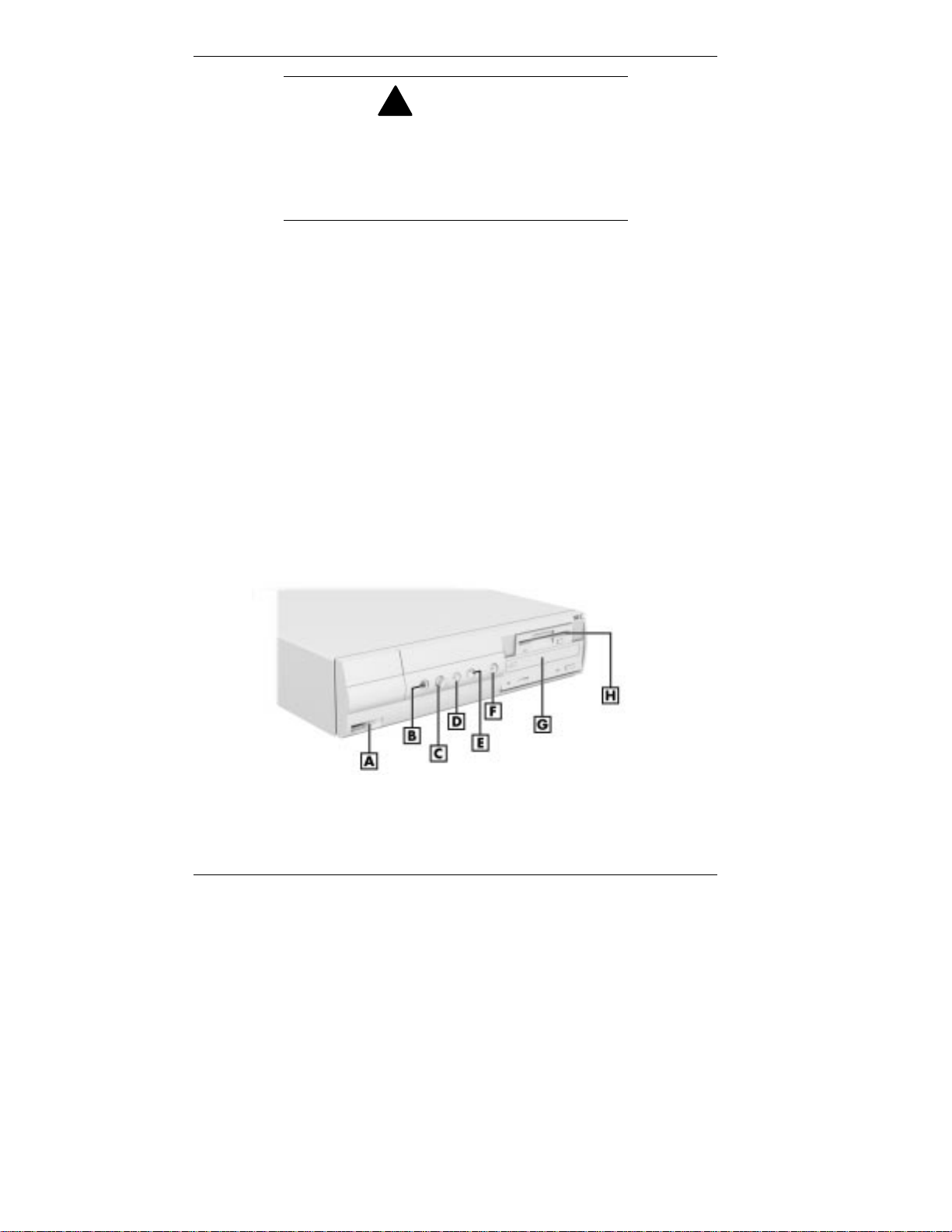
Front features — small desktop models
A
– USB Port
B
– Headphone Connector
C
– Volume Control
D
– Disk Lamp
1-2 Reviewing System Features
E
– Sleep Button/Lamp
F
– Power Button/Lamp
G
– CD-ROM Drive
H
– Diskette Drive
Page 16
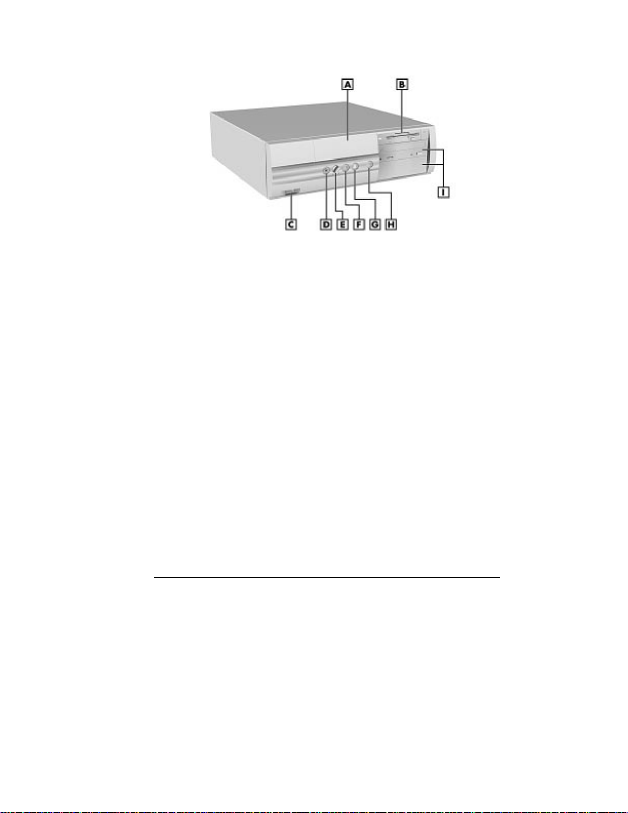
Front features — desktop models
A – Device Bay Cover F – Disk Activity Lamp
B – Diskette Drive G – Sleep But ton/Lamp
C – USB Port H – Power Button/Lamp
D – Headphone Connector I – 5 1/4-Inch Devices
E – Volume Control
Reviewing System Features 1-3
Page 17
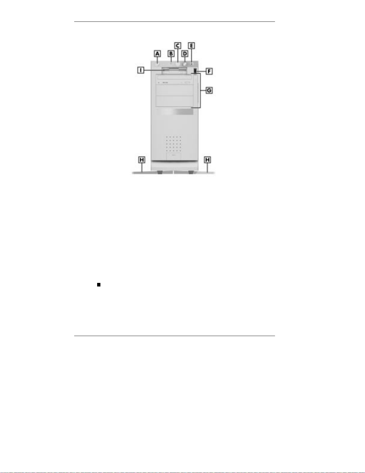
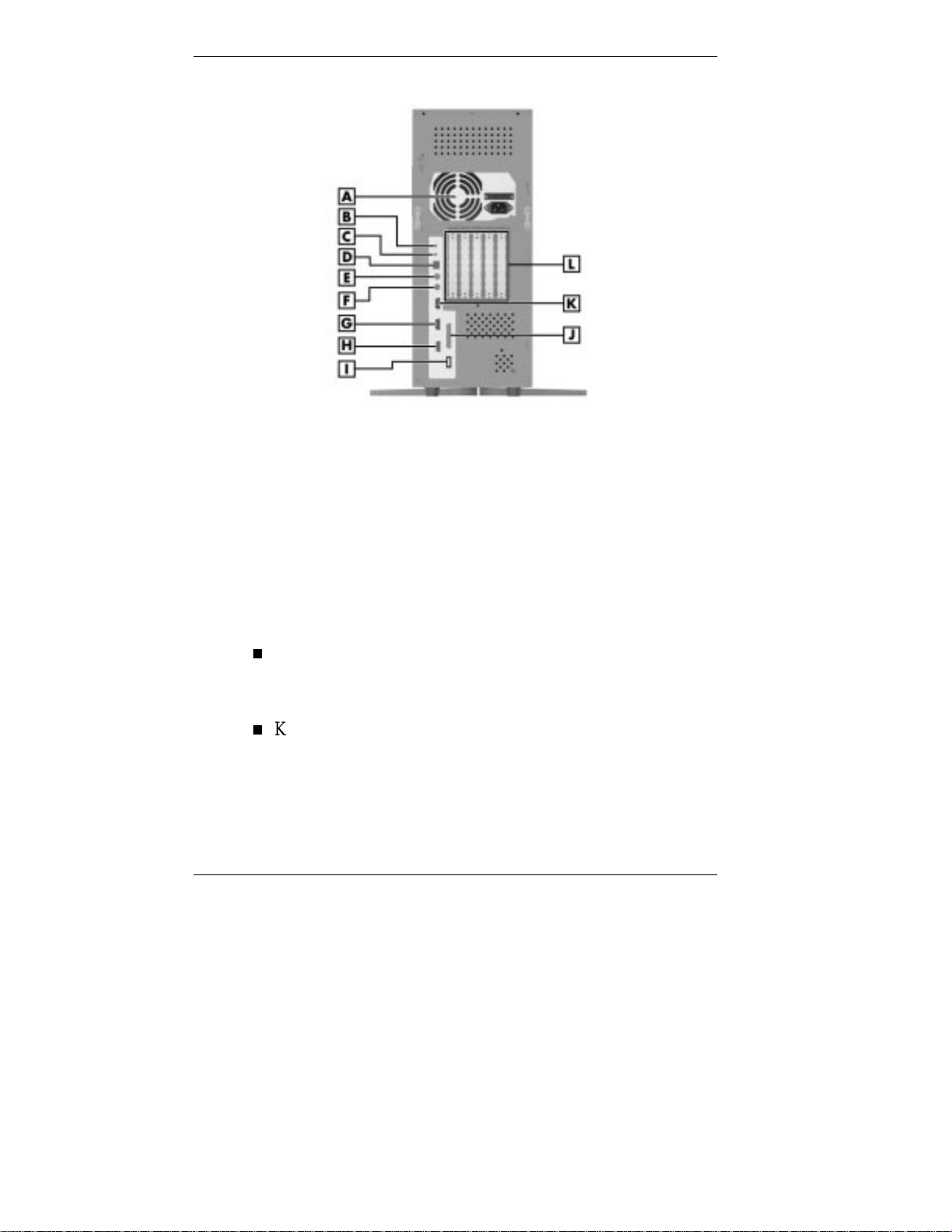
Front features — minitower models
A – Power Button/Lamp F – USB Port
B – Sleep Button/Lamp G – 5 1/4-Inch Accessible Bays
C – Disk Lamp H – Chassis Foot
D – Volume Control I – Diskette Drive
E – Headphone Connector
System Controls and Lamps
System contro ls let you se lect specific system operat ions.
Lamps let you know the status of system operation. The
figures in the previous sect ion show the co ntrols and lamps
on the front of each system. De scriptions of system controls
and lamps are provided below.
Power button
Press this button to turn on the system power. Press it
again to turn off the power.
1-4 Reviewing System Features
Page 18

Power lamp
The round lamp in the po wer button is lit when system
power is on.
!
CAUTION
Do not power off the system whil e the system is
in sleep mode.
Sleep button
Press th is but t on to suspend system operation when you
plan to be away from your computer for a short t ime. Press
any key or move your mouse to resume system operation
at the point where you stopped it.
Sleep la mp
A green lamp in the sleep butto n indicates t hat t he syste m
is in a power-saving mode.
If you have a VESA-compliant monitor, your monitor also
goes into a power-saving mode.
Disk la mp
The green lamp tells you that the hard drive is reading or
writing data.
!
CAUTION
Do not turn off the system unless absolutely
necessary while the disk lamp is lit. To do so can
damage your hard driv e or data.
Reviewing System Features 1-5
Page 19

Diskette Drive A
Use diskett e drive A to copy data files to and fro m a diskett e.
You can also use it as a bootable drive for loading and
starting pro grams from a diskette.
!
CAUTION
To prevent damage to your disket te drive and
data, do not turn off the system or remove a
diskette whil e the diskette drive busy lamp is lit.
Front Audio and U SB Access
The system featur es front access for audio and USB devices.
The following features are found on the front of the syste m:
Unive rsal Se rial Bus port
The Universal Serial Bus (USB) port allows you to add
new plug and play serial devices without opening up the
system. You simply plug the devices into the ports. The
USB determines syst em resources for each periphera l and
assigns them without user intervention. Up to 127 devices
can be daisy chained to the USB port.
Headphone jack
The headphone jack allows you to connect a headphone
set to th e front of the system.
Volume control
Th e volume co ntrol lets you adju st audio system volume.
1-6 Reviewing System Features
Page 20

CD-ROM Drive
Some systems come wit h a 32X or 40X Max variable
CD-ROM drive. Use the CD-ROM drive to load and start
programs from a compact disc (CD). Yo u can also use the
CD-ROM drive to play audio CDs.
Note:
CD-ROM drive with a bootable CD. To configure
the system to boot from the CD-RO M drive, see
“BIOS Features Setup” in Chapter 3.
The CD-ROM drive operates at different speeds depending
on whether the CD you are using contains data or music. This
allows you to get your dat a faster and to see smoother
animation and video.
DVD-ROM Drive
Some models come with a DVD-ROM drive. The
DVD-ROM drive offers many improvements over the
standard CD-ROM technology including superior video and
audio playback, faster dat a access, and great er stor age
capacities. The dr ive uses t he latest DVD technology that
reads from specially designed DVD discs as well as standard
audio and video CDs.
PC Card Adapter
You can boot your system from the
If your system has a PC card adapter, you can add PC cards
to the system. Inserting a PC card into a PC card slot is
similar to inserting a diskett e into a diskett e drive. E ach type
of PC card has a different function. One PC card adapter lets
you can add a number of capabilities to your syst em with a
variety of PC cards.
Reviewing System Features 1-7
Page 21

Tape Backup Unit
Some models come with a tape backup unit. If your system
has a tape backup unit, you can use it to quickly back up all
or part of your system’s files to a high-capacity tape
cartridge. Backup software helps you tailor the backup
process to protect your files and app lications. Files are
compressed during the backup process to conserve space and
to speed up the process.
Zip Drive
Some mode ls c ome with an A TAPI Zip® drive. Use the Zip
drive to back up work, archive old files, and transport your
work. Store up to 100 MB of data on a 3 1/2-inch Zip disk.
Rear Features
On the back of your computer, you’ll find external
connectors, power supply features, and expansion board slots.
The following figures show these features.
1-8 Reviewing System Features
Page 22
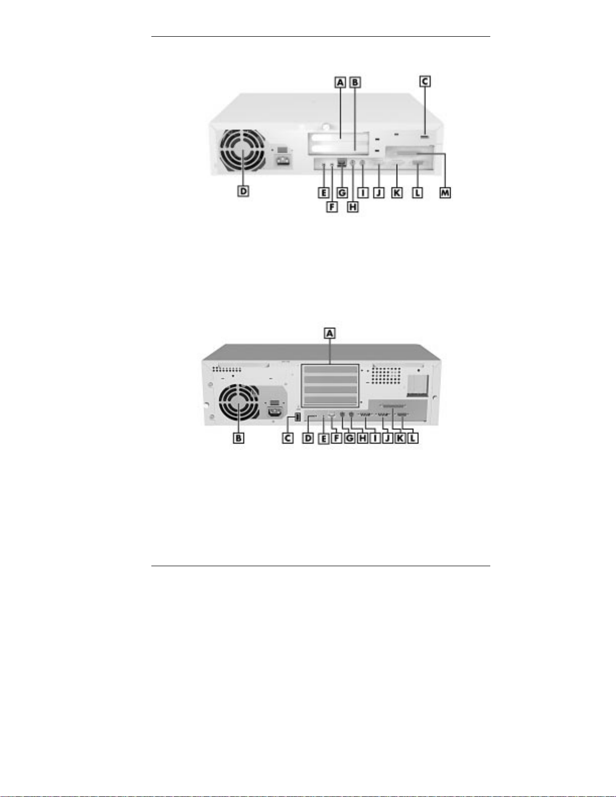
Rear features — small desktop models
A – PCI Slot H – Keyboard Port
B – PCI/ISA Shared Slot I – Mou se Port
C – USB Port J – Serial Port 2
D – Power Supply K – Serial Port 1
E – Line Out Jack L – VGA Monitor Connector
F – Microphone In Jack M – Printer Port
G – LAN Connector
Rear features — desktop models
A – Expansion Board Slots G – Keyboard Port
B – Power Supply H – Mo use Port
C – USB Port I – Serial Po r t 2
D – Line Out Jack J – Serial Port 1
E – Microphone In Jack K – Printer Port
F – LAN Connector L – VGA Monitor Connector
Reviewing System Features 1-9
Page 23
Rear features — minitower models
A – Power Supply G – Serial Port 1
B – Line Out Jack H – VGA Monitor Connector
C – Microphone In Jack I – USB Port
D – LAN Connector J – Prin ter Port
E – Keyboard Port K – Serial Port 2
F – Mouse Port L – Expansion Board Slots
External Connectors
External connecto r s let you att ach peripheral devices, such as
a monitor, keyboard, mouse, and printer to your s ystem. Your
system has the fo llow ing exter na l co nnect ors:
Mouse port
Attach the mouse that co mes w ith your co mputer to this
port. The mouse port supports a PS/2-compat ible mouse.
Keyboard port
Attach the keyboard that comes with your computer to the
ke yboard port.
1-10 Reviewing System Features
Page 24

The keyboard port supports a PS/2®-compatible (personal
system/2-compatible) 101-key or 104-key keyboard (in the
U.S. and Canada) or a 102-key keyboard (in the United
Kingdom and Germany) with a 6-pin mini DIN connector.
VGA mo nitor connector
The system supports the Accelerated Graphics Port (AGP)
standard, and comes with an external video graphics array
(VGA) connector. The connector support s an NEC
VistaScan™ monitor, NEC MultiSync® monitor, or other
VGA-compatible monitor with a 15-pin connector. Att ach
the signal cable from your monitor to the VGA connector
on the rear of the system.
Printer port
Use this port to connect a parallel printer with a 25-pin
connector to the system.
Serial ports (COM1 and COM2)
Attach a serial device with a 9-pin connector to each seria l
port. Serial devices include a pointing device, serial
printer, or a modem.
Unive rsal Se rial Bus port
This port adds a USB connection at the rear of the syst em
(see “Front Audio and USB Access”) .
LAN connector
The rear panel contains an RJ-45-compatible port for
connecting the syste m to an Ethernet local-area network
(LAN). Some systems also have a network board installed
in a PCI slo t.
The system board has an Intel 82558 LAN controller and
supports 10BASE-T/100BASE-TX Ethernet connections.
The controller also supports remote Wake-On LAN.
Reviewing System Features 1-11
Page 25

Audio connectors
The following connector s co me integrated on the system
board:
Microphone in jack
The microphone in jack lets you connect a microphone
for recording audio information in your data s ystem
files.
Line out jack
The line out jack allows you to connect an amplified
output device, such as powered speaker s, a stereo tape
recorder, or an external amplifier for audio output. If
you ordered speakers, use t his jack to connect t hem.
Fax/modem ports
Some systems come with a 56-kilobytes per second
(Kbp s) v.9 0 fax/modem board. The fax/modem bo a rd
allows the connection of a phone line to the computer for
fax and data communications functions.
Dual fax/modem ports let you use a telephone line for the
fax/modem and your telephone.
Power Supply Feat ures
The power supply has the following features:
Pow er supply fan
The power supply fan cools system components and
prevents them from overheat ing. Keep the area near t he
fan clear for proper vent ilation.
1-12 Reviewing System Features
Page 26

Voltage selector switch
This switch sets the system voltage to 115 or 230 volts.
!
CAUTION
Set the switch corr ectly for the voltage in your
area. Most wall outl ets in the United States and
Canada are 115 volts. O utlets in Europe,
Australia, and Asi a ( ex c ept T aiwan) are
230 volts. Taiwan uses 115-volt outlets.
Power socket
The power socket provides a connection for your power
cable.
Three-wire fan
The three-wire fan works with system software for fan
failure detection.
Power-on features
Power-on features include remote on/off, Wake-On LAN,
and Instant On ready.
Reviewing System Features 1-13
Page 27
Inside Features
See the follow ing figures for the location of features within
the system. Feature descriptions follow.
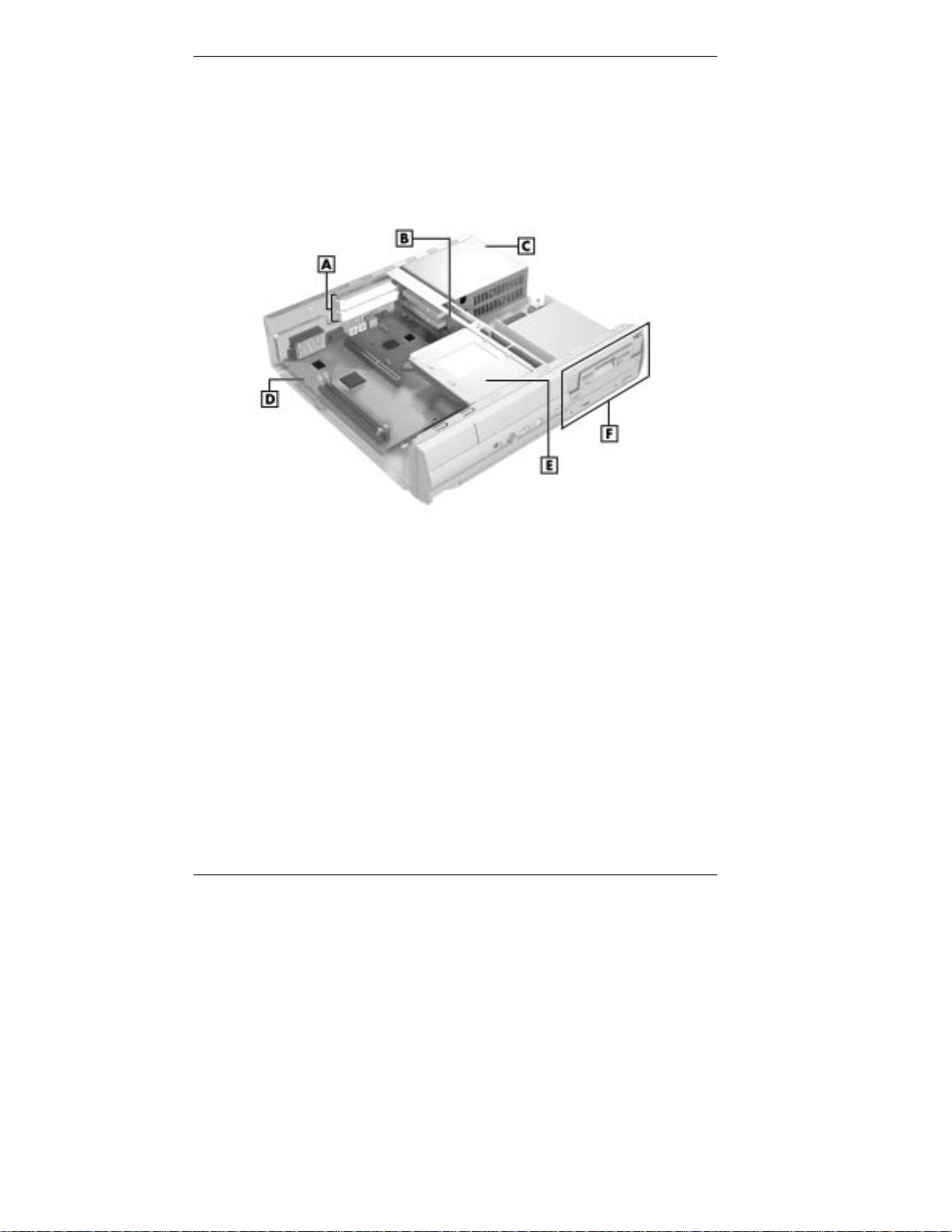
Inside the system — small desktop models
A – Expansion Slots D – System Board
B – Riser Board E – Internal Hard Drive
C – Power Supply F – Accessible Device Bays
1-14 Reviewing System Features
Page 28
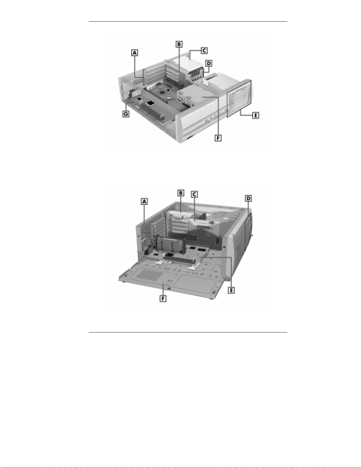
Inside the system — desktop models
A – Expansion Slots E – Accessible Device Bays
B – Riser Board F – Internal Hard Drive
C – Internal Hard Drive G – System Board
D – Power Supply
Inside the system — minitower models
A – Expansion Slots D – Accessible Device Bays
B – Power Supply E – System Board
C – Riser Board F – Chassis Floor
Reviewing System Features 1-15
Page 29

System Board
System memory, the processor, and the system battery reside
on the system board. The system board also comes with an
audio subsystem and a LAN controller, and it supports the
AGP standard.
See “Front Audio and USB Access” and “Exter na l
Connectors” for descriptions of external connector s.
The system board supports two diskette drives and up to four
IDE devices such as IDE hard drives, an IDE CD-ROM drive
or DVD-ROM drive, and an IDE Zip drive.
Riser Board
Most of the cable connectors in the system reside on t he riser
board. Riser board connectors include:
primary and secondary IDE co nnectors
diskette dr ive connector
front panel connector for lamp
the NLX connector for the syst em board
the external LAN connector
power connector s
additional connectors including the CD Audio In,
Modem In, Wake-On LAN, chassis intrusion (hardware
monitor), and fan connectors.
Expansion board connectors on the riser board are as follows:
S mall desk top models
one PCI connector
one shared PCI/ISA connector
1-16 Reviewing System Features
Page 30

Desktop models
two PCI connectors
one shared PCI/ISA connector
one ISA connector
Minitower models
three PCI connecto r s
two ISA connector s.
Chassis
Each model has a stat e of the art chassis de s ign. T he chas s is
provides the following featur es that make the system easy to
use, upgrade, repair, and secure:
a sturdy design
easy upgradeablilty, so internal devices can be installed
riser board with an NLX connector for signal and power
The chassis supports the following storage device
configurations:
S mall desk top models
Note:
connector next to t he ISA connector. This
connector is not support ed and c annot be used.
Some minitowers have a fourth PCI
wit h only a screw d river
standardized size and dimensions to accommodat e NLX
form factor system boards
circuitry to keep the syste m board largely cable free.
Three bays accommodate an internal 3 1/2-inch hard drive,
a 3 1/2-inch diskette drive, and a 5 1/4-inch accessible
device.
Reviewing System Features 1-17
Page 31

Stand
The minitower system unit has feet to prevent it from being
tipped over. This is a safety feature to prevent personal injur y
and equipment damage. Keep the feet turned out at all times
except when opening or upgrading the system.
Desktop models
Five bays accommodate an internal 3 1/2-inch hard drive,
a 3 1/2-inch diskette drive, a 3 1/2-inch device (for a
diskette drive or a hard drive), and two 5 1/4-inch
accessible devices.
Minitower models
Six bays accommodate two internal 3 1/2-inch hard drives,
a 3 1/2-inch diskette drive, and three 5 1/4-inch accessible
devices.
!
WARNING
Turn the feet out under the system unit. The feet
are designed to keep the unit from being tipped
over.
Minitower foot — left side shown
1-18 Reviewing System Features
Page 32

Speakers
Some systems come with a pa ir of high-qualit y st er eo
speakers that you can arrange to suit your wor k environment.
An AC adapter comes with the speakers if you o r der ed
speakers. Set up the speakers w ith the AC adapt er .
Note:
with your speakers for information on setting up
and using the speakers.
Adjust the speaker volume by using the volume control on
the front of the right speaker or by using the Windows sound
software. To bring up a volume control, double click the
speaker icon on the taskbar (next to the syst em clock). Also
use the sound software to balance the so und betwee n t he left
and right speakers.
See the documentati on that c om es
System Features
Your computer hardware and software deliver the
performance and technologies you need for all your
challenging tasks today and into the future.
Hardware
PowerMate ES 5200 Series systems include the follow ing
hardware features:
Latest in Pro cessor Technology
The system comes with an Intel Pentium® II, Celeron™,
or Pentium III processor. These are fast, powerful
processors for heavy-duty computational, graphical, and
net working t a s ks.
Reviewing System Features 1-19
Page 33

Audio on the System Board
The system board comes w ith an audio subs ystem. The
audio chipset gives you a surro u nd sound system for threedimensio nal sound effects — much like a live
per forma nce! I t also prov ides wavetable synthesis.
(Wavetable synthesis use s actual recordings of real sound
effects and musical inst r uments for a dynamic audio
experience.)
Flashable ROM BIOS
The syste m’s RO M BIOS features system setup
configuration, Plug and Play support, and flash support for
easy and economical BIOS upgrades.
Syste m Memory
Your computer comes with at least 32 MB o f SDRAM and
supports up to 512 MB.
Motion Video Playback Controller
Your motion video playback hardware gives you fullmotion, full-screen smooth-scaled video playback and
supports Motion Picture Experts Group (MPEG) software.
Po wer Manageme nt Options
Power management options conserve energy and reduce
power costs.
Software
NEC CSD provides a variet y of applications and hardware
utilities with your system to let you take advantage of your
hardware capabilit ies.
Preloaded Operating System
The Microsoft® Windows NT®, Windows® 95, or Windows
98 operating system comes loaded o n the system.
1-20 Reviewing System Features
Page 34

NEC OS Restore CD
In the event of operat ing system problems, you can restore
your operating system using the NEC OS Restore CD. The
NEC OS Restore program on the CD performs a complete
restore of the operating system. It also provides options for
reformatting and repartitioning the hard drive. In addition, the
program automatically deter mines which drivers ar e needed
for your original hardware configuration and installs them
during the restore.
NEC Application and Driver CD
Install or reinstall any of the applications and drivers
provided by NEC CSD from the NEC Applicat ion and Driver
CD.
Each item on the NEC Application and Dr iver CD is
selectable fro m a str aightforward graphical interface. Clear
menu descriptions and the help screens guide you thro ugh
each step.
The following applications and utilities are provided on the
NEC Application and Driver CD:
Microsoft Internet Explorer
Internet Exp lorer prov ides a top-no tch br owser with
preloaded links for easy access to t he world wide web.
Also use Internet E xplorer to access one of the many new
browser-based utilities. Internet access r equires a network
connection.
®
4.01
Netscape Bro wser 4.5
Browse the web with Netscape Navigat or. Internet access
requires a network connect ion.
Reviewing System Features 1-21
Page 35

Intel LANDesk® Client M a nager
Use LANDesk software to tr ack system information suc h
as serial number, BIOS version, memory capacity, disk
capacity, expansion board settings, and applications. Use
LANDesk software for remote starts from a server
computer using Wake-On LAN and remote reboot.
NEC T oolTellige nt™ Suite
Manage computers in the network with the NEC
ToolTell igent Suite. Too lT elligent fea tur e s the following :
NEC WebTelligent™Software
Manage computers in the network from a server
system running NEC WebTelligent using an Internet
browser of your choice.
NEC WebTelligent™Auto Discovery Agent
Install NEC WebTelligent Auto Discovery Agent on
client s ystems s o the y can be manage d with the NEC
WebTelligent software.
NEC Desktop SNMP Agent
Use the S imple Network Manag ement Protoco l
(SNMP) Agent to monitor the features, configurations,
and locations of computers in your networ k.
NEC Configuration Change Notification (CCN)
Use NEC CCN to detect and announce changes in the
processor, main memory, or hard drive wh en the
operat ing system starts.
NEC Auto Backup Utility
Use NEC Auto Backup to back up the hard drive when
hard drive failure is imminent.
1-22 Reviewing System Features
Page 36

LapLink® Enterprise
Use LapLink software for tr ansferring files, accessing files
on remote systems.
PartitionMagic
™
Repartition your hard drive while leaving your data intact
with PartitionMagic. Includes BootMagic™ software for
eas il y ma nag in g mu lt ip le o p er a t ing systems.
DirectX
Use the DirectX API to develop multimedia applications
that can be used across video, sound, or network
platforms. DirectDr aw, DirectSound, DirectPlay,
DirectInput, and Direct3D are some of the components
that make up the DirectX suite.
Networ k Associate VirusSca n® Software
Protect the system from viruses by running VirusScan
softwar e.
The following online documentation is also provided on the
NEC Application and Driver CD:
The NEC Help Center
This is an online guide to NE C Po wer Mat e syst ems.
Healthy Environment
This is an online version of the printed brochure, Setting
up a Healthy Environment.
Reviewing System Features 1-23
Page 37

Security
The system has hardware, software, and mechanical security
features that offer protection against unauthorized access to
your system and data. The following security featur es ar e
available with the system:
Passwor d security
Windows network secur it y features
The CMOS Setup Utility includes a featur e that lets you
set up either a user or supervisor password, or both.
The user password controls booting of the system and
controls access t o t he Set u p utility and the keyboard. ( User
access to the CMOS Set up Utility is limited t o a subset of
all CMOS Setup parameters when a supervisor password
has been set.)
The supervisor password allow s full access to the system
and the BIOS.
To learn more about the netwo r k securit y featur es
available through the Windows o perating system, re fer to
your Windows documentation or consult your system
administrator.
Chassis intrusion notificat ion
Whenever the chassis cover is removed, LANDesk Client
Manager logs the incident and then reports it on screen the
next time the system is rebooted.
1-24 Reviewing System Features
Page 38

2
Setting Up the System
Cable Connections
Startup
Shutdown
Power-Saving Operation
System Care
More Information
Page 39

This chapter provides the informat ion you need to set up and
use the PowerMate ES 5200 small deskto p, deskto p, and
minitower computers. So me of the informat ion provided
includes cable connections, system startup procedures,
system shutdown procedur es, and system care. The chapter
also provides a matrix show ing where to find additional
information about your system.
Cable Connections
In this section find guidelines on setting up your system.
Connect the s yst em components as follows:
!
WARNING
In minitower system s, turn the feet out before
connecting any of t he cabl es or powering on the
system.
See the Quick Setup poster for diagrams show ing most
cable connections.
Use the icons on the rear of the syst em unit to identify
connectors.
If the system comes with a fax/mode m boar d, connect it to
the telephone line as follows:
Unplug the telephone from the wall jack.
Plug the telephone cable that co mes w ith the syst em
into the lin e jack on the sys te m an d into the telephon e
jack on the wall.
Plug the cable on the telephone into the phone jack on
the system.
2-2 Setting Up the System
Page 40

See your network administrator for guidelines on
configuring the system for network access.
Set the voltage switch cor r ectly for your area. The correct
setting for the U.S. and Canada is 115V.
!
WARNING
Set the voltage switch corr ec tly for your area.
Connect syste m power co nnectors to a surge protector
(recommended) or a properly grounded wa ll outlet.
Immediate Boot - Up, t he system star ts up as
soon as the power cord is connect ed. See
“Startup” and “Jumper S etti ngs.”
NEC CSD recommends connecting power cables
to a surge protector.
Startup
You can start up the system in two ways:
by pressing the power button
by connecting the power cable (if the system board is
jumpered for Immediate Boot-Up).
When the system star ts up, the power lamp lights green to
indicate t hat the syst em is on. The NEC startup screen
appears.
Note:
If the system board has been set for
!
CAUTION
Setting Up the System 2-3
Page 41

At the bottom of this scree n, a mess age like the following
appears:
Press [ESC] to show POST, [F2] to enter SETUP.
Note:
performs a Power-On Self- Test (POST) to check
your hardware for any c hanges since the last
startup. To see the messages displ ay ed dur ing
POST, press
Setup Utility, press F2.
When your system is started, it
. If you want to go into the
Esc
One beep indicates that the system has successfully
completed the power-on test. After about 5 seconds,
Windows starts up.
If a problem occurs, a series of beeps may so und. I f this
happens repeatedly after powering on, power off the system
and turn to Chapter 6, “Solving System Problems.” This
chapter provides helpful hints on obvious system problems.
Note:
indicati ng that system settings have changed,
run the CMOS Setup Utility ( see Chapter 3,
“Configuring the System”).
If the system displays a message
On systems loaded with the Windows NT® 4.0 operating
syste m, pr ess
Ctrl Alt Del
The log-on box appears for enter ing a password.
2-4 Setting Up the System
when prompted on-screen to do so.
Page 42

Shutdown
Follow these steps to shut down (po wer off) your computer.
1. Save your work. See the documentation that comes wit h
your application.
2. Exit t he a pplic at ion program.
3. Make sure that the hard drive, diskette drive, and any
other drives are not in use. A lit device lamp indicates that
the device is in use.
Wait until a program i s finished running before
shutting down the system.
Unless absolutely nec essary, never shut down
the system when the sleep lam p is lit, or when
the hard drive lam p, diskette drive lamp, or other
device lamp is lit. Information on the device might
be lost or damaged.
!
CAUTION
4. Click
Shut Down
choices in the pop-up submenu. Select
computer
Note:
informing you when it is safe to turn off your
system, the system usually powers off by itself.
on the taskbar, then point to and click
Start
. Selecting
, then click
Although a message appears
Shut Down
or press
Yes
gives you several
Enter
Shut down the
for shut down.
5. The system should power off by itself. If it does not, press
the system unit power button. The system powers off after
a 5- to 10-second delay.
6. Turn off power to your monitor.
Setting Up the System 2-5
Page 43

Power-Saving Operation
If the system is running the Windows 95 or Windows 98
operating system, you can put it in Sleep mode — a powersaving state — by pressing the sleep butto n on the front of
your unit. This is a convenient way of conserving energy
when you are going to be away from your system for a short
period of time.
The system also goes into Sleep mode when the system has
been inactive, if the power manag ement has be en enabled in
BIOS, and an inactivity timeout has been enabled.
!
CAUTION
The sleep button is next to t he power button.
Take care not to press the power button when
you put the system in sleep mode. If you
accidentally press the power button, you can lose
any data that has not been sav ed.
When the system goes into S leep mode, it saves data and
system status and then shuts off power to all possible
components. Sleep mode lets you save power without first
saving your work.
The sleep button lights when t he syst em is in Sleep mode.
Press the sleep button, press a key, or move the mouse to
resume system oper ation where you left off.
Sleep mode provides several levels power management.
Leve ls inc lu d e:
Doze mode
Standby mode
Suspend mode.
2-6 Setting Up the System
Page 44

In addition, you can configure conditions under which your
monitor and hard drive are placed in a power-saving stat e.
See “CMOS Setup U tility” in Cha pter 3 for mo re infor matio n
on using power management features.
System Care
Your system is a durable, dependable computer built for
heavy use. With protective measures and pro p er care, you can
prevent problems and promote the successfu l operation and
long life span of your computer.
Protecting Your System From Damage
There are several ways that you can prot ect your syst em from
po ssible damage. NEC C SD strongly rec omme nds t he
following protective measures:
Keep the feet on the minitow er syst em turned out. The feet
prevent the system fro m being tipped over. This is a safety
feature to prevent personal injury and equipment damage.
Connect a surge suppressor between your computer and a
grounded wall outlet. A surge suppressor protects your
system from sudden transient increases and decrease s in
electrical power.
Be sure to connect all peripherals, such as your monitor
and printer, to the surge suppressor. The surge protector
should be the only device that you plug into the wall
outlet.
Avoid repeated power-o n c ycles. These subject the system
components to temperature variations and stress.
Setting Up the System 2-7
Page 45

Disconnect your system from telephone and power lines
when an electrical sto r m threat ens. I f you have a
fax/modem, lightning can travel in on the phone line and
damage both the fax/modem and the system unit.
Lightning can also travel in on power lines and damage
your monitor and system unit.
Be sure that system power is o ff before you co nnect or
disconnect a cable. Never make cable changes when the
system power is on. Doing so can damage the system and
its peripher als.
Use CMOS Setup Utility options to protect against viruses
(see “BIOS Features Setup” in Chapter 3). Use appro priate
virus detection software regularly to protect your system
from computer viruses.
If you plan to use software programs other than NEC CSD
supplied soft w are, NEC CS D s trongly recomme nds that
you take the necessary st eps, such as virus checks, to
protect your system.
Place your computer away from direct sunlight and
extreme hot and cold temperatures.
The recommended operating environment is from 32°F to
95°F (0°C to 35°C).
After turning off power, wait about five seconds for the
hard drive to spin down before you power on again.
Be sure that nothing is placed on top of your system power
cables.
Prevent dust from entering your system by covering it
when it is n ot in u s e .
2-8 Setting Up the System
Page 46

Keeping Your System in Good Condition
Maintain the condition of your system by periodically using
the following general procedures.
!
WARNING
For safety, power off and unplug your system,
monitor, and any external devices before
cleaning them.
Clean the outside of the computer with a soft clean cloth.
Yo u can re move st ubborn stains w ith a cloth slightly
dampened with a mild detergent . Never use a strong
cleaner or solvent on any part of the system.
Keep food and liquids away from your computer.
Periodically clean the keyboard with a vacuum cleaner
brush attachment. Do not use any liquid cleaners o n the
keyboard as they can damage the keyboard.
If an object, such as a paper clip, falls into the keyboard,
turn the keyboard over and gently shake it to dislodge the
object.
Clean the monitor screen wit h a g lass clea ner and wipe it
with a clean, lint-free cloth. You may use wet/dry cleaning
pads manufactured for monitor screens.
Setting Up the System 2-9
Page 47

Moving or Shipping Your System
Use these steps to pr epar e your syst em for moving or
shipping:
1. Back up the files on the hard dr ive to diskettes, Zip disks,
or ta pe cartridges.
Be sure to take precautions for storing and transporting
Zip disks, diskettes, or t ap e cart r idge s so that they are not
exposed to magnetic fields or electrical impulses.
2. Remove any diskette from the diskette drive. If you have
a CD, Zip disk, or tape cartridge in a drive, remove it.
3. Turn off the system unit and any external options
connected to it.
4. Unplug the syst em unit power cable from the wall out let
or surge suppressor, then from the unit itself.
5. Unplug any external options from the wall outlets or
surge suppressor, then disconnect t hem fro m the system
unit.
6. Pack the system co mponents in the original shipp ing
materials and carto ns. If these are not available, be sure to
use adequate packing materials to prot ect the components.
To set up your system, follow the step s on the PowerMate E S
5200 Series Quick Setup poster that comes with the computer.
2-10 Setting Up the System
Page 48

More Information
Once you have your system up and running, we suggest that
you do the following:
Install applicat ions provided by NEC CSD from the NEC
Application and Driver CD.
See “Setting Up a Healthy Work Environment” in
Appendix A.
Install any of your own applications. See the
documentation that comes w ith the app lication.
As needed, upgrade your system with more memory, a
storage device, or a faster pro cessor. See Chapter 5,
“Installing Options.”
See the following quick reference chart to find infor mat ion
about using the computer.
Quick Reference to Information About the Computer
Information Where to Find It in This Guide
Installing applications provided by NEC CSD "NEC Application and Driver CD" in
Chapter 3
Finding basic information on the computer Chapter 1
Configuring the system and peripherals Chapter 3
Managing system and networked resources Chapter 4
Adding options Chapter 5
Accessing the world wide web Chapter 7
Using support services Chapter 7
Troubleshooting system problems Chapter 6
Setting Up the System 2-11
Page 49

3
Configuring the System
Configuration Tools and Utilit i es
CMOS Setup Utility
Flash Utility
NEC OS Restore CD
NEC Application and Dri ver CD
NEC Help Center
Resolutions for NE C VistaSc an USB
Monitors
Jumper Settings
Page 50

This chapter provides information on configuring your
computer. It includes information about the CMOS Setup
Utility for configuring hardware and the system. It also
provides informat ion about the Flash utility for BIOS
updates, the NEC OS Restore CD for rebuilding the hard
drive and/or restoring the operating system, and the NEC
Application and Driver CD for installing the NEC-supplied
applications and opt ional drivers. In add it ion, it provides
jumper settings for physically configuring devices in the
system.
See the following table for a quick guide to the configuration
utilities, tools, and procedures. For detailed information about
these and other tools, see t he sections following the table.
Configuration Tools and Utilities
The following table lists ways you can configure the system,
and the utility, tool, or procedure to use for the configuration.
Note:
System Resources,” f or ways to manage system
resources and to configure the system remotely.
Also see the next chapter, “Managing
Configuration Tools and Utilities
Configuration Method, Tool, or Utility
Adding or removing hardware (hard drive,
diskette drive, CD-ROM drive, tape backup)
Base I/O address, changing CMOS Setup (Integrated
BIOS, updating FLASH utility
CMOS Setup (Standard
CMOS Setup menu, Integrated
Peripherals menu)
Peripherals menu)
3-2 Configuring the System
Page 51

Configuration Tools and Utilities
Configuration Method, Tool, or Utility
Boot devices, determining CMOS Setup (BIOS Features
Setup menu)
Boot order, changing CMOS Setup (BIOS Features
Setup menu)
Configuring hardware CMOS Setup (Integrated
Peripherals menu)
Jumper Settings
CPU serial number tracking (Pentium III),
disabling
Date, setting CMOS Setup (Standard
DIMM memory, checking CMOS Setup (Standa rd
Diskette drive, enabling CMOS Setup (Standard
DMA, assigning CMOS Setup (Integrated
DMI event log, s etting, configur ing, viewing CMO S Setup (BIOS Features
Drivers for NEC CSD hardware, in stall ing NEC Driver CD
Har d driv e, configuring as m aster or slave,
primary or secondary
Hard drive, reformatting NEC OS Restore CD
Hard drive, repartioning NEC OS Restore CD
Hard drive, set ting a pre-delay CMOS Setup (BI OS Fea tures
CMO S Setup (BIOS Features
Setup menu)
CMOS Setup menu)
CMOS Setup menu)
CMOS Setup menu)
Peripherals menu, Special
Features Setup menu)
Setup menu)
CMO S Setup (Integ rated
Peripherals menu)
PartitionMagic
Setup menu)
Hard drive, subjecting to power management CMOS Setup (Power
Management Setup menu)
Configuring the System 3-3
Page 52

Configuration Tools and Utilities
Configuration Method, Tool, or Utility
Hardware, adding CMOS Setup (Standard
CMOS Setup menu, BIOS
Features Setup menu, Power
Management Setup menu)
Healthy Envir onment (online document),
installi ng
IDE device, configured as primary or
secondary device
IDE device, configuring as m aster or slave CMOS Setup ( Integrated
Inactivity timeout, setting CMOS Setup (Power
IRQ s, changing CMOS Setup (Integra ted
ISA PnP resource control CMOS Setup (PNP/PCI
Keyboard options, configuring CMOS Setup (Integrated
L2 Cache ECC Support, enabling CMOS Setup (BIOS Features
Legacy ISA resource control CMOS Setup (PNP/PCI
Memory, checking CMOS Setup (Standard
NEC Application and Driver
CD
CMO S Setup (Integ rated
Peripherals menu)
Peripherals menu)
Jumper Settings
Management Setup menu)
Peripherals menu, Special
Features Setup menu)
Configuration Setup menu)
Peripherals menu)
Setup menu)
Configuration Setup menu)
CMOS Setup menu)
NEC H elp Cen ter online d ocumentation,
installi ng
NEC H elp Cen ter online d ocumentation,
uninstalling
3-4 Configuring the System
NEC Application and Driver
CD ( see “Installing t he NEC
Help Center”)
see “Uninstalling the NEC Help
Center”
Page 53

Configuration Tools and Utilities
Configuration Method, Tool, or Utility
Onboard sound, onboard LAN, enabling CMOS Setup (Integrated
Peripherals menu)
Operating system, restoring NEC OS Restore CD
Parallel port, enabling, configuring CMOS Setup (Integrated
Peripherals menu)
Pas sword, setting or clearing (user,
supervisor, or both)
PCI/ISA PnP resource control CMOS Setup (PNP/PCI
Plug and Play, enabling CMOS Setup (PNP/PCI
Power management, enabling, configuring CMOS Setup (Power
Pentium I II process or serial number, disabl ing CMO S Setup (BIOS Features
Processor speed, ch anging CMO S Setup (Special
Serial ports, enabling CMOS Setup (Integrated
Software provided through NEC, installing NEC Application and Driver
Time and date, setting CMOS Setup (Standard
Wake-On LAN (boot the system from a
remote server), enabling
CMO S Setup (Super visor
Password menu, User
Password menu)
Configuration Setup menu)
Configuration Setup menu)
Management Setup menu)
Setup menu)
Features Setup menu)
Peripherals menu)
CD
CMOS Setup menu)
CMO S Setup (Power
Management Setup menu)
Video palette snoop, enabling CMOS Setup (BIOS Features
Setup menu)
Video AGP aperture, setting CMOS Setup (Chipset
Features Setup menu)
Configuring the System 3-5
Page 54

Configuration Tools and Utilities
Configuration Method, Tool, or Utility
Video device, assigning IRQ for CMOS Setup (PNP/PCI
Configuration Setup menu)
Video device, subjecting to power
management
Virus protection, enabling CMOS Setup (BIOS Features
Windows 95, Windows 98, or Windows NT,
restoring
CMO S Setup (Power
Management Setup menu)
Setup menu)
NEC OS Restore CD
CMOS Setup Utility
The CMOS Setup Utility is a progr am for configuring the
BIOS settings for the main components of your computer.
Your system ships from the factory with the corr ect system
parameters for your configuration. Unless you add optional
hard ware, you do not need to run the CMOS Set up Utility t o
operate your system. However, you might wish to run the
Setup utility to set features t hat customize your system, such
as power management and security featur es.
System configuration information is stored in nonvolatile
memory. A nonvolat ile memo ry device re tains its data whe n
system power is turne d off. Nonvolat ile memo ry in yo ur
system is s tored in a complementa ry metal-oxide
semiconductor (CMOS) chip backed up by a batt ery on the
system board. The battery supplies continuous power to
CMOS memo r y and ma int ains co n fig u r at io n in fo rm atio n
when system power is off.
3-6 Configuring the System
Page 55

NEC CSD recommends that you print out or write down your
current CMOS Setup parameters and sto r e the information in
a safe place. This let s you restore your system to the current
parameters if you ever need to replace the battery.
How to Start CMOS Setup
To start the CMOS Set up Ut ility, fo llow t hese st eps:
1. Turn on or reboot the system.
2. Press F2 as soon as you see this message:
Press [ESC] to show POST, [F2] to enter SETUP.
Yo u have a bout fi ve seconds to pr e s s F2 before the
system boot cont inues.
3. Setup ’s Ma in me nu app ear s and looks similar t o t he
following scre en.
CMOS Setup Ut ility Main menu
A
– Menu Title
B
– Selected Menu Item
C
– Menu Items
D
– Navigation Keys
E
– Description of Selected Menu Item
Configuring the System 3-7
Page 56

How to Use CMOS Setup
Use the keys described in the narrow legend near the bottom
of the Setup menu to make your selections or exit the current
menu. The following table describes the navigation keys.
Navigation Keys
Key Function
Esc Quits th e menu.
Enter Executes Command or brings up
a su bmenu.
↑ or ↓ arrow keys
← or → arrow keys
F1 or ESC Help
To display a submenu, use the arrow keys to move the cursor
to the submenu you want. Then press
Main Menu
The CMOS Setup Utility comes up displaying the Main
menu. See “How to Start CMOS S et up” for a look at a typical
main me n u scr e e n.
The ma in me nu pr o v ides me nu it e ms fo r te n set u p functions
and two exit choices. Use t he arro w keys to select a menu
item. A brief description of the option appears along the
bot tom of the Ma in menu sc reen when a menu item is
selected.
Moves cursor up and down.
Moves cursor left or right
.
Enter
3-8 Configuring the System
Page 57

The following menu ite ms are available from the Main menu.
Standard CMOS Setup
BIOS Features Set up
Chipset Featur es S etu p
Po wer Manageme nt Setup
PNP/PCI Configuration Setup
Load Setup Defaults
Special Features S etu p
Integrated Peripherals
Supervisor Password
User Passwo rd
Save & Exit Setup
Exit Without Saving
Press
to bring up the selected submenu. Items with
Enter
grayed-out text are not changeable from the submenu.
Note:
and Utilities” at the beginning of this chapter also
lists specific ways to conf igure the system and
the CMOS Setup Utility function or other utility
you use for each.
The table called “Configur ation Tools
Standard CMOS Setup
Choose the Standard CMOS Set up menu by select ing it from
the Main menu and pressing
The following infor mation is displaye d in the Standard
CMOS Setup menu.
.
Enter
Configuring the System 3-9
Page 58

Date
Time
Hard disk type, size, cylinders, heads, preconfiguration
mode
Diskette Drive
Base Memory
Extended Memory
Other Memory
Tot al Memory
BIOS Features Setup
Choose the BIOS Featur es S etup menu by select ing it from
the Main menu and pressing
!
Setting items on this menu t o inc or r ec t values
can cause your system to malfunction.
.
Enter
CAUTION
This menu provides access to enhanced BIOS features. The
following features are available from the BIOS Features
Setup menu .
Anti-Virus Protection
CPU L2 Cache ECC Checking
Processor Number Feature
Quick Power-On Self Test
Boot from LAN First
Boot Sequence
3-10 Configuring the System
Page 59

Boot Up Num Lock Status
Gate A20 Option
Security Option
PCI/VGA Palette Snoop
OS Select for DRAM > 64MB
Delay For HDD (Secs)
DMI Event Log
Clear All DMI Event Log
View DMI Event Log
Mark DMI Events as Read
Event Log Capacity
Eve nt Lo g Validity
Chipset Fe at ur es S et up
Choose the Chipset Features Setup menu by selecting it from
the Main menu and pressing
Enter
.
!
CAUTION
Setting items on this menu t o inc or r ec t values
can cause your system to malfunction.
The following features are ava ilab le fro m the Chipset
Features Set up menu.
DRAM Data Integrity Mode (for example, No n-ECC or
ECC)
Memory Hole at 15M-16M
AGP Aperture Size (MB)
Configuring the System 3-11
Page 60

Power Management Setup
Choose the Power Manageme nt Setup menu by selecting it
from the Main menu and pressing
!
CAUTION
Setting items on this menu t o inc or r ec t values
can cause your system to malfunction.
The following features are availab le from the Po wer
Mana geme nt Setup me nu.
Po wer Manageme nt
PM Control by APM
Video Off method (suspend, standby, doze, NA)
Video O ff After
MODEM Use IRQ
Reserve IRQ 9
Enter
.
Doze Mode
Standby Mode
Suspend Mode (disabled by default if Power Management
is disabled)
HDD Power Down (disabled by default if Power
Management is disabled)
HDD Down When Suspend
Soft-Off by PWR-BTTN (instant-off/delay 4 seconds)
CPUFAN Off In Suspe nd
PWRFAN Off In Suspend
3-12 Configuring the System
Page 61

Resume by Ring
Resume by Alarm
Date (of Month) Alarm (appe ar s only when Resume b y
Alarm is enabled)
Time (hh:mm:ss) Alarm (appears only when Res u me by
Alarm is enabled)
Wake Up On LAN
Restore AC/Power Loss
IRQ[3-7,9-15],NMI
Prima ry IDE 0
Prima ry IDE1
Secondary IDE 0
Secondary IDE 1
Floppy Disk
Serial Port
Parallel Port
PNP/PCI Configuration Setup
Choose the PNP/PCI Configuration Setup menu by selecting
it from the Main menu and pressing
!
CAUTION
Setting items on this menu t o inc or r ec t values
can cause your system to malfunction.
The following features are availab le from the PNP/PCI
Configuration Setup menu.
Configuring the System 3-13
Enter
.
Page 62

PNP OS Installe d
Resources Controlled By (for IRQs 3, 4, 5, 7, 9, 10, 11,
12, 14, and 15, with settings for PCI/ISA PnP or
Legacy I SA)
Reset Configuration Data
Assign IRQ For VGA
Assign IRQ For USB
Load Setup Defaults
Choose the Load Setup Defaults menu by selecting it fro m
the Main menu and pressing
you can confirm this choice, or abort the process.
Setting items on this menu t o inc or r ec t values
can cause your system to malfunction.
!
CAUTION
. A dialog box appears so
Enter
Special Features Setup
Choose the Special Features S etup menu by selecting it fro m
the Main menu and pressing
!
CAUTION
Setting items on this menu t o inc or r ec t values
can cause your system to malfunction.
3-14 Configuring the System
Enter
.
Page 63

The following features are availab le from the Specia l
Features Set up menu.
under POST SHOWING
Chassis Fan Detected
Power Fan Detected
CPU Fan Detected
Chassis Intrusion Detect
Voltage Detected
under CPU PLUG & PLAY
CPU Speed:
Disable
Manual
200 MHz (66 x 3)
233 MHz (66 x 3.5)
266 MHz (66 x 4)
300 MHz (66 x 4.5)
333 MHz (66 x 5)
366 MHz (66 x 5.5)
400 MHz (66 x 6)
under System Monitor
Chassis Fan RPM
Power Fan RPM
Configuring the System 3-15
Page 64

CPU Fan RPM
System Temperature
CPU Temperat ur e
CPU Cr itical Temp
Shutdown Temp
Integrated Peripherals
Choose the Integrated P er iphera ls me nu by selecting it from
the Main menu and pressing
!
Setting items on this menu t o inc or r ec t values
can cause your system to malfunction.
The following features are availab le from the Integrated
Peripherals menu.
.
Enter
CAUTION
IDE HDD Block Mode
IDE Primary Master PIO (only appears when On-Chip
Prima ry PCI IDE is se t to e nabled)
IDE Primary Slave PIO (only appears when On-Chip
Prima ry PCI IDE is se t to e nabled)
IDE Secondar y Master P I O (only appears when On-Chip
Secondary PCI IDE is set to enabled)
IDE Secondary Slave PIO (only appears when On-Chip
Secondary PCI IDE is set to enabled)
IDE Primary Master UDMA
IDE Primar y S lave UDMA
3-16 Configuring the System
Page 65

IDE Secondary Master UDMA
IDE Secondary Slave UDMA
On-Chip Primary PCI IDE
On-Chip Secondary PCI IDE
USB Keyboard Support
Init Display First (PCI slot or AGP)
Onboard Sound
Onboard LAN
Onboard FDC Cont roller
Onboard Serial Port 1
Onboard Serial Port 2
Onboard P aralle l Port
Parallel Port Mode
Supervisor Password
Choose the Supervisor Password menu by selecting it from
the Main menu and pressing
Enter
.
!
CAUTION
Setting items on this menu t o inc or r ec t values
can cause your system to malfunction.
Follow the prompts in the dialog box to set up, change, or
disable the Supervisor password.
Configuring the System 3-17
Page 66

User Password
Choose the User Passwo r d menu by selecting it from the
Main menu and pressing
Setting items on this menu t o inc or r ec t values
can cause your system to malfunction.
Follow the prompts in the dialog box to set up, change, or
disable the User passwor d.
Save & Exit Setup
Choose the Save & Exit Set up menu by selecting it from the
Main menu and pressing
Setting items on this menu t o inc or r ec t values
can cause your system to malfunction.
Enter
!
CAUTION
Enter
!
CAUTION
.
.
This menu allows you to save CMOS value changes and exit
the CMOS Setu p Utility. A dialog box appears so you can
confirm this cho ice, or abort the process and st ay in the Setup
Utility.
3-18 Configuring the System
Page 67

Exit Without Saving
Choose the Exit Without Saving menu by selecting it from
the Main menu and pressing
Setting items on this menu t o inc or r ec t values
can cause your system to malfunction.
This menu allows you to aba ndon all CMOS value changes
and exit the CMOS Setu p Utility. A dialog box appears so
you can confirm this choice, or abort the process and stay in
the Setup Utility.
FLASH Utility
The system BIOS res ides on a flash read only memory
(ROM) chip in your syste m. Updat e the Flash ROM with a
BIOS flash diskette. The diskette contains the latest version
of the BIOS code. You can get the diskette fro m NEC CSD
or download the BIOS from the NEC CSD website o r
Bulletin Boar d S yst em (BBS) .
!
CAUTION
Enter
.
Update the BIOS from the BIOS flash diskette as follows:
!
CAUTION
Perform a flash ROM update with the guidance
of a NEC CSD support technici an. See Chapter 7
for informati on about getting support.
1.
Write down the CMOS Setup parameters currently set on
the system.
Configuring the System 3-19
Page 68

2. Contact NEC CSD support for instructions on
downloading the BIOS code and on performing the flash
ROM update.
3. Turn off the system.
4. Put the flash diskette in drive A, and turn on the system.
The Flash Memory Writer menu appears. Do not touch
any keys unless directed to do so.
!
CAUTION
Do not touch any keys once you insert the BIO S
flash diskett e unless direc ted to do so.
5. Perform the upgrade exactly as directed by the support
technician and the onscreen prompts.
6. Power off the system as directed (usually by pressing
or pressing t he power butt on).
7. After the system powers off, remove the diskette.
8. Re bo ot the syste m and star t t he Setup program. Select
Load Setup Defaults
recorded Setup selections you made at the beginning of
this procedure to set the parameters.
See Chapter 7 for information about using the website o r the
bul letin board.
3-20 Configuring the System
F1
to reset the BIOS defaults. Use the
Page 69

NEC OS Restore CD
The following procedures describe how to use the NEC OS
Resto r e CD that ships with your system.
Please read the following sections in their ent irety before
using the NEC OS Restore CD to restore the Windows
op e rating system or t he fac tory-installe d drivers on your
system.
Introd uci n g OS R es tore Options
The NEC OS Restor e CD contains the Windows 95,
Windows 98, or Windows NT operating system and device
drivers for the hardware t hat was factor y-inst alled in your
system. Shou ld a problem occur that causes data loss or
corruption, you can restore your system to its working state
using this CD.
After restor ing the op er ating system, use the NEC
Application and Driver CD to insta ll your applicat ions,
optional drivers, and online documents.
Note:
CD to install or restore applications, optional
drivers, and onli ne doc um ents (see “NEC
Application and Driver CD”).
Use the NEC Application and Driver
Choosin g a Rest or e Pr o gram
The O S Restore program allows you to reins tall your
Windows 95, Windows 98, or Windows NT operating
system. You can perform the restore in the following ways:
Configuring the System 3-21
Page 70

, which reformats and repartitions the hard drive
Auto
before restoring the Windows OS and factory-shipped
drivers (see “Auto Rebu ild and Restore”)
Custom
, which reformats t he hard dr ive with the opt ion to
repartition before restoring the Windows OS and factoryshipped drivers (see “Custom Rebuild and Restore”)
Fix OS
for Windows 95 and Windows 98 systems, which
re ins talls the W in dows O S while leavin g data files intact
(see “Fixing the Operating System”).
The operating system and factor y-shipped drivers ar e always
restored regardless of which program you choose.
See “NEC Application and Dr iver CD” for instructions on
installing any of the applications or online documents, or to
install device drivers that did not come with your system.
Launching the NEC OS Restore CD
!
CAUTION
The OS Restore program can delete all the data
on your hard drive. If possible, back up your data
before perf orming an OS restore.
Follow these steps t o launch the NEC OS Restore CD:
1.
Power on or restart the system and immediat ely insert the
NEC OS Restore CD into t he CD-ROM drive. The
Operating System Restore Welcome screen appears.
3-22 Configuring the System
Page 71

Welcome screen
2. Click
Continue
to continue (or
to exit the program).
Exit
A License Agreement screen appears with three options:
Back, Reject, and Accept.
3. Read the license agree ment and click
Accept
to continue.
The Restore Mode screen appears with fou r o pt ions:
Back, Auto, Custom, and Fix OS.
See one of the following sect ions to co nt inue with the rest or e.
“Auto Rebuild and Restore”
“Custom Rebuild and Restore”
“Fixing the Operating System”
Configuring the System 3-23
Page 72

Auto Rebuild and Restore
Follow these steps to r eformat and repartition your hard
drive.
!
CAUTION
This OS Restore program deletes all the data on
your hard drive. If possible, back up your data
before perf orming an OS restore.
1.
Launch the NEC OS Restore CD and follow t he pro mpts
to get to the Restore Mode screen (see “Launching the OS
Restore CD”).
2.
Auto
Click
If you are running Windows NT 4.0, skip to
If you are running Windows 95 or Windows 98, the
to repartition and reformat your hard drive.
step 4
Partition Informat ion screen app ears.
3.
The Partition Information screen that appears in Windows
95 or Windows 98 has three options (Back, F AT 16, and
FAT 32) and lets you select the File Allocation Table
(FAT) type you want to use for the operating system
restore:
Click
Click
Back
to return to the Operating Mode screen.
FAT 16
to select the FAT 16 allocation table
(current FAT type).
Click
FAT 32
to select the FAT 32 allocation table
(available for Windows 95 or Windows 98 systems
only).
.
3-24 Configuring the System
Page 73

Note:
a Windows 95 or Windows 98 system configured
for FAT 32. In addition, selec t FAT16 if a dualboot system (with Windows 95 or Windows 98
and Windows NT 4.0) is desired.
Some older software may not work i n
4. A FAT 16 or FAT 32 Partit ion warning screen appears
indicating that the system is about to partition and format
your hard drive using the FDISK program. This warning
screen contains t hree options: Back, Exit, and Continue.
5. Click
Continue
system performs FDISK
system reboots
partitions are for matt ed
OS and drivers load from the CD
. The following steps should take place.
The “Operating Syst em Restore Completed” screen
app e ars when al l files have be en res to red.
6. Remove the CD fro m the CD tray.
7. Click OK to reboot.
This completes the Auto Rebuild and Restore procedure.
See “NEC Application and Dr iver CD” for instructions on
installing any of the applications or online documents, or to
install device drivers that did not come with your system.
Restor e any applicat ion or driver that was not provided by
NEC by using the vendor diskette(s) or CD-ROM(s) included
in its original packaging.
Configuring the System 3-25
Page 74

Custom R eb uild and Res tor e
Follow these steps t o for mat your hard drive with choices on
repartitioning the drive:
!
CAUTION
This OS Restore program deletes all the data on
your hard drive. If possible, back up your data
before perf orming an OS restore.
1.
Launch the NEC OS Restore CD and follow t he pro mpts
to get to the Restore Mode screen (see “Launching the OS
Restore CD”).
2.
Click
Custom
to repartition and/or and reformat your
hard drive before reinstalling the operating system.
After you click Custom, the integrity of your system’s
existing FAT table is verified.
If the table is functional, a Partitioning the Hard Drive
screen appears with options allowing you to retain the
present part ition structure or partition the hard disk
using FAT16 or FAT32.
If the existing partition table is not functional, the
system performs an “Auto” restore as described in
“Auto Rebuild and Restore.”
3.
If you want to partition and refor mat the hard drive, go to
step 5
. Othe rwise , click
Skip
to retain the present
partition structure on the hard drive.
The Format Mo de screen appears with four options:
Back, Quick, Full, and Exit.
3-26 Configuring the System
Page 75

Click
screen.
to return to the Parti tion Information
Back
Click
Click
Click
4.
After you select the type of hard drive format you want to
to do a quick hard drive format.
Quick
to do a full hard drive format.
Full
to terminate the rest or e pro cess.
Exit
do (Quick or Full), the Formatting Drive(s) screen
appears with a status bar showing the progress of the
formatting.
Afte r the drive ha s been reformatted, the Installing
Applications scree n appears, indicating the status as the
operating system loads from the CD.
The drivers and other software components required for
the operating system are also loaded from the CD.
After the OS finishes loading, the “Operating System
Restor e Co mplet ed” scr een appears. S kip to
5.
To partition the hard drive, click
Continue
step 6
on the
Partitio nin g the Hard Dri ve screen. The Partition
Information screen appears (in Windows 95 and
Windows 98 systems; in Windows NT 4.0 systems, the
FAT16 Partition warning appears as described in
.
step 7
).
6.
The Partition In formation screen has three options and
lets you select the File Allocat ion Table (FAT) type you
want to use for the operat ing system restore:
Click
FAT 16
to select the FAT16 allocation table
(current FAT type).
Click
FAT 32
to select the FAT32 allocation table
(available for Windows 95 and Windows 98 systems
only).
Configuring the System 3-27
Page 76

Note:
a Windows 95 or Windows 98 system configured
for FAT 3 2 .
Some older software may not work i n
Note:
Partition Information screen does not appear.
Instead, the FAT16 P artition warning appears.
This screen is described in the following
paragraph.
In Windows NT 4.0 systems, the
7. After you select the FAT type, a FAT 16 or FAT 32
Partition warning screen appears indicating that the
system is about to partition and format your hard drive
using the FDISK program. This warning screen contains
three options: Back, E x it, and Co nt inue.
8. Click
Continue
. The system performs FDISK using the
FAT type selected, the system reboots, the partitions are
formatted, and the OS and drivers load from the CD.
The “Operating Syst em Restore Completed” screen
app e ars when al l files have be en res to red.
9. Remove the CD fro m the CD tray.
10. Click OK to reboot.
This completes the Custom Rebuild and Restore procedure.
See “NEC Application and Dr iver CD” for instructions on
installing any of the applications or online documents, or to
install device drivers that did not come with your system.
Restor e any applicat ion or driver that was not provided by
NEC by using the vendor diskette(s) or CD-ROM(s) included
in its original packaging.
3-28 Configuring the System
Page 77

Fixing the Operating System
Follow these steps t o r esto r e t he operat ing system without
repartitioning or reformatting the hard drive. (This leaves
your data intact.)
!
CAUTION
If possible, bac k up your data before performing
an OS restore.
1.
Launch the NEC OS Restore CD and follow t he pro mpts
to get to the Restore Mode screen (see “Launching the OS
Restore CD”).
2.
Click
Fix OS
to do a basic operating syste m rest ore.
After you click Fix OS, the Fix OS screen appears. The
Fix OS screen has t wo options (Back and Cont inue).
3.
Click
Continue
. The Installing Applications screen
appears, show ing the st atus of the restore. It also displays
the version of Window s OS being installe d. The
installation can take from 5 to 10 minutes.
Note:
components requi r ed for the operating system
are also loaded from the CD.
The drivers and other software
After the OS finishes loading, the “Operating System
Restor e Co mplet ed” scr een appears.
4.
Remove the CD fro m the CD tray.
5.
Click OK to reboot.
This completes the OS Restore (or “Fix OS”) procedure.
Configuring the System 3-29
Page 78

NEC Application and Driver CD
Your system comes with an NEC Application and Driver CD.
Use this CD to install any or all of the software that comes
with your system, including
applications
device drivers
the NEC Help Center (online documentation)
the Healthy Environment online brochure.
Note:
the drivers that were factory-shipped are
automatically installed.
If you restore the operati ng system,
Should a problem occur that causes data loss or corruption,
you can restore these files to your computer using the CD.
Launching the Application and Driver CD
Use the Applicat ion and Dr iver CD to install applications,
drivers, utilities, I nt er net browser s, and t he online NEC Help
Center.
Follow this procedure to launch the Applicat ion and
Driver CD.
!
CAUTION
Do not select and install drivers for any hardware
that is not currentl y installed on the system.
Doing so can damage the operating system.
3-30 Configuring the System
Page 79

In Windows, launch the Applicat ion and Driver CD by
inse rting the CD into the CD- ROM drive.
The Ap plica tion and Driver Installation Utility dialog box
appears. See “Installing Software” for further instruct ions.
Installing Software
The Ap plica tion and Driver Installation Utility dialog box
consists of the following components:
Selection Tabs — Located just below the tit le bar, each tab
represents a softwar e category. The selection tabs include
applications, dr ivers, utilities, Internet browsers, and the
online NEC Help Center.
Description — Located in the bottom portion of the dialog
box, the text describes the se lect ed or highlighted software
category or application, driver, and so o n.
Install — C licking the Install but ton ins talls the selected
softwar e.
Exit — Clicking the Exit butto n closes t he Application and
Dr iver Installa tion Utility dia log box.
Once the Applicat ion and Driver Inst allation Utility dialog
box appears, fo llow t hese st eps t o install the desired software.
1. Click the selection tab of your choice.
2. Clic k the desir e d application, driver, or utility.
!
CAUTION
Do not select and install drivers for any hardware
that is not currentl y installed on the system.
Doing so can damage the operating system.
Configuring the System 3-31
Page 80

3. Click the
Insta l l
but ton to install your sele c tion.
Follow the on-scr een instructions to insta ll your selection.
4. Click
to close the Application and Driver Installation
Exit
Utility dialog box.
5. Re move the CD from the CD-ROM drive when the
inst a llation is co mp lete.
NEC Help Center
NEC CSD provides an online NEC Help Ce nt er . The He lp
Center comes on the NEC Application and Driver CD. It’s
easy to install and it provides an overview to your computer.
To install the NEC Help Center , see t he following section,
“Installing the NEC Help Center.”
To uninst all the N EC Help Center, follow the ins tru ctions in
“Uninstalling the NEC Help Center.”
Installing the NEC Help Center
Install Microsoft Internet Explorer 4.01 on the system before
installing the NEC He lp Center . The Help Center r equires
Microsoft Internet Explorer 4.01 to run and it cannot be
installed using the Selective Application Restore program
unless Internet Explore r 4.01 has already been in s talle d.
Note:
on the system
Center. The Help Cent er requires IE 4.01 to run.
IE 4.01 comes preinstal led on systems with the
Windows 98 operating system .
3-32 Configuring the System
Install Microsoft Internet Explorer 4.01
before
installing the NE C Help
Page 81

Follow the instructions in the previou s section, “NEC
Application and Dr iver CD” to insta ll the NEC Help Ce nt er
online documentation. The NEC Help Center is in the list of
applications t hat appear when the NEC App lication and
Dr ive r CD is la unched. Install it in the same manner a s the
applications and drivers in the list.
Uninstalling the NEC Help Center
To uninstall the NEC Help Center, use these steps:
1. Access the
2. Double click the
NEC Help Center and the
directory are removed fro m the system.
To reinstall the NEC Help Center, use the NEC Applicat ion
and Driver CD and follow the ins tru ctions in “Ins tall ing the
NEC Help Center. ”
C:\P rogram Files\nechlpct
Unwise.exe
icon. All f iles relat ed to the
C:\Program Files\nechlpct
directory.
Resolutions for NEC VistaScan
USB Monitors
The following table lists the supported resolutions for NEC
PowerMate Series systems with 15-inch and 17-inch NEC
VistaScan™ USB monitors.
!
CAUTION
Setting resolut ions other than the rates listed in
the following t able gener ates a “black" monitor
screen.
Configuring the System 3-33
Page 82

Resolutions for 15- and 17-Inch NEC VistaScan USB Monitors
Horizontal
Mode Resolution
1 720 x 400 31. 47 70
2 640 x 480 31. 47 60
3 800 x 600 35. 16 56
4 1024 x 768 35.52 87
5 640 x 480 37. 50 75
6 800 x 600 37. 88 60
7 640 x 480 43. 3 85
8 800 x 600 46. 88 75
9 1024 x 768 48.36 60
10 800 x 600 53. 67 85
11 1024 x 768 60.02 75
12 1280 x 1024 63.98 60
13 1024 x 768 68.68 85
Frequency (KHz)
Vertical
Frequency (Hz)
Jumper Settings
Some devices in the system have pins t hat must be jumpered
according to way the device is used in your computer, or the
way your system is configured. For example, a hard drive or
CD-ROM drive must be jumpered as a mast er o r slave device
to correspond to the way it is cabled. See the following
sections for information on setting jumpers for the devices in
the system.
3-34 Configuring the System
Page 83

System Boar d C o nfi g ur ati o n Se tti n gs
System board jumpers enable you to configure your system
for a particular system requirement.
You may need to change the system board settings to:
configure the system for a graphics board by disabling the
onboard VGA
restor e the CMOS settings to their factory state
prepare the syste m for installation of a slower processor
configure the system to power on when the power cable is
plugged in instead of when the power button is pushed
!
CAUTION
Jumpers are set correc tly at the factory for your
configurati on.
If your system requires a j um per change, c hange
only the setting for that condition. Otherwise,
keep the jumpers at their factory settings.
The following figure shows jumper locations on the system
board.
Configuring the System 3-35
Page 84

Locating system board jumpers
A – JVGA1 (VGA Mode) C – JP1 (Power On Mode)
B – JBAT1 (CMOS Clear)
Setting Onboard VGA
If you add a graphics board to your system, you must disable
the onboard VGA by changing the jumper sett ing on block
JVGA1 (see the following table).
Onboard VGA Jumper Settings
JVGA1 Function
1-2 Enables onboard VGA.
2-3 Disables onboard VGA.
3-36 Configuring the System
Page 85

Clearing CMOS
If you need to manually reset your CMOS settings to their
factory state, change the jumper setting on block JBAT1 after
the system has been unplugged. The following t able lists the
jump e r set tings, and the func tion of eac h s etting. Move t he
jumper back to pins 1-2 (to keep future CMOS changes) after
waiting ap proximately five seco nds.
CMOS Clear Jumper Settings
JBAT1 Function
1-2 Keeps CMOS changes.
2-3 Clears CMOS changes.
Setting the Power On Mode
Your system can be jumpered to start up in two ways:
when the power button is pressed, or
when the power cable is connected (“Immediate Boot
Up”).
To change way your syste m start s up, change the jumper
setting on block JP1. The fo llowing table lists the jumper
settings, and the function of each setting.
Power On Mode Jumper Settings
JP1 Function
1-2 Boot up when power button is pressed.
none
Immediate boot up when power cable is
connected.
Configuring the System 3-37
Page 86

Changing a System Board Jumper Setting
Change a system board jumper setting using these guidelines.
See the previous sect ions for specific jumper settings.
Note:
nose pliers to move a jumper.
NEC CSD recommends using needle-
1. Record your cust omized CMOS settings before changing
the jumpers that affect t he CMOS Set up Utilit y. See “The
CMOS Setup Utility” in this chapt er.
!
WARNING
The system power must be off before you
change a jumper setting.
2. Remove the cover(s).
In a small desktop or desktop system, see “Removing
the Small Desktop or Desktop Cover.”
In a minitower syste m, see “Remo v ing the Minitower
Side Covers.”
3. Locate the jumper block on t he system board ( see
“System Board Configuration Settings”).
4. Move the jumper to the new setting.
!
CAUTION
If you are clearing y our CMOS setti ngs, y ou m ust
make this change while the power cord is
unplugged (since the standby power for the
PIIXE4 chipset c om es fr om the power supply)
and let the system rest for five seconds for the
power to clear before m ov ing the jumper back.
3-38 Configuring the System
Page 87

5. Replace t he co ver(s) :
For a small desktop or deskto p system, see
“Replacing the Small Deskt op or Desktop Cover.”
For a minitower system, see “Replacing the
Minitower Side Covers.”
NEC 32X CD-ROM Drive Jumpers
The NEC 32X CD-ROM drive CDR-1900A/PBM uses a
three-posit ion jumper block to configure the master/slave and
cable select opt ions. The user- selectable jumper settings are
as follows.
CS: Cable Select jumper — Not used
SL: Slave Present jumper
Disabled, pin 2 open (factory default)
Enabled, pin 2 jumpered
MA: Master S elect jumper
Enabled, pin 3 jumpered (factory default)
Disabled, pin 3 open
Zip Drive Jumpers
The three-position jumper block for the Zip drive is locat ed
on the rear of the drive. The follow ing description applies
when the rear of the drive is viewed with the IDE connector
to the left of the jumper block, and the power connector to the
right.
Drive 0 Select (Master Drive Select) — right two pin sets
jumpered
Configuring the System 3-39
Page 88

Drive 1 Select (Slave Drive Select) — right- most pin set
jumpered
Cable Select Mode — all three pin sets jumpered
Tape Backup Unit Jumpers
Cable Select jumper — (1,2) Not used
Master device (5,6 )
Ena bled, D S jumpered
Disabled, DS open (factory default)
Slave device (3,4)
Disabled, open (factory default)
Ena ble d, ju mpe r ed
3-40 Configuring the System
Page 89

Managing System Resources
System Management Tools
LANDesk Client Manager
Cheyenne Backup
NEC ToolTelligent Suite
NEC WebTelligent
NEC SNMP Agent
NEC Configurati on Change Notific ation
4
NEC Auto Backup Utility
Page 90

This chapter provides infor mation about the software tools
and utility programs that may be available with your system.
These utilities can be used to manage local or networked
resources and monitor systems for unusual behavior. Tools
include LANDesk Client Manager and the NEC
ToolTelligent™ suite of utilities. The ToolTelligent suite
includes the NEC WebTelligent™ software for server-side
manageme nt, N EC WebT elligent Auto Disco very Agent to
install o n client systems, the NEC SNMP Agent, the NEC
Auto Backup Utility, and the NEC Configuration Change
Notification.
See the fo llowing table for a quick gu id e to the utilities, tools,
or procedures required in managing system resources. For
detailed information about these and other tools, see the
sections following the table.
System Management Tools
The following table lists ways to manage system resources,
and the utility, tool, or procedure to use for the activity.
Note:
“Configuring the System,” for ways to configure
the system locall y.
System Management Tools and Utilitie s
Management Activity Method, Tool, or Utility
Accounts, managing (se tting up accounts ,
passwords, etc.)
BIOS version, displaying NEC S N M P Agent
Booting remotely LANDesk Client Manager
4-2 Managing System Resources
Also see the previous chapter ,
LANDesk Client Manager
NEC WebTelligent (alternate
account manage ment interface )
Page 91

System Management Tools and Utilitie s
Management Activity Method, Tool, or Utility
Hard drive backups, performing on schedule Cheyenne Backup utility
Hard drive failure, detecting Cheyenne Backup
NEC Auto Backup utility
Hard drive, monitoring NEC Configuration Change
Notification (CCN)
Hardware monitoring (for chassis intrusion) LANDesk Client Manager
IRQs, setting remotely LANDesk Client Manager
Logging events NEC WebTelligent
Memory, displaying, monitoring LANDesk Client Manager
NEC SNMP Agent
NEC Configuration Change
Notification
Model number, monitoring NEC SNMP Agent
Network board, monitoring LANDesk Client Manager
Power supply voltages, setting thresholds,
monitoring cu rrent state, sending alerts
Processor, monitoring NEC Configuration Change
Serial number, monitoring NEC SNMP Agent
Software applications, monitoring LANDesk Client Manager
System maintenance, performing remotely LANDesk Client Manager
Temperature thresh olds ( high and low)
setting remotely, monitoring, sending alerts
LANDesk Client Manager
NEC SNMP Agent
Notification
LANDesk Client Manager
NEC SNMP Agent
NEC WebTelligent
Managing System Resources 4-3
Page 92

LANDesk Client Manager
LANDesk® Client Manager (LDCM) is a software program
that uses the Deskto p Manageme nt I nt er face (DMI) standard
to manage components (net wo r k inter face cards, memory,
software applications) within a client or remote PC system. It
provides featur es for managing t he resources of a local PC
and can be used by system administrato r s to manage groups
of computer syste ms.
Install LANDesk Client Manager fro m the NEC Application
and Driver CD. For installation information, see “Launching
the Application and Driver CD” in Chapter 3.
With Client Manager, you can perform the following tasks:
using the Wake-On LAN feature, get remote systems on
the network up and running from a powered-off state ( for
example, to perform off-hour maintenance)
review system inventory of workstation hardware and
software components
view DMI-compliant component infor mation
set security featur es to change passwo r d ( loca l machine)
or enable/disable the serial ports, printer, or diskette drive
(s ys tem administrator)
back up and restore system configuration files
back up system and application software using Cheyenne
Backup
troubleshoot
receive not ice of syste m event s ( for example, if the system
is running low on memor y, you are notified of the
potential problem)
4-4 Managing System Resources
Page 93

detect changes to CPU, memory, and hard drive
characteristics and alert you to these changes
(Configuration Change Notification)
transfer files to and from client wor kstations
remotely reboot client workstations.
There are two main components of Client Manager:
PC Health Indicator and Inventory.
PC Health Indicator
PC health indicator consists of three parts:
managing wor kstations
selecting the PC Health meter
monitoring PC Health.
Managing Workstations
Client Manager set s up a connect ion to all the workstations
running on the network to allow the administrator t o monitor
the functions of each workstation.
The monitoring is in rea l time so that if an unhealt hy
workstation is fixed, you can refresh the screen to view the
new correct PC health. Yo u can also set t he monito r to repo rt
only unhealthy workstations.
Managing System Resources 4-5
Page 94

Selecting the PC Health Meter
The PC Health meter is a traffic signal that provides a visual
in dicator of wor kstati on health.
A red light indicates t hat a critical system event has
occurred. You are required to fix the problem
immediately.
A ye llow light or noncrit ical system event requires that
yo u monitor the situation. I t ma y be a pro blem th at could
get worse and become a critical event.
A green light indicates that t he syste m is work ing fine.
Monitoring PC Health
PC health c an be determined by monitoring various system
components for threshold levels. Some of the components
that are monitored include:
drive space
prediction of hard drive failure (Smart Hard Drive failure
prediction)
free virtua l memory
temperatures
power supplies
chassis opened
GDI used
non- crit ical boot fai lu r e
boot virus detection.
Once a threshold level has been passed on a works tatio n, you
can request notification of the problem and have it written
into a log fi le .
4-6 Managing System Resources
Page 95

Inventory
Client Manager Inventory views the hardware and software
components of your workstation. The inventory consists of
the following catego r ies:
workstation summary
basic hardware
drives
memory
audio
keyboard/mouse
video
syste m reso u r ces
I/O ports
operating system
network
applications
system files
user information.
You can also view the current syst em configuration, edit user
information, and creat e or restor e file snapshots.
Managing System Resources 4-7
Page 96

DMI
As a part of the LANDesk Client Manager, the Desktop
Management Int er face (DMI) is the st andard interface used to
manage system compone nt s on t he co mputer. E xamples of
system component s ar e net work interface cards and software
applications. Syst em components provide a Management
Information Format (MIF) file to be DMI-compliant. The
information file descr ibes component attributes that can be
managed.
Client Manager can be used to “get” attribute information on
system component s. It can also be used to “set” att r ibute
values in r eal time.
Monitor ing Capabi lities
Your PowerMate computer has a chip mounted on the syste m
board that supports many new and advanced real-time
monitoring capabilities used by DMI. This chip provides the
following features:
an integrated temperature sensor with configurable
interrupt generation based on upper and lower temperature
limits
a power supply monitor with configurable interrupt
generation based on upper and lower voltage limits
chassis intrusion detection with interrupt generation
capabilities.
To take advantage of these features, DMI has expanded its
interface in the following areas:
Interrupts may be enabled or disabled.
High and low limits can be set and are displayed for
temperature and power supp ly voltages.
4-8 Managing System Resources
Page 97

Current readings are displayed for temperature, power
supply voltages, and chassis state.
Interrupts can be detect ed when “out of range” conditions
occur. User prompts ar e displayed to alert the user to a
po te ntia lly h a rm f ul co n dition.
Using the Chassis Intrusion Notification Feature
LANDesk Client Manager allows you to monitor your system
against chassis intrus io n. Whenever the chassis is opened,
LANDesk Client Manager logs the intrusion and reports the
incident in a screen message the next time the system is
booted. The message appears in a LANDesk Client Manager
Notification window. T his window appears ever y time the
system is rebooted until the report is cleared.
Close the notification window to r emove the message fro m
the screen. Clear t he message to prevent it from appearing
again the next time the system is rebooted.
To clear the message, follow these steps.
1. Access LANDesk Client Man ag e r .
If the LANDesk C lient M anager Notification window
is still open, click
, and then click the Client
Yes
Mana ger bu tton.
From the desktop, click
Programs
click
, point to
LANDesk Client Manager 3.3
LANDesk Client Manager
on the taskbar, point to
Start
.
LANDesk Client Manager launches.
Managing System Resources 4-9
, and
Page 98

2. Open the Tools menu and click
PC Health
Health window appears. The Chassis Opened field
displays the Ye s setting.
. The PC
3. Click
next to the Chassis Opened field.
Clear
4. Exit from LANDesk Client Manager.
LDCM Admin Function
The follow ing in fo r mation is fo r System Adm in is t r at o r use in
administrating local area networks. This informat ion applies
to systems that are configured for Windows 95 or Windows
98 or Windows NT.
The LANDesk Client Manager (LDCM) Admin function is
installed on the C drive of your computer when LANDesk
Client Manager is installe d from the NEC Application and
Driver CD. For information on insta lling LANDesk Client
Manager, see “Launching the Application and Driver CD” in
Chapter 3.
Once LANDesk C l ient Manager is installed, start LDCM
Adm in as fo llo w s.
1. Power up the system.
2. Click
3. In Explorer, do uble click
4. Double click
5. Double click
4-10 Mana ging System Resources
Start
, point to
Admin
Setup.exe
Programs
(C:) Landesk
.
and follow the prompts.
, and click
.
Explorer
.
Page 99

Cheyenne Backup
Cheyenne Backup is a data management and backup
program, available on systems running the Windows 95 or
Windows 98 operating system. This program is separat e from
but integrates into the Intel LANDesk Client Manager’s
Smart Hard Drive Auto-Backup Utility and the NEC Backup
Utility. If hard drive performance degrades due to bad sectors
or other internal problems, the Smart Hard Drive utility
automatically invokes the Cheyenne Backup program and
backs up the entire file system to a Zip drive or to a
net work drive.
Note:
conjunction wit h an ATA PI tape drive.
Cheyenne Backup does not work in
Cheyenne Backup can also do regularly scheduled backups
and scan files for viruses during a backup operation.
NEC ToolTelligent Suite
NEC T oolTellige nt™ is a suite of desktop management
utilities t hat al low loca l and remote resource s to be
administered over a networ k.
NEC ToolTelligent Utilities
NEC T oolTellige nt inc ludes the followin g util ities:
NEC WebTelligent
systems
NEC WebTelligent
systems in a network managed w ith NEC WebTellig ent
softwar e
™
management software for server
Aut o Discover y Agent for client
Managing System Resources 4-11
Page 100

NEC Desktop SNMP Agent for monito r ing the featur es,
configurations, and locations of computers in your
network
NEC Configuration Change No tification for screen
notifications of cha nges in the pr ocess or, main memory, or
hard drive upon restart
NEC Auto Backup Utility, to detect predicted hard drive
failures and to automatically back up the data from the
failing drive
Use the ToolTelligent interface to act ivate o ne or more of the
ut ilities in the ToolTelligent suite.
Installing ToolTelligent Utilities
NEC T oolTellige nt Ut ilities a re installed using the NE C
Application and Driver CD.
When ToolT elligent is installed , the NEC Sys tems
Mana geme nt Tool Suit e Inst aller interface allows you to
choose which utilities to install. Utilities can be chosen fr om
a group of client tools, server tools, or both.
Client tools
NEC Auto Backup Utility
NEC SNMP Agent
NEC WebTelligent Discovery Agent
NEC Configuration Change Notification
4-12 Mana ging System Resources
 Loading...