

Page 1

PROPRIETARY NOTICE AND LIABILITY DISCLAIMER
The information disclosed in this document, including all designs and related materials, is
the valuable property of NEC Computer Systems Division, Packard Bell NEC, Inc.
(hereinafter “NECCSD, PB NEC”) and/or its licensors. NECCSD and/or its licensors, as
appropriate, reserve all patent, copyright and other proprietary rights to this document, including all design, manufacturing, reproduction, use, and sales rights thereto, except to the
extent said rights are expressly granted to others.
The NECCSD product(s) discussed in this document are warranted in accordance with the
terms of the Warranty Statement accompanying each product. However, actual
performance of each such product is dependent upon factors such as system configuration,
customer data, and operator control. Since implementation by customers of each product
may vary, the suitability of specific product configurations and applications must be
determined by the customer and is not warranted by NECCSD.
To allow for design and specification improvements, the information in this document is
subject to change at any time, without notice. Reproduction of this document or portions
thereof without prior written approval of NECCSD is prohibited.
FaxFlash is a service mark of NEC Computer Systems Division (NECCSD), Packard Bell NEC, Inc.
NEC, MultiSync, and PowerMate are registered trademarks of NEC Corporation, used under license.
MagicEye is a trademark of Packard Bell NEC, Inc.
All other product, brand, or trade names used in this publication are the trademarks or registered trademarks of their
respective trademark owners.
First Printing — November 1997
Copyright 1997
NEC Computer Systems Division
Packard Bell NEC, Inc.
1414 Massachusetts Avenue
Boxborough, MA 01719-2298
All Rights Reserved
Page 2

xiii
Preface
This manual contains technical information necessary for servicing and repairing the
NEC PowerMate Enterprise NetPC computer from NEC Computer Systems Division,
Packard Bell NEC, Inc. It contains hardware and interface information for users who need
an overview of system design. The manual also includes system setup information,
procedures for installing options, and illustrated parts lists. The manual is written for
NECCSD-trained customer engineers, system analysts, service center personnel, and
dealers.
The manual is organized as follows:
Section 1 — Technical Information provides an overview of computer features and
options, hardware design, interface ports, and internal devices. System specifications are
listed including dimensions, weight, environment, safety compliance, power consumption,
and memory.
Section 2 — Setup and Operation includes unpacking, setup, and operation information.
Procedures are also included for configuring the system with the BIOS Setup utility, setting
passwords, using power management and security features, reinstalling the operating system
or software, and using the BIOS Update utility.
Section 3 — Option Installation provides installation procedures for adding optional
expansion boards, upgrading the hard disk, adding system memory, or upgrading the
processor.
NOTE: Access to the inside of the system is
restricted. The PowerMate NetPC is designed to
be upgraded by qualified, NECCSD-trained
personnnel, such as system administrators,
authorized dealers, NECCSD customer
engineers, and service center technicians.
Section 4 — Maintenance and Troubleshooting includes recommended maintenance
information, along with possible computer problems and their solutions, and the procedures
for battery replacement. NECCSD telephone numbers are provided for obtaining service,
accessing the NECCSD Bulletin Board System, and accessing the NEC FaxFlashSM service.
Section 5 — Repair includes computer disassembly and reassembly procedures. Also
included are an exploded view diagram (Illustrated Parts Breakdown) and a parts lists for
depot-level replaceable parts.
Page 3

xiv Preface
NOTE: The PowerMate NetPC system is
designed to be repaired by qualified, NECCSDtrained technicians at the depot level of service.
Appendix A — Connector Pin Assignments provides a list of system, riser, and option
board internal connector pin assignments and a list of external pin assignments for the
keyboard, mouse, serial ports, parallel port, network ports, and video port.
Appendix B —Jumper Settings provides jumper settings for the system board, and for
options that may ship with the computer, including the CD-ROM reader and the fax/modem
board.
Page 4

Abbreviations
xv
A ampere
AC alternating current
AT advanced technology (IBM PC)
ATA AT attachment
ATAPI AT attachment packet interface
BBS Bulletin Board Service
BCD binary-coded decimal
BCU BIOS Customized Utility
BIOS basic input/output system
bit binary digit
BUU BIOS Upgrade Utility
bpi bits per inch
bps bits per second
C capacitance
C centigrade
Cache high-speed buffer storage
CAM constantly addressable memory
CAS column address strobe
CD/ROM compact disk-ROM
CG character generator
CGA Color Graphics Adapter
CGB Color Graphics Board
CH channel
clk clock
cm centimeter
CMOS complementary metal oxide
semiconductor
COM communication
CONT contrast
CPGA ceramic pin grid array
CPU central processing unit
DAC digital-to-analog converter
DACK DMA acknowledge
DC direct current
DIMM Dual In-Line Memory Module
DIP dual in-line package
DLAB Divisor Latch Address bit
DMA direct memory access
DMAC DMA controller
DOS disk operating system
DRAM dynamic RAM
ECC error checking and correction
EDO extended data output
EGA Enhanced Graphics Adapter
EPROM erasable and programmable ROM
EVGA Enhanced Video Graphics Array
F Fahrenheit
FAX facsimile transmission
FCC Federal Communications
Commission
FG frame ground
FM frequency modulation
FP fast page
FRU field-replaceable unit
GB gigabyte
GND ground
HEX hexadecimal
HGA Hercules Graphics Adapter
Hz hertz
IC integrated circuit
ID identification
IDE intelligent device electronics
IDTR interrupt descriptor table register
in. inch
INTA interrupt acknowledge
IPB illustrated parts breakdown
IR infrared
IRR Interrupt Request register
ISA Industry Standard Architecture
ISR In Service register
I/O input/output
IPC integrated peripheral controller
ips inches per second
IRQ interrupt request
Page 5

xvi Abbreviations
K kilo (1024)
k kilo (1000)
KB kilobyte
kg kilogram
kHz kilohertz
lb pound
LED light-emitting diode
LSB least-significant bit
LSI large-scale integration
M mega
mA milliamps
max maximum
MB megabyte
MDA Monochrome Display Adapter
MFM modified frequency modulation
MHz megahertz
MPEG Motion Picture Experts Group
mm millimeter
ms millisecond
MSB most-significant bit
NASC National Authorized Service
Center
NC not connected
NMI Non-maskable Interrupt
ns nanosecond
NSRC National Service Response Center
PAL programmable array logic
PC personal computer
PCB printed circuit board
PCI Peripheral Component
Interconnect
PDA personal digital assistant
PFP plastic flat package
PIO parallel input/output
pixel picture element
PLCC plastic leaded chip carrier
PLL phase lock loop
p-p peak-to-peak
PPI programmable peripheral
interface
PROM programmable ROM
QFP quad flat pack
RAM random-access memory
RAMDAC RAM digital-to-analog converter
RAS row address strobe
RGB red green blue
RGBI red green blue intensity
ROM read-only memory
rpm revolutions per minute
R read
RTC real-time clock
R/W read/write
S slave
SCSI Small Computer System Interface
SDRAM Synchronous Dynamic Random
Access memory
SG signal ground
SDRAM Synchronous Graphics Random
Access Memory.
SIMM single inline memory module
SPM standard page mode
SRS Sound Retrieval System
SVGA Super Video Graphics Array
SW switch
TAC Technical Assistance Center
TSC Technical Support Center
TTL transistor/transistor logic
tpi tracks per inch
USB universal serial bus
V volt
Vac volts, alternating current
Vdc volts, direct current
VESA video electronics standards
association
VFC VESA-compliant feature
connector
VGA Video Graphics Array
VRAM video RAM
W watt
W write
Page 6

Abbreviations xvii
Page 7

Contents
Page
Preface......................................................................................................................... xiii
Abbreviations............................................................................................................... xv
Section 1 Technical Information
System Overview......................................................................................................... 1-1
System Board .............................................................................................................. 1-5
Processor and Secondary Cache............................................................................ 1-7
System BIOS........................................................................................................ 1-8
I/O Addressing...................................................................................................... 1-10
System Memory.................................................................................................... 1-11
iii
Hardware Monitor................................................................................................ 1-12
Interrupt Controller............................................................................................... 1-12
Plug and Play........................................................................................................ 1-15
Chassis.................................................................................................................. 1-15
PCI Local Bus ...................................................................................................... 1-15
PCI/IDE Ports ...................................................................................................... 1-16
Parallel Interface................................................................................................... 1-16
Serial Interface...................................................................................................... 1-17
USB Interface....................................................................................................... 1-19
Video Interface..................................................................................................... 1-19
Integrated Audio................................................................................................... 1-20
Diskette Drive Support................................................................................................ 1-21
Hard Disk Drive........................................................................................................... 1-21
Power Supply .............................................................................................................. 1-21
Riser Card.................................................................................................................... 1-22
Mouse ......................................................................................................................... 1-22
Keyboard..................................................................................................................... 1-22
Specifications............................................................................................................... 1-23
Section 2 Setup and Operation
Site Selection............................................................................................................... 2-1
Installation................................................................................................................... 2-2
Page 8

iv Contents
Checking the Voltage Switch................................................................................ 2-3
Selecting System Orientation................................................................................. 2-4
Connecting Cables ................................................................................................ 2-5
Preventing Internal Access.................................................................................... 2-6
Operation..................................................................................................................... 2-7
Starting Up........................................................................................................... 2-7
Shutting Down...................................................................................................... 2-9
Setup Utility ................................................................................................................ 2-10
When to Use Setup............................................................................................... 2-11
How to Start Setup............................................................................................... 2-11
How to Use Setup................................................................................................. 2-12
Main Menu ........................................................................................................... 2-13
Displayed Information.................................................................................... 2-13
Language....................................................................................................... 2-13
System Time/Date.......................................................................................... 2-13
Floppy Options .............................................................................................. 2-14
Primary IDE................................................................................................... 2-14
Advanced Menu.................................................................................................... 2-16
PnP O/S......................................................................................................... 2-16
Reset Configuration Data............................................................................... 2-16
Memory Cache............................................................................................... 2-16
Memory Banks 0 and 1 .................................................................................. 2-16
Resource Configuration.................................................................................. 2-16
Peripheral Configuration ................................................................................ 2-17
Keyboard Configuration................................................................................. 2-19
DMI Event Logging....................................................................................... 2-19
Security Menu....................................................................................................... 2-20
User Password Is ........................................................................................... 2-20
Supervisor Password Is.................................................................................. 2-20
Set User or Supervisor Password................................................................... 2-20
Clear User Password...................................................................................... 2-21
User Setup Access ......................................................................................... 2-21
Using a Password........................................................................................... 2-21
Unattended Start............................................................................................ 2-21
Power Menu......................................................................................................... 2-22
Boot Menu ........................................................................................................... 2-22
Exit Menu............................................................................................................. 2-24
Page 9

Contents v
Flash Utility ................................................................................................................. 2-24
LANDesk Client Manager............................................................................................ 2-25
PC Health Indicator .............................................................................................. 2-26
Workstation Management .............................................................................. 2-26
PC Health Meter............................................................................................ 2-26
PC Health Description.................................................................................... 2-26
Inventory.............................................................................................................. 2-27
DMI...................................................................................................................... 2-28
Monitoring Capabilities......................................................................................... 2-28
NEC Auto Backup Utility............................................................................................ 2-29
NEC Select Install CD ................................................................................................. 2-29
Operating System Restore..................................................................................... 2-30
Selective Application Restore Program ................................................................. 2-36
Section 3 Option Installation
General Rules........................................................................................................ 3-1
Safety Precautions................................................................................................. 3-2
Required Tools ..................................................................................................... 3-3
Internal Access...................................................................................................... 3-4
Removing the System Unit Top Cover ........................................................... 3-4
Opening the System Chassis........................................................................... 3-5
Closing the System Chassis ............................................................................ 3-7
Replacing the System Unit Top Cover............................................................ 3-8
Expansion Board................................................................................................... 3-8
Installing an Expansion Board........................................................................ 3-9
Removing an Expansion Board....................................................................... 3-11
DIMM Upgrade.................................................................................................... 3-12
Checking System Memory.............................................................................. 3-12
Removing a DIMM........................................................................................ 3-12
Installing a DIMM.......................................................................................... 3-13
Processor Upgrade................................................................................................ 3-14
Removing the Processor................................................................................. 3-14
Installing an Upgrade Processor..................................................................... 3-15
Hard Disk Upgrade............................................................................................... 3-16
Page 10

vi Contents
Section 4 Maintenance and Troubleshooting
Online Services............................................................................................................ 4-2
NECCSD FaxFlash Service................................................................................... 4-2
NECCSD Bulletin Board System .......................................................................... 4-3
E-Mail/Fax Technical Support Services................................................................. 4-4
Internet................................................................................................................. 4-5
Maintenance ................................................................................................................ 4-6
System Cleaning.................................................................................................... 4-6
Keyboard Cleaning................................................................................................ 4-7
Mouse Cleaning.................................................................................................... 4-8
Troubleshooting........................................................................................................... 4-9
Diagnosing and Solving Problems ......................................................................... 4-9
Replacing the CMOS Battery................................................................................ 4-13
Section 5 Disassembly and Reassembly
Safety Procedures ........................................................................................................ 5-1
Recommended Tools ................................................................................................... 5-3
Removal and Replacement........................................................................................... 5-3
System Unit Top Cover......................................................................................... 5-4
Removal......................................................................................................... 5-4
Replacement .................................................................................................. 5-5
Front Bezel........................................................................................................... 5-6
Removal......................................................................................................... 5-6
Replacement .................................................................................................. 5-7
Battery.................................................................................................................. 5-7
EMI Shield ........................................................................................................... 5-8
Removal......................................................................................................... 5-8
Replacement .................................................................................................. 5-9
EMI Clip (Riser Card)........................................................................................... 5-10
Removal......................................................................................................... 5-10
Replacement .................................................................................................. 5-10
Fan....................................................................................................................... 5-11
Removal......................................................................................................... 5-11
Replacement .................................................................................................. 5-12
Page 11

Contents vii
Hard Disk Drive.................................................................................................... 5-13
Removal......................................................................................................... 5-13
Replacement .................................................................................................. 5-14
Memory................................................................................................................ 5-15
Removal......................................................................................................... 5-15
Replacement .................................................................................................. 5-16
System Board ....................................................................................................... 5-16
Removal......................................................................................................... 5-16
Replacement .................................................................................................. 5-19
PCI Card............................................................................................................... 5-19
Side Covers .......................................................................................................... 5-21
Removal......................................................................................................... 5-21
Replacement .................................................................................................. 5-22
Bottom Cover....................................................................................................... 5-22
Removal......................................................................................................... 5-22
Replacement .................................................................................................. 5-23
Power Supply/Fan/Top Chassis............................................................................. 5-24
Removal......................................................................................................... 5-24
Replacement .................................................................................................. 5-26
Processor.............................................................................................................. 5-27
Removal......................................................................................................... 5-27
Replacement .................................................................................................. 5-28
Riser Card............................................................................................................. 5-29
Removal......................................................................................................... 5-29
Replacement .................................................................................................. 5-30
Depot Level Parts List ................................................................................................. 5-31
Appendix A Connector Pin Assignments
System Board Connector Locations ............................................................................. A-1
Parallel Interface Connector.................................................................................. A-3
Serial Interface Connectors................................................................................... A-4
Keyboard and Mouse Connectors.......................................................................... A-5
VGA Interface Connector..................................................................................... A-6
Line In Connector................................................................................................. A-7
Line Out Connector .............................................................................................. A-7
Universal Serial Bus Connectors ........................................................................... A-7
DIMM Connectors....................................................................................................... A-8
Page 12

viii Contents
Riser Card Connector Locations ..................................................................................A-10
Wake On LAN Connector.....................................................................................A-11
Remote Wake Up Connector ................................................................................A-11
System Reset Connector .......................................................................................A-11
Modem Remote Wake Up Connector....................................................................A-12
Storage Device Connectors...................................................................................A-12
Diskette Drive Connector...............................................................................A-12
IDE Connector...............................................................................................A-13
PCI Connector...................................................................................................... A-14
Power Supply Connectors.....................................................................................A-15
RJ-45 Connector................................................................................................... A-16
Appendix B Jumper Settings
Setting System Board Jumpers..................................................................................... B-1
Changing Processor Jumper Settings..................................................................... B-2
Clearing a Password.............................................................................................. B-4
Normal Mode................................................................................................. B-5
Configure Mode............................................................................................. B-6
Recovery Mode.............................................................................................. B-6
Riser Card.................................................................................................................... B-7
Riser Card Fan Speed Control Jumper................................................................... B-8
LAN Enable/Disable Jumper ................................................................................. B-8
Index
Figures
1-1 Powermate NetPC Features – Front View......................................................1-2
1-2 Powermate NetPC Features – Back View.......................................................1-2
1-3 Top and Bottom Chassis Assemblies..............................................................1-3
1-4 Chassis Hardware Features.............................................................................1-4
2-1 Computer Vents.............................................................................................2-2
2-2 Line Voltage Switch Selector.........................................................................2-4
2-3 Horizontal Orientation ...................................................................................2-4
2-4 Vertical Orientation........................................................................................ 2-5
2-5 Rear Panel Connectors...................................................................................2-6
2-6 Chassis Security.............................................................................................2-6
Page 13

Contents ix
2-7 Front Panel Controls and Indicators ...............................................................2-8
2-8 Setup Main Menu...........................................................................................2-12
2-9 Welcome Screen ............................................................................................2-33
2-10 Restore Mode Screen .....................................................................................2-34
2-11 Partitioning the Hard Drive Screen.................................................................2-34
2-12 Format Mode Screen......................................................................................2-35
2-13 Installing Applications Screen......................................................................... 2-35
2-14 Selective Application Restore Program Screen...............................................2-36
3-1 Antistatic Wrist Strap and Mat.......................................................................3-2
3-2 Required Tools ..............................................................................................3-3
3-3 Removing the System Unit Top Cover ...........................................................3-5
3-4 Removing the Front Bezel..............................................................................3-6
3-5 Locating System Chassis Screws....................................................................3-6
3-6 Separating the Chassis Top and Bottom.........................................................3-7
3-7 Replacing the System Unit Cover...................................................................3-8
3-8 Removing the Slot Cover and Retaining Bracket............................................3-10
3-9 Installing an Expansion Board........................................................................3-11
3-10 Removing a DIMM........................................................................................3-13
3-11 Releasing the Processor..................................................................................3-15
3-12 Removing the Hard Disk Screws and Cables ..................................................3-17
3-13 Hard Disk Cable Connections.........................................................................3-18
4-1 Removing the Keyboard Enclosure.................................................................4-7
4-2 Removing the Mouse Ball Cover....................................................................4-8
4-3 Locating the Battery.......................................................................................4-14
4-4 Removing the Battery ....................................................................................4-14
5-1 Removing the System Unit Top Cover ...........................................................5-5
5-2 Replacing the System Unit Top Cover............................................................5-6
5-3 Removing the Front Bezel..............................................................................5-7
5-4 Removing the Battery ....................................................................................5-8
5-5 Removing the EMI Shield..............................................................................5-9
5-6 Installing the EMI Clip On the Riser Card......................................................5-11
5-7 Removing the Fan..........................................................................................5-12
5-8 Removing the Hard Disk Drive ......................................................................5-13
5-9 Connecting the IDE Cable to the Hard Disk and Riser Card ...........................5-14
Page 14

x Contents
5-10 Removing a Memory Module (DIMM) ..........................................................5-15
5-11 Removing the System Board Screws and Riser Card Cables...........................5-17
5-12 Removing the Plastic Rivets On the Riser Card ..............................................5-17
5-13 Removing the System Board and Riser Card ..................................................5-18
5-14 Separating the System Board and Riser Card..................................................5-18
5-15 Removing the Retaining Bracket and Filler Panel............................................5-20
5-16 Installing the PCI Card and Bracket ...............................................................5-21
5-17 Removing the Side Covers.............................................................................5-22
5-18 Removing the Bottom Cover..........................................................................5-23
5-19 Installing the Bottom Cover ...........................................................................5-24
5-20 Removing the Top Chassis Screws.................................................................5-25
5-21 Opening the Chassis.......................................................................................5-25
5-22 Disconnecting the Cables On the Riser Card...................................................5-26
5-23 Removing the Processor.................................................................................5-28
5-24 Separating the System Board and Riser Card..................................................5-29
5-25 Installing the EMI Clip On the Riser Card......................................................5-30
5-26 Powermate NetPC Illustrated Parts Breakdown.............................................5-33
A-1 System Board External Connector Locations..................................................A-1
A-2 System Board Internal Connector Locations...................................................A-2
A-3 Parallel Interface Connector...........................................................................A-3
A-4 Serial Interface Connectors............................................................................A-4
A-5 PS/2-Style Keyboard and Mouse Interface Connectors...................................A-5
A-6 VGA Interface Connector..............................................................................A-6
A-7 Riser Card Component and Connector Locations...........................................A-10
B-1 Locating System Configuration Jumpers.........................................................B-3
B-2 BIOS Recovery Jumper..................................................................................B-4
B-3 Riser Card Jumper Settings ............................................................................B-7
Tables
1-1 PowerMate NetPC System Configuration....................................................... 1-4
1-2 System Board Feature Components................................................................ 1-7
1-3 System Memory Map..................................................................................... 1-9
1-4 I/O Address Map ........................................................................................... 1-10
1-5 Memory Configurations ................................................................................. 1-11
1-6 Interrupt Level Assignments........................................................................... 1-13
Page 15

Contents xi
1-7 DMA Settings................................................................................................ 1-14
1-8 Parallel Port Addresses and Interrupts............................................................ 1-16
1-9 Serial Port 1 Addresses and Interrupts............................................................ 1-18
1-10 Serial Port 2 Addresses and Interrupts............................................................ 1-18
1-11 Supported Resolutions, Colors, and Refresh Rates ......................................... 1-20
1-12 System Board Specifications .......................................................................... 1-23
1-13 General Specifications.................................................................................... 1-24
1-14 Mouse Specifications ..................................................................................... 1-24
1-15 Keyboard Specifications................................................................................. 1-24
1-16 System Unit Specifications............................................................................. 1-25
1-17 2.0-GB Hard Disk Drive Specifications.......................................................... 1-25
1-18 3.2-GB Hard Disk Drive Specifications.......................................................... 1-27
1-19 Environmental Standards................................................................................ 1-28
1-20 Power Supply Specifications .......................................................................... 1-29
1-21 Riser Card Specifications ............................................................................... 1-30
2-1 Power Supply Voltage Rating ........................................................................ 2-3
2-2 Power LED Functions.................................................................................... 2-7
2-3 Navigation Keys............................................................................................. 2-12
4-1 NECCSD Service and Support Telephone Numbers....................................... 4-1
4-2 Problems and Solutions.................................................................................. 4-9
5-1 Parts Removal and Replacement..................................................................... 5-3
5-2 Service and Ordering Information................................................................... 5-31
5-3 PowerMate NetPC Depot-Level Parts List..................................................... 5-32
5-4 PowerMate NetPC Documentation and Packaging........................................ 5-34
A-1 System Board Connectors.............................................................................. A-2
A-2 Parallel Interface Pin Assignments.................................................................. A-3
A-3 Serial Interface Pin Assignments..................................................................... A-4
A-4 Keyboard and Mouse Pin Assignments........................................................... A-5
A-5 VGA Interface Connector Pin Assignments.................................................... A-6
A-6 Line In Connector Pin Assignments................................................................ A-7
A-7 Line Out Connector Pin Assignments............................................................. A-7
A-8 Universal Serial Bus Connector Pin Assignments............................................ A-7
A-9 DIMM Socket Pin Assignments ..................................................................... A-8
Page 16

xii Contents
A-10 Riser Board Connectors and Components ......................................................A-10
A-11 Wake On LAN Connector Pin Assignments....................................................A-11
A-12 Remote Wake Up Connector Pin Assignments ..............................................A-11
A-13 System Reset Pin Assignments .......................................................................A-11
A-14 Modem Remote Wake-up Pin Assignments.................................................... A-12
A-15 Diskette Drive Pin Assignments......................................................................A-12
A-16 IDE Interface Pin Assignments....................................................................... A-13
A-17 PCI Bus Pin Assignments............................................................................... A-14
A-18 Power Connector Pin Assignments.................................................................A-15
A-19 RJ-45 Connector Pin Assignments.................................................................A-16
B-1 Processor Bus Speed Jumper Settings ............................................................ B-3
B-2 Fan Speed Control ......................................................................................... B-7
B-3 LAN Enable Jumper Pin Assignments............................................................. B-7
Page 17

Section 1
Technical Information
SYSTEM OVERVIEW
NEC PowerMate Enterprise NetPC computers are designed to enable central
administration of computer resources in network environments. A highly manageable
platform, the NetPC features network boot capabilities, controlled upgrade paths for system
enhancements, and a “sealed case” that prevents end-user access for changing the system
hardware or software configuration.
NOTE:
designed to be repaired by qualified, NECCSDtrained technicians at the depot level of service.
PowerMate NetPC systems are available in two basic models with the following features:
Windows® 95 operating system, 166-MHz Intel® Pentium® MMX processor,
16 MB (minimum) of Synchronous Dynamic Random-Access Memory
(SDRAM), and a 2.0-GB IDE hard disk drive
The PowerMate NetPC system is
Windows NT® 4.0 operating system, a 200-MHz Intel Pentium MMX processsor,
32 MB of SDRAM, and a 3.2-GB hard disk drive.
The MMX processor technology boosts audio, video, and 3D graphics performance.
Both PowerMate NetPC models come with an RJ-45 network connector and a video chip
with 2 MB of Synchronous Graphics Random-Access Memory (SGRAM).
Both models also contain audio/video components for multimedia presentations and support
optional memory expansion modules. For further hardware enhancements, both models
contain a PCI expansion slot for adding an optional, half-length, plug and play-compatible
PCI board.
The system features two USB ports, two serial ports, and one parallel port. Ultra DMA,
remote wakeup (“Wake on LAN”), 3D graphics, and power management are supported.
Build choices include hard disk drive and Pentium MMX processor upgrades. System
memory is provided in 16-MB, 32-MB, and (as available) 64-MB and 128-MB DIMM
sticks, in memory configurations ranging from 16 MB to 256 MB.
Figures 1-1 and 1-2 show the front and back features of the PowerMate NetPC system.
Page 18
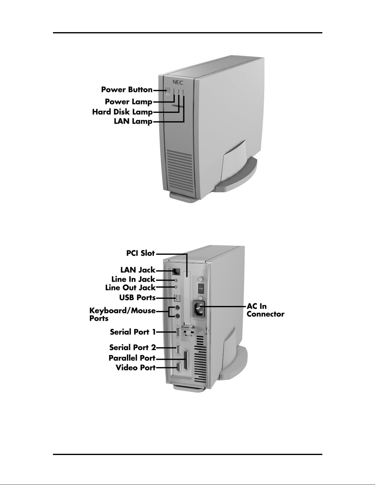
1-2 Technical Information
Figure 1-1 PowerMate NetPC Features – Front View
Figure 1-2 PowerMate NetPC Features – Back View
Page 19
Technical Information 1-3
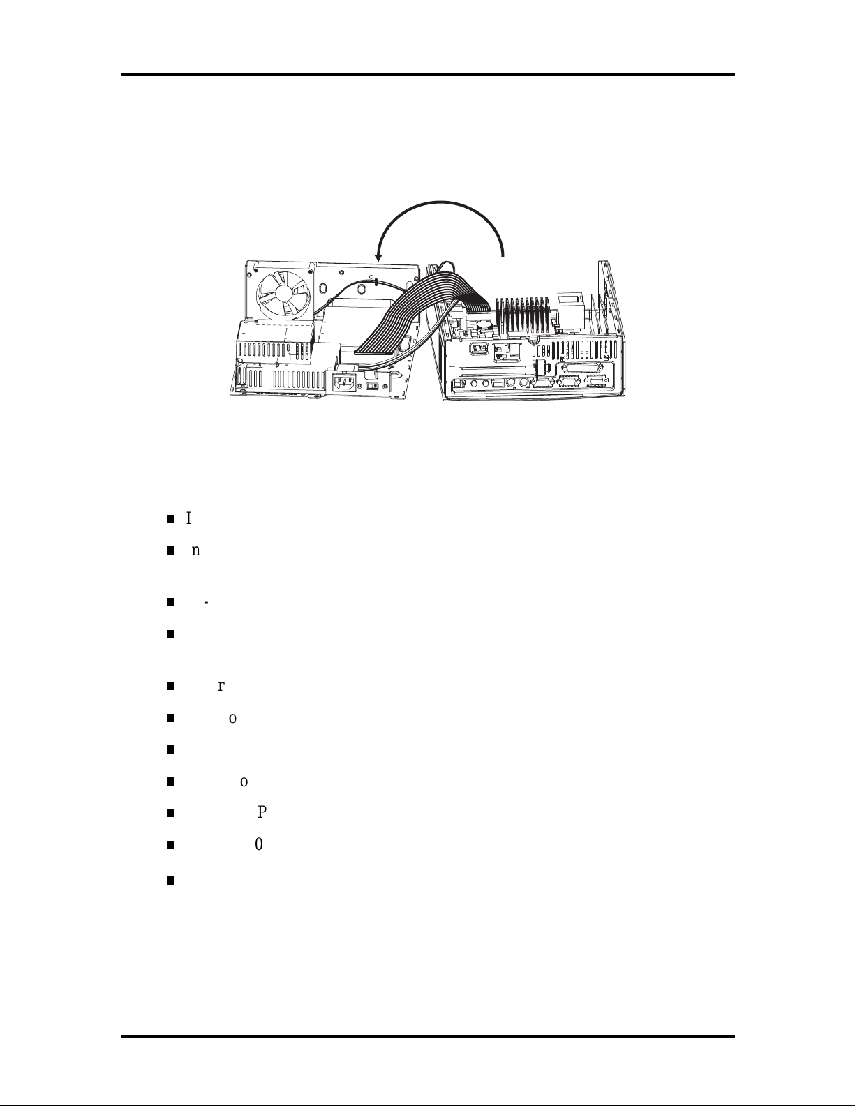
The NetPC chassis is divided into two sheet-metal halves. This allows the box to be
completely enclosed and “sealed” before plastics are installed on the outside. The top half of
the system contains the hard disk, fan, and power supply. The bottom half contains the
system board and riser card.
Figure 1-3 Top and Bottom Chassis Assemblies
The basic hardware features inside the PowerMate NetPC are listed below:
Intel CN430TX system board
Intel Pentium 166-MHz MMX processor
Intel Pentium 200-MHz MMX processor
RJ-45 LAN connector (on riser card) for connection to an Ethernet network
Two 168-pin DIMM sockets; system memory from 16 MB using 16-MB, 32-MB,
and (per availability) 64-MB or 128-MB sticks; upgradeable to 256 MB
S3 Trio 64 ViRGE/GX graphics chip integrated on system board
2 MB of video SDRAM
256-KB pipeline burst cache memory
2.0-GB or 3.2-GB hard disk drive
Yamaha OPL3-SA3 sound system integrated on system board
Chicony 104 keyboard
Microsoft IntelliMouse.
Page 20
1-4 Technical Information
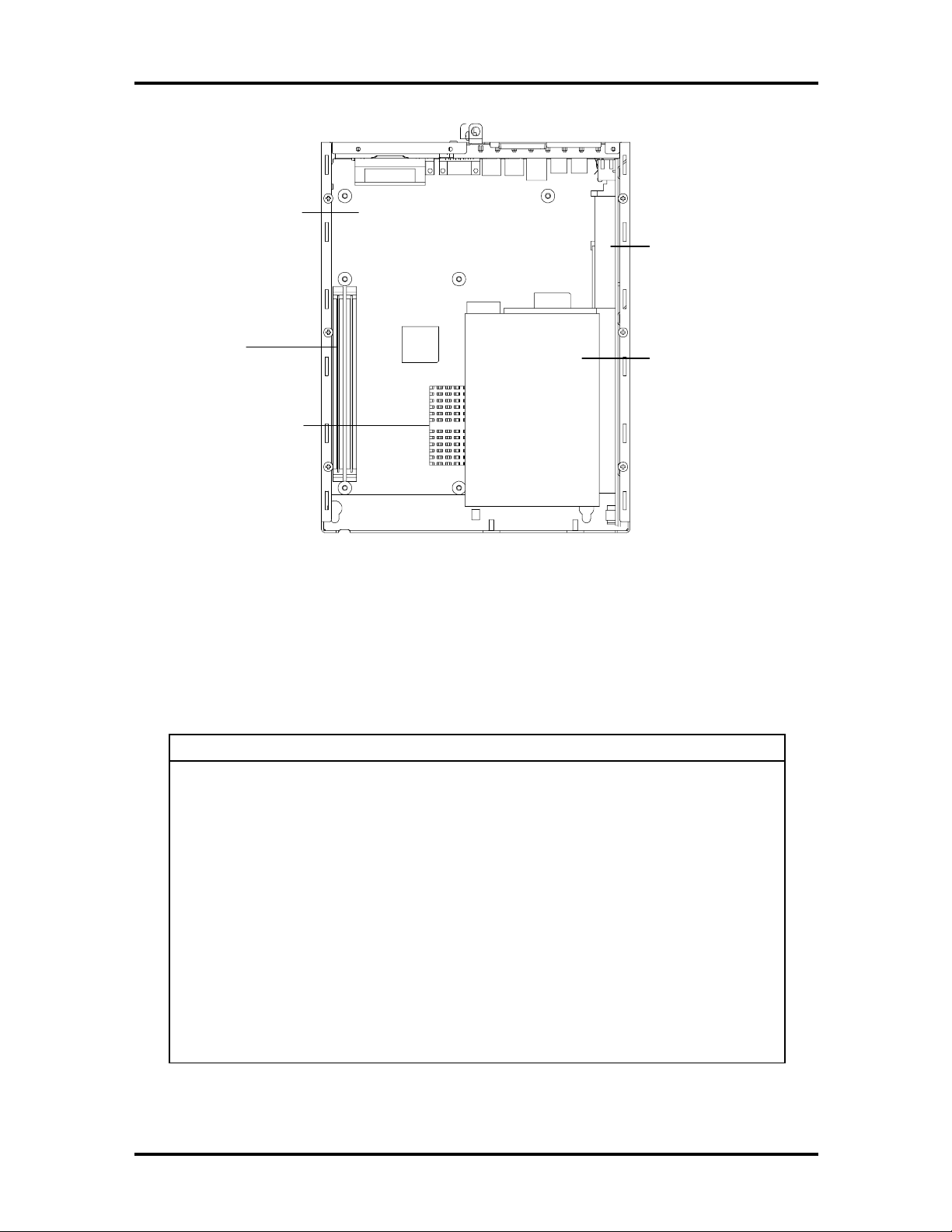
System Board
DIMM
Sockets
Processor/Heatsink
Riser Card
Hard Disk
Figure 1-4 Chassis Hardware Features
PowerMate NetPC computers are configured according to Table 1-1.
Table 1-1 PowerMate NetPC System Configuration
Component Description
System Unit
System Board Intel CN430TX (with sound)
CPU* Pentium 166-MHz MMX
System RAM* 16 MB to 256 MB of SDRAM in 2 DIMM sockets
IDE Hard Disk
Drive*
Pentium 200-MHz MMX
Western Digital Ultra DMA/33:
2.0 GB (WDAC22000)
3.2 GB (WDAC33200)
L2 Cache 256-KB
Graphics S3 Trio 64 ViRGE/GX 3D Graphics on system board
Video DRAM 2 MB of SGRAM soldered on system board
* Varies by system
Page 21
Table 1-1 PowerMate NetPC System Configuration
Component Description
Audio Yamaha OPL3-SA3
Power Supply Astec 51-watt (rated)
Technical Information 1-5
Keyboard
Mouse
“Melted” Chicony KB8963
Microsoft IntelliMouse 68874
SYSTEM BOARD
The system board includes the following features:
Intel 82430TX PCI chipset used for PCI/ISA, memory, and peripheral control
PC87307 Super I/O controller (integrates standard PC I/O functions: two serial
ports, one EPP/ECP-capable parallel port, floppy disk interface, real time clock,
and keyboard and mouse controller; support for two USB interfaces)
Two dual in-line memory module (DIMM) sockets with support for up to
256 MB of SDRAM using DIMMs
PTL BIOS in a flash memory device supporting system setup and PCI auto-
configuration; the NetPC BIOS is slightly different than the standard PC BIOS
(boot from CD-ROM is not an option, since this device is not integrated into the
system).
Expansion slot for riser card
PS/2®-style keyboard and mouse connectors
32-KB internal dual write-back cache integrated on the MMX processor
Pipelined 32-bit addressing
64-bit data bus
from 16 MB to 256 MB of SDRAM upgradeable with 4-MB, 8-MB, 16-MB,
32-MB, 64-MB or 128-MB increments through DIMM sockets on system board
(64-MB and 128-MB as available)
256-KB asynchronous write-back secondary cache memory
System Setup program built into the BIOS
2-Mb Flash ROM for fast economical BIOS upgrades
PCI local bus for fast data transfer
Support for Intel Pentium processor upgrade
Page 22

1-6 Technical Information
National Heceta LM78 chip for monitoring voltage, temperature, and security
Integrated sound
OPTi Sound Blaster PRO, OPTi Sound Blaster 2.0, and Microsoft
Windows Sound System compatible
SRS 3D sound logic
Built-in 16-bit Sigma-Delta stereo CODEC and FM synthesis
One intelligent drive electronics (IDE) interface channel
Support for Ultra DMA/33 on Windows 95 systems
Support for two IDE devices on the channel, one set as master, the other as
slave (physically, only one hard disk fits in the chassis)
NOTE:
DMA/33 device on the IDE channel. If an
additional IDE device is added to the IDE
channel, neither device can use Ultra DMA/33
mode.
The system supports only one Ultra
Power management with power saving mode, featuring inactivity timer
External connectors for connecting the following external devices:
VGA-compatible monitor (standard, super, high-resolution VGA)
Personal system/2 (PS/2®)-style mouse
PS/2-style keyboard
Parallel printer; parallel port includes bi-directional Enhanced Parallel Port
(EPP) and Enhanced Capabilities Port (ECP) support
Serial devices through two buffered 16C550 UART serial ports, supporting
up to 115.2 KB per second (only one port enabled)
Two USB devices
Multimedia speaker and microphone.
Page 23

Technical Information 1-7
y
y sy
y
y
g
y
g
Table 1-2 lists the major chips on the system board. See Appendix A, “Connector Pin
Assignments,” for a list of the system board connectors. See Appendix B, “Jumper
Settings,” for a description of board switches.
Table 1-2 System Board Feature Components
Chip Function
Pentium Chip 166-MHz MMX Pentium processor
200-MHz MMX Pentium processor
82430TX Chipset:
430TX S
430TC PCI ISA IDE Xcelerator
(PIIX4)
National Heceta LM78 Provides voltage, temperature, and securit
PC87307VUL I/O Controller Multimode parallel port:
stem Controller (MTXC)
Provides CPU interface control, functions as
L2 write-back cache controller; DRAM
controller; full
latenc
management control.
Functions as a PCI to ISA bridge; PCI IDE
functionalit
dual channel enhanced IDE interface with
support for Ultra DMA/33; enhanced DMA
controller; and interrupt controller based on
82C95, with support for 15 interrupts; power
mana
counters.
monitoring.
Centronics compatible (standard mode)
Enhanced capabilities port (ECP)
Enhanced parallel port (EPP)
Two RS-232C serial ports
Inte
Supports industry-standard floppy controller
PCI bus interface; power
ement control; real-time clock; 16-bit
rated 8042A keyboard controller
nchronous minimum
, a USB controller; integrated
Yamaha OPL3-SA3 Audio on system board
S3 Trio 64 ViRGE/GX 3D graphics on system board
Processor and Secondary Cache
The system uses an Intel Pentium processor with an internal clock speed of 166 MHz,
or 200 MHz. These processors use Intel MMX technology.
The processor is an advanced pipelined 32-bit addressing, 64-bit data processor designed to
optimize multitasking operating systems. The 64-bit registers and data paths support 64-bit
addresses and data types.
Page 24

1-8 Technical Information
The MMX processor has 32 KB of built-in cache memory (16 KB instruction and 16 KB
data). To use the Pentium processor’s power, the system features an optimized 64-bit
memory interface and 256 KB of secondary write-back cache located on the system board.
The processor is compatible with 8-, 16-, and 32-bit software written for the Intel386™,
Intel486™, Pentium, and Pentium Pro processors. The Pentium processor is mounted into a
socket-7 zero insertion force (ZIF) socket. Systems with the 166-MHz processor can be
upgraded to 200-MHz. The socket provides an easy upgrade path.
System BIOS
The system BIOS is from Intel, based on Phoenix Technologies Limited (PTL) BIOS ‘95.
This ISA- and PCI-compatible BIOS is contained in a flash memory device on the system
board. The BIOS provides the Power-On Self-Test (POST), the system Setup program, a
PCI and IDE auto-configuration utility, and BIOS recovery code.
The system BIOS is always shadowed. Shadowing allows any BIOS routine to be executed
from fast 32-bit DRAM on the system board, instead of from the slower 8-bit flash device.
NEC’s Flash ROM allows fast, economical BIOS upgrades. The Flash ROM is a
reprogrammable EPROM containing both the system and video BIOS. Using the Flash
ROM to change the ROM BIOS provides the following advantages:
the BIOS upgrade is performed quickly and easily
the expense of replacing ROM BIOS chips is eliminated, so system maintenance
costs are reduced
there is less chance of inadvertently damaging the system board than when
physically replacing ROMs
new technology can be incorporated while maintaining corporate standards
network administrators can exercise company-wide control of BIOS revisions.
Page 25

Technical Information 1-9
The BIOS programs execute the Power-On Self-Test, initialize processor controllers, and
interact with the display, diskette drives, hard disk drives, communication devices, and
peripherals. The system BIOS also contains the Setup utility. The POST copies the ROM
BIOS into RAM (shadowing) for maximum performance.
The Flash ROM allows the system and video BIOS to be upgraded with the BIOS Update
utility, without having to physically remove the ROM (see Section 2 for further information
on the BIOS Update utility). The Flash ROM supports the reprogramming of the system
BIOS and the video BIOS.
The system memory map is shown in Table 1-3.
Table 1-3 System Memory Map
Memory Space Size Function
100000-10000000 256 MB Extended memory
F0000-FFFFF 64 KB PTL system BIOS
EC000-EFFFF 16 KB Reserved for BIOS
EA000-EBFFF 8 KB ECSD (Plug and Play configuration and DMI)
E9000-E9FFF 4 KB Reserved for BIOS
E8000-E8FFF 4 KB OEM logo or Scan User Flash
E4000-E7FFF 32 KB Reserved for BIOS (currently available as UMB)
E0000-E3FFF 96 KB USB buffer area
C8000-D7FFF 160 KB Available HI DOS memory (open to ISA and PCI bus)
A0000-C7FFF 1 KB Video memory and BIOS
9F800-9FFFF 127 KB Extended BIOS data (moveable by memory manager
software)
80000-9F7FF 126 KB Extended conventional memory
00000-7FFFF 512 KB Conventional memory
Page 26

1-10 Technical Information
y
I/O Addressing
The processor communicates with I/O devices by I/O mapping. The hexadecimal (hex)
addresses of I/O devices are listed in Table 1-4. (In Plug and Play systems, these addresses
are typical but may vary by configuration.)
Table 1-4 I/O Address Map
Address (Hex) I/O Device Name
0000-000F DMA controller
0020-0021 Programmable interrupt controller
0040-0043 System timer 1
0060 Standard 101/102 or Microsoft® Natural
Keyboard
0061 System speaker
0064 Standard 101/102 or Microsoft® Natural
Keyboard
0071 System CMOS/real time clock
0078-007F System board resources
0080 System board resources
0081-008F DMA controller
00A0-00A1 Programmable interrupt controller
00C0-00DF DMA controller
00F0-00FF Numeric data processor
01F0-01F7 Intel 82371AB PCI Bus Master IDE controller
01F0-01F7 Primary IDE controller (dual FIFO)
0220-022F YAMAHA OPL3-SAx Sound System
0274-0277 I/O read data port for ISA Plug and Pla
enumerator
0290-0297 System board resources
0278-027F Parallel port 2
02E8-02EF COM4
02F8-02FF COM2
0330-0331 YAMAHA OPL3-SAx Sound System
0370-0371 YAMAHA OPL3-SAx Sound System
0378-037F Parallel port (LPT1)
0388-038F YAMAHA OPL3-SAx Sound System
003B0-03BB S3 Virge/DX/GX PCI graphics
Page 27

Technical Information 1-11
Table 1-4 I/O Address Map
Address (Hex) I/O Device Name
003C0-03DF S3 Virge/DX/GX PCI graphics
03F0-03F5 Standard diskette drive controller
03F6 Intel 82371AB PCI Bus Master IDE controller
03F6 Primary IDE controller (dual FIFO)
03F7 Standard diskette drive controller
04D0-04D1 System board resources
0530-0537 YAMAHA OPL3-SAx Sound System
0CF8-0CFF PCI bus
7000-700F System board resources
8000-803F System board resources
FCA0-FCBF Intel 82371AB PCI Bus Master IDE controller
FCD0-FCD7 Intel 82371AB PCI Bus Master IDE controller
FCD0-FCD7 Primary IDE controller (dual FIFO)
FCE0-FCFF Intel EtherExpress Pro/100 WfM PCI adapter
System Memory
The system comes with between 16 MB and 256 MB of SDRAM installed in dual in-line
memory module DIMM sockets on the system board.
The memory configuration consists of two sockets. The DIMM memory sockets accept
168-pin, 64-bit (non-parity) 8-, 16-, 32-, 64-, and 128-MB DIMMs. Table 1-5 lists the
supported DIMMs.
Table 1-5 Memory Configurations
DIMM Size Type Configuration Technology
8 MB CAS Latency 2 SDRAM 1-Mbit x 64-bit 16 Mbit
16 MB CAS Latency 2 SDRAM 2-Mbit x 64-bit 16 Mbit
32 MB CAS Latency 2 SDRAM 4-Mbit x 64-bit 16 Mbit
64 MB CAS Latency 2 SDRAM 8-Mbit x 64-bit 64 Mbit
128 MB CAS Latency 2 SDRAM 16-Mbit x 64-bit 64 Mbit
Page 28

1-12 Technical Information
Memory upgrades are easy with DIMMs. Advantages of using DIMMs are listed below:
DIMMs do not need to be installed in pairs on the system board.
DIMMs of different memory types and sizes can be installed on the same board.
No switches or jumpers need to be set if the memory is changed.
The system BIOS automatically detects the DIMMs.
See “Checking the Memory in the System” in Section 3 for the valid DIMM configurations.
Hardware Monitor
The National Semiconductor Heceta LM78 chip provides economical instrumentation
capabilities (NEC MagicEye™ Technology) for reduced cost of PC ownership when the
system is used with the LANDesk® Client Manager. This single-chip ASIC features:
integrated ambient temperature sensor
power supply voltage monitoring to detect excessively high or low voltage levels
registers for storing POST hardware test results and error codes
remote reset capabilities from a remote peer or server through LANDesk Client
Manager v.3.0
When ranges for temperature, fan speed, or voltage are exceeded, an interrupt is activated.
The hardware monitor component connects to the ISA bus as a 8-bit I/O mapped device.
Interrupt Controller
The interrupt controller operates as an interrupt manager for the entire system environment.
The controller:
accepts requests from peripherals
issues interrupt requests to the processor
resolves interrupt priorities
provides vectors for the processor to determine which interrupt routine to
execute.
The interrupt controller has priority assignment modes that can be reconfigured at any time
during system operations.
The interrupt levels are described in Table 1-6. Interrupt level assignments 0 through 15 are
in order of decreasing priority. See Section 2 for information on using the Setup utility to
change the interrupts.
Page 29

Table 1-6 Interrupt Level Assignments*
g
Interrupt Assignment*
Technical Information 1-13
Windows 95 System
Windows NT 4.0 System
0 System Timer System Timer
1 Keyboard Keyboard
2 Sound Sound
3 Not used Not used
4 Serial Port A - COM1 Serial Port A - COM1
5 OPL3-SA
X
OPL3-SA
X
6 Floppy Disk Floppy Disk
7 Parallel Port - LPT1 OPL3-SA
X
8 RTC Clock/Calendar RTC Clock/Calendar
9 S3 Virge/DX/GX
PCI/Intel 82371AB USB
S3 Vir
82371AB USB Serial Port
e/DX/GX PCI/Intel
Serial Port
10 Not used Not used
11 Intel Ether Express
Pro/100 PCI
Intel Ether Express Pro/100
PCI
12 Mouse Mouse
13 Coprocessor Coprocessor
14 IDE port A IDE port A
15 NA NA
* In Plug and Play systems, these interrupts are typical but may vary by
configuration. See the following paragraphs.
Page 30

1-14 Technical Information
DMA settings are given in Table 1-7.
Table 1-7 DMA Settings*
DMA
0 OPL3-Sax OPL3-Sax
1 OPL3-Sax OPL3-Sax
2 Floppy Disk Controller Floppy Disk Controller
3 Available Available
4 Cascade Cascade
5 Available Available
6 Available Available
7 Available Available
* In Plug and Play systems, these interrupts are typical but may vary by
configuration. See the following paragraphs.
Windows 95 System Windows NT 4.0 System
The following audio resources vary depending on which operating system or environment
they run under (default based on shipping configurations):
Base I/O address: 220-22f
FM Synthesis address: 388-38B
MPU-401 MIDI address: 330-331
The following information indicates the possible resources that a sound component can
have after third party devices have been added to the system:
Joystick address: 201
Base address: 220 to 250
FM Synthesis address: 388
MPU-401 MIDI address: 330
Audio DMA: 0, 1, 3
Audio IRQ: 5, 7, 9, 10
MPU-401 MIDI IRQ: 5, 7, 9, 10
Page 31

Technical Information 1-15
Plug and Play
The system comes with a Plug and Play BIOS in support of Plug and Play technology. Plug
and Play simplifies setup procedures for installing Plug and Play expansion boards. With
Plug and Play, adding a Plug and Play expansion board is done by turning off the system,
installing the board, and turning on the system. There are no jumpers to set and no system
resource conflicts to resolve. Plug and Play automatically configures the board. (Some Plug
and Play devices may need to be jumpered if used in a system running the Windows NT
operating system.)
Chassis
The NetPC chassis is divided into two sheet-metal halves. The system has one 3.5-inch
drive slot for a hard drive and one add-in card slot, which accepts a half-length PCI card.
The dimensions of the chassis are included in Table 1-16.
Power connections to the system board are carried through the riser card, which also
contains the half-length PCI card slot.
PCI Local Bus
The 32-bit PCI bus is the primary I/O bus for the system. The PCI bus is a highly-integrated
I/O interface that offers the highest performance local bus available for the Pentium
processor. The bus supports burst modes that send large chunks of data across the bus,
allowing fast displays of high-resolution images.
The PCI bus operates at half the Pentium processor’s bus speed. The PCI bus supports
memory transfer rates of up to 105 MB per second for reads and up to 120 MB per second
for writes, depending on processor configuration.
The high-bandwidth PCI bus eliminates the data bottleneck found in traditional systems,
maintains maximum performance at high clock speeds, and provides a clear upgrade path to
future technologies.
PCI expansion slot connector pin assignments are provided in Appendix A.
Page 32

1-16 Technical Information
PCI/IDE Ports
The system board supports one high-performance PCI/IDE port (the primary channel for a
master/slave configuration), though the port is actually located on the riser card. The port
supports one or two devices in a master/slave setting configurable in BIOS Setup. The
primary PCI/IDE port has an enhanced IDE interface that supports PIO Mode 4 devices
with 16 MB per second 32-bit wide data transfers on the high-performance PCI local bus.
The channel supports Ultra DMA/33. The installed hard disk drive is connected to the
primary PCI/IDE port with a two-connector cable. A second Ultra DMA/33 device can be
logically added to the primary PCI/IDE channel, but in such a case, neither device should
run in Ultra DMA/33 mode because the length of the three-connector cable required for this
configuration would cause signal degradation.
NOTE:
Physically, the chassis only has room for
one hard disk drive.
Parallel Interface
The system has a 25-pin bi-directional parallel port on the system board. Port specifications
conform to the IBM-PC standards. The port supports Enhanced Capabilities Port (ECP)
and Enhanced Parallel Port (EPP) modes for devices that require ECP or EPP protocols.
The protocols allow high-speed bi-directional transfer over a parallel port and increase
parallel port functionality by supporting more devices.
The BIOS has automatic ISA printer port sensing that works with most devices. If the
BIOS detects an ISA printer port mapped to the same address, the built-in printer port is
disabled. (Verify in the BIOS Setup that printer ports mapped to the same address are
enabled or disabled appropriately.) The BIOS also sets the first parallel interface port it
finds as LPT1 and the second port it finds as LPT2. The interrupt is set at IRQ7 via the
Setup utility. Software-selectable base addresses are 3BCh, 378h, and 278h.
Sets of I/O addresses and interrupts for the parallel port are given in Table 1-8. This is a list
of all possible configurations; the parallel port uses only one set.
Table 1-8 Parallel Port Addresses and Interrupts
Starting I/O Address Interrupt Level Port
378 IRQ05 LPT1
278 IRQ05 LPT2
228 IRQ05 LPT3
378 IRQ07 LPT1
278 IRQ07 LPT2
228 IRQ07 LPT3
Page 33

Technical Information 1-17
NOTE:
parallel port are not available for ISA parallel
ports.
Parallel interface signals are output through the system board 25-pin, D-subconnector. The
connector is located at the rear of the system unit. Pin locations for the parallel interface
connector are given in Appendix A.
Any interrupts used for the built-in
Serial Interface
The system has two 16C550 UART compatible serial ports (COM1 and COM2) integrated
on the I/O controller. The serial ports support the standard RS-232C interface. The buffered
high-speed serial ports support transfer rates up to 115.2 KB. These ports allow the
installation of high-speed serial devices for faster data transfer rates.
Sets of I/O addresses and interrupt levels for the two channels are given in Table 1-9 and
Table 1-10. (Note that COM2 is disabled by default.) The interrupt levels are selectable via
the Setup utility and include IRQ3 and IRQ4. Software selectable base addresses are 3F8h,
2F8h, 3E8h, and 2E8h. If serial ports are reconfigured to share an interrupt, verify that the
software and hardware added by users can share interrupts without problems.
Page 34

1-18 Technical Information
NOTE:
serial ports are not available for ISA parallel
ports.
If serial ports share an interrupt, verify that
hardware and software added to the system can
share these interrupts without problems.
Table 1-9 Serial Port 1 Addresses and Interrupts
Starting I/O Address Interrupt Level Port
3F8 IRQ04 COM1
3F8 IRQ03 COM1
3E8 IRQ04 COM3
3E8 IRQ03 COM3
Any interrupts used for the built-in
Table 1-10 Serial Port 2 Addresses and Interrupts
Starting I/O Address Interrupt Level Port
3F8 IRQ04 COM1
2F8 IRQ03 COM2
3E8 IRQ04 COM3
3F8 IRQ03 COM1
2F8 IRQ04 COM2
3E8 IRQ03 COM3
See Section 2, “Setup and Operation,” for information on resetting the port through the
Setup utility.
Serial interface specifications include:
Baud rate up to 115.2 KB per second
Word length 5, 6, 7, or 8 bits
Stop bit 1, 1.5, or 2 bits
Start bit 1 bit
Parity bit 1 bit (odd parity or even parity).
Page 35

Technical Information 1-19
Serial interface signals are output through the system board 9-pin, D-subconnectors. The
connectors are located at the rear of the system unit. Pin locations for the serial interface
connector are shown in Appendix A.
USB Interface
The Universal Serial Bus (USB) ports allow new Plug and Play serial devices to be added
without having to open the system. The devices may be plugged into a USB port. The USB
determines system resources for each peripheral and assigns them without user intervention.
With a hub and the proper cabling, up to 127 devices can be daisy chained to a single
computer. Boot support for a USB keyboard is present so the system can be booted with a
USB keyboard instead of a standard keyboard.
Video Interface
The system board features the S3 Trio 64 ViRGE/GX 3D accelerator chip with 2 MB of
video SGRAM soldered on the system board.
The video and graphics controller accelerates color space conversion and video upscaling to
deliver exceptional graphics and high quality MPEG and video playback and true
multimedia functionality. MPEG is a compression/decompression standard developed by a
professional video group called the Motion Picture Experts Group. MPEG produces fullscreen, 30-frames-per-second, broadcast-quality digital video.
The graphics accelerator chip provides:
Outstanding TV-quality video playback
Accelerated multimedia and application performance
Brilliant true color graphics
Razor-sharp photo-realistic images
Ultra-fast game action
Texture mapping performance for 3D games, 3D Web browsing, 3D
presentations, and other 3D applications.
Page 36

1-20 Technical Information
The default video mode is 800 by 600 pixels with 256 colors. The system also supports the
resolutions, colors, and refresh rates listed in Table 1-11.
Table 1-11 Supported Resolutions, Colors, and Refresh Rates
Refresh Rate (Hz)
2-MB Memory
Resolution (pixels)
1600 x 1200 48.5*,60
1280 x 1024 43*,60,75,80 43*,60,75,85
1024 x 768 43*,60,70,75,85 43*,60,70,75,85 43*,60,70,75,85
800 x 600 56,60,72,75,85 56,60,72,75,85 56,60,72,75,85 56,60,72,75,85
640 x 480 60 60,70,72,75,85 60,72,75,85 60,72,75,85
* Interlaced
4-Bit Color
(16 colors)
8-Bit Color
(256 colors)
15/16-Bit Color
(32K/64K colors)
24-Bit Color
(16M colors)
To take full advantage of the computer’s installed video board and extended graphics, use
the video driver that comes preinstalled on the system.
Integrated Audio
To support the increasing number of multimedia applications, a Yamaha OPL3-SA3 chip is
integrated on the system board. The chip provides 16-bit stereo, Sound Blaster Pro-
compatible audio. System boards with audio provide a line out jack and microphone jack.
The sound system provides all the digital and analog mixing functions required for playing
and recording audio on personal computers. Features include stereo analog-to-digital and
digital-to-analog converters, analog mixing, anti-aliasing and reconstruction filters, line and
microphone level inputs, digital audio compression, and full digital control of all mixer and
volume control functions.
The sound system is standard and features the following:
Yamaha OPL3-SA3 chip integrated on system board
digital audio and analog mixing functions, including stereo analog-to-digital and
digital-to-analog converters, analog mixing, anti-aliasing and reconstruction
filters, line and microphone level inputs, digital audio compression, and full digital
control of mixer and volume control functions
Adlib, Sound Blaster Pro 2.0, Windows Sound System, and MPU-401
compatibility.
Page 37

Technical Information 1-21
The Yamaha OPL3-SA3 includes a full Plug and Play interface. Each logical device is
configured into the host environment using the Plug and Play configuration methodologies.
The audio subsystem requires two DMA channels and one interrupt.
DISKETTE DRIVE SUPPORT
A diskette drive is not included in the system. However, the riser card contains a diskette
drive connector and controller. A diskette drive with its own power source can be
connected by a ribbon cable to the diskette drive connector on the riser card. You must
enable the diskette drive controller in BIOS Setup to use a diskette drive in the NetPC
system (see “Setup Utility” in Section 2).
HARD DISK DRIVE
All systems ship with one internal 3 1/2-inch hard disk drive (1-inch high, thin-height)
installed in the internal drive slot in the top half of the chassis. Drives are available in
2.0-GB and 3.2-GB Western Digital models.
A two-connector hard disk drive IDE cable connects to the hard disk and the primary
connector on the riser card. The riser card has one IDE/PCI interface connector (primary
only) for connecting IDE storage devices such as hard disk drives. Logically, the connector
supports up to two IDE devices. Physically, there is room for one hard disk in the chassis.
An optional second hard disk drive can be added to the primary channel if the cable is
replaced with a three-connector IDE cable. If an additional hard disk drive is added to the
primary IDE channel, configure both devices as non-Ultra DMA.
Use the “Storage Device Installation” procedures in Section 3 when replacing the hard disk.
Connector locations are given in Appendix A. Jumper settings are given in Appendix B.
Hard disk drive specifications are given in Table 1-17 and Table 1-18.
POWER SUPPLY
The power supply is mounted inside the top chassis. It supplies power to the system board,
option board, hard disk, keyboard, and mouse. A fan inside the chassis provides system
ventilation. The power supply provides 51 watts (rated). Connector locations are given in
Appendix A.
The power supply connector differs from the standard NLX and ATX power supply
connectors. Pin 18 of the PowerMate NetPC power supply is used for thermal fan speed
control and not for -5V.
WARNING:
ATX power supply to operate the NetPC system,
as this will cause the fan circuit to fail.
Do not use a standard NLX or
Page 38

1-22 Technical Information
The power supply supports remote power on/off. This means that the system board and
riser card can turn off the system power through software control. Pin 14 of the power
supply connector lets the system board recognize a power supply that supports this “softoff” feature.
To enable soft-off control in software, power management (PM) must be enabled in the
operating system. When the system BIOS receives the correct PM command from the
operating system, the BIOS turns off power to the computer. For example, in the Windows
95 Start menu, the user selects Shutdown to turn off the power.
Depending on how “Restore On AC/Power Loss” is configured in the Setup utility (see
“Boot Menu” in Section 2), if power to the computer is interrupted by a power outage or a
disconnected power cord, when power resumes, the computer returns to the state it was in
before the power interruption. The default CMOS setting for a power loss is “Last State.”
RISER CARD
The riser card serves as an interface between the system board and the network and
between the system board and any installed PCI expansion board. The riser card contains an
RJ-45-compatible LAN connector for connecting the system to an Ethernet network. The
card also contains a PCI expansion slot for installing a half-length PCI expansion board. The
riser card connects to the system board through a 170-pin edge connector and also
cable-connects to the power supply to provide DC power to the NetPC system components.
The riser card contains one primary IDE connector for the system’s hard disk and also
contains a diskette drive connector. For more information on riser card features, see
Table 1-21. Connector pin assignments for the riser card are provided in Appendix B.
MOUSE
A Microsoft IntelliMouse is standard equipment for the system. This PS/2-compatible
mouse has two buttons and a cursor control button. The mouse has a self-cleaning
mechanism that prevents a buildup of dust or lint around the mouse ball and tracking
mechanism. The six-pin mouse cable connector plugs into the rear of the system. Mouse
specifications are given in Table 1-14.
KEYBOARD
The PS/2-compatible keyboard is standard equipment for the system. The keyboard
provides a numeric keypad, separate cursor control keys, 12 function keys, and is capable of
up to 48 functions. Key status lamps on the keyboard include Num (Numeric) Lock, Caps
(Capital) Lock, and Scroll Lock. The keyboard’s six-pin connector plugs into the rear of the
system. Keyboard specifications are given in Table 1-15.
Page 39

Technical Information 1-23
g
y
y
y
y
y
SPECIFICATIONS
System specifications are found in Table 1-12 through Table 1-21.
Table 1-12 System Board Specifications
Feature Specification
System Board Intel CN430TX with integrated audio
Processor Pentium 166 MHz MMX, 200 MHz MMX
Cache Memory 32 KB of primary cache (16-KB data, 16-KB instruction)
inte
256 KB of secondary cache system board
Flash ROM 2 Mb Flash ROM
Chip Set Intel 82430TX PCI chipset
I/O Controller PC87307 Super I/O controller
System Memory From 16 MB to 256 MB in two DIMM sockets on system
board
rated in the processor
Optional DIMMs 16-MB, 32-MB, 64-MB (as available), and 128-MB (as
available); 168-pin, 64-bit non-parity DIMMs
Video Accelerator S3 ViRGE 2D/3D video/graphics accelerator
170-MHz RAMDAC, and clock s
a single chip
S3 Streams Processor technology for video playback
Graphics Support
1280 by 1024 pixels, up to 256 colors
1024 b
800 b
640 by 480 pixels, up to 16M colors
Text
80 columns b
132 columns b
132 columns by 43 lines
Video Memory
Audio Chip Yamaha OPL3-SA3
Battery Replaceable coin type battery
Video Memory
768 pixels, up to 64K colors
600 pixels, up to 16M colors
25 lines
25 lines
2 MB of video SGRAM
nthesizer integrated in
Page 40

1-24 Technical Information
g
y
y
g
g
Table 1-13 General Specifications
Feature Specification
Recommended Operatin
Environment
Administrative Compliance UL 1950 - safet
Temperature: 50°F to 95°F (10°C to 35°C)
Relative Humidity: 20% to 80%
CSA C22.2 No. 950-m89
TUV EN60950: 1988
FCC part 15, Subpart J, Class B - emissions
FCC part 68
IEC 950 - safet
VDE 0871/6.78, Class B - emissions
Table 1-14 Mouse Specifications
Feature Specification
Mouse Microsoft IntelliMouse
Features 2-button with cursor movement wheel
X & Y encoder resolution: 400 PPI opto-mechanical
Wheel Resolution: zoom resolution 18 counts per
revolution
Operating Characteristics
Vin = 115 V or 230 V as appropriate Ta = 25
°
Thermal stabilization - 1 hour minimum
Physical Features Length: 4.53 inches
Width at head: 2.25 inches
Width at hips: 2.6 inches
ht: 1.52 inches
Hei
Weight: 170 grams +/1 20 grams
Temperature Range
Operatin
Storage: -20° to 60° C
: 5° to 35° C
Table 1-15 Keyboard Specifications
Feature Specification
Keyboard Chicony KB-6923
Dimensions Width: 19.0 inches (48.3 cm)
Depth: 8.4 inches (21.3 cm)
Height: 1.6 inches (4.1 cm)
Weight 3.5 to 4.0 lb. (1.6 to 1.8 kg)
Page 41

Technical Information 1-25
y
y
y
y
Table 1-16 System Unit Specifications
Feature Specification
Dimensions Width (horizontal): 9.5 in (241 mm)
Depth: 12.5 in (318 mm)
Height (horizontal): 3.5 in (89 mm)
Weight Approximately 13.5 lb. (6.14 kg), dependent upon options
Expansion Board Slots One 32-bit PCI slot
Peripheral Interface (rear panel) RJ-45 LAN connector
PS/2-st
PS/2-st
Two RS-232C serial ports
Parallel printer port
VGA monitor port
Two universal serial bus ports
Two audio connectors (line in, line out)
Front Panel Power button
Power/Suspend state indicator lamp
Hard disk drive bus
LAN activity lamp
le keyboard connector
le mouse connector
indicator lamp
Table 1-17 2.0-GB Hard Disk Drive Specifications
Feature Specification
Hard Disk Drive 2.0-GB Western Digital Caviar™ (WDAC22000-LLA)
Physical Configuration
Formatted Capacit
Number of Disks
Data Surfaces
Number of R/W Heads
Maximum Data Rate from
Media
Bytes per Sector 512 (default)
Setup Geometry of Drive 3876 cyl x 16 heads x 3,907,008 sectors
Servo Type Embedded
Recording Method GCR 8,9 PRML
2000 MB
2
3
3
114 Mbps (Megabits per second)
Page 42

1-26 Technical Information
g
g
Table 1-17 2.0-GB Hard Disk Drive Specifications
Feature Specification
Performance
Track to Track Seek
(typical)
Average Seek,
Read/Write
Maximum Seek,
Read/Write
Average Latency 5.8 ms
Rotation Speed 5200 RPM
Data Transfer Rate
Buffer to Disk (Mbits/s) 114 max
Buffer to Host
(Mbytes/s)
Interleave 1: 1
Buffer Size 256 Kbytes
Power on to Ready (typical) 11 sec
Power on to Ready (max) 18 sec
Spindle Stop Time (typical) 6 sec
Start/Stop Cycles
(minimum)
3.0 ms
11.5/13.5 ms
15.0/17.0 ms
16.6 max
40,000
MTBF 350,000 hours
MTTR 10 minutes
Data Reliability < 1 unrecoverable error per 1013 bits read
Actuator Rotary voice coil
Interface 40-pin EIDE bus connector
Temperature (non-condensing)
Humidity (non-condensing)
Atmospheric Pressure (Altitude) Operating: -1000 to 10,000 ft. (-300 to 3000 meters)
Dimensions Height:1.0 inches (25.4 mm)
Operatin
Non-operating: -40° to 60°C (-40° to 138°F)
Operatin
Non-operating: 5% to 95% rh, 33°C (94.6°F)
Non-operating: -1000 to 40,000 ft. (-300 to 12,000 meters
Width: 4.0 inches (101.6 mm)
Depth: 5.75 inches (146.1 mm)
Weight: 1.1 LB (0.500 kg)
: 5° to 55° C (41° to 131°F)
: 8% to 80% rh, 33°C (94.6°F)
Page 43

Technical Information 1-27
y
Table 1-18 3.2-GB Hard Disk Drive Specifications
Feature Specification
Hard Disk Drive 3.2-GB Western Digital Caviar (WDAC33200-00LA)
Physical Configuration
Formatted Capacit
Number of Disks
Data Surfaces
Number of R/W Heads
Maximum Data Rate from
Media
Bytes per Sector 512 (default)
Setup Geometry of Drive 6296 cyl x 16 heads x 6,346,368 sectors
Servo Type Embedded
Recording Method GCR 8,9 PRML
Performance
Track to Track Seek
(typical)
Average Seek,
Read/Write
Maximum Seek,
Read/Write
Average Latency 5.8 ms
Rotation Speed 5200 RPM
3249 MB
3
5
5
114 Mbps (Megabits per second)
3.0 ms
11.5/13.5 ms
15.0/17.0 ms
Data Transfer Rate
Buffer to Disk (Mbits/s) 114 max
Buffer to Host
(Mbytes/s)
Interleave 1: 1
Buffer Size 256 Kbytes
Power on to Ready (typical) 11 sec
Power on to Ready (max) 18 sec
Spindle Stop Time (typical) 6 sec
Start/Stop Cycles
(minimum)
MTBF 350,000 hours
MTTR 10 minutes
Data Reliability < 1 unrecoverable error per 1013 bits read
16.6 max
40,000
Page 44

1-28 Technical Information
g
g
g
g
2
g
2
g
g
2
g
2
Table 1-18 3.2-GB Hard Disk Drive Specifications
Feature Specification
Actuator Rotary voice coil
Interface 40-pin EIDE bus connector
Temperature (non-condensing)
Operatin
: 5° to 55° C (41° to 131°F)
Non-operating: -40° to 60°C (-40° to 138°F)
Humidity (non-condensing)
Operatin
: 8% to 80% rh, 33°C (94.6°F)
Non-operating: 5% to 95% rh, 33°C (94.6°F)
Atmospheric Pressure (Altitude) Operating: -1000 to 10,000 ft. (-300 to 3000 meters)
Non-operating: -1000 to 40,000 ft. (-300 to 12,000 meters
Dimensions Height:1.0 inches (25.4 mm)
Width: 4.0 inches (101.6 mm)
Depth: 5.75 inches (146.1 mm)
Weight: 1.1 lb (0.500 kg)
Table 1-19 Environmental Standards
Parameter Condition Specification
Temperature
Non-Operating
Operating
Humidity
-40 to +60°C; ∆T ≤ 20°C/hr
+10 to +35°C; ∆T ≤ 10°C/hr
Non-Operating 95% RH @ 25-30°C;
∆
RH ≤ 9%/hr, ∆T ≤ 5°C/hr
Shock
Operating 0.001
0.01 g
Packaged 0.015
0.00015g
Vibration Non-operating 0.001
0.01 g
Packaged 0.015
0.00015g
2
/Hz @ 5 Hz, sloping to 0.01
/Hz from 20 to 500 Hz
2
/Hz from 10 to 40 Hz, sloping to
/Hz @ 40 to 500 Hz
2
/Hz @ 5 Hz, sloping to 0.01
/Hz from 20 to 500 Hz
2
/Hz from 10 to 40 Hz, sloping to
/Hz @ 40 to 500 Hz
ESD, Operating ±1.0 to ±20 kV,
air discharge
2
/Hz @ 20 Hz;
2
/Hz @ 20 Hz;
Page 45

Technical Information 1-29
Table 1-19 Environmental Standards
Parameter Condition Specification
AC Line
Line Volt/Freq. 90-132, 180-264 VAC; 47/63 Hz (switch-selectable)
Source Interrupt Power drop-out of 17ms
Surge 2.0 kV Unidirectional;
3.0 kV Ringwave
Acoustical Noise Bystander
position
(1 meter)
32DBa Suspend
38DBa Idle
Table 1-20 Power Supply Specifications
Feature Specification
Power Supply Form Factor CN430TX Net PC Open Frame
Operating Characteristics
Power 51 Watts (maximum) continuous for support of PFC
Efficiency
AC Line
Line Voltage Frequency 90-132, 180-264 VAC; 47/63 Hz
Source Interrupt Power drop-out of 17 ms
Surge 2.0 kV Unidirectional;
65% at full load
≥
≥ 60% “Energy Star“ efficiency (18 Watts)
3.0 kV Ringwave
Voltage Output Regulation Min
+12 VDC
+5 VDC
+3.3 VDC
± 5%
+ 5%/-4%
±3%
current
(amps)
0.1
1.0
0.0
Max
current
(amps)
1.5
12.0
6.0
Peak
current
(amps)
3
–
–
Page 46

1-30 Technical Information
g
Table 1-21 Riser Card Specifications
Feature Specification
Riser card Intel
Features NLX compatible
Support Intel PRO100B LAN Controller
Support for Ultra DMA
Support for up to 10 MB/second 32-bit transfers on
PCI bus
Support for a total of two IDE devices; 40-pin connector
Support for PIO mode 3 and mode 4
PCI slot for half-len
RJ-45 LAN connector
System board slot
Industry Standard Interface One PCI/IDE connector (for master and slave devices)
Diskette drive connector
Fan connector
th board
Page 47

Section 2
Setup and Operation
This chapter contains information on setting up the PowerMate NetPC system and covers
the following topics:
Site selection
Installation
Startup and shutdown
Setup Utility
Flash Utility
NEC Auto Backup Utility
LANDesk Client Manager
NEC Select Install CD.
WARNING: Hazardous voltage, current, and
energy levels are present inside the computer.
Access to the inside is restricted to qualified,
NECCSD-trained personnel. See Chapter 5 for
servicing and parts information.
SITE SELECTION
The computer is designed to operate reliably in a normal office environment. Make sure the
site is well ventilated, dust free, and away from heat sources. In addition, choose a site
according to the following criteria:
Place the computer on a desktop or other raised, flat surface; do not put the
computer on the floor.
Place the computer near a grounded, three-pronged power outlet.
In the United States and Canada, use a NEMA
5-15R outlet for 100-120 VAC or a NEMA 6-15R outlet for 200-240 VAC.
For other geographic regions, use a three-pronged power outlet applicable for
the electrical code of the region.
Page 48

2-2 Technical Information
Make sure there is enough space around the computer for cooling and adequate
air flow – about 3.93 in. (10 cm) clearance in back, 1.96 in.(5 cm) on each side,
and 3.93 in. (10 cm) in front.
The computer has external vents for cooling and air flow (see the following
figure). To ensure proper cooling of the computer, keep all vents clear of
obstructions.
To ensure adequate air flow and reduce the risk of overheating or fire, use the
stand provided with the system for vertical (“tower”) placement of the
computer.
Figure 2-1 Computer Vents
INSTALLATION
Install the computer according to the following procedures and safety standards:
Check the voltage switch.
Select the system orientation.
Connect cables
Prevent internal access.
Page 49

Technical Information 2-3
WARNING: Do not plug in the computer
power cable until you connect all other external
cables (for example, keyboard, mouse, monitor,
and LAN).
The following sections provide installation guidelines and procedures.
CAUTION: The push-button on/off power
switch on the front panel of the computer does
not turn off the AC power. To remove AC
power from the computer, you must unplug the
AC power cable from the power supply or the
wall outlet.
Checking the Voltage Switch
A 51-watt (rated) power supply is integrated into the computer. The voltage ratings for the
power supply are provided in the following table.
Table 2-1 Power Supply Voltage Rating
Voltage Input Frequency (Hz) Current (Amps)
100-127 60 2
200-240 50 1.25
Before connecting the power cable to the back panel of the computer, make sure that the
voltage selector switch is set to the correct AC line source voltage for your region.
For line voltages between 100 and 127 VAC, set the line voltage selector on the
power supply switch to 115V (115 VAC).
For line voltages between 200 and 240 VAC, set the line voltage selector switch
on the power supply to 230V (230 VAC).
Make sure that the correct voltage (115V or 230V) is visible on the switch (see the
following figure). If necessary, use a flat-head screwdriver to set the switch.
Page 50

2-4 Technical Information
Figure 2-2 Line Voltage Switch Selector
Selecting System Orientation
The computer is designed to sit in a horizontal or vertical position on a desktop or other
surface away from the floor. In the horizontal position, the computer supports standard
15-inch monitors.
Figure 2-3 Horizontal Orientation
For vertical placement, use the stand provided in the computer shipping box.
Page 51

Technical Information 2-5
WARNING: To ensure stability, center the unit
in the stand as shown in the following figure. Do
not place the unit in the vertical position without
the stand. Damage to equipment and data may
result if the computer accidentally tips over.
Figure 2-4 Vertical Orientation
Connecting Cables
The following figure shows the connector locations on the back of the computer for
connecting the keyboard, mouse, monitor, and power cables.
The figure also shows the locations for other device cables in case you are installing
additional hardware.
CAUTION: Turn off and unplug the computer
before connecting any cables to the back of the
computer. Equipment may be damaged if you
connect cables while the power is on. Plug in the
power cable only after all other device cables
have been connected.
Page 52

2-6 Technical Information
Figure 2-5 Rear Panel Connectors
Preventing Internal Access
To prevent access to the inside of the computer, install a padlock in the small padlock slot
in the back of the system (see the following figure).
Figure 2-6 Chassis Security
Page 53

Technical Information 2-7
OPERATION
The following sections provide basic procedures for starting up and shutting down the
computer.
Starting Up
Power on the system using the following steps.
Plug the monitor power cable into a grounded wall outlet.
1.
Plug the computer’s power cable into the AC power-in connector on the back
2.
panel of the computer and into a grounded wall outlet.
CAUTION: Ensure that the power service
connection is through a properly grounded
outlet.
NECCSD recommends that you plug the
computer into a surge suppresser for protection
against sudden transient increases or decreases in
electrical power that could damage the
computer’s power supply and result in loss of
data.
If the computer does not turn on, press the power button on the front panel (see
the following figure). Use the lamps on the front panel to verify that the power,
hard disk drive, and LAN connections are working as follows:
Power-on (green)/Sleep mode (yellow)
This LED indicates the operating status of the machine (see Table 2-2).
Table 2-2 Power LED Functions
Color State Function Notes
Off Off System is powered
down.
Green Continuous System is powered on. This is normal operation mode.
Yellow Continuous System is suspended. This is traditional sleep mode.
Green/
Yellow
Blinking System is powered on
with a message waiting.
If AC is connected, system
should respond to Wake-Up
events.
This feature requires a modem
and software support.
Page 54

2-8 Technical Information
Hard drive activity (green)
This LED indicates that data is being read from or written to an IDE hard
drive. For the LED to function properly, the IDE drive must be connected to
the onboard IDE controller on the riser card.
LAN activity (green)
This LED indicates that data is being read from or written to the network. For
the LED to function properly, the network cable must be connected to the
LAN controller on the riser card.
Figure 2-7 Front Panel Controls and Indicators
The power lamp lights green to indicate that the system is on. The NEC startup screen
appears.
At the bottom of this screen, messages like the following appear:
Press <F2> key if you want to run Setup
Press ESC to display POST
NOTE: These messages are part of the system’s
Power-On Self-Test (POST). The computer is
checking the hardware for any changes since the
last startup. If you want to see the messages
displayed during POST, press ESC. If you want
to go into the Setup Utility, press F2.
Page 55

Technical Information 2-9
One beep indicates that the system has successfully completed the power-on test. After
about five seconds, Windows starts up.
NOTE: If the system does not complete POST,
press the power switch for approximately six
seconds to power down the system.
If a problem occurs, a series of beeps may sound. If this happens repeatedly after powering
on, power off the system and turn to Chapter 4, Solving System Problems. This chapter
provides some helpful hints on obvious system problems.
NOTE: If the system displays a message
indicating that system settings have changed, run
Setup (see “Setup Utility”).
On PowerMate NetPC systems loaded with the Windows NT® 4.0 operating system, press
Ctrl-Alt-Del
when prompted on-screen to do so. The log-on box appears for entering a
password.
Shutting Down
Follow these steps to shut down (power off) the computer.
Save your work. See the documentation that comes with the application.
1.
Exit the application program.
2.
Make sure that the hard disk drive is not in use. A lit hard disk activity lamp
3.
indicates that the drive is in use.
CAUTION: Wait until a program is finished
running before powering off the system.
Unless absolutely necessary, never power off the
system when the system power lamp is yellow or
when the hard disk activity lamp is lit.
Information on the hard disk might be lost or
damaged.
Page 56

2-10 Technical Information
Press the Windows
4.
button, then point to and click “Shut Down.” Selecting
Start
“Shut Down” gives you several choices in the pop-up submenu. Select “Shut
down the computer,” then click the
button or press
Yes
to shut down the
Enter
computer.
NOTE: A message appears informing you when
it is safe to turn off the system.
Turn off power to the monitor.
5.
Power off the system by pressing the system unit power button.
6.
This completes the system setup procedures. For information about using the Setup Utility
to set system parameters, see the following subsection.
SETUP UTILITY
The Setup utility program is used to configure the main components of the computer.
NOTE: The system ships from the factory with
the correct system parameters for the
configuration. Unless you add optional hardware,
you do not need to run Setup to operate the
system. However, you might wish to run the
Setup utility to set features that customize the
system, such as security features.
System configuration information is stored in nonvolatile memory. A nonvolatile memory
device retains its data when system power is turned off. Nonvolatile memory in the system
is stored in a complementary metal-oxide semiconductor (CMOS) chip backed up by a
battery on the system board. The battery supplies continuous power to CMOS memory and
maintains configuration information when system power is off.
NOTE: NECCSD recommends that you print
out or write down the current Setup parameters
and store the information in a safe place. This
allows you to restore the system to the current
parameters if you ever need to have the battery
replaced.
Page 57

Technical Information 2-11
When to Use Setup
The Setup utility lets you view and set system parameters. Use the Setup utility program to:
set the time and date.
update or check system parameters when expansion options have been added or
removed.
change or set power management features.
correct a hardware discrepancy when the Power-On Self-Test (POST) displays an
error message and prompts you to run Setup.
check the installation of optional memory by comparing the amount of memory
installed with the amount of memory displayed by Setup.
change certain system operating parameters, such as boot device sequence and
keyboard parameters.
configure system connections for peripherals, such as devices connected to the
printer port and serial ports.
customize the system with security features such as passwords, virus check
reminder, and system backup reminder.
set system parameters in the event that the CMOS battery has been replaced.
How to Start Setup
To start the Setup utility, follow these steps:
Turn on or reboot the system.
1.
Press F2 after POST to start the Setup utility before the system boots up.
2.
There is about five seconds in which to press F2 before the system boot continues.
Setup’s Main menu appears and looks similar to the following screen.
Page 58

2-12 Technical Information
g
Figure 2-8 Setup Main Menu
How to Use Setup
Use the keys shown on the bottom of the Setup menu to make your selections or exit the
current menu. The following table describes the navigation keys.
Table 2-3 Navigation Keys
Key
F1 Provides help for the parameter field bein
Esc Exits the menu.
Enter Executes Command or Selects submenu.
↓ or ↑ arrow keys
← or → arrow keys
+ or – Selects parameter values in a menu.
F9 Loads the Default Configuration values for
F10 Save and Exit.
Function
displayed.
Moves cursor up and down.
Selects next menu.
this menu.
Page 59

Technical Information 2-13
Main menu items preceded by > contain a submenu of selectable fields for setting system
parameters. To display a submenu, use the arrow keys to move the cursor to the submenu
you want. Then press
Enter
.
Main Menu
Choose the Main menu by selecting Main menu in the legend bar. Other Main menu options
are available by selecting submenus.
NOTE: See “How to Start Setup” for a look at
a typical Main menu screen.
Use the arrow keys to select one of the following Main menu options and press
Enter
to
select a submenu. Items with grayed-out text are not available. Explanations of each menu
item follow.
Displayed Information
The following information is displayed in the Main menu. These fields are read-only and
cannot be changed:
Processor type
Processor speed
Cache RAM
Total Memory
BIOS version.
Language
Selects the current language used by the BIOS. Use this field to select English (the default)
or German.
System Time/Date
Use this menu to set the current time and date. The settings remain in memory even after
the system power is turned off.
To set the time, enter the current hour, minute, and seconds in hh:mm:ss, 24-hour format.
For example, type
13:30:00
for 1:30 P.M.
To set the date, enter the current month, day, and year in mm/dd/yyyy format. For example,
type
11:30:1997
for November 30, 1997.
Page 60

2-14 Technical Information
Floppy Options
The parameters for this field (Diskette A:, Diskette B:, and Floppy Write Protect) are set to
“Disabled” because the PowerMate NetPC contains no diskette drive.
NOTE: These parameter also appear in
Configuration mode as part of the BIOS
recovery procedure described in Appendix B. Do
not change the floppy option settings unless you
are recovering the system BIOS in Configuration
mode
Primary IDE
The Primary IDE Master and Slave settings control the system’s hard disk drive.
The computer comes with the hard disk drive (drive C:) configured as the “Primary IDE
Master.” The system can support a maximum of two IDE drives (master and slave) on the
primary IDE channel. Menu choices include:
Primary Master
Primary Slave.
The default setting for existing installed Master devices is “Auto,” meaning that the system
automatically detects the hard disk type and sets the remaining parameters. The default
setting for existing installed Slave devices is “None.”
If a hard disk drive that does not feature auto IDE type detection has been installed (or the
IDE hard disk was formatted on another system with parameters different than those
reported by the drive), enter a parameter for each of the following fields.
CAUTION: When set to Auto Detected, the
BIOS detects what the drive is capable of, not
the translation mechanism that was used to
format the drive.
If a drive is run in a mode other than the mode in
which it was partitioned and formatted,
unpredictable results may occur, including data
loss.
Page 61

Technical Information 2-15
Type
Use this field to enter the hard disk drive type. The following options are
available:
“Auto” automatically configures the device.
“User” prompts the user to fill in the remaining fields.
“None” indicates that no device is selected.
Cylinders
Enter the number of cylinders.
Heads
Enter the number of read/write heads.
Sectors
Enter the number of sectors per track.
Maximum Capacity
This read-only field displays the capacity of the hard disk drive installed in the
system.
Multiple Sector Transfers
Enter the number of sectors transferred per block. Choices include “Disabled” (no
sectors chosen), “Standard” (one sector), 2, 4, 8, and 16 sectors.
LBA Mode Control
When “Enabled” is selected, it causes logical block addressing to be used in place
of cylinders, heads, and sectors.
Transfer Mode
Enter the method for transferring the data between the hard disk drive and the
system memory. The Setup menu only lists those options supported by the drive.
Choices can include
Standard
Fast PIO 1, Fast PIO 2, Fast PIO 3, or Fast PIO 4
FPIO3 and Bus Mastering
FPIO 4 and Bus Mastering.
Ultra DMA Mode
This field sets the Ultra DMA mode, which allows a faster read/write file transfer
rate (33 MB per second). Choices include Mode 0, Mode 1, and Mode 2. This
setting should be disabled if an older hard disk drive is installed that is not
supported by Ultra DMA mode.
Page 62

2-16 Technical Information
Advanced Menu
Selecting “Advanced” from the Main menu displays a menu with the following options.
PnP O/S
The PnP field indicates if the computer’s operating system is configured to use Plug and
Play devices. Choose “Yes” if you are using a system that has Plug and Play. The default is
“Yes” for Windows 95 systems. For systems without Plug and Play (such as Windows NT
4.0), this field is set to “No.”
Reset Configuration Data
Use this setting to clear CMOS (by selecting “Yes” and rebooting) if the system parameters
get corrupted. The default is “No.”
Memory Cache
Memory cache saves time for the CPU by holding data most recently accessed in regular
memory (dynamic RAM or DRAM) in a special storage area of static RAM (SRAM), which
is faster. Before accessing regular memory, the CPU first accesses the cache. If it does not
find the data it is looking for, it accesses the regular memory.
The default for the Memory Cache is “Enabled.” This field controls both the primary and
secondary caches. Setting the Memory Cache to “Disabled” will hurt performance, but
might be required when running programs that utilize software-timing loops and need to be
slowed down to execute properly.
Memory Banks 0 and 1
The two Memory Bank fields are read only. They display the total amount of memory in
each DIMM bank.
Resource Configuration
Memory Reservation
Use this field to reserve specified blocks of upper memory for use by other ISA
devices. Select “Reserved” to choose a memory block. The default for each block
is “Available.”
The following list includes the available memory blocks:
C800-CBFF
CC00-CFFF
D000-D3FF
D400-D7FF
D800-DBFF
Page 63

Technical Information 2-17
DC00-DFFF
Memory Hole
The default setting for this parameter is “Disabled.” When set to “Enabled,”
this parameter turns system RAM off to free address space for use with an
option card. When enabled, memory choices are “Conventional” or
“Extended.” Either a 128-KB conventional memory hole (starting at 512 KB)
or a 1-MB extended memory hole (starting at 15 MB) is created in system
RAM.
IRQ Reservation
Use this field to reserve specified IRQs for legacy ISA cards. Select “Reserved”
to choose an IRQ. The default for each IRQ is “Available.” The following list
includes the available IRQs:
IRQ 3
IRQ 4
IRQ 5
IRQ 7
IRQ 10
IRQ 11
IRQ 15.
Peripheral Configuration
Adjustments must sometimes be made in the Setup Utility when peripheral devices are
added, removed or changed.
Use the fields in the following list to configure the system when making any peripheral
configuration changes.
Serial Ports A and B
Selectable parameters for this field are “Disabled,” “Enabled,” and “Auto.” The
default setting for Serial Port A is “Enabled.” The default setting for Serial Port B
is “Disabled.” The serial ports can be auto detected by choosing “Auto.” The
“Auto” parameter enables the serial device, but the BIOS does not place its
resources unless the “PnP OS” field described previously is set to “No.”
Use the Enabled setting if you want to choose a specific address for the serial
port. The following options become available:
Base I/O address
Available addresses include “3F8h” (Serial Port A default), “2F8h” (Serial
Port B default), “3E8h,” and “2E8h.”
Page 64

2-18 Technical Information
Interrupt
Available IRQs include “IRQ3” (Serial Port A default) and “IRQ4” (Serial
Port B default).
NOTE: When an option is selected for one
serial port, that selection is not available for the
second port.
Parallel Port
Selectable parameters for this field are Disabled, Enabled (default), and Auto. The
parallel port device can be auto detected by choosing Auto. When Auto is
selected, the first free LPT port is assigned. Setting this field to Auto enables the
device, but the BIOS does not place its resources unless the “PnP OS” field
described previously is set to “No.”
Select Enabled if you want to choose a specific address. The following options
become available:
Mode
Choices include: “ECP” for setting the parallel port to the Enhanced
Capabilities Port (ECP) mode, “Disabled,” “Output Only,” and
“Bi-directional” (sets the parallel port to input/output mode only). The default
setting is “Bi-directional.”
Base I/O address
Available addresses include “378h” (the default), “278h,” and “228h.”
Interrupt
Available IRQs include “IRQ5” and “IRQ7” (the default).
DMA channel
This field appears only when the Mode option is set to “ECP”; it does not
appear when the Mode option is set to bidirectional (the default) or the other
parameters. When Mode is set to ECP, DMA channel choices include
“DMA3” (the default) and “DMA 1.”
Floppy Disk Controller
This field enables the diskette drive interface connector on the riser board. The
default setting is “Disabled.”
IDE Controller
The IDE Controller field enables the IDE interface connector on the riser board.
Choices include “Enabled” (default) and “Disabled.”
Audio
This field (“Enabled” by default) enables the audio system on the system board.
Choose “Disabled” if an external audio card is installed.
Page 65

LAN
This field configures the LAN device. The default setting is “Enabled.”
Legacy USB Support
This field enables (the default ) or disables support for legacy Universal Serial Bus
(USB) devices.
Hardware Monitor
This field enables (the default) or disables the on-board hardware monitor device.
Keyboard Configuration
Use this field to adjust the following keyboard features:
Numlock
This field controls whether the Num Lock key on the keyboard is “On” or “Off”
at bootup. The default setting for this field is “Auto.”
Key Click
This field turns audible key click on or off. The default is “Disabled.”
Technical Information 2-19
Keyboard Auto-Repeat Rate
This field sets the number of times per second to repeat a keystroke when the key
is held down. Options include 2, 6, 10, 13.3, 18.5, 21.8, 26.7, or 30 clicks per
second. The default is “30.”
Keyboard Auto-Repeat Delay
This field controls the speed characters repeat when a keyboard key is held down.
The higher the number the faster the repeat. Options include 1/4, 1/2, 3/4, or 1
second. The default is “1/2” second.
DMI Event Logging
This field keeps track of system events.
Event logging Capacity
For example, space available.
Event Logging Validity
For example, valid.
View DMI Log
Press
to view the DMI log.
Enter
Clear all DMI Event Logs
“No” is the default; select “Yes” to clear logs.
Event Logging
The default setting for this field is “Enabled.”
Page 66

2-20 Technical Information
Mark DMI Events As Read
Press
to mark DMI events.
Enter
Security Menu
The Security menu contains features that enable you to restrict access to the computer. The
Security menu contains the following fields.
User Password Is
This read-only field lets you determine whether a User Password has been set. This field can
be either “Clear” or “Set.” The default is “Clear” (no password has been set).
When both the User Password and Supervisor Password are enabled, only the Supervisor
Password gives you full access to all Setup fields.
Supervisor Password Is
This read-only field lets you determine whether a Supervisor Password has been set. This
field can be either “Clear” or “Set.” The default is “Clear” (no password has been set).
When both the User Password and Supervisor Password are Enabled, only the Supervisor
Password gives you full access to all Setup fields.
Set User or Supervisor Password
The password fields allow you to enable a user-level password or supervisor-level password
during POST and to enter Setup.
Use the following procedure to set a password.
Using the arrow keys, select Security from the menu bar. The Security menu
1.
appears.
Select “Set Supervisor Password” or “Set User Password” with the plus (+) or
2.
minus (-) keys.
NOTE: Once the Supervisor Password feature
is enabled, the Setup Utility can only be accessed
by entering the password.
With the password field selected, press
3.
. Setup displays a dialog box with the
Enter
following prompts:
Enter new password: [ ]
Confirm new password: [ ]
Page 67

Technical Information 2-21
Type the password (passwords are not case sensitive) and press
4.
the password and press
Use the arrow keys to select
5.
Select Exit Saving Changes. Press
6.
At the prompt, to confirm exiting setup, press
7.
Enter
again.
.
Exit
Enter
.
. The password takes effect
Enter
Enter
. Reenter
the next time you power on the system. You must enter a password the next time
you power on.
Clear User Password
Use this field to clear a User Password. To clear the password, highlight the field and press
. Setup displays a confirmation window. Press
Enter
not want to clear the password, highlight No in the confirmation window and press
User Setup Access
to clear the password. If you do
Enter
Enter
.
Use this field to prevent a user from accessing the Setup utility. The default setting is
“Enabled,” which allows the user to access Setup. To prevent the user from accessing
Setup, highlight the field and press
. Then highlight “Disabled” and press
Enter
Enter
again.
Using a Password
After you set the password in Setup and reboot the system, a password prompt appears
each time you power on the system.
To use the password, type the password at the password prompt and press
Enter
.
NOTE: For security, characters you enter do
not appear on the screen. Enter the password
carefully.
If you enter the password incorrectly, the system does not boot. You have three chances to
enter the correct password. After the third unsuccessful attempt, you must reboot the
system and try again.
Dual password security provides two levels of password security. A supervisor password
allows access to the system’s Setup utility for system configuration. A user password allows
system boot-up only after the entry of a password.
Unattended Start
This field controls the point at which the user password is required. The Unattended Start
field can only be set if a user password is in effect.
Page 68

2-22 Technical Information
When this field is set to Disabled (the default setting), the user is prompted for the
password before the system can boot. The text string prompt “Enter Password (1)” is
displayed.
When this field is set to Enabled and a user password is set, the system boots and runs, but
the keyboard is locked. The user password must be entered to unlock it. The BIOS does not
display any prompt string.
Power Menu
Power management reduces the amount of energy used after specified periods of inactivity.
The Power menu provides the choice of operating the system in a full-on state or a fullpower reduction state when idle.
Power Management
This field allows you to enable or disable the power management options.
Selecting “Enabled” also allows you to further configure the Power Management
options.
Inactivity Timer
This field sets the length of time before the computer powers down various
system devices. Choices for inactivity time periods include Off, 5, 10, 20 (the
default), or 30 minutes, and 1 or 2 hours.
Hard Drive
When this field is enabled, the hard disk drive is powered down during periods of
inactivity. Choices include “Enabled”(default) and “Disabled.”
VESA Video Power Down
This field enables you to set the video power down level of inactivity. Choices
include “Disabled,” “Sleep” (the most energy efficient setting), “Suspend,” and
“Standby.” The default is “Standby.”
Boot Menu
The Boot menu allows you to configure the system’s boot process.
Scan User Flash Area
The field allows the BIOS to scan the Flash ROM. Selectable parameters for this
field are Disabled and Enabled. The default is Disabled.
Restore On AC/Power Loss
This field enables you to decide whether the system automatically boots up or
stays off after power is restored to the system (after an unexpected power loss).
The default setting is “Last State,” which, after power is restored, returns the
system to the power condition it was in prior to the power loss. “Power On”
causes the system to automatically boot up after power restoration. Choose “Stay
Off” if you want the system to stay off.
Page 69

Technical Information 2-23
On Modem Ring
This field enables an external modem to work even when the system is in a power
reduction state. Choosing “Power On” (the default) restores the system to full
power so it can receive a modem ring. Choose “Stay off” if you do not want full
power restored on a modem ring.
On LAN
This field enables the system to be contacted via a LAN connection even when the
system is in a power reduction state. Choosing “Power On” (default) restores the
system to full power so the LAN connection can be made. Choose “Stay off” if
you do not want full power restored.
On PME
This field controls how the system responds to a PCI Power Management Enable
(PME) wake up event. The choices are “Power On” (the default) and “Stay Off.”
Boot Order
These fields allow you to set the order in which the system’s drives boot up. The
default order is:
Diskette drive
Hard disk
LANDesk® Service or network.
Hard Drive
This field lists the bootable hard disk drives in the system as well as bootable ISA
boards. Use this field to change the booting order.
Boot Time Diagnostic screen
When set to enabled, this field allows you to display the Diagnostic Screen during
boot up. The default setting is “Disabled.”
Floppy Check
When set to “Enabled,” this field verifies the floppy type during boot up;
“Disabled” (the default) speeds up the boot.
Virus Check Reminder
This field displays a reminder message during boot up at preset intervals (daily,
once a week, or once a month). The default setting is “Disabled.”
System Backup Reminder
This field displays a reminder message during boot up at preset intervals (daily,
once a week, or once a month). The default setting is “Disabled.”
Fixed Disk Boot Sector
This field write protects the hard disk boot sector to protect against viruses. Your
choices are “Normal” (the default) and “Write Protect.”
Page 70

2-24 Technical Information
Exit Menu
Selecting “Exit” from the menu bar displays the following exit options.
NOTE: Esc does not exit this menu. You must
select one of the items from the menu to exit.
Exit Saving Changes
Choose this option if you wish to save any changes made and exit the Setup
program.
Exit Discarding Changes
Choose this option if you wish to exit the program without saving any changes
made.
Load Setup Defaults
Choose this option if you wish to load the original system BIOS default settings.
Load Custom Defaults
Choose this option to load the custom defaults.
Save Custom Defaults
Choose this option to save any changes as custom defaults. Normally, the BIOS
reads the setup parameters from CMOS, but if the CMOS fails, the BIOS will
read the custom defaults (if you set them). If not, the BIOS uses the factory
default settings.
Discard Changes
Choose this option if you wish to discard any changes made in the current session,
but want to continue to enter new changes.
FLASH UTILITY
The system BIOS resides on a flash read only memory (ROM) chip in the system. The flash
ROM can be updated with a very simple procedure.
Performing an update is done with a BIOS flash diskette. The diskette contains the latest
version of the BIOS code. You can obtain the flash diskette from NECCSD or, if a modem
is available, the latest BIOS can be downloaded from the NECCSD Bulletin Board Service
(BBS). See “NECCSD Bulletin Board Service” in Chapter 4 for the procedure for logging
onto the BBS to download information.
Update the BIOS from the BIOS flash diskette by using a configuration server such as
Intel’s LANDesk Configuration Manager or proceed as follows.
Page 71

Technical Information 2-25
NOTE: The following procedure requires that
you connect an external diskette drive (with a
separate power supply) to the diskette drive
connector on the riser card.
Write down the Setup parameters currently set on the system.
1.
Turn off the system.
2.
Insert the flash diskette into drive A and turn on the system.
3.
When the flash upgrade menu appears, choose “Update Flash Memory Area from
4.
a file.”
When the menu asks you to enter a path/filename, use the arrow keys to select the
5.
“.bio” file and press
The utility asks for a confirmation that you want to load the new flash into
6.
Enter
.
memory. Select “Continue with Programming.”
After the upgrade completes, remove the upgrade diskette.
7.
Reboot the system and start the Setup program. Press F9 to reset the BIOS
8.
defaults. Then, use the copy of the Setup selections you made at the beginning of
this procedure to set the parameters.
LANDESK CLIENT MANAGER
LANDesk Client Manager (LDCM) is a software program available on the NEC Select
Install CD. LDCM uses the Desktop Management Interface (DMI) standard to manage
components (network interface cards, memory, software applications) within a Client
(local) or remote (workstation) PC system. It provides features for managing the resources
of a local PC and can be used by system administrators to manage groups of computer
systems.
See “NEC Select Install CD” for instructions on installing LANDesk Client Manager on the
NetPC hard disk.
With Client Manager you can perform the following tasks:
review system inventory of workstation hardware and software components
view DMI-compliant component information
troubleshoot
receive notice of system events (for example, if the system is running low on
memory, you are notified of the potential problem)
Page 72

2-26 Technical Information
detect changes to CPU, memory, and hard disk characteristics and alert you to
these changes
transfer files to and from client workstations
remotely reboot client workstations.
There are two main components of Client Manager: PC Health Indicator and Inventory.
PC Health Indicator
PC health indicator consists of three parts:
Workstation management
PC Health meter
PC Health description.
Workstation Management
Client Manager sets up a connection to all the workstations running on the network to
allow the administrator to monitor the functions of each workstation.
The monitoring is in real time so that if an unhealthy workstation is fixed, you can refresh
the screen to view the new correct PC health. You can also set the monitor to report only
unhealthy workstations.
PC Health Meter
The PC Health meter is a traffic signal that provides a visual indicator of workstation health.
A red light indicates that a critical system event has occurred. You are required to
fix the problem immediately.
A yellow light or noncritical system event requires that you monitor the situation.
It may be a problem that could get worse and become a critical event.
A green light indicates everything is working fine with the system.
PC Health Description
The description of PC health is determined by monitoring various system components for
threshold levels. Some of the components that are monitored include:
drive space
prediction of hard drive failure with automatic data backup (see “NEC Auto
Backup Utility for further information)
free virtual memory
Page 73

Technical Information 2-27
temperatures
power supplies
chassis opened
non-critical boot failure
boot virus detection.
Once a threshold level has been passed on a workstation, you can request notification of the
problem and have it written into a log file.
Inventory
Client Manager Inventory views the hardware and software components of the workstation.
The inventory consists of the following categories:
workstation summary
basic hardware
drives
memory
audio
keyboard/mouse
video
system resources
I/O ports
operating system
network
applications
system files
user information.
You can also view the current system configuration, edit user information, and create or
restore file snapshots.
Page 74

2-28 Technical Information
DMI
The Desktop Management Interface (DMI) is the industry-standard used to manage system
components on the computer. The PowerMate NetPC uses this standard along with
LANDesk Client Manager to ensure interoperability among different vendor’s computers.
Examples of system components are network interface cards and software applications.
System components provide a Management Information Format (MIF) file to be DMIcompliant. The information file describes component attributes that can be managed.
Client Manager can be used to “get” attribute information on system components. It can
also be used to “set” attribute values in real time.
More information on DMI is available on the World Wide Web at
http://www.dmtf.org
.
Monitoring Capabilities
The PowerMate NetPC computer has a chip (NEC MagicEye™ technology) mounted on
the system board that supports many new and advanced real-time monitoring capabilities
used by DMI. This chip provides the following features:
an integrated temperature sensor with configurable interrupt generation based on
upper and lower temperature limits
a power supply monitor with configurable interrupt generation based on upper
and lower voltage limits
chassis intrusion detection with interrupt generation capabilities.
To take advantage of these features, DMI has expanded its interface in the following areas:
Interrupts can be enabled or disabled.
High and low limits can be set and are displayed for temperature and power
supply voltages.
Current readings are displayed for temperature, power supply voltages, and
chassis state.
Interrupts can be detected when “out of range” conditions occur. User prompts
are displayed to alert the user to a potentially harmful condition.
Page 75

Technical Information 2-29
NEC AUTO BACKUP UTILITY
The NEC Auto Backup utility is a data management and backup program that operates in
conjunction with LANDesk’s DMI and the Self-Monitoring Analysis and Reporting
Technology (S.M.A.R.T) Hard Drive instrumentation. If the S.M.A.R.T. drive identifies a
potential problem, the NEC Auto Backup utility automatically invokes the Cheyenne
Backup program and backs up the entire file system to a user-selected backup device, such
as a Zip drive, network drive, or tape.
NEC Auto Backup can also do regularly-scheduled backups and scan files for viruses
during a backup operation.
NOTE: For the NEC Auto Backup utility to
work, Cheyenne Backup must be preconfigured.
See the NEC Auto Backup utility “Read Me” file
for information about Cheyenne Backup.
The NEC Auto Backup utility is available on the NEC Select Install CD. See “NEC Select
Install CD” for instructions on installing the NEC Auto Backup utility on the NetPC hard
disk.
NEC SELECT INSTALL CD
The system comes with an NEC Select Install compact disc (CD). This disc contains all the
system software files. Use the NEC Select Install CD to download the operating system and
application software from a hardware/software service platform, such as LANDesk
Configuration Manager (LCM). Should a problem occur that causes data loss or corruption,
you can restore the system files using the NEC Select Install CD.
The Select Install CD installs all or part of the computer’s software in two phases:
operating system (OS) restore program
selective application restore program.
The OS restore phase allows you to install Windows 95 or Windows NT from the LCM
CD-ROM reader. If you need to do a full restore, start with phase one.
Phase two, the Selective Application Restore program, takes place while the OS is running
and lets you choose the application software you want to install. Use phase two for
installing selected applications from the LCM CD-ROM reader at any time.
Both the OS and application phases use easy-to-understand dialog boxes and screen
messages so you can smoothly proceed through the installation process.
The following sections explain how to use the NEC Select Install CD with LCM.
Page 76

2-30 Technical Information
Operating System Restore
OS Restore is the first phase of a full system installation. To perform an OS Restore, the
System Administrator must create a service and download the operating system from the
Select Install CD in the LCM CD-ROM reader. The Client (user) completes the restore
process by selecting the service and running the OS Restore program on the PowerMate
NetPC system.
Follow these steps to restore the original, factory-installed operating system using OS
Restore.
Insert the NEC Select Install CD into the LCM CD-ROM reader.
1.
Do a map connection to the CD-ROM reader.
2.
From the LCM desktop, double click
My Computer
and right click on the
CD-ROM drive. (For example, right click E: if the LCM CD-ROM reader is
designated as drive E.)
In the popup menu, right click
In the Properties screen, click
Click the
New Share
example, type
Click OK. This returns you to the Properties screen.
Using universal naming code (UNC), set up a service on the LCM to run the OS
3.
button, then type a name in the Share Name field. (For
CD-ROM
in the field.)
Sharing
Shared As
. The E:/Properties screen appears.
.
Restore program (OSRESTOR.BAT).
Click
, then highlight
Start
Programs
and select the Configuration Service
Manager program from the Intel LANDesk submenu.
The Configuration Service Manager Connect screen appears.
Click the
Connect
button.
The Configuration Service Manager screen appears. This screen has four tabs:
Services, Menus, Users, and Activity Log.
Make sure the
Services
tab is selected, then click the
button. The Service
New
Wizard screen appears.
Type a Service Definition name (maximum of 25 characters) in the Service
Definition field. For example, type
Using the left mouse button, put a check mark in the “Setup applications and
netpc-1
in the field.
run programs” box by clicking once in the box.
Click the
Next
button.
Page 77

Technical Information 2-31
In the Text and Description field, type in the service text that a user sees in the
service boot menu (maximum of 80 characters). For example, type
System Setup
.
NetPC
Type any additional information in the optional Description of Service field
that you want displayed when the user highlights the service.
Click the
Put a check mark in the “Show a confirmation message” box by clicking once
button. The Confirmation Message screen appears.
Next
in the box. Then type the message in the text box.
If you do not want a Confirmation Message to appear, make sure the default
“Do NOT show a confirmation message” box is checked.
Click the
button. The Setup Applications and Run Programs screen
Next
appears.
Click the
button. The Preparing for Application Setup/Run Program
Add
screen appears.
Put a check mark in the “Yes, the files are located on the Configuration
Server” box by clicking once in the box.
Using UNC, enter the full path and name for the CD-ROM OS Restore
program. For example,type
\\LCM_0081\CD-ROM\OSRESTOR.BAT
. (If
necessary, use the browse button to find the program.)
Click OK.
The program you are running appears in the Setup Applications and Run
Programs screen.
Click the
Select the following optional settings:
Closing Message (type the message in the text box, then click
Administrator’s Note (type the note in the text box, then click
Next
button.
Next
Next
The Service Wizard Finish screen appears.
Click the
Finish
button.
The new Service icon (in this example, “netpc-1”) appears in the
Configuration Service Manager screen.
If you click once on the icon, the Service properties appear on the right side of
the screen.
Add the new Service to a previously created menu that a user sees (for
example, NetPC Main Menu).
)
).
Page 78

2-32 Technical Information
Click the
Menus
tab.
Highlight the menu in the Available Menus list.
Click
Edit
.
In the Menu Editor screen, Available Service appears on the lower left, and
Displayed Services is on the lower right.
In Available Service, highlight the new Service and click the
button. This
Add
adds the service to the Displayed Services list.
Click OK.
The new Service loads into the data base, and its icon appears in the
Configuration Service Manager screen in the Services window.
Press the File pull down menu, then select
and click
Exit
Yes
.
NOTE: This completes the steps done by the
System Administrator. The remaining steps are
done by the Client (user) on the PowerMate
NetPC.
Turn on the NetPC. At the prompt, press the spacebar to remotely log onto the
4.
LCM.
Enter the User logon name and password.
5.
An Intel screen for the previously defined LANDesk Configuration menu appears
with the new Service.
Highlight the Service name, then press
6.
If a Confirmation Message window appears, click
7.
Enter
.
to continue.
C
The Operating System Restore Welcome screen appears (see the following
figure).
Page 79

Technical Information 2-33
Figure 2-9 Welcome Screen
8.
Click
Continue
to continue (or
to exit the program).
Exit
A License Agreement screen appears with three options: Back, Reject, and
Accept.
The
The
The
button returns you to the Welcome screen.
Back
button terminates the restoration process.
Reject
Accept
button signals that you accept the terms of the license and allows
you to continue.
9.
Click
Accept
to continue.
The Restore Mode screen appears (see the following figure) with three options:
Back, Auto, and Custom.
The
The
button returns you to the License Agreement screen.
Back
button selects a restore process designed for local PCs configured
Auto
with CD-ROM readers.
WARNING: The Auto button does not function
in the PowerMate NetPC system. Do not press
the Auto button. System failure can result.
The
Custom
button selects a restore process for system administrators who
want control of restore functions in networking environments.
Page 80

2-34 Technical Information
10.
Click
Custom
(instead of
) on the Restore Mode screen so you do not
Auto
partition and format the hard disk before restoring the OS (see the following
figure).
Figure 2-10 Restore Mode Screen
After you click
Custom
, a Partitioning the Hard Drive screen appears with
options allowing you to retain the present partition structure (by selecting
or partition the hard disk using FAT16 or FAT32 (by selecting
Continue
WARNING: The Continue button does not
function in the PowerMate NetPC system. Do
not press the Continue button. System failure or
data corruption may result.
).
Skip
)
Figure 2-11 Partitioning the Hard Drive Screen
11.
Click
(instead of
Skip
Continue
) on the Partitioning the Hard Drive screen to
retain the present partition structure on the hard disk.
The Format Mode screen appears with four options: Back, Exit, Quick, and
Full.
Click
Click
to return to the Partition Information screen.
Back
to terminate the restore process.
Exit
Page 81

Technical Information 2-35
Click
Click
After you click
to do a quick hard disk format.
Quick
to do a full hard disk format.
Full
Figure 2-12 Format Mode Screen
Quick
or
, the Installing Applications screen appears (see the
Full
following figure), indicating the status of the restore process as the operating
system loads from the CD.
Figure 2-13 Installing Applications Screen
NOTE: The drivers and other software
components required for the operating system
are also loaded from the CD.
When the OS finishes loading, the Operating System Restore Completed screen
12.
appears. Remove the CD from the LCM CD tray.
13.
Click
Continue
to reboot. Windows loads and sets up the system’s devices and
environment.
Page 82

2-36 Technical Information
Selective Application Restore Program
After the operating system is up and running, the System Administrator can begin phase
two, allowing installation of the applications associated with the OS. Use this process to
reinstall selected applications at any time.
Place the Select Install CD in the LCM CD tray.
1.
On the Client desktop, double click
2.
Double click
3.
Entire Network
Network Neighborhood
and do a map connection to the LCM CD-ROM
.
reader.
Double click the
4.
selrest.exe
program.
The NEC Selective Application Restore Program screen appears.
NOTE: Only the applications that work with the
system’s OS appear in the Select Install Program
screen. For example, if the OS is Windows 95,
but there are applications for both Windows 95
and Windows NT 4.0 on the CD, only the drivers
required for Windows 95 appear.
Figure 2-14 Selective Application Restore Program Screen
Select the applications you want to install by double clicking the item box or line.
5.
A check mark appears in the box.
To deselect an item, double click it again so that the check mark disappears.
Page 83

Technical Information 2-37
NOTE: Items that appear grayed-out are
already installed on the system.
Click OK.
6.
The application files reload sequentially, and a progress bar appears for each
application selected.
When all the applications have finished installing, remove the CD.
7.
Click
8.
Restart Computer
completes successfully.
to reboot and ensure that the installation process
Page 84

Section 3
Option Installation
The PowerMate NetPC computer supports a variety of industry-standard and NECCSD
expansion options.
This section provides installation instructions for the following options:
expansion boards
DIMM memory module upgrade
processor upgrade
hard disk upgrade.
All options require that you remove the system cover and open the chassis. These internal
access procedures are included in this section.
WARNING: Hazardous voltage, current, and
energy levels are present inside the computer.
Access to the inside is restricted to qualified,
NECCSD-trained personnel. See Section 5 for
servicing and parts information.
General Rules
Follow these general rules when you install the system options.
Turn off system power and unplug the power cable.
Turn off and disconnect all peripherals.
When handling boards or chips, touch the system frame to discharge static.
Do not disassemble parts other than those specified in the procedure.
All screws are Phillips-head unless otherwise specified.
Label any cable connectors before disconnecting. Note where the connector goes
and in what position it was installed.
Page 85

3-2 Option Installation
Safety Precautions
Observe safety rules when working inside the system and when handling computer
components. Avoid electric shock or personal injury by observing the following warning.
WARNING:
cover, turn off the power and unplug the system
power cable. Power is removed only when the
power cable is unplugged.
Static electricity and improper installation procedures can damage computer components.
Protect computer components by following these safety instructions.
CAUTION:
computer components. Discharge static
electricity by touching a metal object before
removing the system unit cover.
Before removing the system unit
Electrostatic discharge can damage
Avoid carpets in cool, dry areas. Leave boards and chips in their antistatic
packaging until they’re ready to be installed.
Dissipate static electricity before handling any system components (boards, chips,
and so on) by touching a grounded metal object, such as the system’s unpainted
metal chassis.
If possible, use antistatic devices, such as wrist straps and floor mats (see the
following figure).
Figure 3-1 Antistatic Wrist Strap and Mat
Page 86

Option Installation 3-3
Always hold a chip or board by its edges. Avoid touching the components on the
chip or board.
Take care when connecting or disconnecting cables. A damaged cable can cause a
short in the electrical circuit.
When installing a cable, route the cable so it is not pinched by other components
and is out of the path of the system unit cover.
Prevent damage to the connectors by aligning connector pins before you connect
the cable.
Misaligned connector pins can cause damage to system components at power-on.
When disconnecting a cable, always pull on the cable connector or strain-relief
loop, not on the cable itself.
Required Tools
The following tools are recommended for the procedures in this section:
Small straight-blade screwdriver (to remove processor heatsink)
Medium Phillips screwdriver (to remove chassis and hard drive screws)
Antistatic mat (to protect static-sensitive components)
Needle-nose pliers (for removing connectors and jumpers)
Figure 3-2 Required Tools
Page 87

3-4 Option Installation
Internal Access
The following sections describe how to remove the system unit cover, open and close the
chassis, and replace the system unit cover.
Removing the System Unit Top Cover
Before installing optional hardware inside the computer, first remove the system unit top
cover.
WARNING:
cover, turn off the power and unplug the system
power cable. Power is removed only when the
power cable is unplugged.
1.
Turn off and unplug the system.
2.
Disconnect the keyboard, mouse, monitor, LAN, and any other external options
(such as speakers or a printer) from the rear of the system unit.
Before removing the system unit
CAUTION:
Electrostatic discharge can damage
computer components. Discharge static
electricity by touching a metal object before
removing the system unit cover.
3.
Place the computer in the desktop (horizontal) position. Holding the rear corners
of the top cover, lift up and slide the cover toward the front as shown in the
following figure.
Page 88

Option Installation 3-5
Figure 3-3 Removing the System Unit Top Cover
Opening the System Chassis
Open the system’s metal chassis as follows:
1.
Remove the system unit cover as previously described.
2.
Remove the front bezel by pressing down the two plastic tabs and pulling the tabs
out of the slots in the chassis (see the following figure).
Page 89

3-6 Option Installation
Figure 3-4 Removing the Front Bezel
3.
Remove the screws, six on top and three in front, securing the two halves of the
chassis.
Figure 3-5 Locating System Chassis Screws
Page 90

Option Installation 3-7
4.
Carefully separate the two halves of the chassis by raising the top unit until it
separates from the bottom.
Figure 3-6 Separating the Chassis Top and Bottom
The top unit contains the hard disk, fan, and power supply. The bottom unit
contains the system board and riser card.
5.
Unplug the power supply cable from the connector on the riser card.
6.
Unplug the hard disk data and power cables from their riser card connectors.
Closing the System Chassis
After installing the expansion board, memory module, processor, or hard disk upgrade
options as described later in this chapter, close the chassis as follows.
1.
Connect the hard disk data and power cables to the riser card.
2.
Connect the power supply cable to the riser card.
3.
Lower the top unit into position on the bottom unit.
4.
Secure the two units with the nine screws, three in front and six on top.
5.
Position the front bezel in place on the chassis, aligning the plastic tabs with the
two slots.
6.
Press in on the tabs until they lock into the slots. This secures the bezel on the
chassis.
Page 91

3-8 Option Installation
Replacing the System Unit Top Cover
After installing the expansion board, memory module, processor upgrade, or hard disk
upgrade options as described later in this chapter, close the chassis and replace the system
unit top cover as follows:
1.
Close the chassis as previously described.
2.
Position the system unit top cover over the chassis with its front edge about one
inch in front of the chassis (see Figure 3-7, A).
3.
Holding the rear corners of the top cover, push down and slide the cover back so
it aligns with the rear of the system.
A.
Figure 3-7 Replacing the System Unit Cover
4.
Reconnect all external peripherals.
5.
Plug in the power cables.
Expansion Board
The system supports 32-bit, Plug and Play-compatible, Peripheral Component Interconnect
(PCI) expansion boards.
You can install one PCI board in the system. The board’s Plug and Play capability allows
you to install a board without changing any hardware settings. There are no system resource
conflicts to resolve. Plug and Play automatically configures the board for the system.
Page 92

Installing an Expansion Board
To install an expansion board in the system, use the following steps.
1.
Remove the system unit cover (see “Removing the System Unit Cover”).
2.
Open the system chassis (see “Opening the System Chassis”).
3.
Follow any preinstallation instructions that come with the expansion board (see
the expansion board documentation).
4.
Remove the screw securing the expansion slot cover and retaining bracket (see
Figure 3-8, A). Set the screw and bracket aside for use in securing the expansion
board.
5.
Remove the slot cover (see Figure 3-8, B). Save it to cover the slot again in case
the expansion board is removed.
CAUTION:
A slot cover can damage the system
board or any option board if it falls into the
system. Take care to keep the slot cover from
falling when removing the screw.
Option Installation 3-9
If the slot cover does fall into the unit, remove it
before replacing the cover.
Page 93

3-10 Option Installation
B.
A.
Figure 3-8 Removing the Slot Cover and Retaining Bracket
6.
Holding the board by its edges or its bracket, insert the board into the PCI
expansion slot connector on the riser card (see Figure 3-9, C).
Press the board firmly into the expansion slot connector. Gently rock the
expansion board from side to side to seat it in the connector.
7.
Use the slot cover screw removed earlier to secure the expansion board and
retaining bracket (see Figure 3-9, D).
Page 94

Option Installation 3-11
C.
D.
Figure 3-9 Installing an Expansion Board
8.
Attach any signal cables required by the expansion board.
9.
Close the chassis (see “Closing the System Chassis”).
10.
Replace the system unit cover (see “Replacing the System Unit Cover”).
Removing an Expansion Board
To remove an expansion board, use the following steps.
1.
Remove the system unit cover (see “Removing the System Unit Cover”).
2.
Label and remove any cables connected to the board.
3.
Remove the screw that secures the board to the support bracket. Set the screw
and retaining bracket aside for use in securing the slot cover once the board is
removed.
4.
Pull the board out of the expansion slot connector on the riser card. You might
have to gently rock the board from side-to-side to release it from the connector.
5.
Replace the slot cover removed when the expansion board was installed. Secure
the cover and retaining bracket with the screw.
Page 95

3-12 Option Installation
6.
Close the chassis (see “Closing the System Chassis”).
7.
Replace the system unit cover (see “Replacing the System Unit Cover”).
DIMM Upgrade
Dual in-line memory module (DIMM) upgrades are installed into DIMM sockets on the
system board. The system board provides two sockets for gold-plated DIMMs and supports
up to 256 MB of high-speed memory. The system supports 10- or 12-ns cycle SDRAM
modules in 8-, 16-, 32-, 64-, and 128-MB 64-bit, non-parity memory configurations.
To determine the memory you need to purchase for a memory upgrade, see “Checking
System Memory.”
Checking System Memory
If you do not know how much memory is installed in the system, check the amount by using
the following procedure.
1.
On the Windows 95 or Windows NT 4.0 desktop, point to My Computer and
click the right mouse button.
2.
With the left mouse button, click
Properties
. The General tab shows the random
access memory (RAM). This is the amount of system memory in the computer.
In Windows 95, you can also find the amount of memory by selecting the Performance tab.
Removing a DIMM
If the memory configuration requires the removal of a module, use the following procedure.
CAUTION:
Before opening the computer and
before handling boards or memory modules,
reduce static discharge by touching the system’s
metal chassis.
1.
Remove the system unit cover (see “Removing the System Unit Cover”).
2.
Open the system chassis (see “Opening the System Chassis”).
3.
Press the plastic clips at the outer edges of the DIMM socket away from the
memory module. This ejects the DIMM from the socket.
Page 96

Option Installation 3-13
Figure 3-10 Removing a DIMM
Installing a DIMM
Install a memory module as follows.
1.
Remove the system unit cover (see “Removing the System Unit Cover”).
2.
Open the system chassis (see “Opening the System Chassis”).
3.
If you need to remove a currently installed memory module, see “Removing a
DIMM.”
CAUTION:
Before you install a module, reduce
static discharge by touching the system's metal
chassis.
4.
Align the new module with the empty memory socket. Make sure the notches on
the module align with the keys in the socket.
5.
Press the module firmly into the socket.
6.
Make sure the locking clips at the ends of the module click closed.
7.
Close the chassis (see “Closing the System Chassis”).
8.
Replace the system unit cover (see “Replacing the System Unit Cover”).
Page 97

3-14 Option Installation
NOTE:
If you find a discrepancy in the amount
of memory displayed at the Power-On Self-Test
or in Windows with the amount of memory that
you installed, check that you installed the
memory modules correctly.
Processor Upgrade
The zero-insertion force (ZIF) socket makes a processor upgrade easy. The ZIF socket
accepts pin-grid-array (PGA) processors, such as the primary processor or a next
generation processor.
CAUTION:
processor can damage the processor, system
board, or both. Follow the installation
instructions carefully.
Incorrect installation of the
The system requires a heatsink on the processor.
Verify that you have the correct heatsink for the
processor being installed.
When upgrading the processor, first remove the processor currently installed in the system,
then install the upgrade processor.
Removing the Processor
Remove the processor installed on the system board as follows.
1.
Remove the system unit cover (see “Removing the System Unit Cover”).
2.
Open the system chassis (see “Opening the System Chassis”).
3.
Remove the heatsink bail as follows:
Press down on the end of the bail (see Figure 3-11, B) to release tension.
Using a small, straight blade screwdriver, pry the end of the bail off the
retaining clip (see Figure 3-11, C).
4.
Lift off the heatsink.
5.
Pull the lever arm on the socket (see Figure 3-11, D) outward until it is free, then
lift the lever arm to release the processor (see Figure 3-11, A).
Page 98

CAUTION:
Before picking up the processor,
reduce static discharge by touching the metal
frame of the system unit.
6.
Lift the processor out of the socket (see Figure 3-11, A).
A
B
Option Installation 3-15
C
Figure 3-11 Releasing the Processor
7.
Continue with the following procedure to install the new processor.
Installing an Upgrade Processor
To install a processor, proceed as follows.
1.
Remove the processor currently in the system (see “Removing the Processor”).
CAUTION:
Before picking up the processor,
reduce static discharge by touching the metal
frame of the system unit.
A
D
A
2.
Align the notched corner of the processor with the pin 1 alignment corner in the
socket (see Figure 3-11, A). Insert the processor in the socket.
Page 99

3-16 Option Installation
3.
Swing the lever down to lock the processor in the socket.
CAUTION:
heatsink used with the old processor or install the
heatsink supplied with the new processor.
4.
Lower the heatsink onto the processor.
5.
Install the heatsink bail.
6.
Check to see if the newly installed processor requires a system board jumper
change (see Appendix B, Setting System Board Jumpers).
7.
Close the chassis (see “Closing the System Chassis”).
8.
Replace the system unit cover (see “Replacing the System Unit Cover”).
Hard Disk Upgrade
Be sure to either reattach the
The system contains one internal IDE hard disk as standard equipment. The hard disk is
installed in the top half of the system chassis. The hard disk data and power cables connect
to the riser card mounted in the bottom half of the chassis. The hard disk is configured as a
master device on the primary IDE channel.
To upgrade to another IDE hard disk, proceed as follows.
1.
Remove the system unit cover (see “Removing the System Unit Cover” earlier in
this chapter).
2.
Open the system unit chassis (see “Opening the System Unit Chassis” earlier in
this chapter).
3.
Unplug the data and power cables from the hard disk installed in the top half of
the chassis (see the following figure).
4.
Remove the four screws securing the hard disk to the chassis.
Page 100

Option Installation 3-17
Figure 3-12 Removing the Hard Disk Screws and Cables
5.
Remove the hard disk from the chassis.
6.
Install the hard disk upgrade in the chassis using the four screws.
7.
Connect the power and signal cables to the hard disk upgrade.
NOTE:
Make sure the other end of the hard
disk data cable is securely connected to the IDE
connector on the riser card (see the following
figure).
 Loading...