

Page 1

PROPRIETARY NOTICE AND LIABILITY DISCLAIMER
The information disclosed in this document, including all designs and related materials, is
the valuable property of NEC Corporation (NEC) and/or its licensors. NEC and/or its licensors, as appropriate, reserve all patent, copyright and other proprietary rights to this document, including all design, manufacturing, reproduction, use, and sales rights thereto, except
to the extent said rights are expressly granted to others.
The NEC product(s) discussed in this document are warranted in accordance with the terms
of the Warranty Statement accompanying each product. However, actual performance of
each such product is dependent upon factors such as system configuration, customer data,
and operator control. Since implementation by customers of each product may vary, the
suitability of specific product configurations and applications must be determined by the
customer and is not warranted by NEC.
To allow for design and specification improvements, the information in this document is
subject to change at any time, without notice. Reproduction of this document or portions
thereof without prior written approval of NEC is prohibited.
MultiSync and PowerMate are U.S. registered trademarks of NEC Technologies, Inc.
FastFacts, NEC SVGA, PowerMate 433D PowerMate 466D, PowerMate 466M, and
PowerMate 4100M are U.S. trademarks of NEC Technologies, Inc.
All other product, brand, or trade names used in this publication are the trademarks or registered
trademarks of their respective trademark owners.
First Printing — May 1994
Copyright 1994 Copyright 1994
NEC Technologies, Inc. NEC Corporation
1414 Massachusetts Avenue 7-1 Shiba 5-Chome, Minato-Ku
Boxborough, MA 01719 Tokyo 108-01, Japan
All Rights Reserved All Rights Reserved
Page 2

Contents
Page
Preface............................................................................................................................xiii
Abbreviations ...................................................................................................................xv
Section 1 Technical Information
Desktop System Unit......................................................................................................1-1
Minitower System Unit...................................................................................................1-2
System Board.............................................................................................................1-3
Processor................................................................................................................1-5
Secondary Cache ....................................................................................................1-5
Flash ROM .............................................................................................................1-6
Power Management ................................................................................................1-7
I/O Addressing........................................................................................................1-8
System Memory......................................................................................................1-9
Interrupt Controller.................................................................................................1-9
Video Controller...................................................................................................1-10
Video Memory...................................................................................................... 1-12
ISA/VL-Bus Backboard............................................................................................1-14
ISA Bus................................................................................................................1-14
VL-Bus................................................................................................................. 1-14
Parallel Interface.......................................................................................................1-15
Serial Interface .........................................................................................................1-16
Indicator Panel..........................................................................................................1-16
Power Supply............................................................................................................... 1-17
Diskette Drive ..............................................................................................................1-17
Hard Disk Drive ...........................................................................................................1-17
Keyboard...................................................................................................................... 1-17
v
Section 2 Setup and Operation
Unpacking and Repacking ..............................................................................................2-1
Setup..............................................................................................................................2-1
Minitower Setup.........................................................................................................2-5
System Configuration .....................................................................................................2-8
Setup Utility...............................................................................................................2-8
How to Start Setup.....................................................................................................2-9
How to Use Setup......................................................................................................2-9
Menu Bar..............................................................................................................2-10
Legend Bar........................................................................................................... 2-11
Page 3

vi Contents
Field Help Window...............................................................................................2-11
General Help Window ........................................................................................... 2-12
Main Menu Options..............................................................................................2-12
IDE Adapters........................................................................................................ 2-13
Memory Shadow...................................................................................................2-14
Boot Sequence...................................................................................................... 2-15
Numlock...............................................................................................................2-15
Advanced Menu........................................................................................................2-16
Integrated Peripherals Menu..................................................................................2-16
Parity....................................................................................................................2-17
Large Disk Access Mode ......................................................................................2-18
Security Menu..........................................................................................................2-18
Power Menu.............................................................................................................2-20
Exit Menu.................................................................................................................2-21
Save Values & Exit...............................................................................................2-21
Discard Values & Exit...........................................................................................2-21
Get Default Values................................................................................................2-21
Load Previous Values ...........................................................................................2-22
Save Current Values ............................................................................................. 2-22
BIOS Update Utility..................................................................................................... 2-23
System Board Jumpers .................................................................................................2-24
Section 3 Options
Internal Options .............................................................................................................. 3-1
Desktop Cover Removal.............................................................................................3-2
Minitower Cover Removal .......................................................................................... 3-3
Expansion Board(s)....................................................................................................3-4
Desktop Expansion Board Installation ..................................................................... 3-5
Minitower Expansion Board Installation..................................................................3-7
Expansion Board Troubleshooting ..........................................................................3-8
System Board Options................................................................................................3-9
OverDrive Processor Installation...........................................................................3-10
OverDrive Processor Troubleshooting...................................................................3-12
SIMM Memory Installation...................................................................................3-13
SIMM Upgrade Path............................................................................................. 3-13
SIMM Installation.................................................................................................3-15
SIMM Upgrade Kit Troubleshooting.....................................................................3-16
Secondary Cache Installation.................................................................................3-17
Secondary Cache Kit Troubleshooting ..................................................................3-18
Video DRAM Module Installation.........................................................................3-19
Video DRAM Module Troubleshooting................................................................3-20
Video Cache RAM Chip Installation .....................................................................3-21
Video Cache RAM Chip Troubleshooting.............................................................3-22
Page 4

Contents vii
Optional 5 1/4-Inch Slot Devices..................................................................................3-23
5 1/4-Inch Diskette Drive..........................................................................................3-23
5 1/4-Inch Diskette Drive Settings............................................................................3-23
Hard Disk Drives......................................................................................................3-24
Hard Disk Drive Settings.......................................................................................... 3-24
Desktop 5 1/4-Inch Device Installation .........................................................................3-26
Desktop 3 1/2-inch Drive Bracket Removal..............................................................3-26
Desktop Blank Panel Removal..................................................................................3-27
Desktop 5 1/4-Inch Device Placement.......................................................................3-28
Desktop 5 1/4-Inch Diskette Drive Cabling...........................................................3-29
Desktop 5 1/4-Inch Hard Disk Drive Cabling........................................................3-30
Finishing Desktop 5 1/4-Inch Device Installation.......................................................3-31
Minitower 5 1/4-Inch Device Installation......................................................................3-31
Minitower Blank Panel Removal...............................................................................3-32
Minitower 5 1/4-Inch Device Placement....................................................................3-34
Minitower 5 1/4-Inch Diskette Drive Cabling........................................................3-35
Minitower 5 1/4-Inch Hard Disk Drive Cabling.....................................................3-36
Finishing Minitower 5 1/4-Inch Device Installation....................................................3-37
Hard Disk Drive Troubleshooting.............................................................................3-37
NEC SVGA Monitor....................................................................................................3-39
Connecting the Monitor............................................................................................3-40
Front Control Panel..................................................................................................3-42
Rear Control Panel ................................................................................................... 3-43
NEC SVGA Monitor Troubleshooting ...................................................................... 3-44
Section 4 Maintenance and Troubleshooting
Maintenance...................................................................................................................4-2
System Unit................................................................................................................4-2
Keyboard....................................................................................................................4-3
Mouse........................................................................................................................4-4
Routine Checks ..........................................................................................................4-4
Troubleshooting .............................................................................................................4-5
Error Messages...........................................................................................................4-5
Diagnosing and Solving Problems...............................................................................4-6
Diagnostic Output and Beep Codes...........................................................................4-10
Section 5 Desktop Repair
Disassembly and Reassembly ..........................................................................................5-1
Top Cover Removal ...................................................................................................5-3
Expansion Board Removal .......................................................................................... 5-4
ISA/VL-BUS Backboard Removal .............................................................................5-7
Page 5

viii Contents
Front Panel Assembly Removal ................................................................................... 5-7
Power Button Cover Removal....................................................................................5-9
Speaker Assembly Removal...................................................................................... 5-10
SIMM Removal........................................................................................................5-11
3 1/2-inch Diskette and Hard Disk Drive Removal....................................................5-12
Optional 5 1/4-Inch Device Removal ........................................................................5-14
5 1/4-Inch Device Cage Removal..............................................................................5-15
Power Supply Removal.............................................................................................5-16
System Board Removal.............................................................................................5-17
Battery Removal.......................................................................................................5-19
Illustrated Parts Breakdown ...................................................................................... 5-20
Section 6 Minetower Repair
Disassembly and Reassembly ..........................................................................................6-1
Top Cover Removal ...................................................................................................6-3
Expansion Board Removal .......................................................................................... 6-5
ISA/VL-BUS Backboard Removal .............................................................................6-6
Front Panel Assembly Removal ................................................................................... 6-7
Power Button Cover Removal....................................................................................6-8
Speaker Assembly Removal........................................................................................6-9
SIMM Removal........................................................................................................6-10
3 1/2-inch Diskette Drive Removal ........................................................................... 6-11
3 1/2-inch Hard Disk Drive Removal ........................................................................ 6-13
5 1/4-Inch Device Removal....................................................................................... 6-15
5 1/4-Inch Device Cage Removal..............................................................................6-16
Power Supply Removal.............................................................................................6-17
System Board Removal.............................................................................................6-18
Battery Removal.......................................................................................................6-20
Illustrated Parts Breakdown ...................................................................................... 6-21
Appendix A Connector Pin Assignments
Serial Interface Connectors............................................................................................A-3
Parallel Interface Connector........................................................................................... A-4
VGA Interface Connector Pin Assignments.................................................................... A-5
Speaker Connector Pin Assignments.............................................................................. A-5
Power Supply Connectors.............................................................................................. A-6
Keyboard and Mouse Connectors.................................................................................. A-6
Power Lamp Connector.................................................................................................A-7
Hard Disk Drive Lamp Connector ................................................................................. A-7
Reset Button Connector ................................................................................................ A-7
Diskette Drive Interface Pin Assignments....................................................................... A-8
Page 6

Contents ix
IDE Interface Connectors.............................................................................................. A-9
SIMM Sockets ............................................................................................................ A-10
Secondary Cache Socket ............................................................................................. A-11
ISA Expansion Bus Connector Pin Assignments .......................................................... A-12
Appendix B Specifications
System Unit Specifications............................................................................................. B-1
Power Supply Specifications.......................................................................................... B-3
Diskette Drive Specifications......................................................................................... B-4
Hard Disk Specifications................................................................................................ B-5
NEC SVGA Monitor Specifications............................................................................... B-6
List of Figures
1-1 PowerMate Desktop System Unit Features..........................................................1-1
1-2 PowerMate Minitower System Unit Features ......................................................1-2
2-1 Desktop Voltage Selector Switch........................................................................2-2
2-2 Desktop Peripheral Connections..........................................................................2-3
2-3 Desktop Lamps, Reset Button, And Power Button .............................................. 2-3
2-4 Minitower Voltage Selector Switch ..................................................................... 2-5
2-5 Minitower Peripheral Connections.......................................................................2-6
2-6 Minitower Indicators, Reset Button, and Power Button.......................................2-6
2-7 System Board Jumpers......................................................................................2-24
3-1 Desktop Cover Screws........................................................................................3-2
3-2 Removing The Desktop Cover............................................................................3-2
3-3 Minitower Cover Screws.....................................................................................3-3
3-4 Removing the Minitower Cover ..........................................................................3-4
3-5 Desktop Expansion Slots.....................................................................................3-5
3-6 Inside Expansion Slot Screw...............................................................................3-6
3-7 Removing the Inside Expansion Slot Bracket ......................................................3-6
3-8 Minitower Expansion Slots .................................................................................3-7
3-9 System Board Option Sockets.............................................................................3-9
3-10 PGA/OverDrive Socket Lever ........................................................................... 3-10
3-11 OverDrive Processor Alignment........................................................................3-11
3-12 SIMM Installation.............................................................................................3-15
3-13 Secondary Cache Installation.............................................................................3-17
3-14 Video DRAM Module Installation.....................................................................3-19
3-15 Video Cache RAM Chip Installation..................................................................3-24
3-16 OSDA-90C, 1.44-MB Diskette Drive................................................................ 3-24
3-17 FD1158C, 1.2-MB Diskette Drive.....................................................................3-24
Page 7

x Contents
3-18 WDAC1270/2340/2420 270-, 340-, and 420-MB Hard Disk Drives..................3-25
3-19 CFS420 420-MB Hard Disk Drives ................................................................... 3-25
3-20 3 1/2-Inch Drive Bracket Screws.......................................................................3-26
3-21 Indicator Panel Connectors ............................................................................... 3-27
3-22 Desktop Blank Panel Removal .......................................................................... 3-28
3-23 Desktop 5 1/4-Inch Device Screws....................................................................3-29
3-24 Desktop 5 1/4-Inch Diskette Drive Cables.........................................................3-30
3-25 Desktop 5 1/4-Inch Hard Disk Drive Cables......................................................3-31
3-26 Minitower Blank Panel Removal .......................................................................3-32
3-27 Device Cage Slot Cover....................................................................................3-33
3-28 Minitower 5 1/4-Inch Device Screws.................................................................3-34
3-29 Minitower 5 1/4-Inch Diskette Drive Cables ...................................................... 3-35
3-30 Minitower 5 1/4-Inch Hard Disk Drive Cables...................................................3-36
3-31 Monitor Connections ........................................................................................3-41
3-32 NEC SVGA Monitor Front Control Panel.........................................................3-42
4-1 Removing the Keyboard Enclosure......................................................................4-3
4-2 Removing the Mouse Ball Cover.........................................................................4-4
5-1 Top Cover Screws ..............................................................................................5-3
5-2 Removing the Top Cover....................................................................................5-4
5-3 Expansion Slot Screw .........................................................................................5-5
5-4 Inside Expansion Slot Screw...............................................................................5-5
5-5 Removing The Expansion Slot L-Bracket ............................................................ 5-6
5-6 ISA/VL-Bus Backboard Screws..........................................................................5-7
5-7 Indicator Panel Connectors .................................................................................5-8
5-9 Speaker Screw.................................................................................................. 5-10
5-10 SIMM Socket...................................................................................................5-11
5-11 3 1/2-Inch Drive Bracket Screws.......................................................................5-12
5-12 3 1/2-Inch Diskette and Hard Disk Drive Screws...............................................5-13
5-13 5 1/4-Inch Device Screws..................................................................................5-14
5-14 5 1/4-Inch Device Cage Screws......................................................................... 5-15
5-15 Power Button Screws .......................................................................................5-16
5-16 Power Supply Screws .......................................................................................5-17
5-17 System Board Connectors and Screws ..............................................................5-18
5-18 Battery Replacement......................................................................................... 5-19
5-19 Powermate Desktop Illustrated Parts Breakdown..............................................5-22
6-1 Top Cover Screws ..............................................................................................6-3
6-2 Removing the Top Cover....................................................................................6-4
6-3 Expansion Slot Screw .........................................................................................6-5
6-4 ISA/VL-Bus Backboard Bracket Screws.............................................................6-6
6-5 ISA/VL-Bus Backboard Screws..........................................................................6-6
6-6 Front Panel Screws .............................................................................................6-7
6-7 Power Button Tabs.............................................................................................6-8
Page 8

Contents xi
6-8 Speaker Tabs ......................................................................................................6-9
6-9 SIMM Socket...................................................................................................6-10
6-10 3 1/2-Inch Diskette Drive Cables ....................................................................... 6-11
6-11 Diskette Drive Bracket Screws.......................................................................... 6-12
6-12 3 1/2-Inch Hard Disk Drive Cables .................................................................... 6-13
6-13 Right Side Device Screws .................................................................................6-14
6-14 Left Side Device Screw Access Holes ...............................................................6-15
6-15 5 1/4-Inch Device Cage Screws......................................................................... 6-16
6-16 Power Button Screws .......................................................................................6-17
6-17 Power Supply Screws .......................................................................................6-18
6-18 System Board Connectors and Screws ..............................................................6-19
6-19 Battery Replacement......................................................................................... 6-20
6-20 Powermate Minitower Illustrated Parts Breakdown...........................................6-23
A-1 System Board Layout......................................................................................... A-1
A-2 Serial Interface (P11/P12)..................................................................................A-3
A-3 Parallel Interface (P10)....................................................................................... A-4
A-4 Power Supply Connector (P3/P4) Pin Assignments ............................................ A-6
List of Tables
1-1 System Board Chips............................................................................................1-4
1-2 System Memory Map..........................................................................................1-6
1-3 I/O Address Map ................................................................................................1-8
1-4 Interrupt Level Assignments.............................................................................. 1-10
1-5 Text Modes.......................................................................................................1-12
1-6 Graphic Modes .................................................................................................1-13
1-7 Parallel Port Addressing and Interrupts .............................................................1-15
1-8 Serial Port Addressing and Interrupts................................................................ 1-16
2-1 Setup Key Functions.........................................................................................2-11
2-2 Legend Bar Main Menu Parameters ..................................................................2-12
2-3 IDE Hard Disk Parameters................................................................................2-14
2-4 Memory Shadow Parameters............................................................................. 2-14
2-5 Boot Parameters ............................................................................................... 2-15
2-6 Numlock Parameters.........................................................................................2-16
2-7 Integrated Peripherals Parameters .....................................................................2-17
2-8 Large Disk Parameters...................................................................................... 2-18
2-9 System Security Options ...................................................................................2-19
2-10 Power Management Parameters ........................................................................ 2-20
2-11 System Configuration Jumpers..........................................................................2-25
3-1 Expansion Board Problems and Solutions..........................................................3-11
3-2 OverDrive Problems and Solutions....................................................................3-12
Page 9

xii Contents
3-3 SIMM Configurations.......................................................................................3-14
3-4 SIMM Upgrade Problems and Solutions............................................................3-16
3-5 Secondary Cache Problems and Solutions .........................................................3-18
3-6 Video DRAM Module Problems and Solutions .................................................3-20
3-7 Video Cache RAM Chip Problems and Solutions .............................................. 3-22
3-8 Optional 5 1/4-Inch Device Problems and Solutions ..........................................3-38
3-9 NEC SVGA Monitor Problems and Solutions ...................................................3-44
4-1 NEC Service and Information Telephone Numbers..............................................4-1
4-2 BIOS Update Utility Error Messages ..................................................................4-5
4-3 Problems and Solutions.......................................................................................4-6
4-4 Diagnostic Output and Beep Codes...................................................................4-10
4-5 Diagnostic Output and Beep Codes Looped On Post......................................... 4-12
5-1 Powermate Desktop Disassembly Sequence ........................................................5-1
5-2 Connector Identifiers.........................................................................................5-18
5-3 Powermate Desktop Field-Replaceable Parts List.............................................. 5-20
5-4 Powermate Desktop Options ............................................................................. 5-23
5-5 Powermate Desktop Documentation and Packaging.......................................... 5-24
6-1 Powermate Minitower Disassembly Sequence .....................................................6-1
6-2 Connector Identifiers.........................................................................................6-19
6-3 Powermate Minitower Field-Replaceable Parts List...........................................6-21
6-4 Powermate Minitower Options.......................................................................... 6-24
6-5 Powermate Minitower Documentation and Packaging.......................................6-25
A-1 System Board Connector Descriptions ............................................................... A-2
A-2 Video Connector (P8) Pin Assignments .............................................................. A-5
A-3 Speaker Connector (P6) Pin Assignments........................................................... A-5
A-4 Keyboard (P1) and Mouse (P2) Connector Pin Assignments............................... A-6
A-5 Power Lamp Connector (P5) Pin Assignments ................................................... A-7
A-6 Hard Disk Drive Busy Lamp Connector (P7) Pin Assignments ........................... A-7
A-7 Reset Button Connector (P5) Pin Assignments................................................... A-7
A-8 Diskette Drive Connector (P13) Pin Assignments...............................................A-8
A-9 IDE Connector Pin Assignments (P8/P14).......................................................... A-9
A-10 SIMM Socket Pin Assignments........................................................................ A-10
A-11 Secondary Cache Pin Assignments (U49)......................................................... A-11
A-12 ISA Expansion Slot Pin Assignments................................................................ A-12
B-1 System Unit Specifications................................................................................. B-1
B-2 Power Supply Input Requirements ..................................................................... B-3
B-3 Power Supply Output Specifications .................................................................. B-3
B-4 Specifications for Diskette Drives ....................................................................... B-4
B-5 Specifications for 270-, 340-, 420-, and CFS420-MB Hard Disk Drives ............. B-5
B-6 NEC SVGA Monitor Specifications ................................................................... B-6
Page 10

Contents xiii
Page 11

Preface
This service and reference manual contains the technical information necessary to set up,
maintain, troubleshoot, and repair the NEC PowerMate 433D, PowerMate 466D, PowerMate 466M, and PowerMate 4100M computer systems. It also provides hardware and interface information for users who need an overview of the computer system design. The
manual is written for NEC-trained customer engineers, system analysts, service center personnel, and dealers.
The manual is organized as follows:
Section 1, Technical Information, provides an overview of the computer features, hard-
ware design, interface ports and internal devices.
Section 2, Setup and Operation, takes the user from unpacking to setup and operation.
Included is a description of the system configuration, system password, and the computer’s
jumper settings, including the factory default settings.
xiii
Section 3, Options, provides the user with installation and troubleshooting information for
each specific option.
Section 4, Maintenance and Troubleshooting, includes recommended maintenance information and lists possible problem and solutions for computer.
Section 5, Desktop Repair, includes a list of NEC service information and telephone numbers that provide access to the NEC Bulletin Board System (BBS), FastFacts, and Technical Information Bulletins. Included are desktop disassembly and reassembly procedures
along with an illustrated parts breakdown. NEC service and spare parts ordering information is also provided.
Section 6, Minitower Repair, includes a list of NEC service information and telephone
numbers that provide access to the NEC Bulletin Board System (BBS), FastFacts, and
Technical Information Bulletins. Included are minitower disassembly and reassembly procedures along with an illustrated parts breakdown. NEC service and spare parts ordering information is also provided.
Appendix A, Connector Pin Assignments, provides a list of the system boards' internal
connector pin assignments and a list of external pin assignments for the keyboard/mouse,
serial port, parallel port, and video port.
Appendix B, Specifications, provides specifications for the system unit, power supply,
diskette drives, hard disk drives, and optional NEC SVGA Monitor.
Page 12

Abbreviations
xv
A ampere
AC alternating current
AT advanced technology
(IBM PC)
BBS Bulletin Board System
BCD binary-coded decimal
BCU BIOS Customized Utility
BIOS basic input/output system
bit binary digit
BUU BIOS Upgrade Utility
bpi bits per inch
bps bits per second
C capacitance
C centigrade
Cache high-speed buffer storage
CAM constantly addressable memory
CAS column address strobe
CD-ROM compact disk-ROM
CG character generator
CGA Color Graphics Adapter
CGB Color Graphics Board
CH channel
clk clock
cm centimeter
CMOS complementary metal oxide
semiconductor
COM communication
CONT contrast
CPGA ceramic pin grid array
CPU central processing unit
DAC digital-to-analog converter
DACK DMA acknowledge
DC direct current
DIP dual in-line package
DLAB Divisor Latch Address bit
DMA direct memory access
DMAC DMA controller
DOS disk operating system
DRAM dynamic RAM
DTE data terminal equipment
ECC error checking and correction
EGA Enhanced Graphics Adapter
EPROM erasable and programmable
ROM
EVGA Enhanced Video Graphics
Array
F Fahrenheit
FCC Federal Communications
Commission
FG frame ground
FM frequency modulation
FRU field-replaceable unit
GB gigabyte
GND ground
HEX hexadecimal
HGA Hercules Graphics Adapter
Hz hertz
IC integrated circuit
ID identification
IDE intelligent device electronics
IDTR interrupt descriptor table
register
in. inch
INTA interrupt acknowledge
IPB illustrated parts breakdown
IRR Interrupt Request register
ISA Industry Standard Architecture
ISR In Service register
I/O input/output
IPC integrated peripheral controller
ips inches per second
IRQ interrupt request
Page 13

xvi Abbreviations
K kilo (1024)
k kilo (1000)
KB kilobyte
kg kilogram
kHz kilohertz
lb pound
LED light-emitting diode
LSB least-significant bit
LSI large-scale integration
M mega
mA milliamps
max maximum
MB megabyte
MDA Monochrome Display Adapter
MFM modified frequency modulation
MHz megahertz
mm millimeter
QFP quad flat pack
RAM random-access memory
RAMDAC RAM digital-to-analog
RAS row address strobe
RGB red green blue
RGBI red green blue intensity
ROM read-only memory
rpm revolutions per minute
R read
RTC real-time clock
R/W read/write
S slave
SG signal ground
SIMM single inline memory module
SVGA Super Video Graphics Array
SW switch
TAC Technical Assistance Center
ms millisecond
MSB most-significant bit
NASC National Authorized Service
Center
NC not connected
NMI Non-maskable Interrupt
ns nanosecond
NSRC National Service Response
Center
PAL programmable array logic
PC personal computer
PCB printed circuit board
PFP plastic flat package
PIO parallel input/output
pixel picture element
PLCC plastic lead chip carrier
PLL phase lock loop
p-p peak-to-peak
TSC Technical Support Center
TTL transistor/transistor logic
tpi tracks per inch
V volt
Vdc volts, direct current
VESA video electronics standards
association
VGA Video Graphics Array
VRAM virtual RAM
W watt
W write
PPI programmable peripheral
interface
PROM programmable ROM
Page 14
Section 1
Technical Information
The PowerMate Series includes the PowerMate 433D, PowerMate 466D, PowerMate 466M, and PowerMate 4100M. The information in this manual applies to all models
except where indicated. Models differ primarily in the chassis, and microprocessor.
This section provides an overview of the PowerMate Series hardware. The basic hardware
for the system includes a system unit, keyboard, and mouse. The “D” in the model name
refers to a desktop style chassis and the “M” refers to the minitower style chassis.
External interface connectors are located in the rear of the system unit and are identified in
Section 2, Setup and Operation. Jumper settings for all of the internal boards are also provided in Section 2. Appendix A provides the system unit connector pin assignments and
Appendix B provides specifications.
An overview of each of the two system unit styles are described in the following subsections.
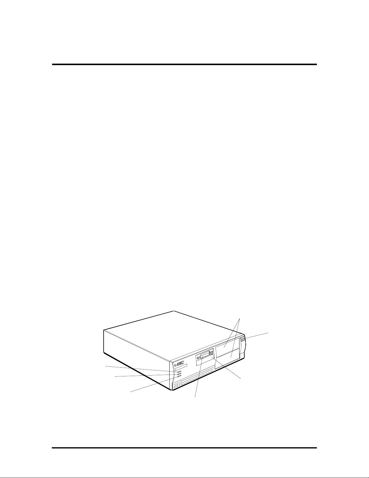
DESKTOP SYSTEM UNIT
The desktop chassis provides an enclosure for the system board, power supply, four storage
device slots, and a five-expansion-slot ISA/VESA Local Bus (VL-Bus™) backboard. The
storage device slots accommodate a 3 1/2-inch diskette drive, a 3 1/2-inch hard disk (1-inch
height), and two 5 1/4-inch storage devices (1.6-inch height). The system ships with a
3 1/2-inch diskette drive and a hard disk drive leaving two 5 1/4-inch storage device slots
available for optional devices. All desktop models share the system unit features shown in
Figure Section 1-1.
5 1/4-Inch Accessible
Slots (available)
Power Button
Power Lamp
Hard Disk Drive
Busy Lamp
Reset Button
3 1/2-Inch Accessible
Slot (contains 1.44-MB
diskette drive)
Figure Section 1-1 PowerMate Desktop System Unit Features
3 1/2-Inch Internal
Hard Disk Drive Slot
Page 15
1-2 Technical Information
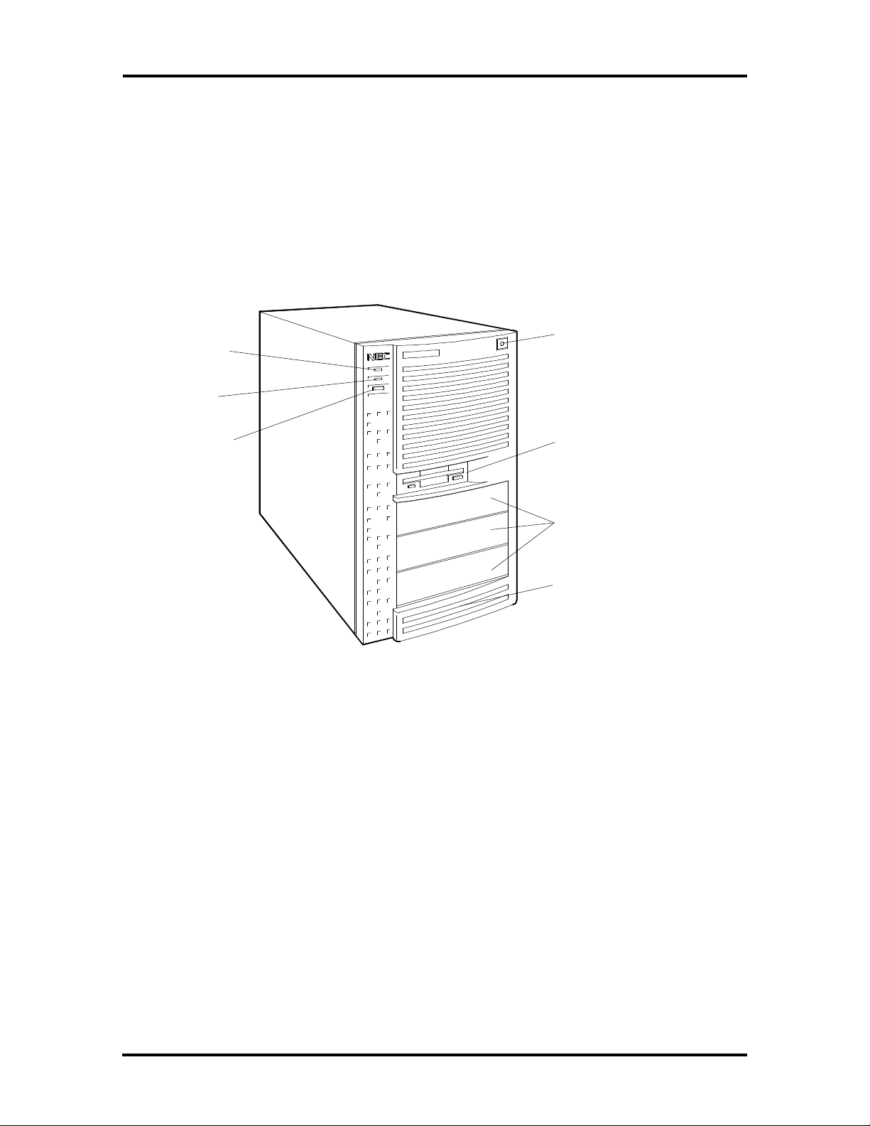
MINITOWER SYSTEM UNIT
The minitower chassis provides an enclosure for the system board, power supply, five storage device slots, and five-expansion-slot ISA/VL-Bus backboard. The storage device slots
accommodate a 3 1/2-inch diskette drive, a 3 1/2-inch hard disk (1-inch height), and three
5 1/4-inch storage devices (1.6-inch height). The system ships with a 3 1/2-inch diskette and
a hard disk drive leaving three 5 1/4-inch storage device slots available for optional devices.
All minitower models share the system unit features shown in Figure Section 1-2.
Power Lamp
Hard Disk
Drive Busy
Lamp
Reset Button
Power Button
3 1/2-Inch Accessible
slot (contains 1.44-MB
diskette drive)
5 1/4-Inch Accessible
slots
3 1/2-Inch Internal Slot
(contains hard disk)
Figure Section 1-2 PowerMate Minitower System Unit Features
Page 16

Technical Information 1-3
System Board
The system boards are similar, differing only in the processor. The system board contains a
Flash ROM which is upgradeable through the BIOS Update utility (see Section 2).
Key features of the system board are listed below.
n processor
Intel486SX™-33 – PowerMate 433D™
Intel486DX2™-66 – PowerMate 466D™
Intel486DX2-66 – PowerMate 466M™
Intel486DX4™-100 – PowerMate 4100M™
n support for Intel OverDrive™ processor upgrades
n 4 megabytes (MB) of random access memory (RAM) in the SX an DX2 systems
and 8 MB in the DX4 systems
accepts 36-bit (32-bit U.S. and Canada), 70-nano second (ns) single-inline
memory modules (SIMMs)
expandable to 128 MB
n 8-kilobyte (KB) primary cache (16 KB in the Intel486DX4)
n optional 256-KB secondary cache module
n Wingine video graphics array (VGA) controller and 32-bit Local Bus
supports 640 x 480 with 16.8 million colors (24-bit true color), 800 x 600
with 64 K colors 1024 x 768 resolution with 256 colors, and 1280 x 1024
resolution with 16 colors
1-MB (two 256K x 16) video dynamic RAM (DRAM), expandable to 2 MB
128-KB (256K x 4) standard video cache, expandable 256-KB
n two intelligent drive electronics (IDE) interface connectors
one fast local bus IDE connector (primary interface) used by the hard disk
drive to transfer data at the hard disk's optimum rate
one standard IDE connector (secondary interface) for additional IDE devices
(not used)
Page 17

1-4 Technical Information
n energy saving features: system switches to power save mode when idle for an es-
tablished amount of time
n 3 1/2-inch, 1.44-MB diskette drive
n ISA/VL-Bus backboard providing four ISA and one ISA/VL-Bus expansion slots
n external connectors providing an interface for the following external devices:
VGA-compatible monitor
personal system/2 (PS/2®)-style mouse
PS/2-style keyboard
enhanced capabilities port (ECP) for the parallel printer
two buffered serial ports
Table Section 1-1 lists the major chips on the system board. See Section 2, Setup and Operation, for a description of the system board's jumpers. See Appendix A, Connector Pin
Assignments, for a list of the system board connectors.
Table Section 1-1 System Board Chips
Chip Description
486SX – PowerMate 433D
486DX2 – PowerMate 466D and
PowerMate 466M
486DX4 – PowerMate 4100M
28F010 128k x 8 Flash ROM
VL82C483 System/cache/ISA Controller
VL82C003 Interrupt, I/O controller
VL82C114A Combination , I/O controller
VL82C611 VL-Bus controller
64300 Wingine
33-MHz processor
33/66-MHz processor
33/100-MHz processor
VGA controller
Page 18

Technical Information 1-5
Processor
The PowerMate systems use the following processors.
n PowerMate 433D – uses the 486SX with a 33 MHz clock speed
n PowerMate 466D and 466M – use the 486DX2 with a 66-MHz internal clock
speed and a 33-MHz external clock speed.
n PowerMate 4100M – use the 486DX4 with a 100-MHz internal clock speed and a
33-MHz external clock speed.
The processors are advanced 32-bit processors designed to optimize multitasking operating
systems. The 32-bit registers and data paths support 32-bit addresses and data types.
The processor is installed in a 237-pin, zero-insertion-force (ZIF) processor socket. This
socket allows the installation of the 486SX, DX2 and DX4 processors and the next generation of Intel OverDrive processors based on the Pentium core (PGA type package). When
upgrading processors they must operate with and external clock of 25 or 33 MHz.
The 486DX2 is exactly like previous 486DXs except that it runs twice as fast internally.
When the interface bus portion of the DX2 accesses main memory, executes I/O instructions, or accesses one of the other chips on the system board, the DX2 operates at 33 MHz.
The DX2 works at 66 MHz when accessing its internal registers, refers to a memory location alPowerMate mapped into its internal cache, or performs a floating-point operation and
CPU operations.
The DX4 runs three times as fast internally. When the interface portion accesses external
registers it operates at 33 MHz and works at 100 MHz when accessing its internal registers.
Secondary Cache
The 8-KB primary cache (16-KB of primary cache in the DX4) is integrated into the processor. The system board provides an 80-pin SIMM socket for an optional 256 KB of secondary cache, external to the processor. Cache memory improves read performance by
holding copies of code and data that are frequently requested from the system memory by
the processor. Cache memory is not considered part of the possible 128 MB of total memory capacity.
The cache is connected directly to the processor address bus and uses physical addresses. A
bus feature known as burst enables fast cache fills. Memory areas (pages) can be designated
as cacheable or non-cacheable by software. The cache can also be enabled and disabled by
software.
The write strategy of the cache (primary and secondary) is write-through. If the write is a
cache hit, an external bus cycle is generated and information is written to the cache. Any
area of memory can be cached in the system. Non-cacheable portions of memory are defined by software. The cache can be cleared by software instructions.
Page 19

1-6 Technical Information
Flash ROM
Machine language programs are stored in a 28F010 Flash ROM known as the system's
ROM BIOS. The system BIOS and video BIOS are contained in the ROM. The Flash ROM
is 128 KB, which consists of 64 KB of system BIOS, and 32 KB of video BIOS.
The Flash ROM allows the BIOS to be upgraded with the BIOS Update utility without removing the ROM (see Section 2, Setup and Configuration). The BIOS can only be reprogrammed by powering on the system with the BIOS Update utility diskette in Drive A.
The BIOS programs execute the Power-On Self-Test, initialize processor controllers, and
interact with the display, diskette drives, hard disks, communication devices, and peripherals. The system BIOS also contains the Setup program and provides VGA controller support. The hardware setup default copies the ROM BIOS into RAM (shadowing) for
maximum performance.
System BIOS is located in the upper portion of the Flash ROM and video BIOS in the
lower portion. System BIOS is located between F0000h-FFFFFh and supports shadowing
and shadowed memory. System BIOS is write protected and automatically enabled.
Video BIOS is located between C0000h and C7FFFh. If the internal video is disabled, this
range is mapped to ISA. The system memory map in shown in Table Section 1-2.
Table Section 1-2 System Memory Map
Memory Space Size Function
000000-07FFFF 512 KB Reserved for system base memory
080000-09FFFF 128 KB Mapped to either system base memory or ISA bus*
0A0000-0BFFFF 128 KB Mapped to either on-board video memory or ISA video memory
0C0000-0C7FFF 32 KB Mapped to either on-board video BIOS or ISA video BIOS
0C8000-0EFFFF 160 KB Mapped to ISA bus
0F0000-0FFFFF 64 KB Reserved for system BIOS
100000-FDFFFF 14.9 MB Reserved for Extended and/or Expanded system memory
FE0000-FFFFFF 128 KB Mapped to ISA bus
1000000- On-Board 14.9 MB Reserved for Extended and/or Expanded system memory
*Always non-cachable.
Page 20

Technical Information 1-7
Flash ROM supports the reprogramming of the system and built-in video BIOS. Software
controls this feature via port 94h. Flash ROM programming writes to location 0F0000h0FFFFFh. This range allows access to 64 KB of the 128 KB ROM. To write to the rest of
the ROM, bit 3 of port 94h must be set. Again, writing to 0F0000h-0FFFFFh allows the
rest of the ROM to be programmed. (Setting bit 3 on port 94h maps the 0F0000h to
0E0000h range.)
Power Management
Each computer system incorporates power management features that lowers power consumption when there is no activity detected from the keyboard, mouse, diskette drive, CDROM reader, or hard disk drive after a pre-defined period of time. As soon as activity is
detected the system resumes where it left off.
When Power Management is enabled the computer automatically activates power-saving
features and enters a sleep mode whenever inactivity is sensed. The computer's powersaving functions are as follows.
n Reduces the CPU clock speed
The CPU clock speed is changed from 33 MHz to 8 MHz (16 MHz in the
PowerMate 4100M) to put the computer in sleep mode. The cache and video
clocks are changed at the same time.
n Blanks out the monitor
Puts the video controller into sleep mode. The vertical sync clock and blank signals to the monitor are disabled.
n Forces the IDE devices into stand-by mode
A suspend command is sent to the IDE devices which put the devices into a
stand-by mode.
Page 21

1-8 Technical Information
I/O Addressing
The processor communicates with I/O devices by I/O mapping. The hexadecimal (hex) addresses of I/O devices are listed in Table Section 1-3.
Table Section 1-3 I/O Address Map
Address (Hex) I/O Device Name
000-01F DMA controller 1 (channel 0-3)
020-03F Interrupt controller
040-05F Timer
060-063 PPI (Programmable Peripheral Interface) keyboard, equipment switches,
timer
060-06F Keyboard controller
070-07F Real-time clock, CMOS memory, NMI mask
080 Manufacturer's diagnostic checkpoint
081-09F DMA page register
0A0-0AF NMI (non-maskable interrupt) mask
092 PS/2 alternate Fast A20 Gate, Hot Reset
094 Extended system port (NEC-specific hardware setup)
095 Extended system port (NEC-specific hardware setup)
097 Extended system port (NEC-specific hardware setup)
0A0-0BF Interrupt controller 2
0C0-0DF DMA controller 2 (channel 4-7)
0E0-0EF Reserved
170-177 2nd hard disk
1F0-1F7 1st hard disk
1F9-1FF Reserved
200-207 Game I/O adapter (not available)
278-27F 2nd parallel port (3rd with DMA)
2F8-2FF 2nd asynchronous communications port
370-377 Diskette controller 2
378-37F 1st parallel port (2nd with DMA)
3A0-3AF Primary bisynchronous communications port
3B0-3DF Video Graphics Array (VGA)
3B0-3BF Monochrome display adapter/printer 1
3C0-3CF Enhanced Graphics Adapter (EGA) 1
Page 22

Technical Information 1-9
Table Section 1-3 I/O Address Map
Address (Hex) I/O Device Name
3D0-3DF Color/Graphics Adapter (CGA and EGA)
3F0-3F7 Diskette Controller
3F8-3FF Asynchronous Adapter Port 1
System Memory
The PowerMate 433D, 466D, and 466M system boards come standard with 4 MB of RAM.
The PowerMate 4100M system board comes standard with 8 MB of RAM. The first megabyte includes the standard 640 KB of base memory. The remaining memory is extended
memory. Four SIMM sockets are integrated on the system board. In the 433D, 466D, and
466M, one socket contains a 4-MB SIMM and three sockets are empty for installing up to
three additional SIMMs. The 4100M contains two 4-MB SIMMs and two sockets are
empty for installing additional SIMMs. The maximum possible memory is 128 MB.
The SIMM memory sockets accept 4-, 8-, 16-, or 32-MB SIMMs. When the standard
4-MB SIMM is removed (8-MB in the 4100M), four 32-MB SIMMs may be installed for a
total of 128 MB. High-speed RAM is 32 bits wide (no parity bits). SIMMs are 1 MB x 32
bit (4 MB), 4 MB x 32 bit (16 MB), and 8 MB x 32 bit (32 MB). There are no switches or
jumpers to set when SIMMs are added.
CAUTION: SIMMs must match the tin metal
plating used on the system board SIMM sockets.
When adding SIMMs, use tin-plated SIMMs.
SIMMs install directly on the system board. Different size SIMMs may be intermixed. Each
SIMM is inserted into a socket or bank. The standard 4 MB of memory is installed in bank
0 in the PowerMate 433D, 466D, and 466M. The PowerMate 4100M has two 4 MB
SIMMs installed in banks 0 and 1. The system board's four SIMM sockets are assigned as
banks 0 through 3. See Section 3, Options, for installation instructions and SIMM memory
configurations.
Interrupt Controller
The interrupt controller operates as an interrupt manager for the entire AT system environment. The controller accepts requests from peripherals, issues interrupt requests to the
processor, resolves interrupt priorities, and provides vectors for the processor to determine
which interrupt routine to execute. The interrupt controller has priority assignment modes
that can be reconfigured at any time during system operations.
Page 23

1-10 Technical Information
The interrupt levels are described in Table Section 1-4. Interrupt-level assignments 0
through 15 are in order of decreasing priority. See Section 2, Setup and Configuration, for
information on changing the interrupts using Setup and jumpers.
Table Section 1-4 Interrupt Level Assignments
Interrupt Priority Interrupt Device
IRQ00 Counter/Timer
IRQ01 Keyboard
IRQ02 Cascade (INT output from slave)
IRQ03 COM2*
IRQ04 COM1*
IRQ05 Available
IRQ06 Diskette Drive Controller*
IRQ07 Parallel Port 1*
IRQ08 Real-time clock
IRQ09 Available
IRQ10 Available
IRQ11 Available
IRQ12 PS/2 mouse*
IRQ13 Coprocessor
IRQ14 Primary IDE (fast)
IRQ15 Secondary IDE (standard)
*Industry standard locations
Video Controller
The 64300 Wingine DGX video controller with Local Bus video combines powerful elements aimed at addressing the requirements of personal computer designs. State of the art
techniques have been added for optimizing performance in computer graphic intensive applications and graphical user interfaces (GUI). A variety of industry standard 32-bit local
bus interfaces are integrated on chip, including VESA Local Bus (VL-Bus). The key is that
local bus interfaces are 32-bit wide.
Included in the video controller are cost saving features such as an integrated palette DAC
and clock synthesizer along with integrated support for multiple bus interfaces and flexible
DRAM-based display memory configurations.
Page 24

Technical Information 1-11
The 64300 video controller supports XRAM Accelerator Cache, power management, flash
ROM, and a linearly mapped display.
The XRAM Accelerator Cache is a breakthrough in performance technology. By using one
standard 256K x 4 fast page DRAM, a proprietary algorithm implemented in the 64300 significantly increases graphics system performance. Performance never before achieved in
standard dram-based graphics architectures.
When using the 64300 Wingine DGX, a system host CPU’s performance is enhanced and a
significant improvement will be observed in the display. Other DRAM-based graphics accelerators gain some degree of performance which, while measurable, is not as significant nor
as noticeable on the display.
The TrueColor RAMDAC provides 24-bit true color. The integrated dual clock synthesizer
allows full programmability of MCLK (memory clock) and PCLK (pixel clock). The integrated clock synthesizer supports frequencies from 390 kHz to 120 MHz. The 64300 supports up to 2 MB of display memory. The video memory is 256K x 16 Fast Page Mode
DRAM. Display memory is linearly mapped up to 2 MB.
The VESA display power management signaling (DPMS) standard is supported, enabling
stand-by, suspend, and off power saving modes. This includes the ability to independently
stop HSYNC of VSYNC and hold them at a static level. Additionally the RAMDAC may
be powered-down and the clock frequencies lowered for further power savings. Color Key
and video overlay are supported.
Page 25

1-12 Technical Information
Video Memory
The 1 MB of on-board video DRAM is expandable to 2 MB and provides graphic resolutions of or 640 x 480 with 16.8 million colors, 800 x 600 with 64K colors, 1024 x 768 with
256 colors, or 1280 x 1024 with 16 colors. Table Section 1-5 and Table Section 1-6 provide the different display modes for the video controller.
Table Section 1-5 Text Modes
Mode
(Hex)
1
00
2
00
3
00
1
01
2
01
3
01
1
02
2
02
3
02
1
03
2
03
3
03
4
07
3
07
5
60
5
24
Colors
Column/
Rows
Buffer
Resolution
Video
Clock
(MHz)
Horiz
Sync
(kHz)
Vert Sync
(Hz)
16 (grey) 40 x 25 B8000 320 x 200 28.2 31.7 70
16 (grey) 40 x 25 B8000 320 x 350 28.3 31.7 70
16 40 x 25 B8000 360 x 400 28.2 31.7 70
16 40 x 25 B8000 320 x 200 28.2 31.7 70
16 40 x 25 B8000 320 x 350 28.2 31.7 70
16 40 x 25 B8000 360 x 400 28.2 31.7 70
16(grey) 80 x 25 B8000 640 x 200 28.2 31.7 70
16(grey) 80 x 25 B8000 640 x 350 28.2 31.7 70
16 80 x 25 B8000 720 x 400 28.2 31.7 70
16 80 x 25 B8000 640 x 200 28.2 31.7 70
16 80 x 25 B8000 640 x 350 28.2 31.7 70
16 80 x 25 B8000 720 x 400 28.2 31.7 70
mono 80 x 25 B8000 720 x 350 28.2 31.5 70
mono 80 x 25 B8000 720 x 400 28.2 31.5 70
16 132 x 25 B8000 1056 x 400 40.0 30.5 67.5
16 132 x 30 B8000 1056 x 400 40.0 30.5 67.5
1CGA-style text mode with 8x8 character size and 200 lines vertical resolution.
2
EGA-style text mode with 8x14 and 9x14 character sizes and 350 lines vertical resolution.
3
VGA-compatible text mode with 9x16 character size and 400 lines vertical resolution.
4
MDA- style text mode with 9x14 character sizes and 350 lines vertical resolution.
5
Enhanced VGA mode.
Page 26

Technical Information 1-13
Table Section 1-6 Graphic Modes
Mode
(Hex)
1
04
1
05
1
06
1
0D
1
0E
2
0F
2
10
2
11
2
12
2
13
2
20
2
22
2,3
24
2
30
2
32
2,3
34
2,3
38
2
40
2
41
2,
42
2,
43
2,3
44
2,3
45
2
50
2
6A
2
70
2,3
75
3
76
2
78
2
79
Colors
Column
/Rows
Buffer
Resolution
Video
Clock
(MHz)
Horiz
Sync
(kHz)
Vert
Sync
(Hz)
4 40 x 25 B8000 320 x 200 25.2 31.5 70
4 40 x 25 B8000 320 x 200 25.2 31.5 70
2 80 x 25 B8000 640 x 200 25.2 31.5 70
16 40 x 25 A0000 320 x 200 25.2 31.5 70
16 80 x 25 A0000 640 x 200 25.2 31.5 70
mono 80 x 25 A0000 640 x 350 25.2 31.5 70
16 80 x 25 A0000 640 x 350 25.2 31.5 70
2 80 x 30 A0000 640 x 480 25.2 31.5 70
16 80 x 30 A0000 640 x 480 25.2 31.5 60
256 40 x 25 A0000 320 x 200 25.2 31.5 70
16 80 x 30 B8000 640 x 480 40.0 30.5 60
16 100 x 37 A0000 800 x 600 25.2 31.5 60
16 128 x 48 A0000 1024 x 768 32.6 31.5 73
256 80 x 30 A0000 640 x 480 36.0 35.5 56
256 100 x 37 A0000 800 x 600 40.0 38.0 60
256 128 x 48 A0000 1024 x 768 50.4 48.4 73
256 80 x 25 A0000 1280 x 1024 25.2 31.5 70
32k 80 x 30 A0000 640 x 480 25.2 31.5 60
64k 80 x 30 A0000 640 x 480 32.6 31.5 73
32k 100 x 37 A0000 800 x 600 25.2 31.5 70
64k 100 x 37 A0000 800 x 600 36.0 35.5 56
32k 128 x 48 A0000 1024 x 768 40.0 38.0 60
64k 128 x 48 A0000 1024 x 768 50.4 48.4 73
16M 80 x 30 A0000 640 x 480 44.9 35.5 87
16 100 x 37 A0000 800 x 600 65.0 49.0 61
16 100 x 37 A0000 800 x 600 72.0 56.6 70
16 128 x 48 A0000 1024 x 768 44.9 35.5 87
16 160 x 64 A0000 1280 x 1024 72.0 56.6 70
256 80 x 25 A0000 640 x 400 72.0 56.6 70
256 80 x 30 A0000 640 x480 44.9 35.5 87
Page 27

1-14 Technical Information
Table Section 1-6 Graphic Modes
Mode
(Hex)
2
7C
2,3
7E
18x8 charactor size
2
8x16 charactor size
3
Interlaced
Colors
256 100 x 37 A0000 800 x 600 72.0 56.6 70
256 128 x 48 A0000 1024 x 768 80.0 48.1 87
Column
/Rows
Buffer
Resolution
Video
Clock
(MHz)
Horiz
Sync
(kHz)
Vert
Sync
(Hz)
ISA/VL-Bus Backboard
The ISA/VL-Bus backboard provides four ISA expansion slots and one Video Electronics
Standards Association (VESA) Local Bus (VL-Bus) slots. The backboard is plugged into
two bus connectors on the system board.
ISA Bus
The system board uses the ISA bus for transferring data between the processor and I/O peripherals and expansion boards. The ISA bus supports 8- and 16-bit data transfers and typically operates at 8.33 MHz. A connector is provided on the system board for attaching the
ISA/VL-Bus backboard.
VL-Bus
The VL-Bus provides an interface between the system's local bus and a VL-Bus option
board (graphics adapters, disk controllers, network cards, and so on). The VL-Bus uses a
standard 32-bit VESA connector and conforms with the VESA 1.1 local bus specification,
providing a set of standards that ensure compatible VL-Bus option boards. The boards operate at the system clock speed (33 MHz) with 0 wait states. The VL-Bus slot can support
bus masters simultaneously.
Option boards on the VL-Bus can send and receive data much faster on the local bus than
on the ISA bus. The VL-Bus runs at the system's clock speed (33 MHz) instead of the standard ISA bus speed (8 MHz). Also, the Local Bus provides a wider bus width (32 bits) than
the standard ISA bus width (16 bits).
The VL-Bus slot is used in conjunction with an ISA bus slot. This feature allows a VL-Bus
option board full access to the ISA bus. For example, the VL-Bus option board may utilize
the parallel port via the ISA bus, or use the ISA bus REFRESH signal. Use of the ISA bus
is optional, as the VL-Bus has all signals needed to fully support a VL-Bus option board.
Page 28

Technical Information 1-15
Parallel Interface
The system has a 25-pin parallel port on the system board. Specifications for this port conform to the IBM-PC standards.
The BIOS has automatic ISA printer port sensing. If the BIOS detects an ISA printer port
mapped to the same address, the built-in printer port is disabled. The BIOS also sets the
first parallel interface port it finds as LPT1 and the second port it finds as LPT2. The interrupt is selected to either IRQ5 or IRQ7 via the Setup and jumper settings.
Interrupt levels for the parallel port are given in Table Section 1-7. Software selectable base
addresses are 3BCh, 378h, and 278h.
Parallel interface signals are output through the system board's 25-pin, D-subconnector. The
connector is located at the rear of the system unit. Pin locations for the parallel interface
connector are shown in Appendix A.
NOTE: Any interrupts used for the built-in par-
allel port is not available for ISA parallel ports.
Table Section 1-7 Parallel Port Addressing and Interrupts
Starting I/O Address Interrupt Level Port
378 IRQ05 LPT1
278 IRQ05 LPT1 or LPT2
3BC IRQ05 LPT1 or LPT2
378* IRQ07 LPT1
278 IRQ07 LPT1 or LPT2
3BC IRQ07 LPT1 or LPT2
*Default for parallel port
Page 29

1-16 Technical Information
Serial Interface
The system has two standard serial ports (COM1 and COM2). The serial ports support the
standard RS-232C interface (16550 compatible). I/O addresses and interrupt levels for the
two channels are given in Table Section 1-8. The interrupt is selectable via Setup to either
IRQ3 or IRQ4. Software selectable base addresses are 3F8h, 2F8h, 3E8h, and 2E8h. Serial
interface signals are output through the system board's 9-pin, D-subconnector. The connectors are located at the rear of the system unit. Pin locations for the serial interface connector are shown in Appendix A
NOTE: Any interrupts used for the built-in serial
ports are not available for ISA parallel ports.
Table Section 1-8 Serial Port Addressing and Interrupts
Starting I/O Address Interrupt Level Port
3F8 IRQ04 COM1
2F8* IRQ03 COM2
3E8 IRQ04 COM3
2E8 IRQ03 COM4
*Default for serial port
Serial interface specifications include:
n Baud rate up to 19.2 KB per second
n Word length - 5, 6, 7, or 8 bits
n Stop bit - 1, 1.5, or 2 bits
n Start bit - 1 bit
n Parity bit - 1 bit (odd parity or even parity).
Indicator Panel
The indicator panel is attached to the front panel and contains the power lamp, hard disk
drive busy lamp, and reset button. The indicator panel attaches to the system board using
connector P5 (reset connector), P7 (hard disk drive busy lamp connector), and P15 (power
lamp connector).
Page 30

Technical Information 1-17
POWER SUPPLY
The power supply is mounted inside the system unit. It supplies power to the system board,
option boards, diskette drives, hard disks, keyboard, and mouse. Two connectors connect
the power supply to the system board. A fan inside the power supply provides proper ventilation for the system. The power supply in the desktop supplies 145W of power. The
minitower power supply provides 200W. Power requirements and specifications for both
power supplies are provided in Appendix C.
DISKETTE DRIVE
Up to two diskette drives are supported in the system. The drives are connected by a single
ribbon cable with two drive connectors. The system refers to the diskette drives as A and B.
Drive A is for the first drive, B is for a second optional diskette drive. The diskette drive
cable plugs directly into the system board. Typically both diskette drive are terminated. See
Section 3, Options, for installing an optional 5 1/4-inch diskette drive.
Specifications for the diskette drives are provided in Appendix B, Specifications.
HARD DISK DRIVE
The system provides IDE interface connectors on the system board. The system board supports up to two IDE devices on the standard connector and two IDE devices on the fast local bus IDE connector. The system unit provides one storage slot for a 3 1/2-inch hard disk
(1-inch height), and one available storage slots for a optional 5 1/4-inch device (1.6-inch
height). See Section 3, Options, for installing an optional hard disk drive.
Specifications for the diskette drives are provided in Appendix B, Specifications.
KEYBOARD
The PS/2-style keyboard is standard equipment for the system. The keyboard provides a
numeric keypad, separate cursor control keys, and 12 function keys, capable of up to 48
functions. Status lamps on the keyboard indicate: Num (Numeric) Lock, Caps (Capital)
Lock, and Scroll Lock key status. The keyboard's six-pin connector is plugged into the rear
of the base unit. The PS/2-style keyboard connector pin assignments are given in Appendix A, Connector Pin Assignments.
Page 31

Section 2
Setup and Operation
This section provides information on hardware setup for PowerMate Series computers.
Setup includes unpacking, cabling, and powering up the system. It also includes configuring
the system with the system setup programs. Section 3 provides information for installing
options.
UNPACKING AND REPACKING
Find an area away from devices that generate magnetic fields (electric motors, transformers,
etc.). Place the carton on a sturdy surface, and carefully unpack the system. The carton
contents include the system unit, keyboard, mouse, power cord, user documentation, and
system recovery diskette.
Repack the system using the original shipping carton and packing material. Part numbers for
replacement shipping cartons and packing material are available at the end of Sections 5
and 6.
SETUP
Connect the system components according to the following two subsections.
n Desktop Configuration – for setting up desktop system units.
n Minitower Configuration – for setting up minitower system units.
Page 32

2-2 Setup and Operation
Desktop Setup
Set up the desktop systems by making the following connections. (See the following subsection, Minitower Setup, if setting up a minitower computer).
1. At the rear of the system, set the voltage selector switch to 115V or 230V and in-
sert the power cord into the system power socket (see Figure 2-1).
CAUTION: The correct AC input voltage must
be properly set. Select the appropriate voltage
with the voltage selector switch located at the
rear of the system.
Voltage Selector
Switch
System Power
Socket
Figure Section 2-1 Desktop Voltage Selector Switch
Page 33

Setup and Operation 2-3
2. Connect the keyboard and mouse cables to the back of the system unit (see
Figure 2-2).
3. Connect the, monitor and any other peripherals to the rear panel (see Figure 2-2).
Detailed monitor connections a given in Sections 3, Options.
15-Pin VGA
Monitor
Connector
Parallel
Printer Port
Serial
Port 2
Serial
Port 1
Mouse
Port
Keyboard
Port
Figure Section 2-2 Desktop Peripheral Connections
4. Press the power button to power-on the system (see Figure 2-4). The user lamps
and reset button are also identified in the figure.
Power
Button
Power
Lamp
Hard Disk Drive
Busy Lamp
Reset
Button
Figure Section 2-3 Desktop Lamps, Reset Button, and Power Button
Page 34

2-4 Setup and Operation
The system has a built-in checking program that automatically tests the components at
power-on. One beep indicates that the system has successfully completed its power-on test.
If there is a problem, a series of beeps may occur. If this happens repeatedly after powering
on the system, power off the system and see Section 4 for troubleshooting.
NOTE: If the system displays a message
indicating that system settings have changed, run
Setup (see “System Configuration” later in this
section).
If a problem occurs, and is not indicated by beeps, check the following items, then turn to
Section 4 for troubleshooting. Check that:
n the power switch for the system unit and monitor are on.
n all cables and power cords are tightly connected.
n the electrical outlet is working.
n the monitor's brightness and contrast are adjusted properly.
n all options are properly installed (see Section 3 for option installation).
Page 35

Setup and Operation 2-5
Switch
Minitower Setup
Set up the minitower systems by making the following connections. (See the preceding subsection, Desktop Setup, if setting up a desktop computer).
1. At the rear of the system, set the voltage selector switch to 115V or 230V and in-
sert the power cord into the power socket (see Figure 2-5).
CAUTION: The correct AC input voltage must
be properly set. Select the appropriate voltage
with the voltage selector switch located at the
rear of the system.
System Power
Socket
Voltage Selector
Figure Section 2-4 Minitower Voltage Selector Switch
Page 36

2-6 Setup and Operation
2. Connect the keyboard and mouse cables to the back of the system unit (see
Figure 2-6).
3. Connect the monitor and any other peripherals to the rear panel (see Figure 2-6).
Detailed monitor connections a given in Sections 3, Options.
Expansion
Slot Covers
15-Pin VGA
Monitor Connector
Parallel
Printer Port
Serial Port 2
Serial Port 1
Keyboard Port
Mouse Port
Figure Section 2-5 Minitower Peripheral Connections
4. Press the power button to power-on the system (see Figure 2-8). The user lamps
and reset button are also identified in the figure.
Hard Disk Drive
Busy Lamp
Power
Lamp
Power
Button
Reset
Button
Figure Section 2-6 Minitower Indicators, Reset Button, and Power Button
Page 37

Setup and Operation 2-7
The system has a built-in checking program that automatically tests the components at
power-on. One beep indicates that the system has successfully completed its power-on test.
If there is a problem, a series of beeps may occur. If this happens repeatedly after powering
on the system, power off the system and see Section 4 for troubleshooting.
NOTE: If the system displays a message
indicating that system settings have changed, run
Setup (see “System Configuration” later in this
section).
If a problem occurs, and is not indicated by beeps, check the following items, then turn to
Section 4 for troubleshooting. Check that:
n the power switch for the system unit and monitor are on.
n all cables and power cords are tightly connected.
n the electrical outlet is working.
n the monitor's brightness and contrast are adjusted properly.
n all options are properly installed (see Section 3 for option installation).
Page 38

2-8 Setup and Operation
SYSTEM CONFIGURATION
This subsection describes the Setup utility program that allows the system configuration
information to be viewed and changed.
NOTE: The system ships from the factory with
the correct system parameters for the configuration. Unless adding optional hardware, Setup
does not need to be run.
However, run Setup to set features that customize the system, such as security features.
System configuration information is stored in nonvolatile memory. Nonvolatile memory in
the system is a complementary metal-oxide semiconductor (CMOS) chip backed up by a
battery on the system board. The battery supplies continuous power to the CMOS memory
and maintains configuration information when system power is off.
Setup Utility
The Setup utility is used to view and set system parameters. Use the Setup utility program:
n to set the time and date.
n to update or check system parameters when adding or removing expansion op-
tions.
n to correct a hardware discrepancy when the Power-On-Self-Test (POST) displays
an error message and a prompts appears to run Setup.
n to check the installation of optional memory by comparing the amount memory
installed with the amount of memory displayed by Setup.
n to change certain system operating parameters.
n to customize the system with security features such as passwords and I/O control
functions.
n to set system parameters in the event that the system battery needs to be replaced.
Page 39

How to Start Setup
To start the Setup utility, follow these steps:
1. Turn on or reboot the system. Setup displays the following message:
Press <F2> to enter SETUP
2. Press F2. Setup’s Main Menu window appears similar to the following screen.
NOTE: The screen shown is typical of the sys-
tem. The actual items on the Main Menu depend
upon the hardware installed in the system.
Setup and Operation 2-9
How to Use Setup
The Setup utility has a Main Menu window and five top-level menus with submenus.
The Main Menu window contains the following areas:
n A title line — the top line of the Main Menu. This line displays the Setup utility
name and copyright message.
n The menu bar — the line under the Setup title line. The menu bar contains five
top-level menus for setting system parameters.
n A Main Menu summary window — the center area on the left side of the screen.
This area provides a summary of Main Menu Setup parameters. Main Menu
parameters can be set directly from this window or from the Main menu option in
the legend bar.
n The Field Help window or Item Specific Help — the area on the right side of the
screen. This help area provides help information for the Setup option currently
selected.
Page 40

2-10 Setup and Operation
n The legend bar — the area at the bottom of the screen. The legend bar provides a
summary of command keys for using Setup.
n The General Help window — a window that appears any time during Setup after
pressing F2 or Alt H . This help window provides two pages of general information about using Setup.
The following sections describe how to use the Main Menu window to set system
parameters.
Menu Bar
The menu bar at the top of the Main Menu window lists these menus:
n Main — Use this menu for basic system configuration. For example, select
“Main” to set the system time, system date, diskette drives, and video parameters.
Use this menu to check memory parameters.
n Advanced — Use this menu to set serial port and printer port addresses and inter-
rupts, to enable/disable the system’s diskette drive controller and dual-IDE controllers.
The Advanced menu also provides menu items for setting parity and for setting
parameters for large disks (for example, to use large disks with Windows NT).
Some of the Advanced features are accessible only with a Supervisor password.
n Security — Use this menu to set User and Supervisor Passwords and the Backup
and Virus-check reminders.
n Power — Use this menu to configure Power-Management features.
n Exit — Exits the current menu.
To select an option from the menu bar, use the left and right ←← →→ arrow keys.
See “Exiting Setup” in this chapter for a description on exiting the Main Menu.
Page 41

Setup and Operation 2-11
Legend Bar
Use the keys listed in the legend bar on the bottom of the Setup menu to make the selections or exit the current menu. The following table describes the legend keys and their alternates.
Table Section 2-1 Setup Key Functions
Key Function
F1 or Alt-H Displays General Help window (described later in this chapter).
Esc Exits the menu.
← or → arrow keys
↑ or ↓ arrow keys
Tab or Shift-Tab Cycles cursor up and down.
Home or End Moves cursor to top or bottom of window.
Page Up or Page Down Moves cursor to next or previous page.
F5 or - Selects the Previous Value for the field.
F6 or + or Space Selects the Next Value for the field.
F9 Loads the Default Configuration values for this menu.
F10 Loads the Previous Configuration values for this menu.
Enter
Alt-R Refreshes screen
n Selecting a Menu Item
Selects a different menu.
Moves cursor up and down.
Executes Command or Selects submenu.
To select a menu item, use the arrow keys to move the cursor to the desired field.
Then use the value keys (F5, –, F6, +, or space bar) to cycle through the value for
that field. The Save Values command in the Exit Menu saves the values currently
displayed in all the menus.
n Displaying a Submenu
To display a submenu, use the arrow keys to move the cursor to the desired submenu. Then press Enter. A pointer (a right-pointing triangle) marks all selectable
submenus.
Field Help Window
The Field Help window or Item Specific Help window on the right side of each menu displays the help text for the currently selected Setup option. It updates as the cursor is moved
to each new field.
Page 42

2-12 Setup and Operation
General Help Window
Pressing F1 or Alt H on any menu brings up the General Help window that describes the
legend keys and their alternates.
The scroll bar on the right of any window indicates that there is more than one page of information in the window. Use Page Up and Page Down to display all the pages. Pressing
Home and End displays the first and last page.
Press Esc to exit the current window.
Main Menu Options
Table Section 2-2 lists and describes the available parameters when the Main menu is selected in the legend bar. Other Main Menu parameters are available directly from Main
Menu summary window.
Parameters available directly from the Main Menu summary window have a right-pointing
triangle next to the parameter. Use the arrow keys to move the cursor to parameter and
press Enter to select a submenu.
See the sections following Table Section 2-2 for a description of Main Menu parameters
from the summary window.
Table Section 2-2 Legend Bar Main Menu Parameters
Parameter Options Description
System Time HH:MM:SS Sets the system time.
System Date MM/DD/YYYY Sets the system date.
Diskette A:
Diskette B:
Video System Monochrome
System Memory Automatically detected
Extended Memory Automatically detected
360KB, 5 1/4”
1.2MB, 5 1/4”
720KB, 3 1/2”
1.44MB, 3 1/2”
2.88MB, 3 1/2”
Not Installed
EGA/VGA, (default)
CGA 80x25
by the system
by the system
Selects the type of diskette drive in the system.
Selects the default video device.
Displays the amount of conventional memory
detected at power-on.
Displays the amount of extended memory
detected at power-on.
Page 43

Setup and Operation 2-13
IDE Adapters
IDE adapters control the IDE devices, such as IDE hard disk drives and IDE CD-ROM
readers, in the system. The system uses two IDE controllers integrated on the system board.
Setup supports up to four IDE devices, with an IDE adapter for each of the following configurations:
1 Master
1 Master, 1 Slave
2 Masters
2 Masters, 1 Slave
2 Masters, 2 Slaves
The master/slave combination for standard configurations with an IDE hard disk is “1
Master.” If adding a hard disk to the fast IDE port (primary channel), the combination becomes “1 Master, 1 Slave.” Jumper settings on the IDE device set the device to master or
slave (see the documentation that comes with the device).
Select the IDE Adapter option configuration directly from the Main Menu summary window. Available options include:
n IDE Adapter 0 Master
n IDE Adapter 0 Slave
n IDE Adapter 1 Master
n IDE Adapter 1 Slave
IDE Adapter 0 configures the fast IDE port (primary channel), IDE Adapter 1 configures
the standard IDE port (secondary channel).
Each IDE Adapter parameter has a right-pointing arrow to the left of it. Selecting the option displays IDE hard disk parameters. Select an IDE Adapter option and set parameters
for each hard disk separately.
Use the following table to configure the hard disk. If the IDE hard disk features auto IDE
type detection, select the Autotype Fixed Disk parameter. The system then automatically
detects the hard disk type and sets the remaining parameters.
Page 44

2-14 Setup and Operation
Table Section 2-4 IDE Hard Disk Parameters
Parameter Options Description
Autotype Fixed
Disk
Type 1 to 39 User Selecting 1 to 39 fills in all remaining fields with
Heads 1 to 64 Specifies number of read/write heads.
Sectors/Track 1 to 63 Specifies number of sectors per track.
Landing Zone* 1 to 2048 Specifies number of cylinder specified as the
Write Precomp* 1 to 2048
*IDE drives do not require setting Landing Zone and Write Precomp.
Automatically detected
by the system
None
Pressing Enter causes the system to attempt to
detect the hard disk type. If successful, Setup fills
in the remaining fields on this menu and disk
parameters need not be selected.
values for predefined disk type. “User” prompts
user to fill in remaining fields.
landing zone for the read/write heads.
Specifies number of the cylinder at which to
change the write timing.
Memory Shadow
For memory shadowing parameters, select “Memory Shadow” directly from the Main Menu
summary window. See the following table for a description of Memory Shadow parameters.
CAUTION: Incorrect settings can cause the
system to malfunction.
Table Section 2-5 Memory Shadow Parameters
Parameter Options Description
System shadow Not user-
selectable
Video shadow Not user-
selectable
Shadow Memory
Regions
Enabled
Disabled
Always enabled. Shadows video BIOS and
improves performance.
Always enabled. Shadows video BIOS and
improves performance.
Default is disabled. Shadows optional ROM
located in specified segments of memory and can
improve performance. CAUTION: Some add-in
cards, particularly with on-board firmware, do not
work properly when shadowed.
Page 45

Setup and Operation 2-15
Boot Sequence
The system might require a Supervisor password to set Boot Sequence parameters. Select
“Boot Sequence” directly from the Main Menu summary window to display the “Boot Options” menu.
Use the legend keys to make the selections and exit to the Main Menu. Use the following
table to select the boot options.
Table Section 2-6 Boot Parameters
Parameters Options Description
Boot sequence A: then C: (default)
C: then A:
C: only
Setup prompt Enabled (default)
Disabled
POST errors Enabled (default)
Disabled
Floppy check Enabled (default)
Disabled
Summary screen Enabled (default)
Disabled
Last Boot Fail 2 – 5
Disabled (default)
The BIOS attempts to load the operating system
from the disk drives in the sequence selected
here.
“C: only” (under Supervisor password control)
provides virus protection.
Displays “Press<F2> for Setup” during bootup.
At boot error, pauses and displays “Press <F1> to
resume, <F2> for Setup”.
Seeks diskette drives during bootup. Disabling
speeds boot time.
Describes system configuration at the end of
bootup.
Number of times the system an fail to boot before
the boot fail message appears.
Numlock
Select “Numlock” directly from the Main Menu summary window to display the Keyboard
Features menu.
Use the legend keys to make the selections and exit to the Main Menu. Use the following
table to configure the keyboard parameters.
Page 46

2-16 Setup and Operation
Table Section 2-7 Numlock Parameters
Parameters Options Description
Numlock Auto (default)
On
Off
Keyboard auto-
repeat rate
Keyboard auto-
repeat delay
Key Click Enabled
Fast (default)
Medium
Slow
1/4 sec
1/2 sec (default)
3/4 sec
1 sec
Disabled (default)
On or Off turns NumLock on or off at bootup.
Auto turns NumLock on if it finds a numeric key
pad.
Sets the delay time after the key is held down and
before it begins to repeat the keystroke.
Turns audible key click on or off.
Advanced Menu
Accessing the Advanced menu might require a Supervisor password. Selecting “Advanced”
from the menu bar on the Main Menu displays a menu with the following options:
n Integrated Peripherals
n Parity
n Large Disk Access Mode.
The following sections describe Advanced menu options.
CAUTION: Setting items in this menu to incor-
rect values can cause the system to malfunction.
Integrated Peripherals Menu
Select “Integrated Peripherals” menu on the Advanced Menu to configure the connections
between the system processor and the I/O ports (serial port 1, serial port 2, and the printer
port), the diskette drives, and hard disk controllers.
CAUTION: If the system conditions require
changing COM1, COM2, and LPT port settings,
be sure that these settings match the corresponding system board jumper settings (see Section 2).
Page 47

Setup and Operation 2-17
NOTE: A Supervisor password might be re-
quired to select parameters from the Integrated
Peripherals menu.
Use the legend keys to make the selections and exit to the Main Menu. Use the following
table to configure the peripherals:
Table Section 2-8 Integrated Peripherals Parameters
Feature Options Description
COM1 port
COM2 port
LPT port Disabled
Diskette
Controller
IDE Controller Enabled (default)
VESA IDE
controller
Disabled
User-selectable
settings
Auto
378, IRQ 7 (default)
User-selectable
settings
Auto
Enabled (default)
Disabled
Disabled
Enabled (default)
Disabled
Selects a unique address and interrupt request
for the listed COM ports. Auto selects the next
available combination.
COM1 default: 3F8, IRQ4
COM2 default: 2F8, IRQ3
COM port settings must match system board
JP9A and JP9B jumper setting, later in this
section.
Selects a unique address and interrupt request
for the LPT port. Auto selects the next available
combination.
The LPT port setting must match the system
board JP9C jumper setting, later in this section.
Enables the on-board diskette drive controller.
Enables the on-board standard IDE controller
(secondary channel).
Enables the on-board fast IDE controller (primary
channel).
Parity
The Parity option in the Advanced menu controls system memory parity checking. The default setting for the U.S. and Canada is “Disabled.” This parameter might require a Supervisor password.
NOTE: Due to system specifications required
by international markets, only international systems support memory parity. Systems sold in the
U.S. and Canada do not support memory parity.
Page 48

2-18 Setup and Operation
Large Disk Access Mode
Select the Large Disk Access Mode parameter when configuring a large disk (see
Table Section 2-9).
Use the legend keys to make the selections and exit to the Main Menu.
Table Section 2-9 Large Disk Parameters
Parameter Options Description
Large Disk Mode DOS
Other
Select DOS when using DOS. Select other when
using another operating system such as UNIX.
A large disk is one that has more than 1024
cylinders, more than 16 heads, or more than 63
tracks per sector.
Security Menu
Selecting “Security” from the Main Menu displays a menu with system security options.
NOTE: Enter the Setup program with either a
User or Supervisor password. However, more
Setup choices are available with the Supervisor
password.
CAUTION: The features set in the Security
menu affect the features that appear on the Security menu as well as on other Setup menus.
Enabling “Supervisor Password” requires a password for entering Setup. Passwords are not
case sensitive.
Pressing Enter at either Set Supervisor Password or Set User Password on the menu displays a Set Password dialog box with the following prompts:
Enter new password: [ ]
Re-enter new password: [ ]
To set a password, type the password and press Enter. Reenter the password and press
Enter.
Page 49

Setup and Operation 2-19
See Table Section 2-11 for a description of the security features. Use the legend keys to
make the selections and exit to the Main Menu.
Table Section 2-11 System Security Options
Feature Options Description
Supervisor Password Disabled (default)
Enabled
Set Supervisor
Password
User Password Disabled (default)
Set User Password Up to seven
Password on boot Disabled (default)
Diskette access Supervisor
Up to seven
alphanumeric
characters
Enabled
alphanumeric
characters
Enabled
(default) User
Must set to enabled to set a Supervisor password.
Pressing Enter displays dialog box for entering the
supervisor password. This password gives FULL
access to Setup menus.
Must set to enabled to set a User password.
Pressing Enter displays the dialog box for entering
the user password. This password gives
RESTRICTED access to Setup menus. Requires
prior setting of Supervisor password.
Enabled requires a password on boot (cold boot
only — no password required for warm boot).
Requires prior setting of the Supervisor and/or
User password.
If disabled, password(s) are required for entering
Setup but are not required for booting.
If Supervisor password is set and this option is
disabled, the BIOS boots without asking for a
password.
Supervisor restricts use of diskette drives to
supervisor. Requires setting the Supervisor
password.
Fixed disk boot
sector
System backup
reminder
Virus check reminder
Normal (default)
Write Protected
Disabled (default)
Daily
Weekly
Monthly
Write protected helps prevent viruses. When
write protected, operating systems (and viruses
and application programs) which attempt to
modify the boot sector will not be able to do so.
When a schedule is specified, displays a
message during bootup asking (Y/N) the system
has been backed up or scanned for viruses.
Message returns on each boot until “Y” is
responded.
Daily displays the message on the first boot of the
day, weekly on the first boot after Sunday, and
monthly on the first boot of the month.
Page 50

2-20 Setup and Operation
Power Menu
Selecting “Power” from the menu bar displays a screen with the power management parameters described in the following table.
A power-management system reduces the amount of energy used after specified periods of
inactivity. The Power menu supports a Full On state, a Standby state with partial power reduction, and a Suspend state with full power reduction.
Use the Power menu to specify the settings for Power Management.
Use the legend keys to make the selections and exit to the Main Menu. Use the following
chart in making the selections.
Table Section 2-13 Power Management Parameters
Feature Options Description
Power
Savings
Mode
Standby
Timeout
Suspend
Timeout
Standby CPU
speed
Fixed Disk
Timeout
CRT Disabled
IRQ1...IRQ15 Disabled
Disabled
Customize (default)
Max. Power Savings
Med. Power Savings
Min. Power Savings
Disabled (default)
User Selectable
Disabled (default)
User Selectable
Disabled
Max/3 (default)
Max/4
Disabled (default)
User Selectable
Enabled (default)
Enabled
Max., Med., and Min. set power-management
options with predefined values. Select Customize
to make the own selections from the following
fields. Disabled turns off all power management.
Inactivity period required to put system in
Standby (partial power shutdown)
Inactivity period required after Standby to
Suspend (maximum power shutdown)
Sets processor speed during Standby. Max/3
divides speed by 3, Max/4 by 4.
Inactivity period of fixed disk required before
standby (motor off)
Blanks out CRT in Standby mode
During Suspend, enabled IRQ turns on processor
clock
Page 51

Setup and Operation 2-21
Exit Menu
Selecting “Exit” from the menu bar displays the following exit options:
n Save values & Exit
n Discard values & Exit
n Get Default Values
n Load Previous Values
n Save Current Values.
The following sections describe each of the options on the Exit Menu. Note that Esc does
not exit this menu. Select one of the items from the menu or menu bar to exit.
Save Values & Exit
After making the selections on the Setup menus, always select Save to make them operative.
Unlike standard RAM memory, NVRAM is sustained by an onboard battery when the system off.
After saving the selections, the program displays this message:
Changes have been saved
Press <space> to continue
A prompt appears if attempting to exit without saving,
During bootup, Setup attempts to load the values saved in NVRAM. If the values saved in
NVRAM cause the system boot to fail, reboot and press F2 to enter Setup. In Setup, the
default values (as described below) can be loaded or change the values that caused the boot
to fail.
Discard Values & Exit
Use this option to exit Setup without recording any changes.
Get Default Values
To load all the default Setup values in the Setup menus, select Load ROM Default Values
from the Main Menu. The program displays this message:
Default values have been loaded
Press <space> to continue
Page 52

2-22 Setup and Operation
If, during bootup, the BIOS program detects a problem in the integrity of values stored in
NVRAM, it displays these messages:
System CMOS checksum bad - run SETUP
Press <F1> to resume, <F2> to Setup
The CMOS values have been corrupted or modified incorrectly, perhaps by an application
program that changes data stored in CMOS.
Press F1 to resume the boot or F2 to run Setup with the ROM default values already loaded
into the menus. Other changes can be made before saving the values to NVRAM.
Load Previous Values
During a Setup session, if a mistake has been made and has not yet saved to NVRAM, the
previously saved NVRAM values can be restored.
Selecting Load Previous Values on the Exit menu updates all the selections and displays this
message:
Previous values have been loaded
Press <space> to continue
Save Current Values
Save Current saves all the selections without exiting Setup. Other menus selections can be
reviewed or changed.
Page 53

Setup and Operation 2-23
BIOS UPDATE UTILITY
The NEC Bulletin Board Service (BBS) provides users with information about system
software and hardware. Use the NEC BBS to obtain the latest version of the BIOS Update
utility (BUU) and for VGA video drivers.
To log onto the NEC BBS, follow these steps:
NOTE: First time users must answer a new
user questionnaire.
1. From the Windows Program Manager, select Accessories and double click on
Terminal.
2. From the Settings menu, select Communications and check that the settings match
the following BBS parameters:
n Baud rate: 2400 bps
n Parity: none
n Data bits: 8
n Stop bits: 1
3. Log onto the BBS:
n Click on the Phone menu item.
n Enter the BBS phone number 508 635-4706.
n Click on “OK.”
4. Press Enter twice.
5. Enter your first name, last name, and password. Press Enter after each.
6. Follow the screen prompts until the NECTECH Main Menu is displayed. The
prompts require that you do the following:
n Press S and then Enter
n Press S and then Enter
n Press Enter three times.
7. At the NECTECH Main Menu, press F and Enter for the file menu.
Page 54

2-24 Setup and Operation
To hang up and log off, follow these steps at the NEC Technologies Bulletin Board:
1. Press Enter (to continue).
2. Press G (command for Goodbye/Hangup).
3. Press Enter.
SYSTEM BOARD JUMPERS
Figure Section 2-7 shows the factory settings and locations of the system board jumpers.
Explanations of each follow the figure.
* *
JP3 JP2 JP12
1 2 31 2 3 1 2 3 3 2 123 1
JP11 JP6
A B DC E
42
JP9
31
*
Factory settings depend on system
processor. See the jumper descriptions.
86
75
1210 14 16
119 13 15
2018
1917
JP1
23 1
Figure Section 2-7 System Board Jumpers
Page 55

Setup and Operation 2-25
Table Section 2-14 shows the factory settings of the system configuration jumpers and explains the function of each position.
Table Section 2-14 System Configuration Jumpers
Jumper Function Factory Setting
JP1 Clear CMOS jumper – Reset CMOS to factory settings.
1–2 Shorted: Clears and resets CMOS to factory settings
2–3 Shorted: Normal operation
JP2 Processor upgrade jumper – Selects write-through or write-back
mode.
1–2 Shorted: Selects write-through mode
2–3 Shorted: Selects write-back mode (future processors)
JP3 SX processor jumper – Selects SX or DX processor.
1–2 Shorted: DX based systems
2–3 Shorted: SX based systems
JP6 CPU clock select jumper – Sets the input clock speed to the
CPU.
1–2 Shorted: CPU clock speed is 33 MHz
2–3 Shorted: CPU clock speed is 25 MHz
JP9A Serial port 1 interrupt jumpers – Selects the interrupt for serial
port 1.
1–2 Shorted: IRQ4
3–4 Shorted: IRQ10
2–3 Shorted
1–2 Shorted
1–2 Shorted (466D,
466M, 4100M)
2–3 Shorted (433D)
1–2 Shorted
1–2 Shorted
JP9B Serial port 2 interrupt jumpers – Selects the interrupt for serial
port 2.
5–6 Shorted: IRQ3
7–8 Shorted: IRQ11
JP9C Printer port interrupt jumpers – Selects the interrupt for the
parallel port.
9–10 Shorted: IRQ7
11–12 Shorted: IRQ5
JP9D Printer port DMA jumpers – Selects the DMA channel for the
parallel port.
13–14 Shorted: DMA channel 1
15–16 Shorted: DMA channel 3
5–6 Shorted
9–10 Shorted
15–16 Shorted
Page 56

2-26 Setup and Operation
Table Section 2-14 System Configuration Jumpers
Jumper Function Factory Setting
JP9E Printer port DACK jumpers – Selects the DMA acknowledge-
ment for the parallel port.
17–18 Shorted: DACK1
19–20 Shorted: DACK3
JP11 Sleep mode power saver jumper – Selects the processor clock
speed in sleep mode.
1–2 Shorted: 16-MHz (DX4)
2–3 Shorted: 8-MHz (SX and DX2)
JP12 Built-in VGA controller jumper – Enables and disables the built-
in VGA control.
1–2 Shorted: Enables the integrated VGA controller
2–3 Shorted: Disables the integrated VGA controller
19–20 Shorted
1–2 Shorted (4100M)
2–3 Shorted (433D,
466D, 466M)
1–2 Shorted
Page 57

Section 3
Options
This section provides installation instructions for installing the OverDrive processor, SIMM
memory, secondary cache, video DRAM module, video cache chip, 5 1/4-inch devices, and
a monitor option. All options except for the monitor require that the system unit top cover
be removed. When installing the monitor, turn to the “NEC SVGA Monitor” subsection.
INTERNAL OPTIONS
All internal options require the top cover to be removed. When disassembling the system
unit for option installation, follow these general rules.
n Disconnect all peripherals.
n When handling boards or chips, touch the system unit frame to discharge static.
n Do not disassemble parts other than those specified in the procedure.
n All screws are Phillips-head, unless otherwise specified.
n Label any removed connectors. Note where the connector goes and in what posi-
tion it was installed.
WARNING: Unplug the power cord before disassembling the system unit. Voltage is present inside the system unit even after the power switch
is turned off. All voltage is removed only when
the power cord is unplugged.
Page 58

3-2 Options
Desktop Cover Removal
Remove the desktop cover as follows.
1. Power off and unplug the keyboard, mouse, power and all other peripheral cables
attached to the system unit.
2. Remove the two cover screws shown in Figure Section 3-1.
Figure Section 3-1 Desktop Cover Screws
3. Slide the top cover toward the rear about one inch.
4. Lift the top cover up and off (see Figure Section 3-2).
Screws
Figure Section 3-2 Removing the Desktop Cover
Page 59

Minitower Cover Removal
Remove the minitower cover as follows.
1. Power off and unplug the keyboard, mouse, power cord and all other peripheral
cables attached to the system unit.
2. Remove the three cover screws shown in Figure Section 3-4.
Options 3-3
Screws
Figure Section 3-4 Minitower Cover Screws
Page 60

3-4 Options
3. Slide the top cover toward the rear about one inch (see Figure Section 3-6).
4. Lift the top cover up and aff the system unit.
Figure Section 3-6 Removing the Minitower Cover
Expansion Board(s)
There are five ISA 8/16-bit expansion slots on the ISA backboard. One of the five is an
ISA/VL-Bus expansion slot. Two of the expansion board slots are occupied by the sound
board and fax/modem board. Expansion boards plug into the edge connector on the backboard. See Appendix A for ISA connector pin assignments.
Page 61

Desktop Expansion Board Installation
Install expansion boards into the desktop system as follows.
1. Remove the top cover as previously described.
2. Remove the expansion slot screw and cover (see Figure Section 3-8). Save the
expansion slot cover in the event the expansion board is removed in the future.
To remove the expansion slot cover on the inside of the ISA/VL-Bus backboard,
remove the backside expansion slot screws shown in Figure Section 3-10.
ISA Slots*
ISA Slot
ISA/VL-Bus
Slot
Options 3-5
ISA Slot
**
**
For three-quarter length boards.
*
For half-length boards.
Other slots are full length.
Figure Section 3-8 Desktop Expansion Slots
Page 62

3-6 Options
Screw
L-Bracket
3. When removing an expansion slot cover from the inside of the ISA/VL-Bus back-
board, separate the inside expansion slot L-bracket from the expansion slot cover
by removing the screw shown in Figure Section 3-12.
Slot Cover
Slot Cover Screw
(for top slot)
Figure Section 3-10 Inside Expansion Slot Screw
Reattach the L-bracket to the expansion board being installed.
Slot
Cover
Figure Section 3-12 Removing the Inside Expansion Slot Bracket
4. Install the expansion board into an expansion slot connector. When installing a
full-size expansion board, make sure that the expansion board slides into the guide
rail at the front of the system unit.
NOTE: A full-size expansion board cannot be
installed into the backside expansion slots.
Page 63

5. Reinstall the expansion slot screw to secure the expansion board.
6. Connect any expansion board cables.
7. Replace the top cover.
Minitower Expansion Board Installation
Install expansion boards into the minitower system unit as follows.
1. Remove the top cover as previously described.
2. Remove the expansion slot screw and cover (see Figure Section 3-14). Save the
expansion slot cover in the event the expansion board is removed in the future.
ISA/VL-Bus Slot
ISA Slot*
Options 3-7
ISA Slots
*Half-length slot: other slots are full-length.
Figure Section 3-14 Minitower Expansion Slots
3. Install the expansion board into an expansion slot connector. When installing a
full-size expansion board, make sure that the expansion board slides into the guide
rail at the front of the system unit.
4. Reinstall the expansion slot screw to secure the expansion board.
5. Connect any expansion board cables.
6. Replace the top cover.
Page 64

3-8 Options
Expansion Board Troubleshooting
If a fault occurs at power-on, verify that the expansion board installation was performed
correctly. One beep indicates that the computer has completed its power-on self-test. If intermittent beeping occurs, turn off the computer and try again. If the beeping persists, see
“Troubleshooting” in Section 4.
Table Section 3-1 summarizes problems that may develop after installing an expansion
board and lists in sequential order suggested corrective actions.
Table Section 3-1 Expansion Board Problems and Solutions
Problem Symptom Solution
No power Power lamp on computer
status panel will not light.
Operating
system does
not boot
Expansion
board
malfunction
An invalid configuration
message is displayed.
Expansion board is not
recognized.
1. Check that the power cord is plugged into the
AC connector on the computer. Check that the
other end of the cord is plugged into a live
properly grounded AC power outlet.
2. Systematically eliminate possible shorted
PCBs by removing cables and expansion
boards.
1. Press F2 to run the Setup and view
parameters.
1. Reseat expansion board and cables.
2. Check that pin one on cables and connectors
match up.
3. Install the expansion board in a different slot.
4. Check the troubleshooting information that
came with the expansion board.
5. Check any switches or jumpers that are on
the expansion board.
Keyboard or
mouse
malfunction
Monitor has prompt, but
cannot input data.
6. Disable built-in controllers when installing
optional video, diskette and hard drive
expansion boards (see Section 2).
7. Check that IRQs and the address do not
clash with those already assigned by the system
board (see Section 1).
8. Replace expansion board.
9. Replace ISA backboard.
1. Check that the keyboard is plugged in.
2. Check that the mouse is plugged in.
Page 65

Options 3-9
System Board Options
The following system board options are available for all the desktop and minitower systems.
n OverDrive processor
n SIMM memory
n Secondary cache
n Video DRAM module
n Video cache chip
Once the top cover is removed (as previously described), use Figure Section 3-16 to locate
each of the system board option sockets. The following subsection provide the procedures
for installing each option into the system board.
Secondary Cache
SIMM Sockets
Socket
Video DRAM
Sockets
Video Cache
Socket
PGA/OverDrive
Socket
Bank 0
U1
Bank 2
U10
Figure Section 3-16 System Board Option Sockets
Bank 3
U2
Bank 1
U11
Page 66

3-10 Options
Lever
OverDrive Processor Installation
The zero-insertion force (ZIF) pin-grid arrays (PGA)/OverDrive socket accepts processors.
Once the currently installed processor is removed from the socket, the next generation
OverDrive Processor can be installed.
The Intel486DX2-66, and DX4-100 CPUs have a math coprocessor built into the microprocessor and can be upgraded by replacing the processor with the next generation OverDrive processor. The PowerMate 433D (Intel486SX-33) accepts either an Intel487SX math
coprocessor or an OverDrive processor in the PGA/OverDrive socket.
The procedure is the same for installing a math coprocessor or an OverDrive processor into
the PGA/OverDrive socket for both the desktop and minitower systems.
CAUTION: Heatsinks are required for microprocessors, math coprocessors, and OverDrive
processors installed in the systems.
Heatsinks are available through NEC.
Install a OverDrive processor into the system board as follows.
1. Remove the top cover and any expansion boards covering the PGA/OverDrive
socket as previously described.
2. Locate the PGA/OverDrive socket on the system board (see Figure Section 3-16).
3. Lift the PGA/OverDrive socket lever (shown in Figure Section 3-18) all the way
back and remove the processor currently installed.
Figure Section 3-18 PGA/OverDrive Socket Lever
Page 67

Options 3-11
Hole
4. Insert the OverDrive processor by aligning the knotch corner with inner alignment
hole of the socket (see Figure Section 3-20).
Dot
Notched
Corner of
Chip (heatsink
not shown)
Alignment
Figure Section 3-20 OverDrive Processor Alignment
5. Set the jumper settings for the installed OverDrive processor (see Section 2,
Setup and Operation).
6. Replace any removed expansion boards.
7. Replace the top cover and run Setup to reconfigure the computer for the Over-
Drive processor (see Section 2, Setup and Operation).
Page 68

Section 3
Options
OverDrive Processor Troubleshooting
If a fault occurs at power-on, verify that the installation was performed correctly. One beep
indicates that the computer has completed its power-on self-test. If intermittent beeping occurs, turn off the computer and try again. If the beeping persists, see Section 4, Maintenance and Troubleshooting.
Table Section 3-1 summarizes problems that may develop after installing a OverDrive processor and lists in sequential order suggested corrective actions.
Table Section 3-1 OverDrive Problems and Solutions
Problem Symptom Solution
No power Power lamp on computer
status panel will not light.
Operating
system does
not boot
OverDrive
Processor
malfunction
Keyboard or
mouse
malfunction
An invalid configuration
message is displayed.
Software does not see
OverDrive Processor.
Monitor has prompt, but
cannot input data.
1. Check that the power cord is plugged into the
AC connector on the computer. Check that the
other end of the cord is plugged into a live
properly grounded AC power outlet.
1. Press F2 to run setup and view parameters.
1. Reseat the OverDrive Processor.
2. Check the setup parameters
3. Check the jumper settings (see Section 2).
4. Replace OverDrive Processor.
5. Replace system board.
1. Check that the keyboard is plugged in.
2. Check that the mouse is plugged in.
Page 69

3-12 Options
SIMM Memory Installation
The system board comes standard with 4 MB of memory. Memory over the first megabyte
of RAM is extended RAM. SIMM kits are 70-ns SIMMs.
NOTE: The metal plating on the SIMM stick
connectors must match the metal plating in the
SIMM sockets of the computer. Use tin-plated
SIMM sticks with tin-plated SIMM sockets.
Memory expansion options include the following kits.
n 4-MB SIMM kit is a 1 MB x 32 bit SIMM stick.
n 8-MB SIMM kit is a 2 MB x 32 bit SIMM stick.
n 16-MB SIMM kit is a 4 MB x 32 bit SIMM stick.
n 32-MB SIMM kit is a 8 MB x 32 bit SIMM stick.
NOTE: 32-bit SIMM kits are used in the U.S.
and Canada only. 36-bit SIMMs are used elsewhere.
SIMM Upgrade Path
The SIMM kits install into a SIMM socket on the system board. Different size SIMM upgrade kits may be intermixed. Each kit is inserted into a socket or bank. The SIMM kits install into the system board starting with the bank 0 (U1). The system board's four SIMM
sockets are assigned as banks 0 through 3 (see Error! Reference source not found.). The
PowerMate 433D, 466D, and 466M have standard 4 MB of memory installed bank 0. The
PowerMate 4100M has standard 8 MB of memory installed banks 0 and 1. Table Section 33 provides valid SIMM configurations.
NOTE: SIMM banks are not in consecutive order; see Error! Reference source not found. to
identify the banks.
Page 70

Options 3-13
Table Section 3-3 SIMM Configurations
Memory Bank 0 Bank 1 Bank 2 Bank 3
4 MB 4-MB SIMM Empty Empty Empty
8 MB 4-MB SIMM 4-MB SIMM Empty Empty
8 MB 8-MB SIMM Empty Empty Empty
12 MB 4-MB SIMM 4-MB SIMM 4-MB SIMM Empty
12 MB 4-MB SIMM 8-MB SIMM Empty Empty
16 MB 4-MB SIMM 4-MB SIMM 4-MB SIMM 4-MB SIMM
16 MB 8-MB SIMM 8-MB SIMM Empty Empty
16 MB 16-MB SIMM Empty Empty Empty
20 MB 16-MB SIMM 4-MB SIMM Empty Empty
20 MB 4-MB SIMM 4-MB SIMM 4-MB SIMM 8-MB SIMM
24 MB 4-MB SIMM 4-MB SIMM 16-MB SIMM Empty
24 MB 8-MB SIMM 8-MB SIMM 8-MB SIMM Empty
28 MB 4-MB SIMM 4-MB SIMM 4-MB SIMM 16-MB SIMM
32 MB 16-MB SIMM 16-MB SIMM Empty Empty
32 MB 8-MB SIMM 8-MB SIMM 8-MB SIMM 8-MB SIMM
36 MB 4-MB SIMM 16-MB SIMM 16-MB SIMM Empty
40 MB 4-MB SIMM 4-MB SIMM 16-MB SIMM 16-MB SIMM
48 MB 16-MB SIMM 16-MB SIMM 16-MB SIMM Empty
52 MB 4-MB SIMM 16-MB SIMM 16-MB SIMM 16-MB SIMM
64 MB 16-MB SIMM 16-MB SIMM 16-MB SIMM 16-MB SIMM
72 MB 8-MB SIMM 32-MB SIMM 32-MB SIMM Empty
80 MB 16-MB SIMM 16-MB SIMM 16-MB SIMM 32-MB SIMM
80 MB 8-MB SIMM 8-MB SIMM 32-MB SIMM 32-MB SIMM
96 MB 16-MB SIMM 16-MB SIMM 32-MB SIMM 32-MB SIMM
96 MB 32-MB SIMM 32-MB SIMM 32-MB SIMM Empty
100 MB 4-MB SIMM 32-MB SIMM 32-MB SIMM 32-MB SIMM
104 MB 8-MB SIMM 32-MB SIMM 32-MB SIMM 32-MB SIMM
112 MB 16-MB SIMM 32-MB SIMM 32-MB SIMM 32-MB SIMM
128 MB 32-MB SIMM 32-MB SIMM 32-MB SIMM 32-MB SIMM
Page 71

3-14 Options
SIMM Installation
Install SIMM sticks into the system board as follows.
1. Remove the top cover and any expansion boards covering the socket as previ-
ously described.
2. Insert the SIMM into the SIMM socket at an angle, then push the SIMM upright
so that the clips hold the SIMM in place (see Figure Section 3-1).
1 of 2
Clips
Figure Section 3-1 SIMM Installation
3. Repeat steps 2 for each SIMM to be installed.
4. Replace any removed expansion boards.
5. Replace the top cover and run Setup to reconfigure the computer for the addi-
tional memory (see Section 2, Setup and Operation).
Page 72

Options 3-15
SIMM Upgrade Kit Troubleshooting
If a fault occurs at power-on, verify that the reassembly was performed correctly. One beep
indicates that the computer has completed its power-on self-test. If intermittent beeping occurs, turn off the computer and try again. If the beeping persists, see Section 4, Maintenance and Troubleshooting.
Table Section 3-5 summarizes problems that may develop after installing SIMM upgrade
kits and lists in sequential order suggested corrective actions.
Table Section 3-5 SIMM Upgrade Problems and Solutions
Problem Symptom Solution
No power Power lamp on computer
status panel will not light.
Operating
system does
not boot
Memory
malfunction
Keyboard or
mouse
malfunction
An invalid configuration
message is displayed.
Total memory is not
recognized.
Monitor has prompt, but
cannot input data.
1. Check that the power cord is plugged into the
AC connector on the computer. Check that the
other end of the cord is plugged into a live
properly grounded AC power outlet.
1. Press F2 to run setup and view parameters.
1. Reseat SIMMs. SIMM sticks must be in
specified banks (see Table Section 3-3).
2. Systematically swap SIMMs.
3. Replace SIMMs.
4. Replace system board.
1. Check that the keyboard is plugged in.
2. Check that the mouse is plugged in.
Page 73

3-16 Options
End
Secondary Cache Installation
The system board comes standard with 8 KB of cache integrated into the Intel486SX-33
and the Intel486DX2-66 CPUs. The Intel486DX4-100 has 16 KB of integrated cache. The
CPU cache is called the primary cache and any cache not integrated into the CPU is call
secondary cache. The optional secondary cache kit consists of a 256-KB SIMM. The secondary cache is installed into the socket on the system board shown in Error! Reference
source not found..
Install the secondary cache SIMM stick per Figure Section 3-3 and the following steps.
1. Remove the top cover and any expansion boards covering the cache socket as
previously described.
2. Insert the cache SIMM stick into the optional cache socket so that the socket tab
holds the SIMM in place.
Socket
Tab
Notched
Figure Section 3-3 Secondary Cache Installation
3. Replace any removed expansion boards.
4. Replace the top cover and run Setup to reconfigure the computer for the addi-
tional cache (see Section 2, Setup and Operation).
Page 74

Options 3-17
Secondary Cache Kit Troubleshooting
If a fault occurs at power-on, verify that the reassembly was performed correctly. One beep
indicates that the computer has completed its power-on self-test. If intermittent beeping occurs, turn off the computer and try again. If the beeping persists, see Section 4, Maintenance and Troubleshooting.
Table Section 3-7 summarizes problems that may develop after installing a secondary cache
kit and lists in sequential order suggested corrective actions.
Table Section 3-7 Secondary Cache Problems and Solutions
Problem Symptom Solution
No power Power lamp on computer
status panel will not light.
Operating
system does
not boot
Secondary
cache
malfunction
Keyboard or
mouse
malfunction
An invalid configuration
message is displayed.
Cache memory is not
recognized.
Monitor has prompt, but
cannot input data.
1. Check that the power cord is plugged into
the AC connector on the computer. Check that
the other end of the cord is plugged into a live
properly grounded AC power outlet.
1. Press F2 to run setup and view parameters.
1. Reseat secondary cache stick.
2. Replace cache stick.
3. Replace system board.
1. Check that the keyboard is plugged in.
2. Check that the mouse is plugged in.
Page 75

3-18 Options
Video DRAM Module Installation
The system board comes standard with 1 MB of video DRAM integrated into the system
board. The optional video DRAM kit consists of two 256K x 16 (512 KB) modules which
adds 1 MB of video DRAM, and a video cache chip. The cache chip must be installed when
installing the video DRAM modules. The optional video DRAM is installed into the video
DRAM sockets on the system board shown in Error! Reference source not found.. See
the next subsection to install the video cache chip.
Install the video DRAM modules into the system board as follows.
1. Remove the top cover and any expansion boards covering video DRAM socket as
previously described.
2. Insert the video DRAM module into the video module socket aligning the notched
end on the module with the alignment dot outside the video DRAM socket (see
Figure Section 3-5).
3. Repeat step 2 to insert the second module.
Video DRAM
Module
Notched End
of Module
Socket
Alignment Dot
Figure Section 3-5 Video DRAM Module Installation
4. Replace any removed expansion boards.
5. Replace the top cover and run Setup to reconfigure the computer for the addi-
tional video memory (see Section 2, Setup and Operation).
Page 76

Options 3-19
Video DRAM Module Troubleshooting
If a fault occurs at power-on, verify that the reassembly was performed correctly. One beep
indicates that the computer has completed its power-on self-test. If intermittent beeping occurs, turn off the computer and try again. If the beeping persists, see Section 4, Maintenance and Troubleshooting.
Table Section 3-9 summarizes problems that may develop after installing a video DRAM
module and lists in sequential order suggested corrective actions.
Table Section 3-9 Video DRAM Module Problems and Solutions
Problem Symptom Solution
No power Power lamp on computer
status panel will not light.
Operating
system does
not boot
Video DRAM
malfunction
Keyboard or
mouse
malfunction
An invalid configuration
message is displayed.
Cache memory is not
recognized.
Monitor has prompt, but
cannot input data.
1. Check that the power cord is plugged into
the AC connector on the computer. Check that
the other end of the cord is plugged into a live
properly grounded AC power outlet.
1. Press F2 to run setup and view parameters.
1. Reseat the video DRAM module checking
for bent pins and correct orientation.
2. Replace video DRAM module.
3. Replace system board.
1. Check that the keyboard is plugged in.
2. Check that the mouse is plugged in.
Page 77

3-20 Options
Video Cache RAM Chip Installation
The video cache chip enhances the video performance when installed with the optional
video DRAM modules. The cache chip provides 128 KB (256K x 4)of cache to the video
controller. The optional video cache chip is installed into the video cache socket on the
system board shown in Error! Reference source not found..
Install the video cache RAM chip into the system board as follows.
1. Remove the top cover and any expansion boards covering the video cache chip
socket as previously described.
2. Insert the video cache chip into the video cache socket aligning the low dot on the
chip with the alignment dot outside the video cache socket (see Figure Section 3-
7).
High
Dot
Video Cache
RAM Chip
Low
Dot
Socket
Figure Section 3-7 Video Cache RAM Chip Installation
Alignment Dot
3. Replace any removed expansion boards.
4. Replace the top cover and run Setup to reconfigure the computer for the addi-
tional video memory (see Section 2, Setup and Operation).
Page 78

Options 3-21
Video Cache RAM Chip Troubleshooting
If a fault occurs at power-on, verify that the reassembly was performed correctly. One beep
indicates that the computer has completed its power-on self-test. If intermittent beeping
occurs, turn off the computer and try again. If the beeping persists, see Section 4,
Maintenance and Troubleshooting.
Table Section 3-9 summarizes problems that may develop after installing a video cache
RAM module and lists in sequential order suggested corrective actions.
Table Section 3-11 Video Cache RAM Chip Problems and Solutions
Problem Symptom Solution
No power Power lamp on computer
status panel will not light.
Operating
system does
not boot
Video cache
malfunction
Keyboard or
mouse
malfunction
An invalid configuration
message is displayed.
Cache memory is not
recognized.
Monitor has prompt, but
cannot input data.
1. Check that the power cord is plugged into
the AC connector on the computer. Check that
the other end of the cord is plugged into a live
properly grounded AC power outlet.
1. Press F2 to run setup and view parameters.
1. Reseat the video cache chip checking for
bent pins and correct orientation.
2. Replace cache chip.
3. Replace system board.
1. Check that the keyboard is plugged in.
2. Check that the mouse is plugged in.
Page 79

3-22 Options
OPTIONAL 5 1/4-INCH SLOT DEVICES
This subsection provides the procedures for installing an optional 5 1/4-inch device into the
system unit. The optional NEC diskette and hard disk drives are described first, then procedures for installing the devices follow.
5 1/4-Inch Diskette Drive
Two diskette drives are supported in all system. A 3 1/2-inch diskette drive comes standard
with the PowerMate systems. The drives are connected by a single ribbon cable with two
drive connectors. The first diskette drive (3 1/2-inch) is drive A, the second diskette drive is
drive B. The the diskette cable plugs directly into the system board.
The diskette drive controller is incorporated into the system board. The controller contains
the circuitry and control functions needed to support up to two diskette drives. See the
5 1/4-inch device installation instructions later in this section.
5 1/4-Inch Diskette Drive Settings
Specifications for the 5 1/4-inch, 1.2-MB diskette drive is listed in Appendix B, Specifications. The standard 1.44-MB diskette drive setting is in shown in Figure Section 3-9. The
settings for the optional 1.2-MB diskette drive are shown in Figure Section 3-11.
When installing two diskette drives, both diskette drives are addressed to drive 1. The terminating resistor jumper should not be removed from the 5 1/4-inch diskette. Both diskette
drives (the standartd and the optional) are normally terminated.
Signal Connector
Front
of Drive
DS SW1
Power Connector
Figure Section 3-9 OSDA-90C, 1.44-MB Diskette Drive
Page 80

Terminating Resistor
Jumper
Options 3-23
PCB (connectors and jumpers are
attached to back of PCB)
Power Connector
Not Used
3
2
1
0
Drive Address
(0, 1, 2, 3)
Signal Connector
Front
of Drive
Figure Section 3-11 FD1158C, 1.2-MB Diskette Drive
Hard Disk Drives
There are two IDE interface connectors on the system board. One system board IDE connector provides a Fast local bus interface. The other system board IDE connector provides
the standard IDE interface. The 3 1/2-inch hard disk drive shipped with the system unit uses
the Fast IDE local bus connector. The standard IDE connector on the system board is used
by the CD-ROM reader in the desktop systems and is not used in minitower systems.
When installing a second hard disk drive, use the open IDE connector on the cable coming
from the Fast local bus system board IDE connector. A hard disk controller board is not required. The IDE drives described in this section are thin-height (1-inch x 3 1/2-inch) drives.
See the 5 1/4-inch device installation instructions later in this section.
Hard Disk Drive Settings
The following IDE hard disk drives are available for installation in the system. Systems
come with a hard disk drive preinstalled in the computer. Specifications for all the optional
IDE hard drives are given in Appendix B, Specifications. Jumpers for the drives are set for
single drive configurations. Jumper settings and their locations are shown in
Figure Section 3-13 and Figure Section 3-15.
Page 81

3-24 Options
One drive installed(Factory Setting)
Two drives installedSlave
Two drives installedMaster
NOTE: All NEC hard disk drives are shipped
with the jumpers set for: master, one drive installed.
Power Connector
Cable Select
Configuration
(Dual Drives)
Front of DriveSignal Connector
Figure Section 3-13 WDAC1270/2340/2420 270-, 340-, and 420-MB Hard Disk
Drives
C/D
Drive 1 and Drive 2
Master (factory setting)
C/D
Drive 2 Slave
Figure Section 3-15 CFS420 420-MB Hard Disk Drive
Page 82

Options 3-25
DESKTOP 5 1/4-INCH DEVICE INSTALLATION
To install a 5 1/4-inch device into the desktop system, the top cover, 5 1/4-inch blank panel,
and the 3 1/2-inch drive bracket must first be removed. “Minitower 5 1/4-inch Device Installation” instructions are provided later in this section. When device option kits come with
rails preattached. The drive rails must be removed and the screws are reused to secure the
drives to the drive bracket.
NOTE: Do not remove the 5 1/4-inch blank
panel when installing a hard disk drive.
The 3 1/2-inch hard disk drives must be mounted
in 5 1/4-inch bracket.
Desktop 3 1/2-inch Drive Bracket Removal
Remove the 3 1/2-inch drive bracket from the desktop system unit as follows.
1. Remove the top cover as previously described.
2. Remove the four 3 1/2-inch drive bracket screws (see Figure Section 3-17).
3. Without removing the power and signal cables, place the 3 1/2-inch bracket with
the diskette drive and hard disk drive attached on the power supply.
Power Supply
3 1/2-Inch
Drive Bracket
Figure Section 3-17 3 1/2-Inch Drive Bracket Screws
Four Screws
Page 83

3-26 Options
Desktop Blank Panel Removal
Remove the front panel assembly from the desktop chassis as follows.
1. Remove the desktop cover and 3 1/2-inch diskette drive bracket as previously
described.
2. Unplug the following cables from their connectors (see Figure Section 3-19).
n Power lamp (connector P15)
n Hard disk drive busy lamp (connector P7)
n Reset button (connector P5)
3. Remove the five front panel screws (see Figure Section 3-19).
4. Feed the lamp and reset cables through the hole in the front of system unit chassis
when removing the front panel assembly.
Front Panel
Lamp and
Reset Button
Connectors
(not shown)
Blank Panel
Five Screws
(behind front panel)
Figure Section 3-19 Indicator Panel Connectors
Page 84

Options 3-27
5. From the inside of the front panel, release the blank panel tabs and remove the
panel from the front panel (see Figure Section 3-21).
Front Panel Cover
(inside view)
Blank Panels
2 of 4
Tabs
Figure Section 3-21 Desktop Blank Panel Removal
NOTE: The system unit chassis may also require a slot cover punch-out to be removed.
6. Reinstall the front panel once the blank panel is removed.
Desktop 5 1/4-Inch Device Placement
Install the device into the 5 1/4-inch device slot as follows.
1. Remove the top cover, front panel, and 3 1/2-inch drive bracket as previously de-
scribed.
NOTE: When installing 3 1/2-inch hard disk
drives, a 5 1/4-inch hard disk bracket must first
be attached to the 3 1/2-inch hard disk drives.
2. Slide the rear of the device into the 5 1/4-inch slot. (Be sure that the load/release
button on the diskette drives is on the right when sliding the drive into the device
cage.)
Align the holes on the 5 1/4-inch device with the holes in the device cage.
Page 85

3-28 Options
3. Install the four device screws that were removed with the rails or that come with
the kit, two on each side of the device cage (see Figure Section 3-23).
Figure Section 3-23 Desktop 5 1/4-Inch Device Screws
Drive Cage
2 of 4
Screws
Continue to desktop 5 1/4-inch device cabling.
Desktop 5 1/4-Inch Diskette Drive Cabling
Cable an optional 5 1/4-inch diskette drive as follows.
1. Locate the diskette drive signal cable (connected to the 3 1/2-inch diskette drive)
and plug middle connector into the 5 1/4-inch diskette drive signal connector (see
Figure Section 3-25).
NOTE: When cabling the 5 1/4-inch device,
note that all power cables are keyed to fit only in
the correct position. The red edge of the diskette
drive signal cable is positioned as shown.
Page 86

Options 3-29
2. Locate the power connector coming from the power supply and plug correct fit-
ting power cable into the device power connector (see Figure Section 3-25).
1.2-MB Diskette
Drive Connector
Red Edge
Power Cable
Diskette Drive
Signal Cable
Figure Section 3-25 Desktop 5 1/4-Inch Diskette Drive Cables
Desktop 5 1/4-Inch Hard Disk Drive Cabling
Cable the hard disk drive per Figure 3-18 and the following steps.
1. Locate the IDE hard disk signal cable (connected to the 3 1/2-inch hard disk
drive) and plug the middle connector into the signal connector on the hard disk
drive in the 5 1/4-inch slot (see Figure Section 3-27).
NOTE: When installing the drives, note that all
power and hard disk signal cables are keyed to fit
only in the correct position.
Either of the hard disk drive signal cable connectors may be used for the hard disk
drives. The hard disk drives are configured by jumpers as master (drive C) and
slave (drive D). The hard disk drive connectors are identified in Figure Section 3-
13.
Page 87

3-30 Options
Cable
2. Locate one of the larger power connectors coming from the power supply and
plug it into the hard disk drive power connector (see Figure Section 3-27).
Figure Section 3-27 Desktop 5 1/4-Inch Hard Disk Drive Cables
Power
Cable
IDE
Finishing Desktop 5 1/4-Inch Device Installation
Replace the assemblies removed earlier and reconfigure the system as follows.
1. Reinstall the 3 1/2-inch drive bracket by reversing the steps of the “Desktop
3 1/2-inch Drive Bracket Removal” procedure given earlier.
2. Replace the top cover and run Setup to reconfigure the computer for the hard
disk drive (see Section 2, Setup and Operation). If a fault occurs at power-on,
verify that the reassembly was performed correctly.
Reconfigure the computer for the hard disk drive by selecting hard disk drive “Installed” in Setup. Setup will automatically detect the hard disk type. When installing a hard disk drive that cannot be detected, use the “Define Hard Disk
Type” to determine the hard disk drive type.
MINITOWER 5 1/4-INCH DEVICE INSTALLATION
To install a 5 1/4-inch device into the minitower system, the top cover and 5 1/4-inch blank
panel must first be removed. “Desktop 5 1/4-inch Device Installation” instructions were
provided earlier in this section. When device option kits come with rails preattached, remove the drive rails and reuse the screws to secure the drives to the drive bracket.
Page 88

NOTE: Do not remove the 5 1/4-inch blank
panel when installing a hard disk drive.
The 3 1/2-inch hard disk drives must be mounted
in a 5 1/4-inch bracket.
Minitower Blank Panel Removal
Remove the front panel assembly from the desktop chassis as follows.
1. Remove the minitower cover as previously described.
2. From the inside of the front panel, release the blank panel tabs and remove the
blank panel from the front panel (see Figure Section 3-29).
Options 3-31
Front Panel
(inside view)
1 of 2
Tabs
Blank Panels
Figure Section 3-29 Minitower Blank Panel Removal
Page 89

3-32 Options
3. Remove the metal slot cover from the device cage by pushing the slot cover out
from the inside of the cage (see Figure Section 3-31).
Slot
Covers
Figure Section 3-31 Device Cage Slot Cover
Page 90

Minitower 5 1/4-Inch Device Placement
Install the device into the 5 1/4-inch device slot as follows.
1. Remove the top cover, front panel as previously described.
NOTE: When installing 3 1/2-inch hard disk
drives, a 5 1/4-inch hard disk bracket must first
be attached to the 3 1/2-inch hard disk drives.
2. Slide the rear of the device into the 5 1/4-inch slot. (Be sure that the load/release
button on the diskette drive is on the right when sliding the drive into the device
cage.)
Align the holes on the 5 1/4-inch device with the holes in the device cage.
3. Install the four device screws that were removed with the rails or that come with
the kit, two on each side of the drive cage (see Figure Section 3-33).
Options 3-33
2 of 4
Device Screws
Figure Section 3-33 Minitower 5 1/4-Inch Device Screws
Continue to minitower 5 1/4-inch device cabling.
Page 91

3-34 Options
Minitower 5 1/4-Inch Diskette Drive Cabling
Cable an optional 5 1/4-inch diskette drive as follows.
1. Locate the diskette drive signal cable (connected to the 3 1/2-inch diskette drive)
and plug middle connector into the 5 1/4-inch diskette drive signal connector (see
Figure Section 3-35).
NOTE: When cabling the 5 1/4-inch device,
note that all power cables are keyed to fit only in
the correct position. The red edge of the diskette
drive signal cable is positioned as shown.
2. Locate the power connector coming from the power supply and plug correct fit-
ting power cable into the device power connector (see Figure Section 3-35).
1.2-MB Diskette
Drive Connector
Red Edge
Power Cable
Diskette Drive
Signal Cable
Figure Section 3-35 Minitower 5 1/4-Inch Diskette Drive Cables
Page 92

Minitower 5 1/4-Inch Hard Disk Drive Cabling
Cable
Cable the hard disk drive per Figure 3-18 and the following steps.
1. Locate the IDE hard disk signal cable (connected to the 3 1/2-inch hard disk
drive) and plug the middle connector into the signal connector on the hard disk
drive in the 5 1/4-inch slot (see Figure Section 3-37).
NOTE: When installing the drives, note that all
power and hard disk signal cables are keyed to fit
only in the correct position.
Either of the hard disk drive signal cable connectors may be used for the hard disk
drives. The hard disk drives are configured by jumpers as master (drive C) and
slave (drive D). The hard disk drive connectors are identified in Figure Section 3-
13.
Options 3-35
2. Locate one of the larger power connectors coming from the power supply and
plug it into the hard disk drive power connector (see Figure Section 3-37).
Power
Cable
IDE
Figure Section 3-37 Minitower 5 1/4-Inch Hard Disk Drive Cables
Page 93

3-36 Options
Finishing Minitower 5 1/4-Inch Device Installation
Replace the assemblies removed earlier and reconfigure the system as follows.
1. Reinstall the 3 1/2-inch drive bracket by reversing the steps of the “3 1/2-inch
Drive Bracket Removal” procedure given earlier.
2. Replace the top cover and run Setup to reconfigure the computer for the hard
disk drive (see Section 2, Setup and Operation). If a fault occurs at power-on,
verify that the reassembly was performed correctly.
3. Reconfigure the computer for the hard disk drive by selecting hard disk drive “In-
stalled” in Setup. Setup will automatically detect the hard disk type. When installing a hard disk drive that cannot be detected, use the “Define Hard Disk
Type” to determine the hard disk drive type.
Hard Disk Drive Troubleshooting
One beep indicates that the computer has completed its power-on self-test. If intermittent
beeping occurs, turn off the computer and try again. If the beeping persists, see Section 4
“Maintenance and Troubleshooting.”
Page 94

Options 3-37
Table Section 3-12 summarizes problems that may develop after installing a hard disk drive
and lists in sequential order suggested corrective actions.
Table Section 3-12 Optional 5 1/4-Inch Device Problems and Solutions
Problem Symptom Solution
No power Power lamp on computer
status panel will not light.
Operating
system does
not boot
Keyboard or
mouse
malfunction
Diskette drive
does not work
An invalid configuration
message is displayed.
Monitor has prompt, but
cannot input data.
Lamp on drive panel does
not light when diskette is
loaded.
1. Check that the power cord is plugged into the
AC connector on the computer. Check that the
other end of the cord is plugged into a live
properly grounded AC power outlet.
1. Press F2 to run setup and view parameters.
2. Check installation of the operating system on
the hard disk.
3. Check to see if the system will boot from a
diskette drive.
1. Check that the keyboard is plugged in.
2. Check that the mouse is plugged in.
1. Check power and signal cable connections
between diskette drive, system board, and power
supply.
2. Check that system configuration matches
diskette drive signal connectors (end connector
is A middle connector is B).
3. Check diskette drive jumpers or switches,
and setup configuration.
4. Swap the diskette signal and power cables
between drives.
5. Replace diskette drive.
6. Replace system board.
Page 95

3-38 Options
Table Section 3-12 Optional 5 1/4-Inch Device Problems and Solutions
Problem Symptom Solution
Hard disk
malfunction
Hard disk controller failure
Cannot access hard disk.
Hard disk drive lamp does
not light but hard disk drive
can be accessed.
message displayed.
1. Check cable connections between the
indicator panel and system board.
1. Check that the IDE port and hard disk drives
are enabled.
1. Check signal and power connections between
the hard disk, PCB, and power supply.
2. Check drive switch or jumper settings.
3. Verify the hard disk parameters selected are
correct for the drive.
4. Check power supply and replace hard disk
cable.
5. Replace hard disk.
6. Replace system board.
NEC SVGA MONITOR
This subsection explains how to connect an NEC SVGA Monitor and perform all adjustments, switch settings, and external controls. Because each system board has an integrated
video controller, the monitor does not require a video controller board. Use the following
guidelines to set up the monitor.
n Place the monitor in a dry, clean, dust-free location.
n Allow adequate ventilation around the monitor so that heat generated can dissi-
pate properly.
n Place the monitor away from high-capacity transformers, electric motors, and
other strong magnetic fields.
To minimize eye fatigue:
n do not place the monitor against a bright background or where sunlight will shine
directly on it.
n position the monitor just below eye level.
Page 96

Options 3-39
Control panels for the NEC SVGA Monitor are on the front and rear. The monitor offers a
maximum horizontal resolution of 1024 pixels by a maximum vertical resolution of 768 pixels. The NEC SVGA Monitor provides system compatibility via the following features:
n provides automatic adjustment to vertical and horizontal frequencies including
VGA, SVGA, EVGA, and VESA VGA.
n displays an infinite number of colors (limited only by hardware and software ap-
plications).
n accepts analog signal inputs.
The following is a list of the items included with the NEC SVGA Monitor.
n NEC SVGA Monitor with tilt/swivel stand
n Power cord
n User's Manual
Connecting the Monitor
Connect the monitor to the computer as follows.
1. Turn off the computer.
2. Attach the monitor signal cable to the VGA monitor connector at the back of the
computer (see Figure Section 3-39). The connectors are keyed to fit only in the
correct position. Secure the connection by tightening the two screws on either
side of the signal cable.
Page 97

3-40 Options
3. Connect one end of the power cord to the monitor. Plug the other end into the
AC wall outlet.
NOTE: Figure Section 3-39 shows the monitor
connection in the minitower orientation. If the
system unit in the figure were in the desktop
position, attach the monitor to the same
connector.
Figure Section 3-39 Monitor Connections
Page 98

Options 3-41
Front Control Panel
The front control panel on the NEC SVGA Monitor is shown in Figure Section 3-41. Explanations of the individual controls follow the figure.
Power
Indicator
Power
Switch
Horizontal
Width Control
Vertical Height
Control Control
Brightness
Contrast
Control
Figure Section 3-41 NEC SVGA Monitor Front Control Panel
n Horizontal Width Control – This control sets the monitor screen to the desired
horizontal width. Move the control to the right to decrease the horizontal width,
and left to increase the horizontal width.
n Vertical Height Control – This control sets the monitor screen to the desired ver-
tical height. To decrease the vertical length of the screen, move the control to the
right; to increase it, move the control to the left.
n Brightness Control – Use this control to adjust the brightness of the screen image.
Move the control to the right to dim the screen and left to make the screen
brighter. A brighter screen limits on-screen glare.
n Contrast Control – Use the contrast control to select how dark or light the moni-
tor's foreground should be, per individual preference. Move the control to the
right to make the screen darker, to the left to make the screen lighter.
n Power Switch – This switch controls the power to the monitor. When on, the in-
dicator lights.
Page 99

3-42 Options
ControlControl
Hold 3
Control
Rear Control Panel
The rear control panel on the NEC SVGA Monitor is shown in Figure Section 3-43. Explanations of the individual controls follow the figure. The tilt/swivel feature allows proper positioning of the monitor.
Vertical Center
Vertical Center
Figure Section 3-43 NEC SVGA Monitor Rear Control Panel
Horizontal Horizontal Phase
n Vertical Center (Vertical Position) Control – Turn this knob to adjust the on-
screen image vertical position. Turn the knob clockwise to raise the screen image,
counterclockwise to lower the screen image.
n Horizontal Phase (Horizontal Position) Control – Turn this knob to adjust the on-
screen image horizontal position. Turn the knob clockwise to move the screen image position to the right, counterclockwise to move the screen image position to
the left.
n Horizontal Hold 3 – If the screen flickers, use this control to steady the screen.
n Tilt/Swivel Control – The tilt/swivel feature allows the user to tilt the screen up or
down, and move it from side to side, 45 degrees to the right or left. The user can
reposition the monitor up to an angle of –5 degrees forward and +15 degrees
backwards.
Page 100

Options 3-43
NEC SVGA Monitor Troubleshooting
Use Table Section 3-14 to help isolate and repair NEC SVGA monitor malfunctions. NEC
Services and Information telephone numbers are listed in Section 4, Table 4-1.
NOTE: The monitor and cable together are
considered a whole-unit, field-replaceable assembly. Therefore, disassembly of the monitor is not
recommended.
Table Section 3-14 NEC SVGA Monitor Problems and Solutions
Problem Solution
Power Lamp not lit
No Picture 1. Check that the signal cable connector is completely seated in
Screen image is not centered,
too small, or too large
Fuzzy screen image
Bounce or a wave pattern on
screen
Screen image is dark, but
power indicator is lit
Screen moves constantly
1. Check that the power cable is connected to the monitor and
to a live properly grounded AC outlet.
2. Check that the power switch is on.
the computer's VGA monitor connector.
2. If an ISA video controller board is used, check that the
controller board is completely seated into the ISA slot connector.
Review the instructions provided with the controller board.
3. The power switch for both the monitor and computer should
be on.
4. Check the connector ends for bent or pushed-in pins.
1. Adjust size and position controls.
1. Adjust Contrast and Brightness controls.
1. Move electrical devices that may be causing electrical
interference away from the monitor.
1. Adjust Brightness and Contrast controls.
1. Adjust Horizontal Phase control.
Screen image not centered
1. Adjust Vertical Centering control.
 Loading...