

Page 1

Projector
PX1005QL-W/PX1005QL-B
User’s Manual
Please visit our web site for User’s Manual in the latest version.
https://www.nec-display.com/dl/en/pj_manual/lineup.html
Model No.
NP-PX1005QL-W/NP-PX1005QL-B
Page 2

Ver. 2 11/18
• Apple, Mac, and MacBook are trademarks of Apple Inc. registered in the U.S. and other countries.
• Microsoft, Windows, Windows Vista, Internet Explorer, .NET Framework and PowerPoint are either a registered
trademark or trademark of Microsoft Corporation in the United States and/or other countries.
• Cinema Quality Picture logo, AccuBlend, NaViSet, and Virtual Remote are trademarks or registered trademarks of
NEC Dispolay Solutions, Ltd. in Japan, in the United State and other countries.
• The terms HDMI and HDMI High-Denition Multimedia Interface, and the HDMI Logo are trademarks or registered
trademarks of HDMI Licensing Administrator, Inc. in the United States and other countries.
• DisplayPort and DisplayPort Compliance Logo are trademarks owned by the Video Electronics Standards Association in the United States and other countries.
• HDBaseT™ and the HDBaseT Alliance logo are trademarks of the HDBaseT Alliance.
• DLP®, DLP logo and BrilliantColor are trademarks or registered trademarks of Texas Instruments in the United States
and other countries.
• PJLink trademark and logo are trademarks applied for registration or are already registered in Japan, the United
States of America and other countries and areas.
• Blu-ray is a trademark of Blu-ray Disc Association
• CRESTRON and CRESTRON ROOMVIEW are trademarks or registered trademarks of Crestron Electronics, Inc.
in the United States and other countries.
• Ethernet is either a registered trademark or trademark of Fuji Xerox Co., Ltd.
• Extron and XTP are registered trademarks of RGB Systems, Inc. in the United States.
• Other product and company names mentioned in this user’s manual may be the trademarks or registered trademarks
of their respective holders.
• Virtual Remote Tool uses WinI2C/DDC library, © Nicomsoft Ltd.
NOTES
(1) The contents of this user’s manual may not be reprinted in part or whole without permission.
(2) The contents of this user’s manual are subject to change without notice.
(3) Great care has been taken in the preparation of this user’s manual; however, should you notice any questionable
points, errors or omissions, please contact us.
(4) Notwithstanding article (3), NEC will not be responsible for any claims on loss of prot or other matters deemed
to result from using the Projector.
Page 3
Important Information
Please use the power cord supplied with this projector. If the supplied power cord does not satisfy
requirements of your country’s safety standard, and voltage and current for your region, make
sure to use the power cord that conforms to and satises them.
• The power cord you use must be approved by and comply with the safety standards of your
country. Please refer to the page 151 about the power cord specication.
Rated voltage by country is listed below for your reference. For selecting an appropriate power
cord, please check rated voltage for your region by yourself.
AC 230 V : European countries
AC 120 V : North America
Safety Cautions
Precautions
Please read this manual carefully before using your NEC projector and keep the manual handy for future reference.
CAUTION
To turn off main power, be sure to remove the plug from power outlet.
The power outlet socket should be installed as near to the equipment as possible, and should be easily
accessible.
CAUTION
TO PREVENT SHOCK, DO NOT OPEN THE CABINET.
THERE ARE HIGH-VOLTAGE COMPONENTS INSIDE.
REFER SERVICING TO QUALIFIED SERVICE PERSONNEL.
This symbol warns the user that uninsulated voltage within the unit may be sufficient to cause electrical
shock. Therefore, it is dangerous to make any kind of contact with any part inside of the unit.
This symbol alerts the user that important information concerning the operation and maintenance of this
unit has been provided.
The information should be read carefully to avoid problems.
WARNING: TO PREVENT FIRE OR SHOCK, DO NOT EXPOSE THIS UNIT TO RAIN OR MOISTURE.
DO NOT USE THIS UNIT’S PLUG WITH AN EXTENSION CORD OR IN AN OUTLET UNLESS ALL THE PRONGS
CAN BE FULLY INSERTED.
Machine Noise Information Regulation - 3. GPSGV,
The highest sound pressure level is less than 70 dB (A) in accordance with EN ISO 7779.
i
Page 4
Important Information
Disposing of your used product
In the European Union
EU-wide legislation as implemented in each Member State requires that used electrical and electronic products carrying the mark (left) must be disposed of separately from normal household waste. This includes
projectors and their electrical accessories. When you dispose of such products, please follow the guidance
of your local authority and/or ask the shop where you purchased the product.
After collecting the used products, they are reused and recycled in a proper way. This effort will help us reduce
the wastes as well as the negative impact to the human health and the environment at the minimum level.
The mark on the electrical and electronic products only applies to the current European Union Member States.
Outside the European Union
If you wish to dispose of used electrical and electronic products outside the European union, please contact
your local authority and ask for the correct method of disposal.
For EU: The crossed-out wheeled bin implies that used batteries should not be put to the general household
waste! There is a separate collection system for used batteries, to allow proper treatment and recycling in
accordance with legislation.
According the EU directive 2006/66/EC, the battery can’t be disposed improperly. The battery shall be separated to collect by local service.
WARNING
This equipment is compliant with Class A of CISPR 32. In a residential environment this equipment may cause
radio interference.
RF Interference (for USA only)
WARNING
• The Federal Communications Commission does not allow any modications or changes to the unit EXCEPT
those specied by NEC Display Solutions of America, Inc. in this manual. Failure to comply with this government
regulation could void your right to operate this equipment.
• This equipment has been tested and found to comply with the limits for a Class A digital device, pursuant to Part
15 of the FCC Rules. These limits are designed to provide reasonable protection against harmful interference
when the equipment is operated in a commercial environment. This equipment generates, uses, and can radiate radio frequency energy and, if not installed and used in accordance with the installation manual, may cause
harmful interference to radio communications. Operation of this equipment in a residential area is likely to cause
harmful interference in which case the user will be required to correct the interference at his own expense.
• This device complies with Part 15 of FCC Rules. Operation is subject to the following two conditions.
(1) This device may not cause harmful interference, and (2) this device must accept any interference received,
including interference that may cause undesired operation.
Important Safeguards
These safety instructions are to ensure the long life of your projector and to prevent re and shock. Please read them
carefully and heed all warnings.
WARNING
• When the projector is damaged, cooling uids may come out of internal part.
Should this happen, immediately turn off the AC supply to the projector and contact your dealer.
DO NOT touch and drink the cooling uid. When the cooling uids are swallowed or contacted with
your eyes, please consult medical attention immediately. If you touch the cooling uid with your hand,
rinse your hands well under running water.
ii
Page 5
Important Information
Installation
• Do not place the projector in the following conditions:
- on an unstable cart, stand, or table.
- near water, baths, or damp rooms.
- in direct sunlight, near heaters, or heat radiating appliances.
- in a dusty, smoky or steamy environment.
- on a sheet of paper or cloth, rugs or carpets.
• Do not install and store the projector in the below circumstances. Failure to do so may cause of malfunction.
- In powerful magnetic elds
- In corrosive gas environment
- Outdoors
• If you wish to have the projector installed on the ceiling:
- Do not attempt to install the projector yourself.
- The projector must be installed by qualied technicians in order to ensure proper operation and reduce the risk
of bodily injury.
- In addition, the ceiling must be strong enough to support the projector and the installation must be in accordance
with any local building codes.
- Please consult your dealer for more information.
WARNING
• Do not cover the lens with the lens cap or equivalent while the projector is on. Doing so can lead to melting of
the cap due to the heat emitted from the light output.
• Do not place any objects, which are easily affected by heat, in front of the projector lens. Doing so could lead
to the object melting from the heat that is emitted from the light output.
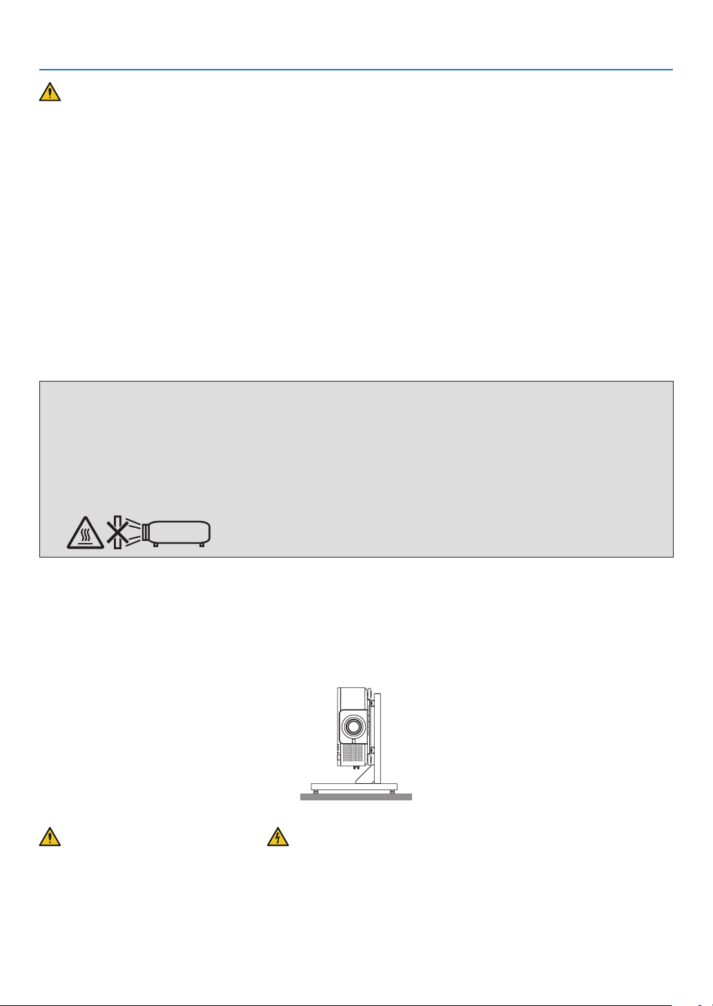
The below pictogram indicated on the cabinet means the precaution for avoiding to place objects in front of the
projector lens.
This projector can be installed any angle within vertical and horizontal 360° range, however, life of optical parts will
be shorten in the following installation state:
• When the projector is installed on which lens faces downward.
• When the intake vent on the projector side faces downward in the portrait installation. (→ page 137)
For portrait installation, install the projector with the intake vent at the bottom. Observe precautions for portrait installation.
* A customized stand is required to be attached to the projector. (→ page 138)
Fire and Shock Precautions
• Ensure that there is sufficient ventilation and that vents are unobstructed to prevent the build-up of heat inside your
projector. Allow enough space between your projector and a wall. (→ page xi)
• Do not try to touch the exhaust vent on the rear side (when seen from the front) as it can become heated while the
projector is turned on and immediately after the projector is turned off. Parts of the projector may become temporarily heated if the projector is turned off with the POWER button or if the AC power supply is disconnected during
normal projector operation.
Use caution when picking up the projector.
iii
Page 6
Important Information
• Prevent foreign objects such as paper clips and bits of paper from falling into your projector. Do not attempt to retrieve
any objects that might fall into your projector. Do not insert any metal objects such as a wire or screwdriver into your
projector. If something should fall into your projector, disconnect it immediately and have the object removed by a
qualied service personnel.
• Do not place any objects on top of the projector.
• Do not touch the power plug during a thunderstorm. Doing so can cause electrical shock or re.
• The projector is designed to operate on a power supply of 110-240V AC 50/60 Hz. Ensure that your power supply
ts this requirement before attempting to use your projector.
• Make sure to mount the power cord stopper before attempting to use your projector. Please refer to page 15 about
the power cord stopper.
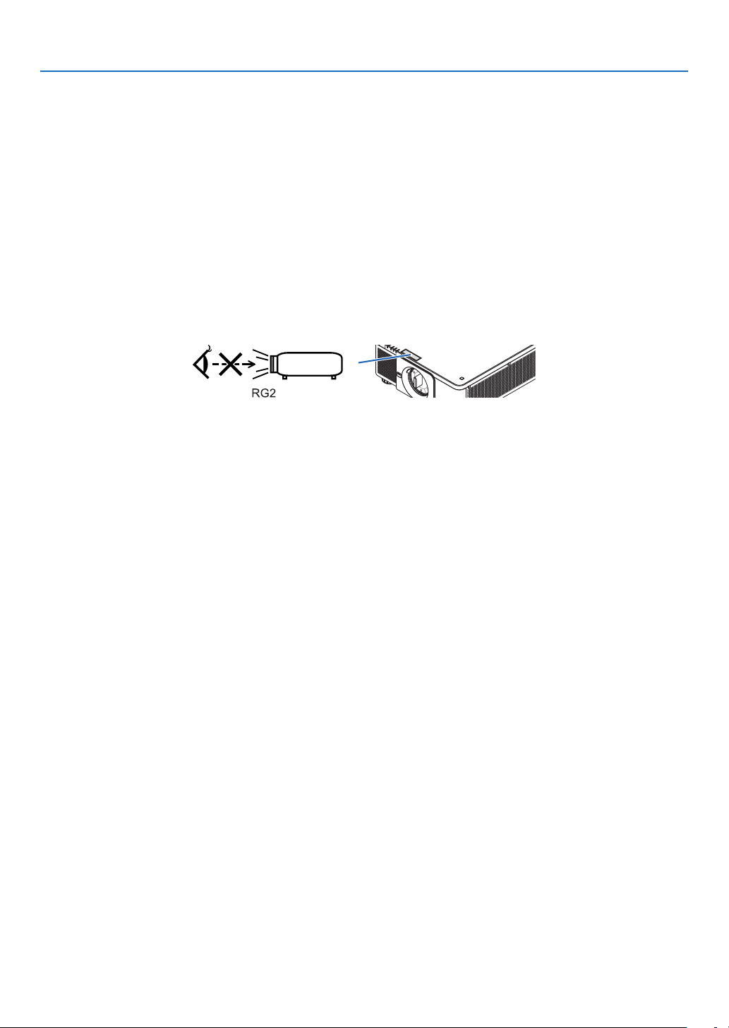
• Do not look into the light source using optical instruments (such as magnifying glasses and mirrors). Visual impairment could result.
• When turning on the projector, ensure that nobody is facing towards the lens in the path of the light emitted from the
laser. Do not look into the lens while the projector is on. Serious damage to your eyes could result. The following
label, that is indicated at the lens-mounting-section on the projector cabinet, describes this projector is categorized
in the risk group 2 of IEC 62471-5: 2015. As with any bright light source, do not stare into the beam, RG2 IEC
62471-5: 2015.
• Perform the adjustment from behind or from the side of the projector. Adjusting from the front could expose your
eyes to strong light which could injure them.
• Keep any items (magnifying glass etc.) out of the light path of the projector. The light path being projected from the
lens is extensive, therefore any kind of abnormal objects that can redirect light coming out of the lens, can cause
an unpredictable outcome such as a re or injury to the eyes.
• Do not place any objects, which are easily affected by heat, in front of a projector exhaust vent.
Doing so could lead to the object melting or getting your hands burned from the heat that is emitted from the exhaust
vent.
• Handle the power cord carefully. A damaged or frayed power cord can cause electric shock or re.
- Do not use any power cord other than the one supplied with the projector.
- Do not bend or tug the power cord excessively.
- Do not place the power cord under the projector, or any heavy object.
- Do not cover the power cord with other soft materials such as rugs.
- Do not heat the power cord.
- Do not handle the power plug with wet hands.
• Turn off the projector, unplug the power cord and have the projector serviced by a qualied service personnel under
the following conditions:
- When the power cord or plug is damaged or frayed.
- If liquid has been spilled into the projector, or if it has been exposed to rain or water.
- If the projector does not operate normally when you follow the instructions described in this user’s manual.
- If the projector has been dropped or the cabinet has been damaged.
- If the projector exhibits a distinct change in performance, indicating a need for service.
• Disconnect the power cord and any other cables before carrying the projector.
• Turn off the projector and unplug the power cord before cleaning the cabinet.
• Turn off the projector and unplug the power cord if the projector is not to be used for an extended period of time.
• When using a LAN cable:
For safety, do not connect to the terminal for peripheral device wiring that might have excessive voltage.
• Do not use the malfunctioned projector. It may cause of not only electric shock or re but also serious damage to
your eye sight.
• Do not let children to operate the projector by themselves. If the projector is operated by children, adults need to
attend and keep their eyes on children.
• If damage or malfunction of the projector is found, immediately stop to use it and consult your dealer for repair.
• Never disassemble, repair, and remodel by end users. If these are performed by end users, it may cause of serious
problem on users’ safety.
• Consult your dealer for disposing the projector. Never disassemble the projector before disposing it.
iv
Page 7
Important Information
CAUTION
• Keep hands away from the lens mounting portion while performing a lens shift. Failure to do so could result in
ngers being pinched by the moving lens.
• Do not use the tilt-foot for purposes other than originally intended. Misuses such as gripping the tilt-foot or hanging on the wall can cause damage to the projector.
• Select [HIGH] in Fan mode if you continue to use the projector for consecutive days. (From the menu, select
[SETUP] → [INSTALLATION(1)] → [FAN MODE] → [HIGH].)
• Do not unplug the power cord from the wall outlet or projector when the projector is powered on. Doing so can
cause damage to the AC IN terminal of the projector and (or) the prong plug of the power cord.
To turn off the AC power supply when the projector is powered on, use the projector’s main power switch, a
power strip equipped with a switch, or a breaker.
• When moving the projector, make sure you have at least two people. Attempting to move the projector alone
could result in back pain or other injuries.
Caution on Handling the Optional Lens
When shipping the projector with the lens, remove the lens before shipping the projector. Always attach the dust cap
to the lens whenever it is not mounted on the projector. The lens and the lens shift mechanism may encounter damage caused by improper handling during transportation.
Do not hold the lens part when carrying the projector.
Doing so could cause the focus ring to rotate, resulting in accidental dropping of the projector.
In the condition the projector is no lens mounted, do not put your hands in the lens mount opening for carrying the
projector.
For mounting, replacing, and cleaning the lens, make sure to power off the projector and disconnect the power cord.
Failure to do so can result in eye injury, electric shock, or burn injuries.
Keep hands away from the lens mounting portion while performing a lens shift. Failure to do so could result in ngers
being pinched by the moving lens.
Cable information
CAUTION
For HDMI, DisplayPort, BNC, LAN, and RS232C, please use a shielded cable.
Use of other cables may cause interference with radio and television reception.
v
Page 8

Important Information
Precautions when installing or replacing the lens unit sold separately (LENS
CALIBRATION)
After installing or replacing the lens unit, press either the CALIBRATION button on the main unit or the INFO/L-CALIB.
button while pressing the CTL button on the remote control to carry out [LENS CALIBRATION]. (→ page 17, 110)
By carrying out [LENS CALIBRATION], the adjustment range of the zoom, focus, and shift of the [LENS MEMORY]
is calibrated.
Contact your dealer to install and replace the lens unit.
Remote Control Precautions
• Handle the remote control carefully.
• If the remote control gets wet, wipe it dry immediately.
• Avoid excessive heat and humidity.
• Do not short, heat, or take apart batteries.
• Do not throw batteries into re.
• If you will not be using the remote control for a long time, remove the batteries.
• Ensure that you have the batteries’ polarity (+/−) aligned correctly.
• Do not use new and old batteries together, or use different types of batteries together.
• Dispose of used batteries according to your local regulations.
Light Module
1. A light module containing multiple laser diodes is equipped in the product as the light source.
2. These laser diodes are sealed in the light module. No maintenance or service is required for the performance of
the light module.
3. End user is not allowed to replace the light module.
4. Contact qualied distributor for light module replacement and further information.
Laser Safety Caution
• For USA
This product is classied as Class 3R of IEC 60825-1 Second edition 2007-03
Complies with FDA performance standards for laser products except for deviations pursuant to Laser Notice No.
50, dated June 24, 2007.
For other regions
This product is classied as Class 1 of IEC 60825-1 Third edition 2014-05 and EN 60825-1 Third edition 2014-08.
This product is classied as RG2 of IEC 62471-5 First edition 2015-06.
Obey the laws and regulations of your country in relation to the installation and management of the device.
• Outline of laser emitted from the built-in light module:
• Wave length: 450–460 nm
• Maximum power: 380 W
• Radiation pattern from the protective housing:
• Wave length: 450–460 nm
• Maximum laser radiation output: 0.253 mJ
• Pulse duration: 0.5 ms
• Repetition frequency: 240 Hz
• The laser module is equipped in this product. Use of controls or adjustments of procedures other than those speci-
ed herein may result in hazardous radiation exposure.
CAUTION
• Use of controls or adjustments or performance of procedures other than those specied herein may result in
hazardous radiation exposure.
CAUTION – CLASS 3R OF IEC 60825-1 SECOND EDITION LASER PRODUCT
LASER LIGHT – AVOID DIRECT EYE EXPOSURE
vi
Page 9
Important Information
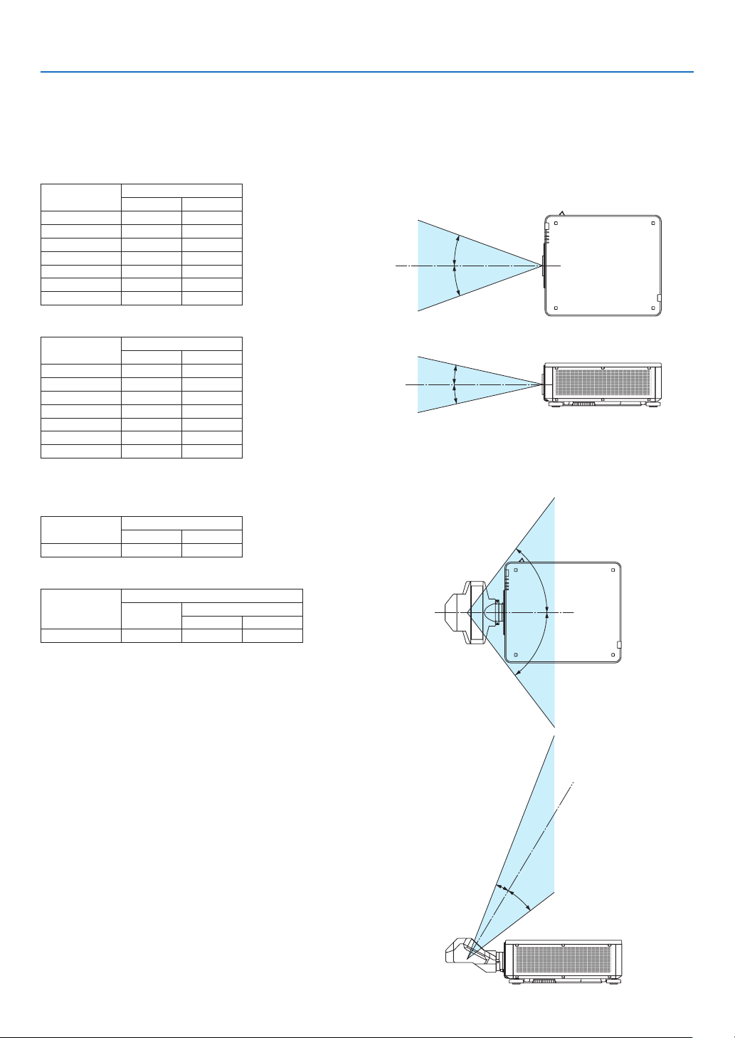
Laser light radiation range
The gure below shows the maximum radiation range of the laser light.
(unit: degree)
Applicable lens unit: NP16FL-4K/NP17ZL-4K/NP18ZL-4K/NP19ZL-4K/NP20ZL-4K/NP21ZL-4K/NP31ZL-4K
Horizontal angle H
Lens Zoom
NP16FL-4K — 32.6
NP17ZL-4K 15.5 21.6
NP18ZL-4K 12.3 16.0
NP19ZL-4K 7.7 12.6
NP20ZL-4K 5.3 7.9
NP21ZL-4K 3.4 5.4
NP31ZL-4K 27.6 33.2
Vertical angle V
Lens Zoom
NP16FL-4K — 19.7
NP17ZL-4K 8.9 12.5
NP18ZL-4K 7.0 9.1
NP19ZL-4K 4.3 7.1
NP20ZL-4K 3.0 4.5
NP21ZL-4K 1.9 3.0
NP31ZL-4K 16.4 20.2
Tele Wide
H
H
Tele Wide
V
V
Applicable lens unit: NP39ML-4K
Horizontal angle H
Lens Zoom
Tele Wide
NP39ML-4K — 53.0
Vertical angle V
Lens Zoom
Tele Wide
V1 V2
NP39ML-4K — 9.5 18.8
H
H
1
V
2
V
vii
Page 10
Important Information
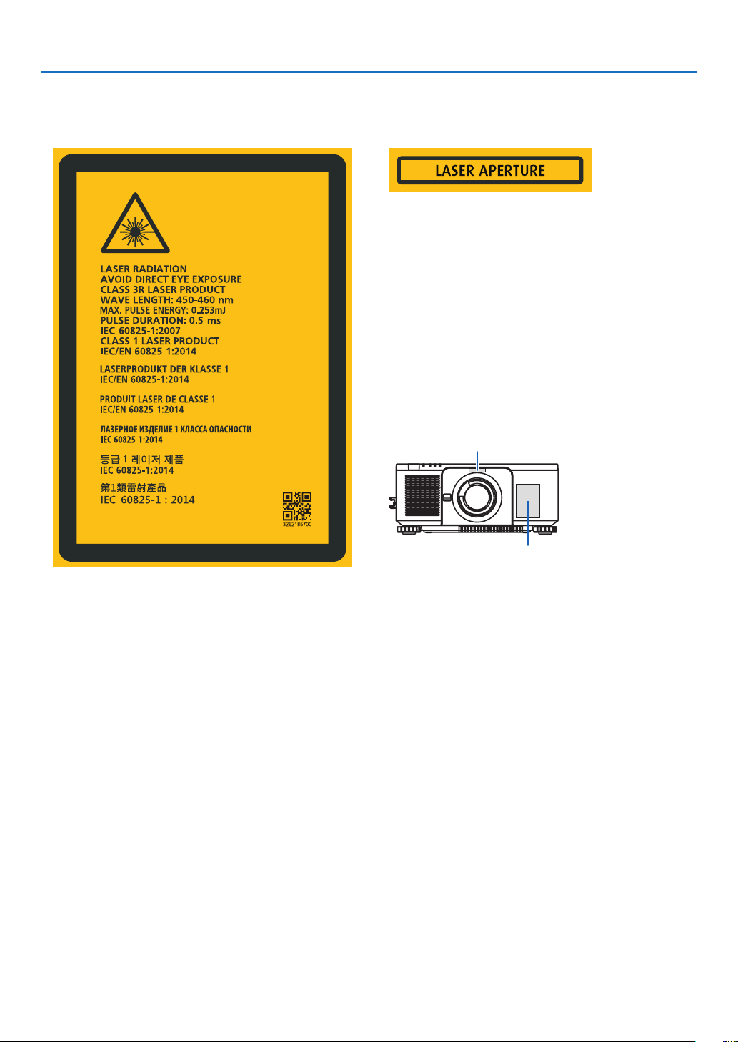
• These labels of the LASER PRODUCT in CLASS 3R conforming to IEC 60825-1 Second edition, and in Class 1
conforming to IEC 60825-1 Third edition are stuck on the below indicated positions.
Label 1 Label 2
Label 2
Label 1
viii
Page 11
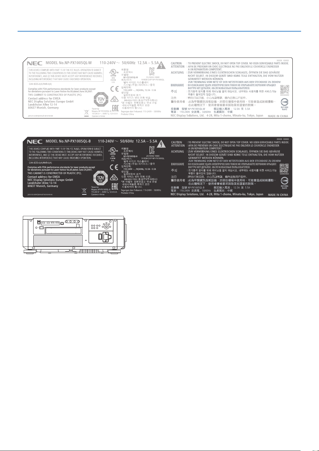
• Manufacturer's ID Label
(For PX1005QL-W)
(For PX1005QL-B)
Important Information
Position of the Manufacturer's ID Label
ix
Page 12

Important Information
About Copyright of original projected pictures:
Please note that using this projector for the purpose of commercial gain or the attraction of public attention in a venue
such as a coffee shop or hotel and employing compression or expansion of the screen image with the following functions may raise concern about the infringement of copyrights which are protected by copyright law:
[ASPECT RATIO], [KEYSTONE], Magnifying feature and other similar features.
x
Page 13
Important Information
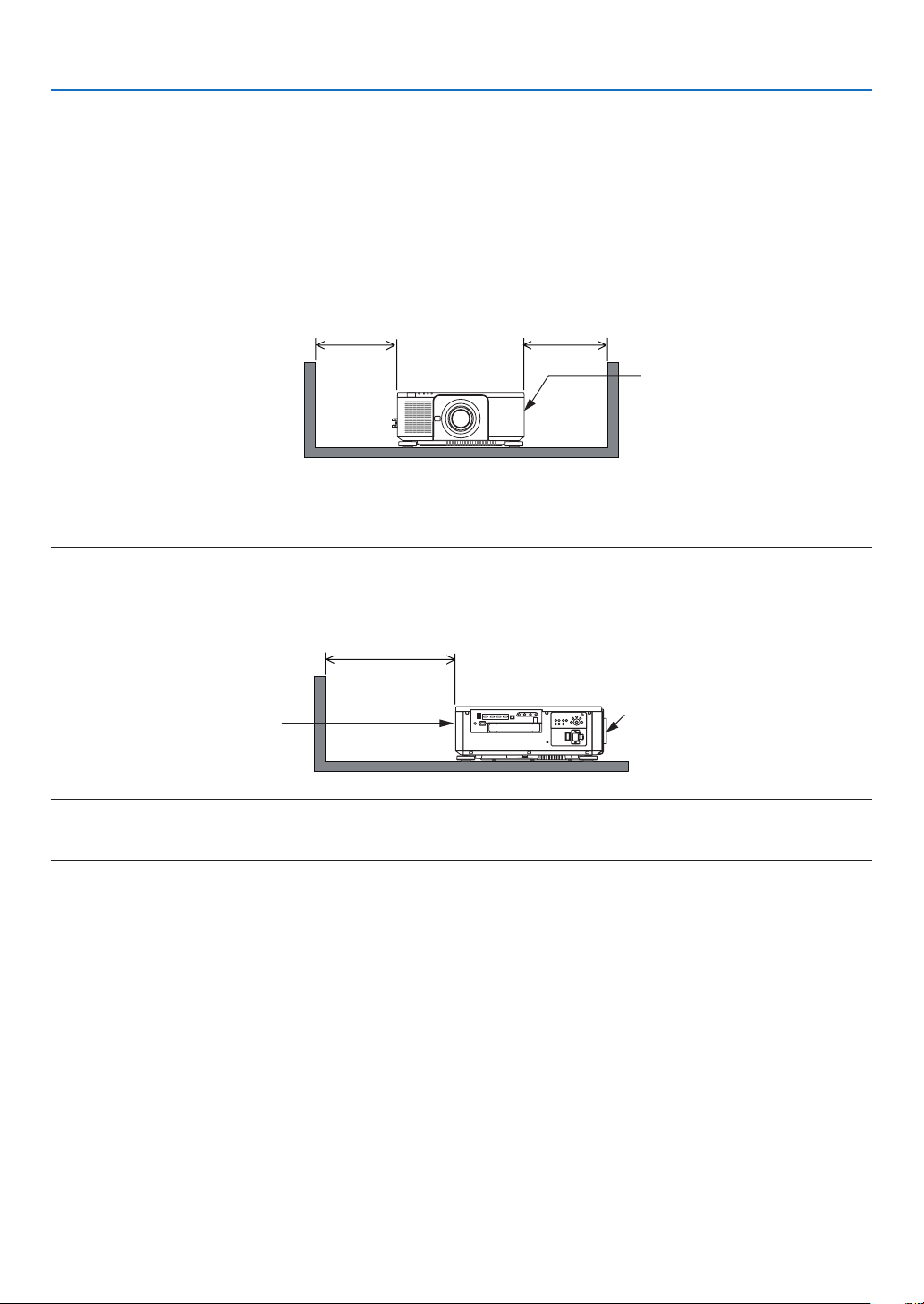
Clearance for Installing the Projector
Allow ample clearance between the projector and its surroundings as shown below.
The high temperature exhaust coming out of the device may be sucked into the device again.
Avoid installing the projector in a place where air movement from the HVAC is directed at the projector.
Heated air from the HVAC can be taken in by the projector’s intake vent. If this happens, the temperature inside the
projector will rise too high causing the over-temperature protector to automatically turn off the projectors power.
• Concerning to the portrait projection, please refer “Portrait projection” on page 137.
Example 1 – If there are walls on both sides of the projector.
30 cm/11.8" or greater 30 cm/11.8" or greater
Intake vent
NOTE:
• The drawing shows the proper clearance required for the left and right of the projector assuming sufficient clearance has been
kept for the front, back and top of the projector.
Example 2 – If there is a wall behind the projector.
50 cm/19.7" or greater
Lens
Exhaust vent
NOTE:
• The drawing shows the proper clearance required for the back of the projector assuming sufficient clearance has been kept for
the right, left and top of the projector.
xi
Page 14

Table of Contents
Important Information ............................................................................................ i
1. Introduction ...........................................................................................................1
❶ What’s in the Box? ..........................................................................................................1
❷ Introduction to the Projector ............................................................................................3
❸ Part Names of the Projector ...........................................................................................6
❹ Part Names of the Remote Control ............................................................................... 10
2. Projecting an Image (Basic Operation) ...............................................13
❶ Flow of Projecting an Image .........................................................................................13
❷ Connecting Your Computer/Connecting the Power Cord ..............................................14
❸ Turning on the Projector ................................................................................................ 16
❹ Selecting a Source .......................................................................................................19
❺ Adjusting the Picture Size and Position ........................................................................22
❻ Turning off the Projector ................................................................................................33
❼ After Use .......................................................................................................................34
3. Convenient Features ......................................................................................35
❶ Turn off the light of the projector (LENS SHUTTER) .....................................................35
❷ Turning off the Image (AV-MUTE) .................................................................................35
❸ Turning Off the On-Screen Menu (On-Screen Mute) ....................................................35
❹ Shift the On-Screen Menu displaying position ..............................................................36
❺ Freezing a Picture .........................................................................................................37
❻ Magnifying a Picture .....................................................................................................38
❼ Adjustment of luminance (brightness) and energy-saving effect ..................................39
❽ Correcting Horizontal and Vertical Keystone Distortion [CORNERSTONE] ..................43
❾ Preventing the Unauthorized Use of the Projector [SECURITY] ...................................46
❿ Controlling the Projector by Using an HTTP Browser ...................................................49
⓫ Storing Changes for Lens Shift, Zoom, and Focus [LENS MEMORY]..........................51
4. Multi-Screen Projection ...............................................................................57
❶ Things that can be done using multi-screen projection ................................................57
❷ Using a single projector to project two or four types of videos at the same time
[PICTURE BY PICTURE] ........................................................................................58
❸ Line up multiple projectors to display a high resolution image in a larger screen
[TILING] ..................................................................................................................60
❹ Adjust boundaries of a projected image [EDGE BLENDING] .......................................64
xii
Page 15

Table of Contents
5. Using On-Screen Menu .................................................................................71
❶ Using the Menus ...........................................................................................................71
❷ Menu Elements .............................................................................................................72
❸ List of Menu Items ........................................................................................................73
❹ Menu Descriptions & Functions [INPUT] ......................................................................79
❺ Menu Descriptions & Functions [ADJUST] ...................................................................83
❻ Menu Descriptions & Functions [DISPLAY] ..................................................................95
❼ Menu Descriptions & Functions [SETUP] ...................................................................105
❽ Menu Descriptions & Functions [INFO.] .....................................................................129
6. Installation and Connections .................................................................. 133
❶ Mounting a lens (sold separately) ...............................................................................133
❷ Connecting to Other Equipment .................................................................................135
❸ Portrait projection (vertical orientation) ....................................................................... 137
❹ Stacking projectors .....................................................................................................139
7. Maintenance .....................................................................................................142
❶ Cleaning the Lens.......................................................................................................142
❷ Cleaning the Cabinet
.................................................................................................. 142
8. Appendix ..............................................................................................................143
❶ Throw distance and screen size .................................................................................143
❷ Mounting the Optional Board (sold separately) ..........................................................147
❸ Compatible Input Signal List .......................................................................................149
❹ Specications .............................................................................................................151
❺ Cabinet Dimensions ...................................................................................................154
❻ Pin assignments and signal names of main terminals................................................155
❼ About the ASCII Control Command ............................................................................ 157
❽ Changing the Background Logo (Virtual Remote Tool) ...............................................159
❾ Troubleshooting ..........................................................................................................160
❿ PC Control Codes and Cable Connection ..................................................................167
⓫ Troubleshooting Check List ......................................................................................... 168
xiii
Page 16
1. Introduction
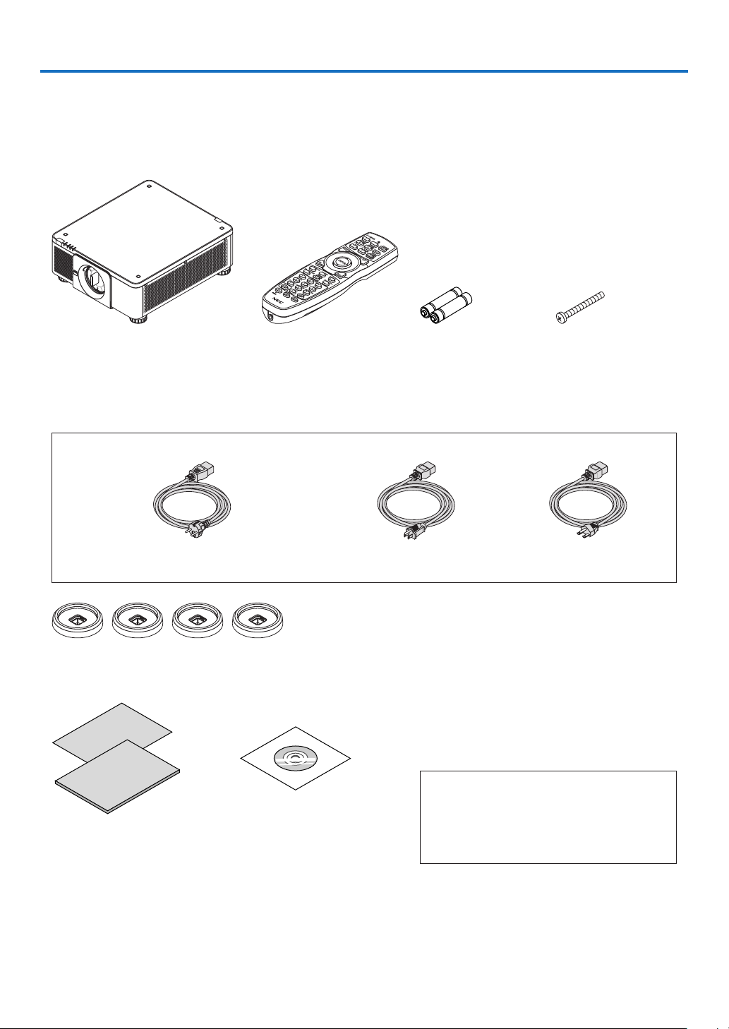
❶ What’s in the Box?
Make sure your box contains everything listed. If any pieces are missing, contact your dealer.
Please save the original box and packing materials if you ever need to ship your projector.
Projector
Dust cap for lens
* The projector is shipped without
a lens. For the types of lens and
throw distances, see page 143.
Power cord × 3
(79TM1021) (79TQ1001 for AC 120 V) (79TQ1011 for AC 200 V)
For Europe/Asia/South America For North America
4 Stacking holders (79TM1101)
When stacking projectors (double stacking), the tilt foot of the upper projector will be placed onto these stacking holders. (→
page 139)
Remote control
(7N901041)
AA alkaline batteries
(x2)
Lens theft prevention
screw (79TM1071)
This screw makes it difcult to remove the lens
mounted on the projector. ( → page 134)
• Important Infomation
(7N8N9041)
• Quick Setup Guide (For North
America: 7N8N9051) (For Other
countries than North America:
7N8N9051 and 7N8N9061)
• Security Sticker
(Use this sticker when security
password is set on.)
NEC Projector CD-ROM
User’s manual (PDF)
(7N952732)
For North America only
Limited warranty
For customers in Europe:
You will nd our current valid Guarantee Policy
on our Web Site:
https://www.nec-display-solutions.com
1
Page 17

Removing/Attaching the Dust Cap
To remove the dust cap from the projector, push the
tongue at the top left outward and pull the knob at the
center of the cap.
1. Introduction
To attach the dust cap to the projector, locate the catch
on the lower end of the dust cap and place it into the
opening of the projector with the point of a triangle mark
(▽) facing downward (① in the gure below), and then
push the upper end of the dust cap against the projector to place the catches into the slot while clutching the
handle (② in the gure below).
2
Page 18

1. Introduction
❷ Introduction to the Projector
This section introduces you to your new projector and describes the features and controls.
General
• Single-chip DLP projector with high resolution and high brightness
Realized to project the image in the resolution 3840 × 2160 pixels (4K UHD), the aspect ratio in 16:9, and the
brightness in 10000 lumens.
• Superior dust-proof structure
Adapted the cycle cooling system for cooling down the optical parts. By this system, air in the light source is cooled
down and circulated. As the result, the optical parts are not exposed to the open air and enable to keep brightness
without contamination by dust.
* Can not prevent contamination by dust completely.
Light source · Brightness
• A long-life laser diode is equipped in the light module
The product can be operated at low cost because the laser light source can be used for a long time without requir-
ing replacement or maintenance.
• Brightness can be adjusted within a wide range
Unlike with ordinary light sources, the brightness can be adjusted from 20 to 100% in 1% increments.
• [CONSTANT BRIGHTNESS] mode
Brightness normally decreases with use, but by selecting [CONSTANT BRIGHTNESS] mode, sensors inside the
projector detect and automatically adjust the output, thereby maintaining constant brightness throughout the life
of the light module.
However, if brightness output is set at the maximum, brightness will decrease with use.
Installation
• Wide range of optional lenses selectable according to the place of installation
This projector supports 8 types of optional lenses, providing a selection of lenses adapted to a variety of places
of installation and projection methods.
In addition, the lenses can be mounted and removed in one touch.
Note that no lens is mounted upon shipment from the factory. Please purchase optional lenses separately.
• This projector can be installed any angle within vertical and horizontal 360° range, however, life of optical
parts will be shorten in the following installation state:
• When the projector is installed on which lens faces downward.
• When the intake vent on the projector side faces downward in the portrait installation.
• Double stackable for high light output projection
By stacking 2 projectors, increased brightness on a large screen is possible.
• Power lens control for quick and easy adjustment
By using buttons on the projector or the remote control, zoom, focus, and position (lens shift) can be adjusted.
3
Page 19

1. Introduction
Videos
• High quality pictures using Cinema Quality Picture technology
The device displays high-resolution pictures with its rich gradation expression capability and by improving the
contrast in the picture boundary area using the development technology for digital cinema projectors and the
unique NEC video processor for image processing.
• A variety of input terminals such as HDMI, DisplayPort, HDBaseT, SDI, etc.
The projector is equipped with HDMI (1/2), DisplayPort (1/2), HDBaseT, SDI (1/2/3/4) input terminals. Moreover,
You can install optional boards (sold separately) to SLOT.
The projector’s HDMI input terminals and DisplayPort input terminals support HDCP.
HDBaseT, promoted and advanced by the HDBaseT Alliance, is a consumer electronic (CE) and commercial
connectivity technology.
• Displaying two or four images at the same time (PICTURE BY PICTURE)
With this single projector you can project two or four images at the same time.
When projecting two images, you can adjust its position on the screen. The projector also supports the portrait
projection.
• Multi-screen projection using multiple projectors
You can line up multiple projectors to display a high resolution image in a larger screen.
Furthermore, the boundaries of the screens are smoothed using an edge blending function.
• Slot for optional board
This projector has a slot for optional boards (sold separately).
Network
• Supports wired LAN
Equips the LAN and HDBaseT (RJ-45) ports. Utilizing a wired LAN connected with these ports, it enables to control
the projector by a computer.
• Convenient utility software (User Supportware)
This projector supports our utility software (NaViSet Administrator 2, Virtual Remote Tool, etc.).
NaViSet Administrator 2 helps you control the projector by a computer via wired LAN connection.
Virtual Remote Tool helps you perform operations by a virtual remote control such as projector's power on or off
and signal selection via wired LAN connection. Moreover, it has function to send an image to the projector and
register it as the logo data.
Please visit our web site for downloading each software.
URL: https://www.nec-display.com/dl/en/index.html
• CRESTRON ROOMVIEW and Extron XTP compatibility
The projector supports CRESTRON ROOMVIEW and Extron XTP, allowing multiple devices connected in the
network to be managed and controlled from a computer. Moreover, it enables to output and control image via an
Extron XTP transmitter connected with the projector.
4
Page 20

1. Introduction
About this user’s manual
The fastest way to get started is to take your time and do everything right the rst time. Take a few minutes now to
review the user’s manual. This may save you time later on. At the beginning of each section of the manual you’ll nd
an overview. If the section doesn’t apply, you can skip it.
5
Page 21
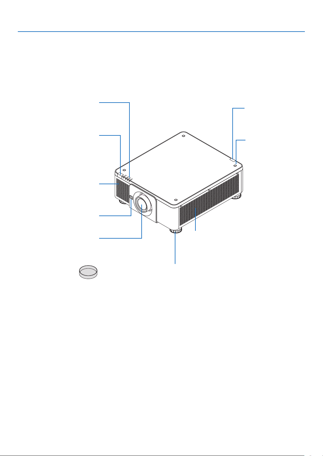
❸ Part Names of the Projector
Front/Top
The lens is sold separately. The description below is for when the NP18ZL-4K lens is mounted.
1. Introduction
Indicator Panel
(→ page 8)
Remote Sensor (located on the
front and the rear)
(→ page 12)
Takes in air to cool the unit.
(→ page xi, 142)
Lens Release (LENS) Button
(→ page 134)
Lens Cap
(The lens cap is attached
to the lens.)
Intake vent
Lens
Remote Sensor
(→ page 12)
Stacking Holder xing
section
(4 locations)
Intake vent
Takes in air to cool the unit.
(→ page xi, 142)
Tilt Foot
(→ page 32)
6
Page 22
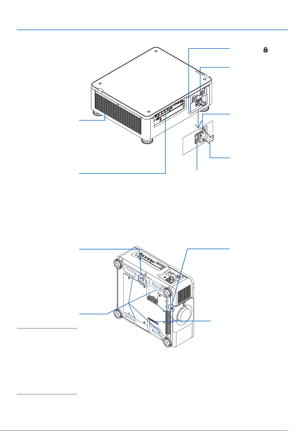
Rear
1. Introduction
Heated aiir is exhausted
Exhaust vent
from here.
(→ page xi, 142)
Terminals
(→ page 9)
Main power switch
While AC power is being supplied, set the
main power switch to ON position (|), then
your projector will enter a standby state.
* Security and theft protection lock compatible with Kensington security cables/equipment.
For products, visit Kensington’s website.
Security Slot (
Controls
(→ page 8)
AC IN terminal
Connect the supplied
power cord’s three-pin
plug here, and plug the
other end into an active
wall outlet. (→ page 14)
Power Cord Stopper
(→ page 15)
)*
Fixing a theft prevention
Security Bar
device.
The security bar accepts
security wires or chains
up to 0.18 inch/4.6 mm in
diameter.
Handle (located on 4 posi-
tions)
For transportation
NOTE:
• For moving the projector,
make sure you have at least
two people. At the same
time, do not grip and hold
the projector other than by
these handles. Attempting
to move the projector alone
could result in back pain or
other injuries.
Theft prevention screw
hole for the lens unit
Intake vent
Takes in air to cool the unit.
(→ page xi, 142)
7
Page 23
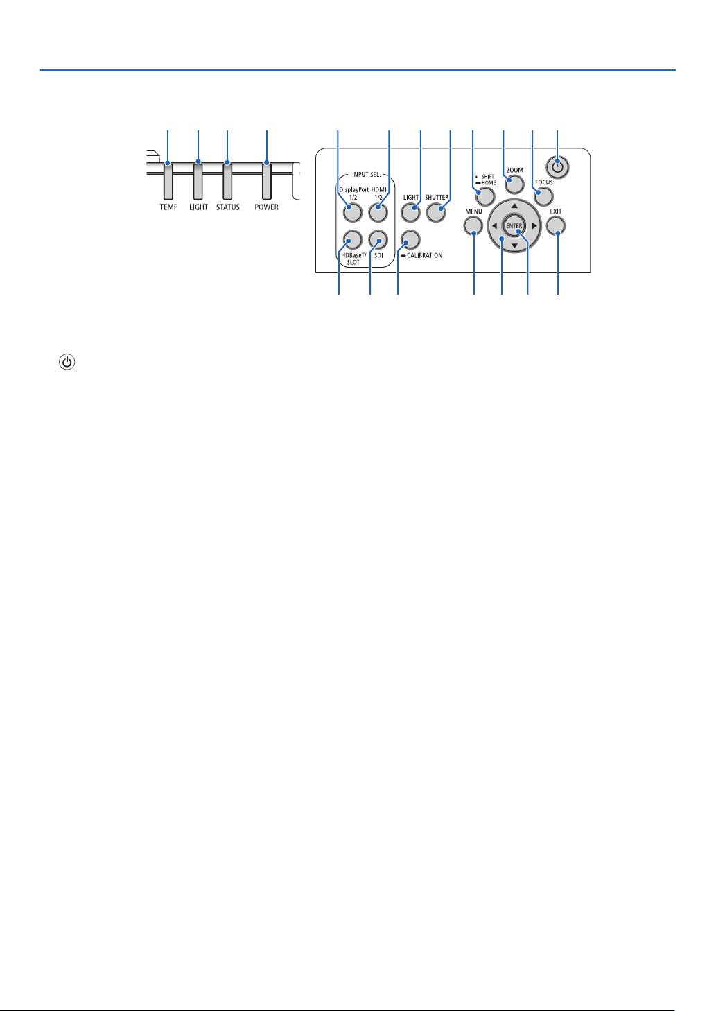
Controls/Indicator Panel
5 4 3 2 16
1. Introduction
18 1517
7
14 16
1. (POWER) Button
(→ page 17, 33)
2. POWER Indicator
(→ page 17, 33, 160)
3. STATUS Indicator
(→ page 160)
4. LIGHT Indicator
(→ page 160)
5. TEMP. Indicator
(→ page 41, 162)
6. HDMI 1/2 Button
(→ page 19)
7. DisplayPort 1/2 Button
(→ page 19)
8. HDBaseT/SLOT Button
(→ page 19)
9. SDI Button
(→ page 19)
10. MENU Button
(→ page 71)
11. ▲▼◀▶ Buttons
(→ page 71)
12. ENTER Button
(→ page 71)
13. EXIT Button
(→ page 71)
14. SHIFT/HOME Button
(→ page 23)
15. ZOOM Button
(→ page 31)
16. FOCUS Button
(→ page 26)
9 12 13
8
19
17. LIGHT Button
(→ page 39)
18. SHUTTER Button
(→ page 35)
19. CALIBRATION Button
(→ page 17, 110)
10 11
8
Page 24
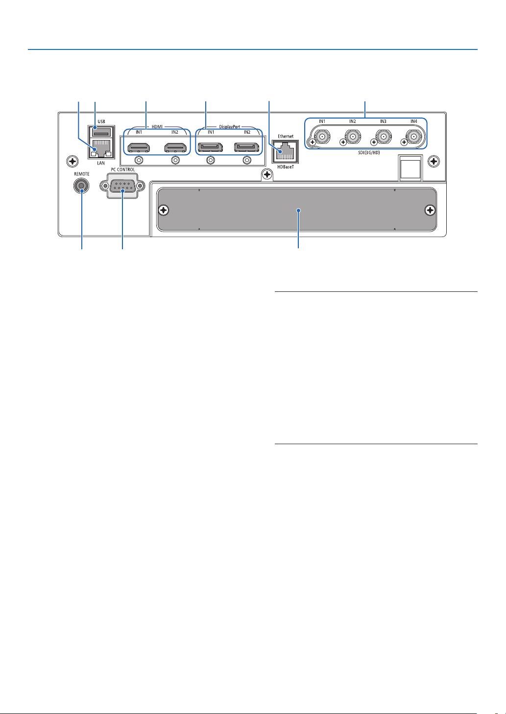
Terminals Features
1. Introduction
6
7
1. HDMI1 IN/HDMI2 IN Terminal [HDMI IN1/IN2]
(Type A)
(→ page 135)
2. DisplayPort1 IN/DisplayPort2 IN Terminal
[DisplayPort IN1/IN2] (DisplayPort 20 Pin)
(→ page 135)
3. HDBaseT Port [Ethernet/HDBaseT] (RJ-45)
(→ page 135)
4. SDI1/SDI2/SDI3/SDI4 IN Terminal [SDI(3G/HD)
IN1/IN2/IN3/IN4] (BNC)
(→ page 135)
5. USB Port (Type A)
(For future expansion. This port allows for power sup-
ply.)
6. LAN port [LAN] (RJ-45)
The port for controlling the projector from a PC via
a network. Connect the projector and the PC with a
shielded twisted pair (STP) cable of Category 5e or
higher (sold commercially).
7. REMOTE Terminal (Stereo Mini)
Use this jack for wired remote control of the projector
using a commercially available remote cable with ⌀3.5
stereo mini-plug (without resistance).
Connect the projector and the supplied remote control
using a commercially available wired remote control
cable.
(→ page 12)
1 2
8
35
4
9
NOTE:
• When a remote control cable is connected to the REMOTE
terminal, infrared remote control operations cannot be
performed.
• Power cannot be supplied from the REMOTE terminal to
the remote control.
• When [HDBaseT] is selected in the [REMOTE SENSOR]
and the projector is connected to a commercially-available
transmission device that supports HDBaseT, remote
control operations in infra-red cannot be carried out if
transmission of remote control signals has been set up in
the transmission device. However, remote control using
infrared rays can be carried out when the power supply
of the transmission device is switched off.
8. PC CONTROL Port (D-Sub 9 Pin)
Use this port to connect a PC or control system.
This enables you to control the projector using serial
communication protocol. Use a shielded RS232C
cable (sold commercially). If you are writing your own
program, typical PC control codes are on page 167.
9. SLOT
(→ page 147)
9
Page 25
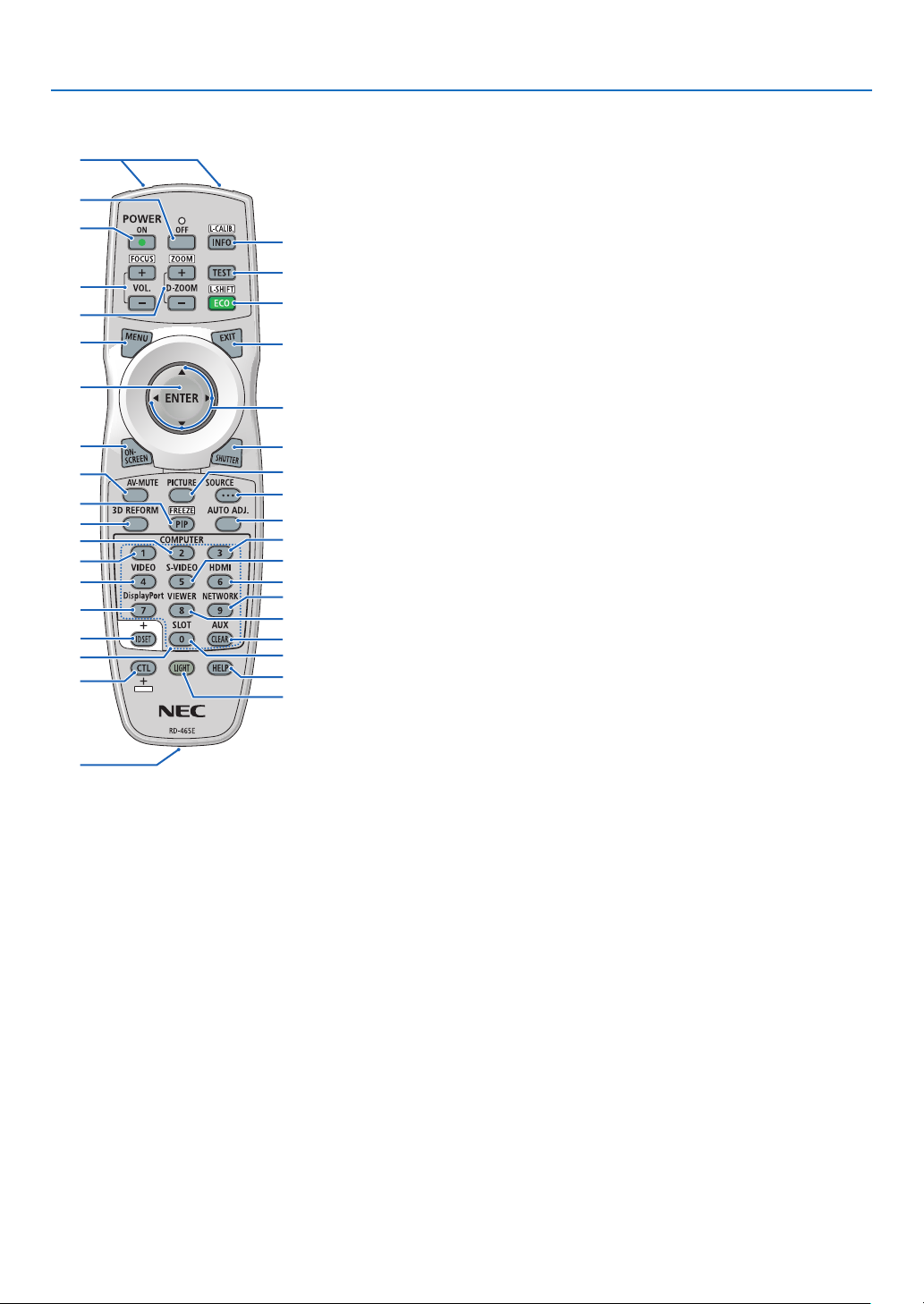
❹ Part Names of the Remote Control
1
1. Introduction
4
3
6
7
10
12
14
16
20
19
23
22
25
28
33
34
35
2
1. Infrared Transmitter
(→ page 12)
2. Remote Jack
Connect a commercially available
remote cable here for wired operation. (→ page 12)
3. POWER ON Button
(→ page 17)
4. POWER OFF Button
(→ page 33)
5. INFO/L-CALIB. Button
Display the [SOURCE(1)] screen
of the on-screen menu.
(→ page 129)
[LENS CALIBRATION] of the lens
unit is carried out when you press
the CTL button at the same time.
(→ page 17, 110)
6. VOL./FOCUS +/− Buttons
(The VOL. button function cannot
be used with this series of projectors.)
5
(→ page 26)
7. D-ZOOM/ZOOM +/− Buttons
8
(→ page 38, 31)
9
8. TEST Button
(→ page 79)
11
9. ECO/L-SHIFT Button
(→ page 39, 25)
13
10. MENU Button
(→ page 71)
15
11. EXIT Button
17
(→ page 71)
18
12. ENTER Button
21
(→ page 71)
24
13. ▲▼◀▶ Button
26
(→ page 71)
27
30
14. ON-SCREEN Button
29
(→ page 35)
32
15. SHUTTER Button
31
(→ page 35)
37
36
16. AV-MUTE Button
(→ page 35)
17. PICTURE Button
(→ page 83, 86)
18. SOURCE Button
(→ page 20)
19. 3D REFORM Button
(→ page 43)
20. PIP/FREEZE Button
(→ page 37)
21. AUTO ADJ. Button
When projecting the HDMI, Dis-
playPort, HDBaseT, SDI or SLOT
screen, the conditions are automatically adjusted to an optimum
state.
22, 23, 24. COMPUTER 1/2/3
Button
(not available on this series of
projectors)
25. VIDEO Button
(not available on this series of
projectors)
26. S-VIDEO Button
(not available on this series of
projectors)
27. HDMI Button
(→ page 19)
28. DisplayPort Button
(→ page 19)
29. VIEWER Button
(not available on this series of
projectors)
30. NETWORK Button
(→ page 19)
31. SLOT Button
(→ page 19)
32. AUX Button
(→ page 19)
33. ID SET Button
(→ page 116)
34. Numeric (0 to 9/CLEAR)
Buttons
(→ page 116)
35. CTL Button
This button is used in conjunction
with other buttons, similar to a
CTRL key on a computer.
36. LIGHT Button
This button is used to turn on the
backlight for the remote control
buttons.
The backlight will turn off if no
button operation is made for 10
seconds.
37. HELP Button
(→ page 129)
10
Page 26
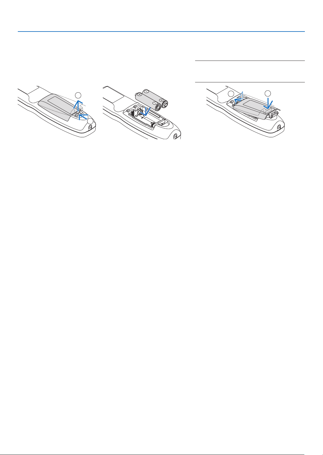
Battery Installation
1. Press the catch and remove
the battery cover.
2. Install new ones (AA). Ensure that you have the batteries’ polarity (+/−) aligned
correctly.
1. Introduction
3. Slip the cover back over the batteries until
it snaps into place.
NOTE:
• Do not mix different types of batteries or new
and old batteries.
2
1
1
Remote Control Precautions
• Handle the remote control carefully.
• If the remote control gets wet, wipe it dry immediately.
• Avoid excessive heat and humidity.
• Do not short, heat, or take apart batteries.
• Do not throw batteries into re.
• If you will not be using the remote control for a long time, remove the batteries.
• Ensure that you have the batteries’ polarity (+/−) aligned correctly.
• Do not use new and old batteries together, or use different types of batteries together.
• Dispose of used batteries according to your local regulations.
2
11
Page 27
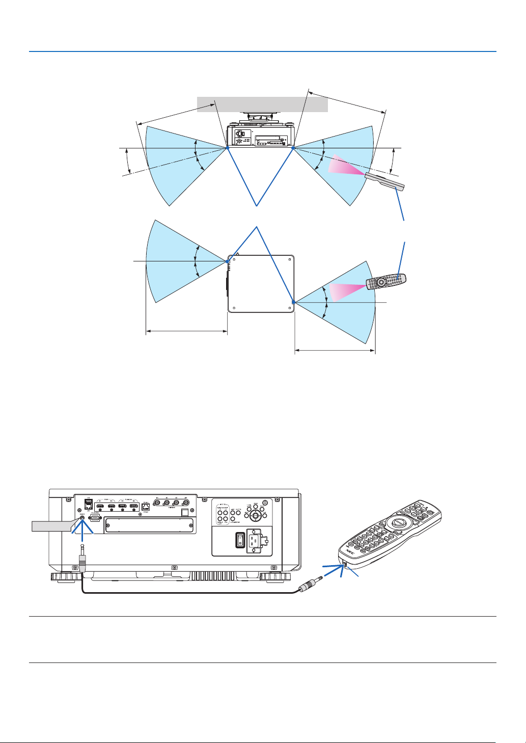
Operating Range for Wireless Remote Control
7 m/276 inch
1. Introduction
7 m/276 inch
15°
30°
30°
Remote sensor on projector cabinet
30°
30°
7 m/276 inch
30°
30°
30°
30°
7 m/276 inch
15°
Remote control
• The infrared signal operates by line-of-sight up to a distance of above meters and within a 60-degree angle of the
remote sensor on the projector cabinet.
• The projector will not respond if there are objects between the remote control and the sensor, or if strong light falls
on the sensor. Weak batteries will also prevent the remote control from properly operating the projector.
Using the Remote Control in Wired Operation
Connect one end of the remote cable to the REMOTE terminal and the other end to the remote jack on the remote
control.
REMOTE
Remote Jack
NOTE:
• When a remote cable is inserted into the REMOTE terminal, the remote control does not work for infrared wireless communication.
• Power will not be supplied to the remote control by the projector via the REMOTE jack. Battery is needed when the remote control
is used in wired operation.
12
Page 28

2. Projecting an Image (Basic Operation)
This section describes how to turn on the projector and to project a picture onto the screen.
❶ Flow of Projecting an Image
Step 1
• Connecting your computer / Connecting the power cord (→ page 14)
Step 2
• Turning on the projector (→ page 16)
Step 3
• Selecting a source (→ page 19)
Step 4
• Adjusting the picture size and position (→ page 22)
• Correcting keystone distortion [CORNERSTONE] (→ page 43)
Step 5
• Adjusting a picture
Step 6
• Making a presentation
Step 7
• Turning off the projector (→ page 33)
Step 8
• After use (→ page 34)
13
Page 29
2. Projecting an Image (Basic Operation)
❷ Connecting Your Computer/Connecting the Power Cord
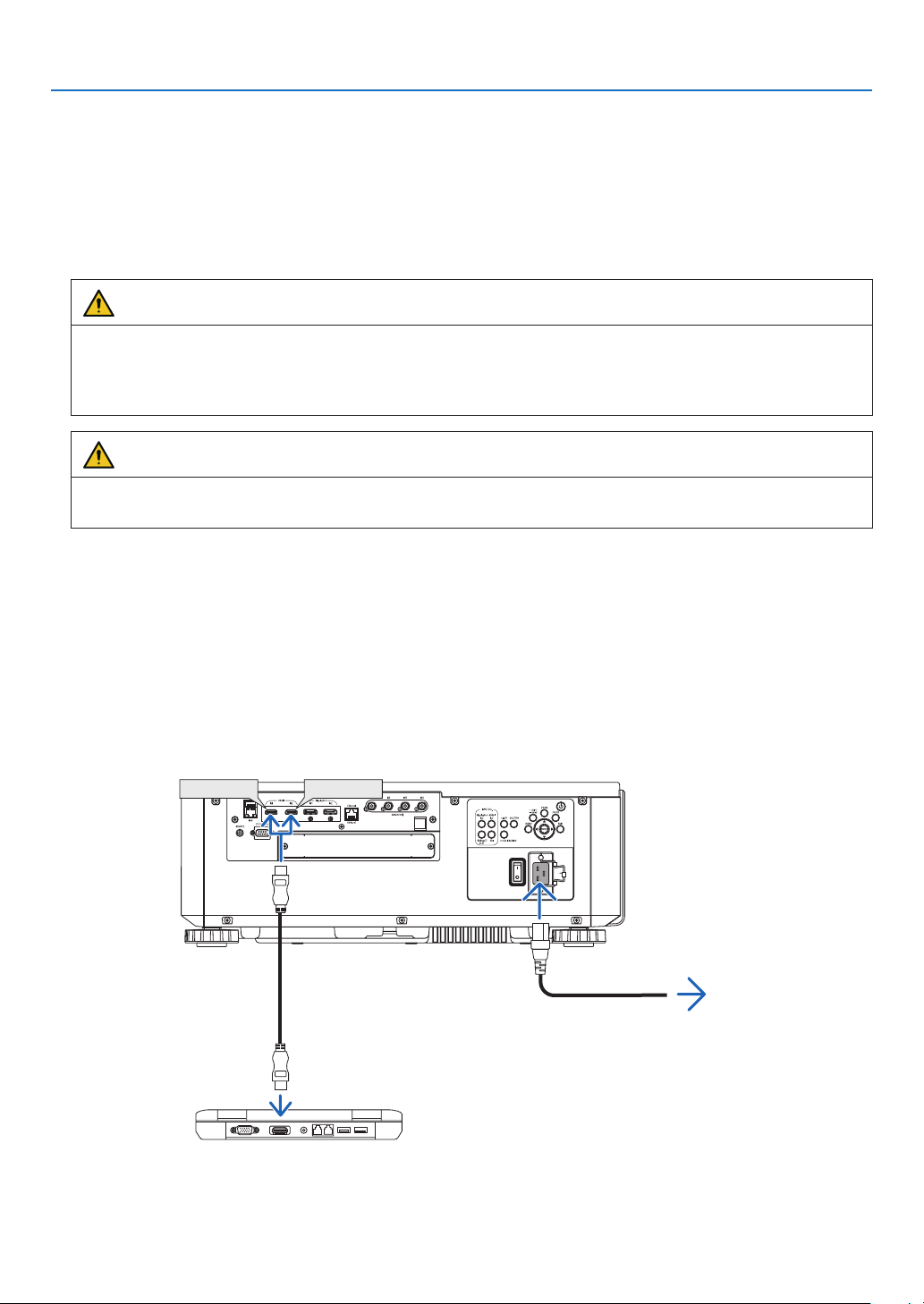
1. Connect your computer to the projector.
This section will show you a basic connection to a computer. For information about other connections, see “6-2.
Connecting to Other Equipment” on page 135.
Connect the HDMI output terminal of the computer to the HDMI1 or HDMI2 input terminal of the unit.
2. Connect the supplied power cord to the projector.
WARNING
MAKE SURE TO TAKE THE GROUND CONNECTION FOR THE DEVICE.
TO PREVENT FIRE OR SHOCK, DO NOT EXPOSE THIS UNIT TO RAIN OR MOISTURE.
DO NOT USE THIS UNIT'S PLUG WITH AN EXTENSION CORD OR IN AN OUTLET UNLESS ALL THE
PRONGS CAN BE FULLY INSERTED.
CAUTION
This equipment is designed to be used in the condition of the power cord connected to earth. If the power cord
is not connected to the earth, it may cause electric shock. Please make sure the power cord is earthed properly.
Important Information:
• When plugging in or unplugging the supplied power cord, make sure that the main power switch is pushed
to the off [O] position. Failure to do so may cause damage to the projector.
• Do not use a three-phase power supply. Doing so may cause of malfunction.
First connect the supplied power cord’s three-pin plug to the AC IN terminal of the projector, and then connect
the other plug of the supplied power cord in the wall outlet. Do not use any plug converter.
HDMI IN1 HDMI IN2
HDMI cable (with ferrite core)
(sold commercially)
To wall outlet
Make sure that the prongs are fully inserted into
both the AC IN terminal and the wall outlet.
14
Page 30
2. Projecting an Image (Basic Operation)
CAUTION
Parts of the projector may become temporarily heated if the projector is turned off with the POWER button or if the
AC power supply is disconnected during normal projector operation.
Use caution when picking up the projector.
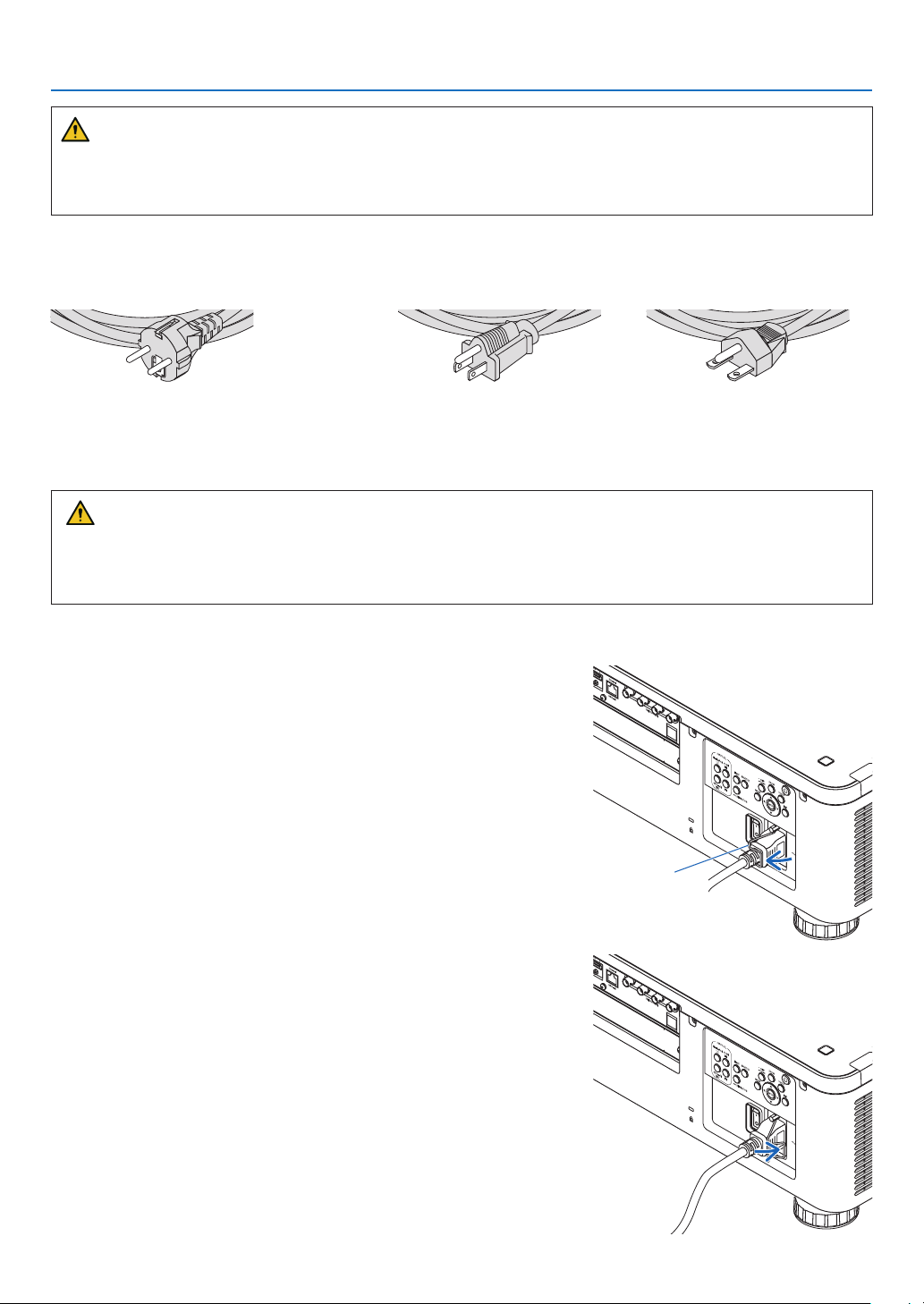
Using the Supplied Power Cords
Select the power cord suitable for your country or region.
For Europe/Asia/South America For North America
(120 V) (200 V)
Using the Power Cord Stopper
To prevent the power cord from accidently removing from the AC IN of the projector, attach the power cord stopper
to clamp the power cord.
CAUTION
• To prevent the power cord from coming loose, make sure that all the prongs of the power cord are fully inserted
into the AC IN terminal of the projector before using the power cord stopper to x the power cord. A loose
contact of the power cord may cause a re or electric shock.
Attaching the power cord stopper
1. Raise up the power cord stopper and lay it over the power cord.
• For releasing the stopper, raise up the stopper and lay it down to
the opposite side.
Power cord
stopper
15
Page 31
2. Projecting an Image (Basic Operation)
❸ Turning on the Projector
NOTE:
• The projector has two power switches: A main power switch and a POWER button (POWER ON and OFF on the remote control)
• Turning on the projector:
1. Press the main power switch to the ON position (I).
The projector will go into standby mode.
2. Press the POWER button .
The projector will become ready to use.
• Turning off the projector:
1. Press the POWER button.
The conrmation message will be displayed.
2. Press the POWER button again.
The projector will go into standby mode.
3. Press the main power switch to the OFF position (O).
The projector will be turned off.
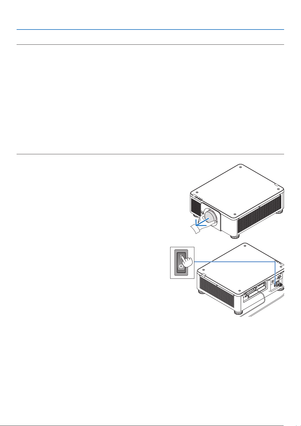
1. Remove the lens cap from the lens unit.
2. Press the main power switch to the ON position ( I ).
POWER indicator lights up in green. If there is no opera-
tion from the unit or communication from the connected
device, the unit will go into the standby state after a while.
(When the standby mode is set to “Normal”)
(→ page 126)
16
Page 32

3. Press the (POWER) button on the projector cabinet
or the POWER ON button on the remote control.
WARNING
The projector produces a strong light. When turning on
the power, make sure no one within projection range is
looking at the lens.
The POWER indicator goes from a steady green light to
a ashing blue light, and the picture is projected on the
screen.
TIP:
• When the message “PROJECTOR IS LOCKED! ENTER YOUR
PASSWORD.” is displayed, it means that the [SECURITY]
feature is turned on. (→ page 46)
After you turn on your projector, ensure that the computer
or video source is turned on.
NOTE:
• The blue screen ([BLUE] background) is displayed when no signal
is being input (by factory default menu settings).
2. Projecting an Image (Basic Operation)
Sleep Blinking Power On
Steady green light
Blinking blue
light
Steady blue
light
Performing Lens Calibration
After installation or replacement of the lens, be sure to perform
[LENS CALIBRATION] by pressing and holding the CALIBRATION button on the projector cabinet for at least two seconds
or by holding the CTL button and pressing the INFO/L-CALIB.
button on the remote control. Perform [LENS CALIBRATION]
also when trouble is found on the lens shift motion. Calibration corrects the adjustable zoom, shift, and focus range. If
calibration is not performed, you may not be able to get the
best focus and zoom even if you adjust the focus and zoom
for the lens. While performing Lens Calibration, the STATUS
indicator ashes in green twice per cycle.
• The following lenses need calibration:
NP16FL-4K, NP17ZL-4K, NP18ZL-4K, NP19ZL-4K,
NP20ZL-4K, NP21ZL-4K, NP31ZL-4K
17
Page 33

2. Projecting an Image (Basic Operation)
Note on Startup screen (Menu Language Select screen)
When you rst turn on the projector, you will get the Startup menu. This menu gives you the opportunity to select one
of the 30 menu languages.
To select a menu language, follow these steps:
1. Use the ▲, ▼, ◀ or ▶ button to select one of the 30
languages from the menu.
2. Press the ENTER button to execute the selection.
After this has been done, you can proceed to the menu
operation.
If you want, you can select the menu language later.
(→ [LANGUAGE] on page 75 and 105)
NOTE:
• If the message, [PLEASE SET "DATE AND TIME".] is shown, please set the current date and time. (→ page 115)
• In the case this message is not shown, the [DATE AND TIME SETTING] is recommended to complete.
• If one of the following things happens, the projector will not turn on.
- If the internal temperature of the projector is too high, the projector detects abnormal high temperature. In this condition the
projector will not turn on to protect the internal system. If this happens, wait for the projector’s internal components to cool
down.
- If the STATUS indicator lights orange with the power button pressed, it means that the [CONTROL PANEL LOCK] is turned on.
Cancel the lock by turning it off. (→ page 115)
• While the POWER indicator is blinking blue in short cycles, the power cannot be turned off by using the power button. (While the
POWER indicator is blinking blue in long cycles, the OFF TIMER is functioned and the power can be turned off.)
18
Page 34

2. Projecting an Image (Basic Operation)
❹ Selecting a Source
Selecting the computer or video source
NOTE:
• Turn on the computer or video source equipment connected to the projector.
Using the Direct button
Press the Direct button on the projector cabinet or remote control.
Select the input according to the connection terminal.
Input connector Button on the projector
cabinet
HDMI1/2 IN HDMI 1/2 HDMI Switches between HDMI1 and HDMI2 each time
DisplayPort 1/2 IN DisplayPort 1/2 DisplayPort
SDI 1/2/3/4 IN SDI AUX • Switches between SDI1, SDI2, SDI3 and SDI4
HDBaseT HDBaseT/SLOT NETWORK Each time the button of the projector cabinet is
SLOT HDBaseT/SLOT SLOT Each time the button of the projector cabinet is
Button on the remote
control
Note
it is pressed.
• Switches between DisplayPort1 and DisplayPort2
each time it is pressed.
• Select DisplayPort1 for dual link.
each time it is pressed.
• Select SDI1 for quad link or dual link.
pressed, the mode switches between HDBaseT
and SLOT.
pressed, the mode switches between HDBaseT
and SLOT.
19
Page 35

2. Projecting an Image (Basic Operation)
Detecting the Signal Automatically
Press the SOURCE button for 1 second or longer. The projector will
search for the available input source and display it. The input source will
change as follows:
HDMI1 → HDMI2 → DisplayPort1 → DisplayPort2 → HDBaseT → SDI1
→ SDI2 → SDI3 → SDI4 → SLOT……
TIP:
• If no input signal is present, the input will be skipped.
• Press it briey to display the [INPUT] screen.
Press the ▼/▲ buttons to match the target input terminal and then
press the ENTER button to switch the input. To delete the menu
display in the [INPUT] screen, press the MENU or EXIT button.
20
Page 36

2. Projecting an Image (Basic Operation)
Selecting Default Source
You can set a source as the default source so that it will be displayed each time the projector is turned on.
1. Press the MENU button.
The menu will be displayed.
2. Press the ▶ button to select [SETUP] and press the ▼ button or the ENTER button to select [MENU(1)].
3. Press the ▶ button to select [SOURCE OPTIONS(1)].
4. Press the ▼ button to select [DEFAULT INPUT SELECT] and press the ENTER button.
The [DEFAULT INPUT SELECT] screen will be displayed.
(→ page 123)
5. Select a source as the default source, and press the ENTER button.
6. Press the EXIT button three times to close the menu.
7. Restart the projector.
The source you selected in step 5 will be projected.
TIP:
• When the projector is in Standby mode, applying a computer signal from a computer will power on the projector and simultaneously project the computer’s image.
([AUTO POWER ON SELECT] → page 126)
21
Page 37
2. Projecting an Image (Basic Operation)
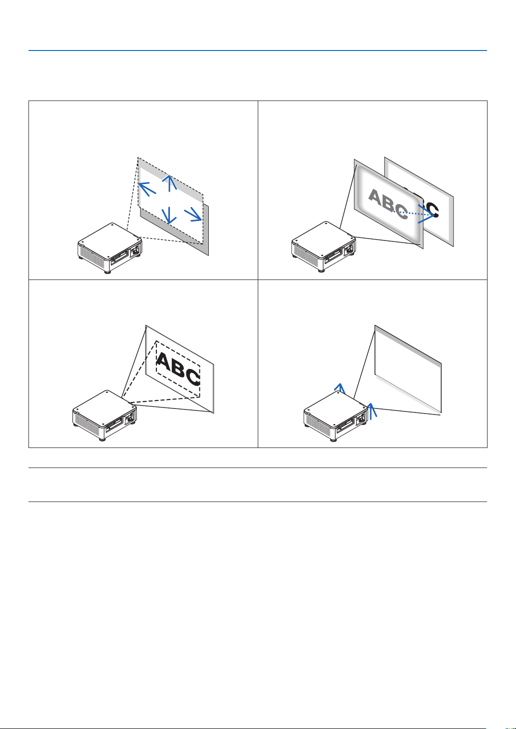
❺ Adjusting the Picture Size and Position
In this chapter drawings and cables are omitted for clarity.
Adjusting the projected image’s vertical and horizontal
position
[Lens shift]
(→ page 23)
Finely adjusting the size of an image
[Zoom]
(→ page 31)
Adjusting the focus
[Focus]
(→ page 26)
Adjusting the projected image’s height and horizontal tilt
[Tilt foot] *¹
(→ page 32)
NOTE*1:
• Adjust the projected image’s height using the tilt foot when you want to project the image at a position higher than the lens shift
adjustment range.
TIP:
• Built-in test patterns can be conveniently used for adjusting the picture size and position. (→ page 79)
A press of the TEST button will display the test pattern. The ◀ or ▶ button can select one test pattern. To close the test pattern,
change the source to another.
22
Page 38
2. Projecting an Image (Basic Operation)
Adjusting the vertical position of a projected image (Lens shift)
CAUTION
• Perform the adjustment from behind or from the side of the projector. Performing adjustment from the front could
expose your eyes to strong light which could injure them.
• Keep hands away from the lens mounting portion while performing a lens shift. Failure to do so could result in
ngers being pinched by the moving lens.
NOTE:
• The lens shift function is not available on the projector with either NP16FL-4K or NP39ML-4K lens installed.
For using NP16FL-4K, set back the lens to the home position.
For using NP39ML-4K, select [SETUP] → [INSTALLATION(2)] → [LENS POSITION] → [TYPE] on the onscreen menu, the lens
will be moved to the appropriate position automatically.
• Shifting the lens to the maximum in oblique angle will cause the edges of the image to become dark or will cause dark shadows.
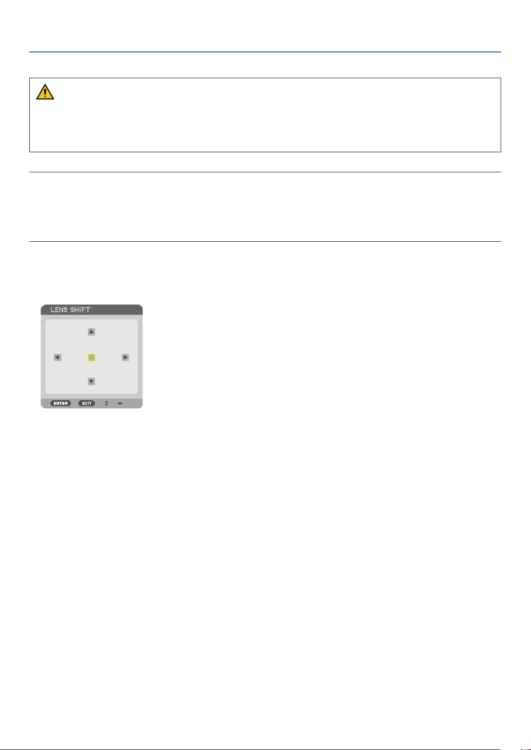
Adjusting with buttons on the cabinet
1. Press the SHIFT/HOME button.
The [LENS SHIFT] screen will be displayed.
23
Page 39

2. Press the ▼▲◀ or ▶ button.
Use the ▼▲◀▶ buttons to move the projected image.
2. Projecting an Image (Basic Operation)
• Returning the lens shift position to the home position
Press and hold the SHIFT/HOME button for 2 seconds to return the lens shift position to the home position
(nearly center position)
24
Page 40

2. Projecting an Image (Basic Operation)
Adjusting with the remote control
1. Hold the CTL button and press the ECO/L-SHIFT button.
The [LENS SHIFT] screen will be displayed.
2. Press the ▼▲◀ or ▶ button.
Use the ▼▲◀▶ buttons to move the projected image.
NOTE:
Lens Calibration
If the power of the projector is wrongly shut down during the motion of lens shift, it may shift the home position of the lens and
may cause of malfunction. The STATUS indicator flashed in Orange to inform this kind of trouble occurrence. In this case, perform
lens calibration.
Lens calibration procedures
1. Power on the projector.
2. Press the (CALIBRATION) button on the control panel over 2 seconds or keep pressing the CTL button and press the INFO/LCALIB. button on the remote control.
Calibration is performed.
TIP:
• The diagram below shows the lens shift adjustment range (projection mode: desktop front). To raise the projection position higher
than this, adjust by the tilt foot. (→ page 32)
10%H
50%V
100%V
30%V
100%H
10%H
20%H
Width of projected image
Height of projected image
20%H
Description of symbols: V indicates vertical (height of the projected image), H indicates horizontal (width of the projected image).
25
Page 41

2. Projecting an Image (Basic Operation)
Focus
Recommend to perform the focus adjustment after leaving the projector under the state the TEST PATTERN has
been projected for over 30 minutes.
Please refer to page 82 in the User’s Manual about the TEST PATTERN.
Applicable lens unit: NP16FL-4K/NP17ZL-4K/NP18ZL-4K/NP19ZL-4K/NP20ZL-4K/NP21ZL-4K
1. Press the FOCUS button.
The FOCUS adjustment bar will be displayed on.
2. Press ◀▶ buttons to adjust focus.
• On the remote control, while pressing on the CTL button, press on VOL/FOCUS (+) or (−) button.
• ◀ or ▶ buttons on the remote control are also available to adjust FOCUS while the FOCUS adjustment bar is
displayed on.
TIP:
• To obtain the best focus, perform the following (for permanent installation)
Preparation: Warm up the projector for one hour.
1. Use the FOCUS button and the ◀▶ buttons to make sure you obtain the best focus. If you do not, move the projector back and
forth.
2. Select the [TEST PATTERN] from the menu and display the test pattern. (→ page 79)
• You can also use the TEST button on the remote control to display the test pattern.
3. Press the FOCUS button to display the focus adjustment bar, then press the ◀ button until the pixel lattice of the test pattern
cannot be seen any more.
• The FOCUS adjustment bar displaying position can be shifted or be turned off temporarily. (→ page 36)
4. Keep pressing the ▶ button until you obtain the best focus.
If you adjust beyond the best focal point, go back to step 3 and repeat the procedures.
26
Page 42

2. Projecting an Image (Basic Operation)
Applicable lens unit: NP31ZL-4K
1. Focus on the projected image around the optical axis. (Powered focus)
Press the FOCUS button to display the focus adjustment bar. Press the ◀▶ button to adjust the focus near the
optical axis.
• On the remote control, while pressing on the CTL button, press on VOL/FOCUS (+) or (−) button.
• ◀ or ▶ buttons on the remote control are also available to adjust FOCUS while the FOCUS adjustment bar is
displayed on.
The drawing below shows an example when the projected image is shifted upward. In this case the optical axis
is at the bottom edge of the projected image.
* When the lens is at the center position, the optical axis is at the
center of the image. In this case, adjust the focus at the center of
the projected image.
Optical axis
27
Page 43

2. Projecting an Image (Basic Operation)
2. Adjust the focus at the edges of the projected image. (Manual focus)
Turn the edge focus ring clockwise or counterclockwise.
Optical axis
This completes adjusting the projected image’s overall focus.
NOTE:
• The NP31ZL-4K supports the Lens Memory function, which allows you to store adjusted value for Lens Shift, Zoom, and Focus.
If you accidentally move the Edge focus ring (drawing shown below) after having stored adjusted values, the adjusted values
stored in the Lens Memory will not be correctly applied.
Edge focus ring
After having removed the lens from the projector and mounted it back, call up the adjusted values stored in the Lens Memory and
then follow Step 2 in the procedure above to adjust the focus at the edges of the projected image again.
28
Page 44

2. Projecting an Image (Basic Operation)
TIP:
• To obtain the best focus, perform the following (for permanent installation)
Preparation: Warm up the projector for one hour.
1. Press the FOCUS button and the ◀▶ buttons to check the adjustable focus range. For checking it by the remote control, press
and hold the CTL button and press VOL./FOCUS +/− button. If the projector in use is not within the adjustable focus range,
move the projector back and forth.
2. Select the [TEST PATTERN] from the menu and display the test pattern. (→ page 79)
• For displaying the test pattern by the remote control, press TEST button.
3. Press the FOCUS button to display the Focus Adjustment Bar, then press the < button until the pixel lattice of the test pattern
cannot be seen any more.
• The FOCUS adjustment bar displaying position can be shifted or be turned off temporarily. (→ page 36)
4. Keep pressing the ▶ button until you obtain the best focus.
For obtaining the best focus by the remote control, press the VOL./FOCUS + button while holding to press the CTL button.
If you adjust beyond the best focal point, go back to step 3 and repeat the procedures.
5. Turn the edge focus ring clockwise or counterclockwise to adjust the focus at the edges of the projected image.
Applicable lens unit: NP39ML-4K
1. Focus on the projected image around the optical axis. (Powered focus)
Press the FOCUS button to display the focus adjustment bar. Press the ◀▶ button to adjust the focus near the
optical axis.
• On the remote control, while pressing on the CTL button, press on VOL/FOCUS (+) or (−) button.
• ◀ or ▶ buttons on the remote control are also available to adjust FOCUS while the FOCUS adjustment bar is
displayed on.
Optical axis
29
Page 45

2. Projecting an Image (Basic Operation)
2. Adjust the focus at the edges of the projected image.
Press the ZOOM button to display the zoom adjustment bar. Press the ◀▶ button to adjust the focus around the
screen.
Focus around the optical axis set at step 1 is remained unchanged.
Optical axis
3. Repeat steps 1 and 2 until the optimal focus can be obtained on whole image.
TIP:
• To obtain the best focus, perform the following (for permanent installation)
Preparation: Warm up the projector for one hour.
1. Use the FOCUS button and the ◀▶ buttons to make sure you obtain the best focus. If you do not, move the projector back and
forth.
2. Select the [TEST PATTERN] from the menu and display the test pattern. (→ page 79)
• You can also use the TEST button on the remote control to display the test pattern.
3. Press the FOCUS button to display the Focus Adjustment Bar, then press the ◀ button until the pixel lattice of the test pattern
cannot be seen any more.
• The FOCUS adjustment bar displaying position can be shifted or be turned off temporarily. (→ page 36)
4. Keep pressing the ▶ button until you obtain the best focus.
If you adjust beyond the best focal point, go back to step 3 and repeat the procedures.
5. Press the ZOOM button to display the zoom adjustment bar and press the ◀▶ button to adjust the focus around the screen.
Press the D-ZOOM/ZOOM +/− button holding to press the CTL button for adjusting it by the remote control.
Repeat steps 1 to 5 until the optimal focus can be obtained on whole image.
30
Page 46

2. Projecting an Image (Basic Operation)
Zoom
Applicable lens units: NP17ZL-4K/NP18ZL-4K/NP19ZL-4K/NP20ZL-4K/NP21ZL-4K/NP31ZL-4K
1. Press the ZOOM button.
The ZOOM adjustment bar will be displayed on.
2. Press ◀▶ buttons to adjust zoom.
• On the remote control, while pressing on the CTL button, press the D-ZOOM/ZOOM (+) or (−) button.
The zoom is adjusted.
• ◀ or ▶ buttons on the remote control are available to adjust ZOOM while the ZOOM adjustment bar is displayed
on.
31
Page 47
2. Projecting an Image (Basic Operation)
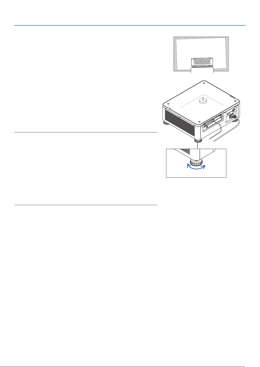
Adjusting the Tilt Foot
1. The position to project image may be adjusted by the tilt foot
positioned at four corners of the cabinet bottom.
The tilt foot height can be adjusted by its turn.
“To adjust the height of the projected image”
The height of the projected image is adjusted by turning either front
or rear tilt foot.
“If the projected image is tilted”
If the projected image is tilted, turn either left or right tilt foot to adjust
the image so that it is level.
• If the projected image is distorted, see “3-8 Correcting Horizontal
and Vertical Keystone Distortion [CORNERSTONE]” (→ page 43)
and “[GEOMETRIC CORRECTION]” (→ page 97).
• The tilt foot can be lengthened by a maximum of 48 mm.
• The tilt foot can be used to tilt the projector by a maximum of 6°.
NOTE:
• Do not lengthen the tilt foot any more than 50 mm/1.9". Doing so will make the
tilt feet’s mount section unstable and could cause the tilt feet to come off the
projector.
• Pay attention to lengthen or shorten two tilt foot at front at the same time. Same
for the rear foot, otherwise, the weight of the projector is loaded on one side
and it may cause of damage to it.
• Do not use the tilt foot for any purpose other than adjusting the projector’s
projection angle.
Handling the tilt foot improperly, such as carrying the projector by grasping the
tilt foot or hooking it onto a wall using the tilt foot, could damage the projector.
• Please check level of the lens unit When the lens unit NP39ML-4K is installed
on since the lens unit may sligtly incline in left or right.
Up Down
Tilt foot
(there is one more in the rear)
32
Page 48

2. Projecting an Image (Basic Operation)
❻ Turning off the Projector
1. Press the (POWER) button on the projector cabinet or
the POWER OFF button on the remote control.
The [POWER OFF / ARE YOU SURE ? / CARBON SAVINGS-
SESSION 0.000[g-CO2]] message will appear.
2. Press one among the ENTER, the (POWER), and the
POWER OFF button.
The light source will be turned off and the power supply will
be cut. The projector will go to sleep state and the POWER
indicator will light in green. If no operation is performed on the
projector and no signal is input to the projector, the projector
will be in standby state. (In the state, the standby mode is
NORMAL.)
• If you do not want to turn off, select [NO] by ◀/▶button and
press ENTER.
3. Make sure the projector is in STANDBY MODE, then turn
off the main power switch (○ OFF)
The POWER indicator will go off and the main power will turn
off.
• While the POWER indicator is blinking blue in short cycles,
the power cannot be turned off.
Power On
Steady blue light
Sleep
Steady green light
CAUTION:
Parts of the projector may temporarily overheat if the projector is turned off with the main power switch or the AC
power supply is disconnected while the projector is in operation or the cooling fan is running. Handle with care.
33
Page 49

2. Projecting an Image (Basic Operation)
NOTE:
• Do not unplug the power cord from the projector or from the power outlet while an image is being projected. Doing so could
deteriorate the projector’s AC IN terminal or the power plug’s contact. To turn off the AC power supply when the projector is
powered on, use the projector’s main power switch, a power strip equipped with a switch, or a breaker.
• Do not turn off the main power switch or disconnect the AC power supply within 10 seconds of making adjustments or setting
changes and closing the menu. Doing so can cause loss of adjustments and settings.
❼ After Use
Preparation: Make sure that the projector is turned off.
1. Unplug the power cord.
2. Disconnect any other cables.
3. Mount the lens cap on the lens.
4. Before moving the projector, screw in the tilt foot if they have been lengthened.
34
Page 50

3. Convenient Features
❶ Turn off the light of the projector (LENS SHUTTER)
Press the SHUTTER button.
The light source will turn off temporarily.
Press again to allow the screen to become illuminated again.
• You can set the projection light to gradually fade in or out.
❷ Turning off the Image (AV-MUTE)
Press the AV-MUTE button to turn off the image for a short period of time.
Press again to restore the image.
TIP:
• The video will disappear but not the menu display.
❸ Turning Off the On-Screen Menu (On-Screen Mute)
A press of the ON-SCREEN button on the remote control will hide the
on-screen menu, the source display and other messages. Press again
to restore them.
TIP:
• To confirm that the on-screen mute is turned on, press the MENU button. If the on-screen menu is not displayed even though
you press the MENU button, it means the on-screen mute is turned on.
• The on-screen mute is maintained even when the projector is turned off,
• Holding down the MENU button on the projector cabinet for at least 10 seconds will turn off the on-screen mute.
35
Page 51

3. Convenient Features
❹ Shift the On-Screen Menu displaying position
1. Press the MENU button.
The On-Screen Menu will be displayed on.
2. Move the cursor by the ▶ button to the [SETUP] and then press the ENTER button.
The cursor will move to the [MENU(1)].
3. Move the cursor by the ▶ button to the [MENU(2)].
4. Move the cursor by the ▼ button to the [MENU POSITION] and then press the ENTER.
The On-Screen Menu will go into the [MENU POSITION] select screen.
5. Press the ▼▲ button, select the menu position, and press the ENTER button.
For nishing the setting on the On-Screen Menu, press the MENU button on the remote control.
TIP:
• The display position of the menu is saved even when the power supply of the projector is turned off.
• When you change the [MENU ANGLE], the display position of the menu returns to the original state when it was first shipped
from the factory.
• This function does not influence to the display position of input terminal information and message.
36
Page 52

❺ Freezing a Picture
Hold the CTL button and press the PIP/FREEZE button to freeze a picture.
Press again to resume motion.
NOTE:
• The image is frozen but the original video is still playing ahead.
3. Convenient Features
37
Page 53

3. Convenient Features
❻ Magnifying a Picture
You can magnify the picture up to four times.
NOTE:
• Depending on an input signal, the maximum magnification may be less than four times, or the function may be restricted.
To do so:
1. Press the D-ZOOM (+) button to magnify the picture.
2. Press the ▲▼◀▶ button.
The area of the magnied image will be moved
3. Press the D-ZOOM (−) button.
Each time the D-ZOOM (−) button is pressed, the image is demagni-
ed.
NOTE:
• The image will be magnified or demagnified at the center of the screen.
• Displaying the menu will cancel the current magnification.
38
Page 54

3. Convenient Features
❼ Adjustment of luminance (brightness) and energy-saving
effect
You can adjust the output of the unit to a range of 20 - 100% (in increments of 1%) and control the brightness after
adjustment to keep it constant. Also, set the [REF. LIGHT MODE] to ECO1 or ECO2 to reduce the brightness and
operating sound. By saving energy consumption, the CO2 emission from this projector can be reduced. There are
two ways to set the light mode.
Function name Description Page
REF. LIGHT
MODE
The adjustment values of the [REF. LIGHT MODE] and brightness are saved as a
setting common to all input signals.
Valid when the [MODE] (→ page 83) is set to [STANDARD].
REF. LIGHT
MODE
NORMAL 100% brightness
ECO1
ECO2
Icon at the
bottom of
the menu
Description
The screen will be brightly lit.
Brightness will be at about 80%.
The cooling fan will also slow down accordingly.
Lower power consumption
Brightness will be at about 50%.
The cooling fan will also slow down accordingly.
Lower power consumption considerably
108
LIGHT MODE Adjust the brightness and save it for each input signal.
Valid when the [MODE] (→ page 83) is set to [PROFESSIONAL].
Display the LIGHT MODE screen
1. Press LIGHT button on the cabinet.
• In another way, press ECO/L-SHIFT button on the remote control.
When [STANDARD] is selected for [MODE]
The [REF. LIGHT MODE] screen will be displayed.
When [PROFESSIONAL] is selected for [MODE]
The [LIGHT MODE] screen will be displayed.
85
39
Page 55

3. Convenient Features
Perform LIGHT ADJUST
An explanation is given here using the [REF. LIGHT MODE] screen.
1. Press the ▼ button to adjust the cursor to [REF. LIGHT ADJUST].
2. Press the ◀▶ button to adjust.
To keep the brightness after adjustment constant, set [CONSTANT BRIGHTNESS] to [ON].
Press the MENU button to cancel the menu screen.
TIP:
• Brightness normally decreases with use, but by selecting [CONSTANT BRIGHTNESS] mode, sensors inside the projector detect
brightness and automatically adjust the output, thereby maintaining a constant brightness throughout the life of the light module.
However, if output is already at its maximum, brightness will decrease with use.
Change [REF. LIGHT MODE]
1. With the cursor adjusted to [REF. LIGHT MODE], press the ENTER button.
The [REF. LIGHT MODE] selection screen will be displayed.
2. Use the ▼▲ buttons to make a selection, and press the ENTER button.
The display will return to the [REF. LIGHT MODE] screen and the selected option will be applied.
Press the MENU button to return to the original screen.
40
Page 56

3. Convenient Features
NOTE:
• The light module hours used can be checked in [USAGE TIME] on the menu. Select [INFO.] → [USAGE TIME].
• After a lapse of 1 minute from when the projector displays a blue, black or logo screen, [REF. LIGHT MODE] will automatically
switch to [ECO].
• This projector equips the sensor to detect atmospheric pressure and temperature and the projector controls the power based on
the detected values. When the projector is used in high altitude and high temperature, the light source brightness becomes lower
regardless of the setting for LIGHT MODE. This is called “Forced ECO MODE”. Please refer the below table for the conditions and
output power in Forced ECO MODE.
Altitudes Atmospheric temperature
5–30°C
(41–86°F)
1600–3000 m
(5500–10000 ft)
600–1600 m
(2000–5500 ft)
0–600 m
(0–2000 ft)
100% 90% 70%
100% 90% 80%
100% 80%
• When the projector is in the Forced ECO MODE, the picture brightness decreases slightly and the TEMP. indicator lights orange.
At the same time the Thermometer symbol [ ] is displayed at the bottom of the menu.
When in the Forced ECO MODE, the light mode does not change even if the LIGHT MODE setting is changed. When the atmospheric
pressure sensor detects height over 600 m, the HIGH symbol [ ] will be displayed at the bottom of the menu.
31–36°C
(87–96°F)
37–40°C
(98–104°F)
41
Page 57

3. Convenient Features
Checking Energy-Saving Effect [CARBON METER]
This feature will show energy-saving effect in terms of CO2 emission reduction (kg) when the projector’s [LIGHT MODE]
is set to either [ECO1] or [ECO2]. This feature is called as [CARBON METER].
There are two messages: [TOTAL CARBON SAVINGS] and [CARBON SAVINGS-SESSION]. The [TOTAL CARBON
SAVINGS] message shows the total amount of CO2 emission reduction from the time of shipment up to now. You can
check the information on [USAGE TIME] from [INFO.] of the menu. (→ page 129)
The [CARBON SAVINGS-SESSION] message shows the amount of CO2 emission reduction between the time of
changing to LIGHT MODE immediately after the time of power-on and the time of power-off. The [CARBON SAVINGSSESSION] message will be displayed in the [POWER OFF/ ARE YOU SURE ?] message at the time of power-off.
TIP:
• The formula shown below is used to calculate the amount of CO2 emission reduction. Amount of CO2 emission reduction = (Power
consumption in [NORMAL] [REF. LIGHT MODE] – Power consumption in current setting) × CO
energy-saving [LIGHT MODE] is selected, or the Lens Shutter is used, there will be a further reduction in CO
conversion factor.* When an
2
emission.
2
* Calculation for amount of CO2 emission reduction is based on an OECD publication “CO2 Emissions from Fuel Combustion,
2008 Edition”.
• The [TOTAL CARBON SAVINGS] is calculated based on savings recorded in 15 minutes intervals.
• This formula will not apply to the power consumption which is not affected by whether [REF. LIGHT MODE] is turned on or off.
42
Page 58

3. Convenient Features
❽ Correcting Horizontal and Vertical Keystone Distortion
[CORNERSTONE]
Use the [CORNERSTONE] feature to correct keystone (trapezoidal) distortion to make the top or bottom and the left
or right side of the screen longer or shorter so that the projected image is rectangular.
1. Project an image so that the screen is smaller than the area of the raster.
The drawing shows the upper right corner.
Projected image
2. Pick up any one of the corners and align the corner of the image with a corner of the screen.
3. Press the 3D REFORM button.
Display the [GEOMETRIC CORRECTION] screen of the on-screen menu.
4. Move the cursor onto [MODE] by ▼ button and press the ENTER.
The mode selection screen will displayed on.
43
Page 59

3. Convenient Features
5. Press the ▼ button to align with the [CORNERSTONE] and then press the ENTER button.
The drawing shows the upper left icon ( ) is selected.
The screen will switch to the [CORNERSTONE] screen.
6. Use the ▲▼◀▶ button to select one icon (▲) which points in the direction you wish to move the projected
image frame.
7. Press the ENTER button.
8. Use the ▲▼◀▶ button to move the projected image frame as shown on the example.
9. Press the ENTER button.
10
. Use the ▲▼◀▶ button to select another icon which points in the direction.
11
. Repeat steps from 7 to 10 to complete the cornerstone adjustment.
12
. On the [CORNERSTONE] screen, select [EXIT] or press the EXIT button on the remote control.
The conrmation screen is displayed.
13
. Press the ◀ or ▶ button to highlight the [OK] and press the ENTER button.
This completes the [CORNERSTONE] correction.
• Returning to the [CORNERSTONE] screen, select [CANCEL] and press the ENTER button.
44
Page 60

3. Convenient Features
NOTE:
• Even if the installation angle is changed when the projector is turned on again, the correction values in the previous time has been
maintained.
• Carry out either one of the following actions to clear the adjustment value of [CORNERSTONE].
• In Step 12, select [RESET] and then press the ENTER button.
• In the state [CORNERSTONE] has been selected for [MODE] in the [GEOMETRIC CORRECTION]:
• Press the 3D REFORM button for 2 or more seconds.
• Run [GEOMETRIC CORRECTION] → [RESET] in the on-screen menu.
• Using CORNERSTONE correction can cause the image to be slightly blurred because the correction is made electronically.
45
Page 61

3. Convenient Features
❾
Preventing the Unauthorized Use of the Projector [SECURITY]
A keyword can be set for your projector using the Menu to avoid operation by an unauthorized user. When a keyword
is set, turning on the projector will display the Keyword input screen. Unless the correct keyword is entered, the projector cannot project an image.
• The [SECURITY] setting cannot be cancelled by using the [RESET] of the menu.
To enable the Security function:
1. Press the MENU button.
The menu will be displayed.
2. Press the ▶ button twice to select [SETUP] and press the ▼ button or the ENTER button to select [MENU(1)].
3. Press the ▶ button to select [CONTROL].
4. Press the ▼ button three times to select [SECURITY] and press the ENTER button.
The OFF/ON menu will be displayed.
5. Press the ▼ button to select [ON] and press the ENTER button.
The [SECURITY KEYWORD] screen will be displayed.
6. Type your keyword in a combination of the four ▲▼◀▶ buttons and press the ENTER button.
NOTE:
• A keyword must be 4 to 10 digits in length.
46
Page 62

3. Convenient Features
The [CONFIRM KEYWORD] screen will be displayed.
NOTE:
• Make a note of your password and store it in a safe place.
7. Type your keyword in the same combination of ▲▼◀▶ buttons and press the ENTER button.
The conrmation screen will be displayed.
8. Select [YES] and press the ENTER button.
The SECURITY function has been enabled.
To turn on the projector when [SECURITY] is enabled:
1. Press the button.
• If using the remote control, press the POWER ON button.
The projector will be turned on and display a message to the effect
that the projector is locked.
2. Press the MENU button.
3. Type in the correct keyword and press the ENTER button. The projector will display an image.
NOTE:
• The security disable mode is maintained until the main power is turned off or unplugging the power cord.
47
Page 63

To disable the SECURITY function:
1. Press the MENU button.
The menu will be displayed.
2. Select [SETUP] → [CONTROL] → [SECURITY] and press the ENTER button.
The OFF/ON menu will be displayed.
3. Select [OFF] and press the ENTER button.
3. Convenient Features
The SECURITY KEYWORD screen will be displayed.
4. Type in your keyword and press the ENTER button.
When the correct keyword is entered, the SECURITY function will be disabled.
NOTE:
• If you forget your keyword, contact your dealer. Your dealer will provide you with your keyword in exchange for your request
code. Your request code is displayed in the Keyword Confirmation screen. In this example [NB52-YGK8-2VD6-K585-JNE6-EYA8]
is a request code.
48
Page 64

3. Convenient Features
❿ Controlling the Projector by Using an HTTP Browser
Overview
Using the web browser on the computer, the HTTP server screen of the projector can be displayed to operate the
projector.
Possible operations on the HTTP server screen
• Congure the settings required for connecting the projector to the network (wired LAN).
• Congure the email notication. (ALERT MAIL)
When the projector is connected to a network (wired LAN), notications on various errors are sent to the email
address that has been set up.
• Operate the projector.
Operations such power on/off of the projector, input terminal switchover, picture control, and lens control etc. can
be carried out.
• Congure the [PJLink PASSWORD], [AMX BEACON], and [CRESTRON] etc.
For details about settings and adjustments, see the explanation on the screen menu.
To view the HTTP server screen
1. Connect the projector to the computer with a LAN cable sold commercially. (→ page 9)
2. Select [SETUP] → [NETWORK SETTINGS] → [WIRED LAN] in the on-screen menu to congure the network
settings. (→ page 119)
3. Start up the web browser on your computer and enter the address or URL in the input eld.
Specify the address or URL as “http://<IP Address of Projector>/index.html”.
The HTTP server screen will be displayed.
TIP:
• The factory setting IP address is [DHCP ON].
NOTE:
• To use the projector in a network, consult with your network administrator about network settings.
• The display’s or button’s response can be slowed down or operation may not be accepted depending the settings of your network.
Should this happen, consult your network administrator. The projector may not respond if its buttons are repeatedly pressed in
rapid intervals. Should this happen, wait a moment and repeat. If you still can’t get any response, turn off and back on the projector.
• If the PROJECTOR NETWORK SETTINGS screen does not appear in the web browser, press the Ctrl+F5 keys to refresh your web
browser (or clear the cache).
• This projector uses “JavaScript” and “Cookies” and the browser should be set to accept these functions. The setting method will
vary depending on the version of browser. Please refer to the help files and the other information provided in your software.
Preparation before Use
Connect the projector to a commercially available LAN cable before engaging in browser operations. (→ page 9)
Operation with a browser that uses a proxy server may not be possible depending on the type of proxy server and the
setting method. Although the type of proxy server will be a factor, it is possible that items that have actually been set
will not be displayed depending on the effectiveness of the cache, and the contents set from the browser may not be
reected in operation. It is recommended that a proxy server not be used unless it is unavoidable.
49
Page 65

3. Convenient Features
Handling of the Address for Operation via a Browser
Regarding the actual address that is entered for the address or entered to the URL column when operation of the
projector is via a browser, the host name can be used as it is when the host name corresponding to the IP address
of the projector has been registered to the domain name server by a network administrator, or the host name corresponding to the IP address of the projector has been set in the “HOSTS” le of the computer being used.
Example 1: When the host name of the projector has been set to “pj.nec.co.jp”, access is gained to the network
setting by specifying
http://pj.nec.co.jp/index.html
for the address or the entry column of the URL.
Example 2: When the IP address of the projector is “192.168.73.1”, access is gained to the network setting by
specifying
http://192.168.73.1/index.html
for the address or the entry column of the URL.
50
Page 66

3. Convenient Features
⓫ Storing Changes for Lens Shift, Zoom, and Focus [LENS
MEMORY]
The adjusted values can be stored in projector memory when using the LENS SHIFT, ZOOM and FOCUS buttons
of the projector. Adjusted values can be applied to the signal you selected. This will eliminate the need to adjust lens
shift, focus, and zoom at the time of source selection. There are two ways to save adjusted values for lens shift,
zoom, and focus.
Function name Description page
REF. LENS MEMORY Adjusted values common to all input signals. At the time of installation,
two kinds of adjusted values can be stored.
If no adjusted values are stored in [LENS MEMORY], adjusted values
from the selected prole ([REF. LENS MEMORY]) will be applied for
lens adjustment.
LENS MEMORY Adjusted values for each input signal.
Use the adjusted values for the signal with a different aspect ratio or
resolution. The adjusted values can be applied at the time of source
selection.
NOTE:
• For using the lens unit NP16FL-4K, NP17ZL-4K, NP18ZL-4K, NP19ZL-4K, NP20ZL-4K, NP21ZL-4K, and NP31ZL-4K, be sure to
carry out [LENS CALIBRATION] after replacing the lens unit. (→ page 17, 110)
• For the lens unit, NP16FL-4K, the storable value as [LENS MEMORY] feature is for [FOCUS] only.
• The [LENS MEMORY] feature is not available for the lens unit, NP39ML-4K.
→ page 110
→ page 93
51
Page 67

To store your adjusted values in [REF. LENS MEMORY]:
1. Press the MENU button.
The menu will be displayed.
2. Press the ▶ button to select [SETUP] and press the ENTER button.
3. Press the ▶ button to select [INSTALLATION(2)].
3. Convenient Features
4. Press the ▼ button to select [REF. LENS MEMORY] and press the ENTER button.
The [REF. LENS MEMORY] screen will be displayed.
52
Page 68

3. Convenient Features
5. Make sure [PROFILE] is highlighted, then press the ENTER button.
The [PROFILE] selection screen appears.
6. Press the ▼/▲ buttons to select the [PROFILE] number, then press the ENTER button.
Return to the [REF. LENS MEMORY] settings screen.
7. Select [STORE] and press the ENTER button.
The conrmation screen will be displayed.
8. Press the ◀ button to select and [YES] and press the ENTER button.
Select a [PROFILE] number and save the adjusted [LENS SHIFT], [ZOOM], and [FOCUS] values to it.
• To turn off the image during the lens shift, set [FORCED MUTE] to [ON]. (→ page 110)
9. Press the MENU button.
The menu will be closed.
TIP:
• To store adjusted values for each input source, use the Lens Memory function. (→ page 93)
53
Page 69

3. Convenient Features
To call up your adjusted values from [REF. LENS MEMORY]:
1. Press the MENU button.
The menu will be displayed.
2. Press the ▶ button to select [SETUP] and press the ENTER button.
3. Press the ▶ button to select [INSTALLATION(2)].
4. Press the ▼ button to select [REF. LENS MEMORY] and press the ENTER button.
The [REF. LENS MEMORY] screen will be displayed.
5. Make sure [PROFILE] is highlighted, then press the ENTER button.
The [PROFILE] selection screen appears.
6. Press the ▼/▲ buttons to select the [PROFILE] number, then press the ENTER button.
Return to the [REF. LENS MEMORY] settings screen.
54
Page 70

7. Select [MOVE] and press the ENTER button.
The lens will shift based on the adjusted values stored in the selected [PROFILE].
8. Press the ◀ button to select and [YES] and press the ENTER button.
The adjusted values will be applied to the current signal. .
9. Press the MENU button.
The menu will be closed.
3. Convenient Features
55
Page 71

3. Convenient Features
TIP:
• To call up the stored values from [LENS MEMORY]:
1. From the menu, select [ADJUST] → [LENS MEMORY] → [MOVE] and press the ENTER button.
The conrmation screen will be displayed.
2. Press the ◀ button to select and [YES] and press the ENTER button.
During projection, if the adjusted values for an input signal have been saved, the lens will shift. If not, the lens
will shift according to the adjusted values stored in the selected [REF. LENS MEMORY] [PROFILE] number.
• To automatically apply the stored values at the time of source selection:
1. From the menu, select [SETUP] → [REF. LENS MEMORY] → [LOAD BY SIGNAL] and press the ENTER
button.
2. Press the ▼ button to select and [ON] and press the ENTER button.
This will move the lens automatically to the position at the time of source selection according to the adjusted
values.
NOTE:
• The Lens Memory function may not produce a completely aligned image (due to tolerances in the lenses) using the adjusted
values stored in the projector. After calling up and applying the stored values from the Lens Memory function, finely adjust the
lens shift, zoom and focus to produce the best possible image.
56
Page 72

4. Multi-Screen Projection
This projector can be used singly or arranged in multiple units for multi-screen projection.
❶ Things that can be done using multi-screen projection
Case 1
Using a single projector to project two or four types of videos at the same time [PICTURE BY PICTURE]
Connection example and projection image
Projecting two types of images
(Input) (Input)
Projecting four types of images
(Input)
(Input)
Case 2
Lien up multiple projectors to project a high-resolution image in a larger screen. [TILING]
Connection example and projection image
(Input)
(Input)
A video splitter
57
Page 73

4. Multi-Screen Projection
❷ Using a single projector to project two or four types of
videos at the same time [PICTURE BY PICTURE]
• The projection video in the rst screen display is known as the MAIN display while the projection video
that is called out subsequently is known as the SUB1, SUB2 and SUB3 display.
MAIN
MAIN SUB1
SUB2
• The PICTURE BY PICTURE function supports the following input terminals and input signals.
Input terminals Two screens SDI1, SDI2, SDI3, SDI4, HDMI1, HDMI2, DisplayPort1, DisplayPort2,
Four screens SDI1, SDI2, SDI3, SDI4, HDMI1, HDMI2, DisplayPort1, DisplayPort2
Input signals Two screens
Four screens Progressive signals up to 1920 × 1080 60 Hz
HDBaseT, SLOT
• When [PORTRAIT ANGLE] is set to [0°],
Signals up to 4K 30 Hz (excluding Deep Color)
• When [PORTRAIT ANGLE] is set to [90°] or [270°],
Progressive signals up to WXGA ++ 60 Hz
1920 × 1080p 24/25/30 Hz signal
SUB1
SUB3
Projecting four screens
This section provides procedures for projecting four types of images at the same time.
Preparation:
Connect the projector to devices that output four types of images and turn on the power of all the devices.
1. Press the MENU button to display the on-screen
menu and select [DISPLAY] → [PICTURE BY PICTURE].
2. Select [MODE] using the ▼/▲ buttons, and press the
ENTER button.
This displays the [MODE] screen.
3. Select [QUAD] using the ▼/▲ buttons, and press the
ENTER button.
The display returns to the PICTURE BY PICTURE
screen.
58
Page 74

4. Multi-Screen Projection
4. Select [SUB1 INPUT] using the ▼/▲ buttons, and
press the ENTER button.
This displays the [SUB1 IMPUT] screen.
5. Select an input signal for SUB 1 using the ▼/▲ but-
tons and press the ENTER button.
The display returns to the PICTURE BY PICTURE
screen.
6. Perform the same steps as 4 and 5 to select input
signals for SUB2 and SUB3.
7. Press the MENU button.
The on-screen menu will disappear.
• To return to a single screen, select [OFF] from the MODE select screen in Step 3.
TIP:
• To project two screens, select [DUAL] in the step 3, and select the input signal for SUB1 in the steps 4 and 5.
• In the case of projecting two screens, you can set the orientation of screen to the portrait position or adjust the display position.
(→ page 95, 96)
Restrictions
• The following operations are enabled only for the main display.
• Visual adjustments
• Video magnication / demagnication using the partial D-ZOOM/ZOOM +/− buttons.
• The following operations are enabled for MAIN, SUB1, SUB2, and SUB3. These operations cannot be applied
individually.
• Momentary deletion of video (AV Mute)
• Video pause (Freeze)
• When TEST PATTERN is displayed, the single screen is projected.
• In the following cases, PICTURE BY PICTURE cannot be used.
• When [PICTURE SETTING] → [MODE] is set to [ZOOM] or [TILING]
• When MAIN is set to SDI1 and [SDI LINK] is set to other than [SINGLE]
• When MAIN is set to DisplayPort 1 and [DP LINK] is set to [DUAL]
• The following operations cannot be made when [PICTURE BY PICTURE] is used.
• DYNAMIC CONTRAST
• IMAGE OPTIONS (when MODE is set to [DUAL] and [PORTRAIT ANGLE] is set to [90°] or [270°])
• ASPECT RATIO (when MODE is set to [QUAD])
59
Page 75

4. Multi-Screen Projection
❸ Line up multiple projectors to display a high resolution
image in a larger screen [TILING]
This section provides procedures for projecting an image with a resolution of 3840 × 2160 (4K UHD) by using four
projectors.
Preparation:
• Arrange four projectors in a 2 × 2 layout.
Connect your video output equipment to the four projectors via a video splitter.
• Turn on the power of all devices to project the same four images
A video splitter
When performing settings or adjustments using one remote control, enable the [CONTROL ID] for assigning ID to each
projector so as not to activate the other projectors. (→ page 116)
60
Page 76

4. Multi-Screen Projection
Things to note when installing projectors
• Leave 30 cm or over space between each projectors and between the intake vent and the wall for installing projectors side by side, so that air intake of the projectors are not obstructed. When the air intake and discharge outlet
are obstructed, the temperature inside the projector will rise and this may result in a malfunction.
30 cm or greater
• Two projectors can be stacked on top of each other (STACK setting). (→ page 139) Do not attempt to directly stack
three or more projectors. When the projectors are piled up on top of one another, they may fall down, resulting in
damage and failure.
• Installation example when using 3 or more projectors
The following installation is recommended when installing a combination of 3 or more projectors for multi-screen
projection.
[Installation example]
Back Back
Air exhaust
Air intake
Exhaust ventIntake vent Cabinet
WARNING
Please request the dealer for special installation services such as when mounting the projector to the ceiling. Never
carry out the installation by yourself. The projector may fall down and result in injury. Please use a sturdy cabinet
that can withstand the weight of the projector for the installation. Please do not pile up the projectors directly on
top of one another.
NOTE:
• For the range of the projection distance, please refer to the Appendix “Throw distance and screen size”. (→ page 143)
61
Page 77

Setting TILING
1. Press the MENU button to display the on-screen
menu and select [DISPLAY] → [PICTURE SETTING]
→ [MODE].
This displays the [MODE] screen.
2. Select [TILING] using the ▼/▲ buttons, and press
the ENTER button.
The display returns to the PICTURE SETTING screen.
3. Select [TILING] using the ▼/▲ buttons, and press
the ENTER button.
This displays the [TILING] screen.
4. Multi-Screen Projection
4. Set [WIDTH], [HEIGHT], [HORIZONTAL POSITION], and [VERTICAL POSITION]
(1) In the screen for setting the number of horizontal units, select [2 UNITS]. (number of units in the horizontal
direction)
(2) In the screen for setting the number of vertical units, select [2 UNITS]. (number of units in the vertical direction)
(3) In the screen for setting the horizontal order, select [1st UNIT] or [2nd UNIT].
(look at the screens, the one on the left is the [1st UNIT] while the one on the right is the [2nd UNIT])
(4) In the screen for setting the vertical order, select the [1st UNIT] or the [2nd UNIT].
(look at the screens, the one at the top is the [1st UNIT] while the one at the bottom is the [2nd UNIT])
62
Page 78

4. Multi-Screen Projection
After completing setting for the steps 1 to 4, a single image will be displayed to ll the screen.
5. Press the MENU button.
The on-screen menu will disappear.
6. Adjust the lens shift of each projector to ne-tune the boundaries of the screen.
To make boundaries less noticeable of a projected image, use [EDGE BLENDING] to adjust them. (→ next page)
63
Page 79

4. Multi-Screen Projection
❹ Adjust boundaries of a projected image [EDGE BLENDING]
This projector is equipped with an “EDGE BLENDING Function” that makes the edges (boundaries) of the projection
screen indistinguishable.
NOTE:
• Before performing the Edge Blending function, place the projector in the correct position so that the image becomes square in
the appropriate size, and then make optical adjustments (lens shift, focus, and zoom).
• Adjust the brightness of each projector using [REF. LIGHT ADJUST] under [REF. LIGHT MODE]. In addition, use [REF. WHITE
BALANCE] to adjust the [CONTRAST], [BRIGHTNESS] and [UNIFORMITY].
The following procedure shows an example of four projectors in a 2 × 2 layout.
Projected area
Projected area
Projected area
Edge Blending area
Projected area
64
Page 80

4. Multi-Screen Projection
Setting the overlap of projection screens
① Enable [EDGE BLENDING].
1. Press the MENU button.
The menu will be displayed.
2. Select [DISPLAY] → [EDGE BLENDING].
The [EDGE BLENDING] screen will be displayed. Align the cursor with [MODE] and then press the ENTER but-
ton. The mode screen will be displayed.
3. Select [MODE] → [ON] and press the ENTER button.
This enables the Edge Blending function. The following menu items are available:
[MARKER], [TOP], [BOTTOM], [LEFT], [RIGHT], [BLEND CURVE], and [BLACK LEVEL]
65
Page 81

4. Multi-Screen Projection
4. Select an appropriate item from [TOP], [BOTTOM], [LEFT], and [RIGHT] for an area of overlapped edges,
and turn on [CONTROL].
TOP: OFF
LEFT: OFF RIGHT: ON
BOTTOM: ON
TOP: ON
LEFT: OFF RIGHT: ON
BOTTOM: OFF
TOP: OFF
LEFT: ON RIGHT: OFF
BOTTOM: ON
TOP: ON
LEFT: ON RIGHT: OFF
BOTTOM: OFF
66
Page 82

4. Multi-Screen Projection
② Adjust [RANGE] and [POSITION] to determine an area of overlapped edges of images
projected from each projector.
Turning on [MARKER] will display markers in magenta and green.
The magenta marker is used for [RANGE] and green one for [POSITION].
[RANGE]
(Determine an area of overlapped edges of images.)
Turn on [RIGHT]
Magenta marker
Magenta marker
Turn on [LEFT]
[POSITION]
(Determine the position of overlapped edges of images.)
Green marker
* The 2 screens are separated in the diagram for explanatory purposes.
67
Page 83
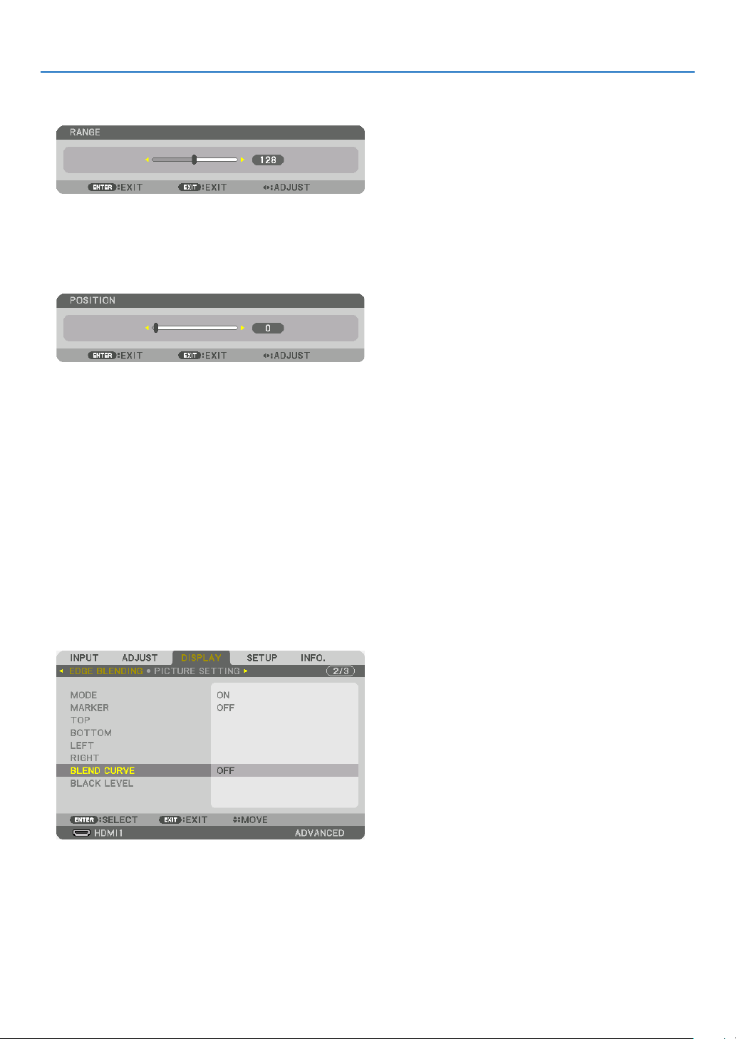
4. Multi-Screen Projection
1 Adjust [RANGE].
Use the ◀ or ▶ button to adjust the overlapped area.
TIP:
• Adjust to overlap one projector’ marker with the other projector’s marker.
2 Adjust [POSITION].
Use the ◀ or ▶ button to align one edge with the other edge of overlapped images.
TIP:
• When displaying a signal with a different resolution, perform the Edge Blending function from the start.
• Setting of [MARKER] will not be saved and return to [OFF] when the projector is turned off.
• To display or hide the marker while the projector is running, turn on or off [MARKER] from the menu.
[BLEND CURVE]
Adjust the brightness of the overlapped section on the screens. According to the necessity, adjust the brightness of
the overlapped section on the screens by the [BLEND CURVE] AND [BLACK LEVEL].
• Set the [MODE] to [ON] for selecting [BLEND CURVE] and [BLACK LEVEL].
Selecting an option for the [BLEND CURVE]
By controlling the graduation of the overlapped section on the screens, it makes the border on the projected screens
inconspicuous. Select the optimal option among nine.
1. On the On-Screen Menu, move the cursor onto the [DISPLAY] → [EDGE BLENDING] → [BLEND CURVE] and
then press the ENTER. The option setting screen for the [BREND CURVE] is displayed on.
68
Page 84

4. Multi-Screen Projection
2. Select one option among nine by ▲ or ▼.
Black Level Adjustment
This adjusts the black level of the overlapping area and the non-overlapping area of the multi-screen (EDGE BLENDING).
Adjust the brightness level if you feel the difference is too large.
NOTE:
• Adjustable area varies depending on what combination of [TOP], [BOTTOM], [LEFT] and [RIGHT] are turned on.
The black level of the lower left projector is adjusted as shown in the gure.
BORDER(TOP)
TOP
BORDER(RIGHT)
CENTER
RIGHT
1. Select [DISPLAY] → [EDGE BLENDING] → [BLACK LEVEL] and press the ENTER button.
The screen will switch to the black level adjustment screen.
69
Page 85

4. Multi-Screen Projection
2. Use the ◀, ▶, ▼ or ▲ button to select an item and use the ◀ or ▶ to adjust the black level.
Do this for the other projector if necessary.
TIP:
9-segmented portions for Black Level adjustment
The black level of the center projector is adjusted as shown in the figure.
BORDER(TOP)
TOP
CENTER
RIGHTLEFT
BORDER(RIGHT)
BOTTOM
BORDER(BOTTOM)BORDER(LEFT)
TIP:
• The number of black level division screens changes depending on the number of edge blending positions selected (top, bottom,
right, left). In addition, when the top / bottom and left / right ends are selected, the corner division screen appears.
• The edge blending width is the width set in the range and the corner is formed by the intersecting area of the top / bottom ends
or left / right ends.
• The [BLACK LEVEL] can be adjusted to make it brighter only.
70
Page 86

5. Using On-Screen Menu
❶ Using the Menus
NOTE:
• The on-screen menu may not be displayed correctly depending on input signal and the projector setting.
1. Press the MENU button on the remote control or the projector cabinet to display the menu.
NOTE:
• The commands such as ENTER, EXIT, ▲▼, ◀▶ in the bottom show available buttons for your operation.
2. Press the ◀▶ buttons on the remote control or the projector cabinet to display the submenu.
3. Press the ENTER button on the remote control or the projector cabinet to highlight the top item or the rst
tab.
4. Use the ▲▼ buttons on the remote control or the projector cabinet to select the item you want to adjust or
set.
You can use the ◀▶ buttons on the remote control or the projector cabinet to select the tab you want.
5. Press the ENTER button on the remote control or the projector cabinet to display the submenu window.
6. Adjust the level or turn the selected item on or off by using the ▲▼◀▶ buttons on the remote control or the
projector cabinet.
Changes are stored until adjusted again.
7. Repeat steps 2-6 to adjust an additional item, or press the EXIT button on the remote control or the projector
cabinet to quit the menu display.
NOTE:
• When a menu or message is displayed, several lines of information may be lost, depending on the signal or settings.
8. Press the MENU button to close the menu.
To return to the previous menu, press the EXIT button.
71
Page 87

❷
Menu Elements
Available buttons
Source
Highlight
Ta b
5. Using On-Screen Menu
Slide bar
Solid triangle
Menu mode
Radio button
REF. LIGHT MODE symbol
High symbol
Thermometer symbol
Key Lock symbol
Menu windows or dialog boxes typically have the following elements:
Highlight ����������������������������� Indicates the selected menu or item�
Solid triangle ����������������������Indicates further choices are available� A highlighted triangle indicates the item is active�
Tab �������������������������������������� Indicates a group of features in a dialog box� Selecting on any tab brings its page to the front�
Radio button ����������������������� Use this round button to select an option in a dialog box�
Source ��������������������������������Indicates the currently selected source�
Menu mode ������������������������Indicates the current menu mode: BASIC or ADVANCED�
Off Timer remaining time ���� Indicates the remaining countdown time when the [OFF TIMER] is preset�
Slide bar �����������������������������Indicates settings or the direction of adjustment�
REF� LIGHT MODE symbol �� Indicates the [REF� LIGHT MODE] is set to [ECO1] or [ECO2]�
Thermometer symbol ���������Indicates the projector is in the Forced ECO MODE�
High symbol �����������������������Indicates the built-in atmospheric pressure sensor detects height over 600 m�
Key Lock symbol ����������������Indicates the [CONTROL PANEL LOCK] is enabled�
Off Timer remaining
time
72
Page 88

5. Using On-Screen Menu
❸ List of Menu Items
• Basic menu items are indicated by shaded area.
Some menu items are not available depending on the input source.
Menu Item Default Options
INPUT
ADJUST
HDMI1
HDMI2
DisplayPort1
DisplayPort2
HDBaseT
SDI1
SDI2
SDI3
SDI4
SLOT
ENTRY LIST
TEST PATTERN
PICTURE
IMAGE
OPTIONS
VIDEO
LENS
MEMORY
MODE STANDARD STANDARD, PROFESSIONAL
PRESET *
GENERAL
REFERENCE *
GAMMA
CORRECTION*
SCREEN SIZE*
COLOR TEMPERATURE*
DYNAMIC CONTRAST * OFF, ON
LIGHT
MODE
Brilliant Color * OFF, MEDIUM, HIGH
DETAIL SETTINGS
CONTRAST 50
BRIGHTNESS 50
SHARPNESS 10
COLOR 50
HUE 0
RESET
HORIZONTAL *
VERTICAL *
BLANKING * TOP, BOTTOM, LEFT, RIGHT
OVERSCAN AUTO AUTO, 0[%], 5[%], 10[%]
ASPECT RATIO
DEINTERLACE NORMAL NORMAL, MOVIE, STILL
CONTRAST
ENHANCEMENT
SIGNAL TYPE AUTO AUTO, RGB, REC601, REC709, REC2020
VIDEO LEVEL AUTO AUTO, NORMAL, ENHANCED, SUPER WHITE
HDR MODE*
STORE
MOVE
RESET
4
WHITE BALANCE
CONTRAST R 0
CONTRAST G 0
CONTRAST B 0
BRIGHTNESS R 0
BRIGHTNESS G 0
BRIGHTNESS B 0
COLOR CORRECTION
RED 0 HUE, SATURATION
GREEN 0 HUE, SATURATION
BLUE 0 HUE, SATURATION
YELLOW 0 HUE, SATURATION
MAGENTA 0 HUE, SATURATION
CYAN 0 HUE, SATURATION
MODE AUTO OFF, AUTO, NORMAL
GAIN
SELECT DYNAMIC, NATURAL, BLACK DETAIL
1
REFERENCE
2
3
LIGHT ADJUST
CONSTANT
BRIGHTNESS
AUTO, HIGH-BRIGHT, PRESENTATION, VIDEO, MOVIE, GRAPHIC,
sRGB, DICOM SIM�, EDGE BLENDING
HIGH-BRIGHT, PRESENTATION, VIDEO, MOVIE, GRAPHIC, sRGB,
DICOM SIM�, EDGE BLENDING
* LARGE, MEDIUM, SMALL
*
OFF OFF, ON
(HDTV/SDTV) AUTO, NORMAL, 4:3, LETTERBOX, WIDE SCREEN,
AUTO
ZOOM, FULL
(COMPUTER) AUTO, NORMAL, 4:3, 5:4, 16:9, 15:9, 16:10, FULL,
AUTO
NATIVE
AUTO AUTO, OFF, ON
* The asterisk (*) indicates that the default setting varies depending on the signal.
*1 The [GAMMA CORRECTION] item is available when an item other than [DICOM SIM.] is selected for [REFERENCE].
*2 The [SCREEN SIZE] item is available when [DICOM SIM.] is selected for [REFERENCE].
*3 When [HIGH-BRIGHT] is selected in [REFERENCE], the [COLOR TEMPERATURE] is not available.
*4 The [HDR MODE] item is available exclusively for 4K signal.
73
Page 89

5. Using On-Screen Menu
Menu Item Default Options
PICTURE BY
PICTURE
GEOMETRIC
CORRECTION
DISPLAY
EDGE
BLENDING
PICTURE
SETTING
MULTI
SCREEN
MODE OFF OFF, DUAL, QUAD
SUB1 INPUT
SUB2 INPUT
SUB3 INPUT
PORTRAIT ANGLE 0° 0°, 90°, 270°
MAIN POSITION
SUB POSITION
MODE
HORIZONTAL
KEYSTONE
CORNERSTONE
HORIZONTAL CORNER
VERTICAL CORNER
WARP
PC TOOL OFF OFF, 1, 2, 3
RESET
MODE OFF OFF, ON
MARKER OFF OFF, ON
TOP
BOTTOM
LEFT
RIGHT
BLEND CURVE 5 OFF, 1, 2, 3, 4, 5, 6, 7, 8, 9
BLACK LEVEL
MODE OFF OFF, ZOOM, TILING
ZOOM
TILING
WHITE BALANCE
VERTICAL
TILT
THROW RATIO
CONTROL ON OFF, ON
RANGE
POSITION
CONTROL ON OFF, ON
RANGE
POSITION
CONTROL ON OFF, ON
RANGE
POSITION
CONTROL ON OFF, ON
RANGE
POSITION
CENTER
TOP
BOTTOM
LEFT
RIGHT
BORDER(TOP)
BORDER(BOTTOM)
BORDER(LEFT)
BORDER(RIGHT)
HORIZONTAL ZOOM
VERTICAL ZOOM
HORIZONTAL POSITION
VERTICAL POSITION
WIDTH
HEIGHT
HORIZONTAL POSITION
VERTICAL POSITION
MODE OFF OFF, ON
CONTRAST W
CONTRAST R
CONTRAST G
CONTRAST B
BRIGHTNESS W
BRIGHTNESS R
BRIGHTNESS G
BRIGHTNESS B
SDI1, SDI2, SDI3, SDI4, HDMI1, HDMI2, DisplayPort1,
DisplayPort2, HDBaseT, SLOT
SDI1, SDI2, SDI3, SDI4, HDMI1, HDMI2, DisplayPort1,
DisplayPort2
SDI1, SDI2, SDI3, SDI4, HDMI1, HDMI2, DisplayPort1,
DisplayPort2
OFF, KEYSTONE, CORNERSTONE, HORIZONTAL CORNER,
VERTICAL CORNER, WARP, PC TOOL
TOP-LEFT, TOP, TOP-RIGHT, LEFT, RIGHT, BOTTOM-LEFT,
BOTTOM, BOTTOM-RIGHT
TOP-LEFT, TOP, TOP-RIGHT, LEFT, RIGHT, BOTTOM-LEFT,
BOTTOM, BOTTOM-RIGHT
TOP-LEFT, TOP, TOP-RIGHT, LEFT, RIGHT, BOTTOM-LEFT,
BOTTOM, BOTTOM-RIGHT
TOP-LEFT, TOP, TOP-RIGHT, LEFT, RIGHT, BOTTOM-LEFT,
BOTTOM, BOTTOM-RIGHT
REFERENCE, RED, GREEN, BLUE, RESET
74
Page 90

5. Using On-Screen Menu
Menu Item Default Options
LANGUAGE ENGLISH
SETUP
MENU(1)
MENU(2)
INSTALLATION(1)
INSTALLATION(2)
COLOR SELECT COLOR COLOR, MONOCHROME
INPUT DISPLAY ON OFF, ON
MESSAGE DISPLAY ON OFF, ON
ID DISPLAY ON OFF, ON
DISPLAY TIME
MENU ANGLE 0° 0°, 90°, 270°
MENU POSITION CENTER
ORIENTATION
SCREEN TYPE FREE FREE, 4:3 SCREEN, 16:9 SCREEN, 16:10 SCREEN
FAN MODE AUTO AUTO, HIGH
REF� LIGHT MODE
REF� WHITE BALANCE
SHUTTER SETTINGS
REF� LENS MEMORY
LENS POSITION
LENS CALIBRATION
REF� LIGHT MODE NORMAL NORMAL, ECO1, ECO2
REF� LIGHT ADJUST
CONSTANT BRIGHTNESS OFF OFF, ON
CONTRAST R
CONTRAST G
CONTRAST B
BRIGHTNESS R
BRIGHTNESS G
BRIGHTNESS B
POWER ON SHUTTER OPEN OPEN, CLOSE
PICTURE MUTE SHUTTER OPEN OPEN, CLOSE
FADE IN TIME 0–10 SEC
FADE OUT TIME 0–10 SEC
PROFILE 1 1, 2
STORE
MOVE
RESET
LOAD BY SIGNAL OFF OFF, ON
FORCED MUTE OFF OFF, ON
HOME
TYPE NP39ML
AUTO 45
DESKTOP
ENGLISH, DEUTSCH, FRANÇAIS, ITALIANO, ESPAÑOL, SVENSKA,
日本語
DANSK, PORTUGUÊS, ČEŠTINA, MAGYAR, POLSKI,
NEDERLANDS, SUOMI
NORSK, TÜRKÇE, РУССКИЙ,
ROMÂNĂ, HRVATSKA, БЪЛГАРСКИ, INDONESIA, , ไทย,
, 繁體中文, Tiếng Việt
MANUAL, AUTO 5 SEC, AUTO 15 SEC, AUTO 45 SEC
SEC
TOP-LEFT, TOP-CENTER, TOP-RIGHT, CENTER-LEFT, CENTER,
CENTER-RIGHT, BOTTOM-LEFT, BOTTOM-CENTER, BOTTOMRIGHT
DESKTOP FRONT, CEILING REAR, DESKTOP REAR, CEILING
FRONT
FRONT
, Ελληνικά, 简体中文, 한국어
75
Page 91

5. Using On-Screen Menu
Menu Item Default Options
ADMINISTRATOR MODE
PROGRAM
TIMER
TOOLS
SETUP CONTROL
DATE AND TIME
SETTINGS
CONTROL PANEL LOCK OFF OFF, ON
SECURITY OFF OFF, ON
COMMUNICATION SPEED 38400bps 4800bps, 9600bps, 19200bps, 38400bps, 115200bps
CONTROL ID
REMOTE SENSOR
MENU MODE ADVANCED ADVANCED, BASIC
NOT SAVE SETTING VALUES OFF OFF, ON
NEW PASSWORD
CONFIRM PASSWORD
ENABLE OFF OFF, ON
SETTINGS
TIME
ZONE
SETTIMGS
DATE
AND TIME
SETTINGS
SUMMER
TIME
SETTINGS
CONTROL ID NUMBER 1 1–254
CONTROL ID OFF OFF, ON
ACTIVE OFF OFF, ON
DAY SUN
TIME
FUNCTION POWER POWER, INPUT
EDIT
ADVANCED
SETTINGS
POWER OFF OFF, ON
INPUT HDMI1
REPEAT OFF OFF, ON
DELETE
UP
DOWN
BACK
UTC
DATE MM/DD/YYYY
TIME HH:MM
INTERNET TIME
SERVER
IP ADDRESS
UPDATE
ENABLE OFF, ON
MON(START) 1, 2, 3, 4, 5, 6, 7, 8, 9, 10, 11, 12
DAY(START)
TIME(START)
MON(EXIT) 1, 2, 3, 4, 5, 6, 7, 8, 9, 10, 11, 12
DAY(EXIT)
TIME(EXIT)
TIME DIFFERENCE +01:00, +00:30, -00:30, -01:00
SUN, MON, TUE, WED, THU, FRI, SAT, MON-FRI, MON-SAT,
EVERY DAY
HDMI1, HDMI2, DisplayPort1, DisplayPort2, HDBaseT, SDI1, SDI2,
SDI3, SDI4, SLOT
-12:00, -11:30, -11:00, -10:30, -10:00, -09:30, -09:00, -08:30,
-08:00, -07:30, -07:00, -06:30, -06:00, -05:30, -05:00, -04:30,
-04:00, -03:30, -03:00, -02:30, -02:00, -01:30, -01:00, -00:30,
00:00, +00:30, +01:00, +01:30, +02:00, +02:30, +03:00, +03:30,
+04:00, +04:30, +05:00, +05:30, +06:00, +06:30, +07:00, +07:30,
+08:00, +08:30, +09:00, +09:30, +10:00, +10:30, +11:00, +11:30,
+12:00, +12:30, +13:00
OFF, ON
FIRST WEEK, SECOND WEEK, THIRD WEEK, FOURTH WEEK, LAST
WEEK
SUN, MON, TUE, WED, THU, FRI, SAT
FIRST WEEK, SECOND WEEK, THIRD WEEK, FOURTH WEEK, LAST
WEEK
SUN, MON, TUE, WED, THU, FRI, SAT
FRONT/
FRONT/BACK, FRONT, BACK, HDBaseT
BACK
76
Page 92

5. Using On-Screen Menu
Menu Item Default Options
WIRED LAN
PROJECTOR NAME PROJECTOR NAME PJ-********
DOMAIN
SETUP
NETWORK
SETTINGS
SOURCE
OPTIONS(1)
SOURCE
OPTIONS(2)
POWER
OPTIONS
RESET
ALERT MAIL
NETWORK SERVICE
DEFAULT INPUT SELECT LAST
BACKGROUND BLUE BLUE, BLACK, LOGO
EDID VERSION
HDCP VERSION
SDI LINK SINGLE SINGLE, QUAD, QUAD(2SI), DUAL
DP LINK SINGLE SINGLE, DUAL
STANDBY MODE NORMAL NORMAL, SLEEP
DIRECT POWER ON OFF OFF, ON
AUTO POWER ON SELECT OFF
AUTO POWER OFF OFF OFF, 0:05, 0:10, 0:15, 0:20, 0:30, 1:00
OFF TIMER OFF OFF, 0:30, 1:00, 2:00, 4:00, 8:00, 12:00, 16:00
SLOT POWER
CURRENT SIGNAL
ALL DATA
ALL DATA (INCLUDING ENTRY LIST)
INTERFACE LAN, HDBaseT
PROFILES PROFILE 1, PROFILE 2
DHCP OFF, ON
IP ADDRESS
SUBNET MASK
GATEWAY
AUTO DNS OFF, ON
DNS CONFIGURATION
RECONNECT
HOST NAME pj-********
DOMAIN NAME
ALERT MAIL OFF, ON
HOST NAME pj-********
DOMAIN NAME
SENDER'S ADDRESS
SMTP SERVER NAME
RECIPIENT'S ADDRESS 1
RECIPIENT'S ADDRESS 2
RECIPIENT'S ADDRESS 3
TEST MAIL
HTTP
SERVER
PJLink
CRESTRON
AMX BEACON OFF, ON
Extron XTP OFF, ON
HDMI1 MODE2 MODE1, MODE2
HDMI2 MODE2 MODE1, MODE2
HDMI1
HDMI2 HDCP2�2 HDCP2�2, HDCP1�4
HDBaseT HDCP1�4 HDCP2�2, HDCP1�4
PROJECTOR ON ON OFF, ON
PROJECTOR STANDBY ENABLE DISABLE, ENABLE
NEW PASSWORD
CONFIRM PASSWORD
NEW PASSWORD
CONFIRM PASSWORD
CLASS CLASS1, CLASS2
DESTINATION
ROOMVIEW OFF, ON
CRESTRON
CONTROL (ENABLE,
CONTROLLER IP
ADDRESS, IP ID)
LAST, AUTO, HDMI1, HDMI2, DisplayPort1, DisplayPort2,
HDBaseT, SDI1, SDI2, SDI3, SDI4, SLOT
HDCP2�2 HDCP2�2, HDCP1�4
OFF, HDMI1, HDMI2, DisplayPort1, DisplayPort2, HDBaseT, SDI1,
SDI2, SDI3, SDI4, SLOT
77
Page 93

5. Using On-Screen Menu
Menu Item Default Options
USAGE TIME
SOURCE(1)
SOURCE(2)
INFO�
WIRED LAN
VERSION
OTHERS
HDBaseT
LIGHT HOURS USED
TOTAL CARBON SAVINGS
INPUT TERMINAL
RESOLUTION
HORIZONTAL FREQUENCY
VERTICAL FREQUENCY
SYNC POLARITY
SCAN TYPE
SOURCE NAME
ENTRY NO�
SIGNAL TYPE
BIT DEPTH
VIDEO LEVEL
IP ADDRESS
SUBNET MASK
GATEWAY
MAC ADDRESS
DNS
FIRMWARE
DATA
FIRMWARE2
DATE TIME
PROJECTOR NAME
MODEL NO�
SERIAL NUMBER
CONTROL ID*
SIGNAL QUALITY
OPERATION MODE
LINK STATUS
HDMI STATUS
5
*5 [CONTROL ID] will be displayed when [CONTROL ID] has been set up.
78
Page 94

❹ Menu Descriptions & Functions [INPUT]
HDMI1
This projects the video of the device connected to the HDMI 1 IN terminal.
HDMI2
This projects the video of the device connected to the HDMI 2 IN terminal.
DisplayPort1
This projects the video of the device connected to the DisplayPort1 IN terminal.
Select this port also when DisplayPort is connected in the dual link mode.
5. Using On-Screen Menu
DisplayPort2
This projects the video of the device connected to the DisplayPort2 IN terminal.
HDBaseT
Projecting the HDBaseT signal.
SDI1
This projects the video of the device connected to the SDI1 IN terminal.
Select this port also when SDI is connected in the quad link or dual link mode.
SDI2
This projects the video of the device connected to the SDI2 IN terminal.
SDI3
This projects the video of the device connected to the SDI3 IN terminal.
SDI4
This projects the video of the device connected to the SDI4 IN terminal.
SLOT
Projects the picture via the optional board (sold separately) inserted into the SLOT.
ENTRY LIST
Displays a list of signals. See the following pages.
TEST PATTERN
Closes the menu and switches to the test pattern screen.
Select the pattern using the ◀▶ buttons.
79
Page 95

5. Using On-Screen Menu
Using the Entry List
The projected signals can be registered in the Entry list. Also, when you perform image settings, lens memory registration, etc., the adjustment value of the signal is automatically registered in the Entry list of this unit. The (adjustment
values of) registered signals can be loaded from the Entry List whenever necessary. When recalling a registered
signal, the video can be displayed faster compared to an unregistered signal.
However, only up to 100 patterns can be registered in the Entry List. When 100 patterns have been registered in the
Entry List, an error message is then displayed and no additional patterns can be registered. You should thus delete
(adjustment values of) signals that are no longer needed.
Displaying the Entry list
1. Press the MENU button.
The menu will be displayed.
2. Press the ◀ or ▶ button to select [INPUT].
The INPUT list will be displayed.
3. Use the ◀, ▶, ▲, or ▼ to select [ENTRY LIST] and press the ENTER button.
The ENTRY LIST windows will be displayed.
If the ENTRY LIST window is not displayed, switch the menu to [ADVANCED].
To switch the menu between [ADVANCED] and [BASIC], select [SETUP] → [CONTROL] → [TOOLS] → [AD-
MINISTRATOR MODE] → [MENU MODE]. (→ page 111)
80
Page 96

5. Using On-Screen Menu
Entering the currently projected signal into the Entry List [ (STORE)]
1. Press the ▲ or ▼ button to select any number.
2. Press the ◀ or ▶ button to select [ (STORE)] and press the ENTER button.
Calling up a signal from the Entry List [ (LOAD)]
Press the ▲ or ▼ button to select a signal and press the ENTER button.
Editing a signal from the Entry List [
1. Press the ▲ or ▼ button to select a signal you wish to edit.
2. Press the ◀, ▶, ▲, or ▼ button to select [ (EDIT)] and press the ENTER button.
The EDIT window will be displayed.
SOURCE NAME Enter a signal name. Up to 18 alphanumeric characters can be used.
INPUT The input terminal can be changed.
LOCK
SKIP
3. Set the above items and select [OK] and press the ENTER button.
NOTE:
• The input terminal cannot be changed to the currently projected signal.
Set so that the selected signal cannot be deleted when [
The changes made after LOCK execution cannot be saved.
Set so that the selected signal will be skipped during auto search.
(EDIT)]
(ALL DELETE)] is executed.
81
Page 97

5. Using On-Screen Menu
Cutting a signal from the Entry List [ (CUT)]
1. Press the ▲ or ▼ button to select a signal you wish to delete.
2. Press the ◀, ▶, ▲, or ▼ button to select [ (CUT)] and press the ENTER button.
The signal will be deleted from the Entry List and the deleted signal will be displayed on the clipboard at the bot-
tom of the Entry List.
NOTE:
• The currently projected signal cannot be deleted.
• When the locked signal is selected, it will be displayed in gray which indicates it is not available.
TIP:
• Data on the clipboard can be passed onto the Entry List.
• Data on the clipboard will not be lost after the Entry List is closed.
Copying and pasting a signal from the Entry List [ (COPY)] / [ (PASTE)]
1. Press the ▲ or ▼ button to select a signal you wish to copy.
2. Press the ◀, ▶, ▲, or ▼ button to select [ (COPY)] and press the ENTER button.
The copied signal will be displayed on the clipboard at the bottom of the Entry List.
3. Press the ◀ or ▶ button to move to the list.
4. Press the ▲ or ▼ button to select a signal.
5. Press the ◀, ▶, ▲, or ▼ button to select [ (PASTE)] and press the ENTER button.
Data on the clipboard will be pasted to the signal.
Deleting all the signals from the Entry List [ (ALL DELTE)]
1. Press the ◀, ▶, ▲, or ▼ button to select [ (ALL DELETE)] and press the ENTER button.
The conrmation message will be displayed.
2. Press the ◀ or ▶ button to select [YES] and press the ENTER button.
NOTE:
• The locked signal cannot be deleted.
Using Test Pattern [TEST PATTERN]
Displays the test pattern for adjusting distortion on the screen and the focus at the time of the projector setup. Once
the [TEST PATTERN] on the onscreen menu is selected, the pattern for adjustment will be displayed on. If you nd
distortion on the pattern, adjust the projector installation angle or correct distortion by pressing the Geometric. button
on the remote. If the focus adjustment is required, press the FOCUS button on the remote control for displaying the
FOCUS adjustment screen and then adjust FOCUS by ◀ or ▶ button. Recommend to perform the focus adjustment
after leaving the projector under the state the TEST PATTERN has been projected for over 30 minutes. Press EXIT
button to close the test pattern and return to the menu.
82
Page 98

5. Using On-Screen Menu
❺ Menu Descriptions & Functions [ADJUST]
[PICTURE]
[MODE]
This function allows you to determine how to save settings for [DETAIL SETTINGS] of [PRESET] for each input.
STANDARD ������������ Saves settings for each item of [PRESET] (Preset 1 through 8)
PROFESSIONAL
NOTE:
• When [TEST PATTERN] is displayed, [MODE] cannot be selected.
����� Saves all the settings of [PICTURE] for each input�
[PRESET]
This function allows you to select optimized settings for your projected image.
You can adjust neutral tint for yellow, cyan or magenta.
There are seven factory presets optimized for various types of images. You can also use [DETAIL SETTINGS] to set
user adjustable settings to customize each gamma or color.
Your settings can be stored in [PRESET 1] to [PRESET 8].
AUTO
��������������������� Automatically distinguish the optimal setting for the input signal�
HIGH-BRIGHT �������� Recommended for use in a brightly lit room�
PRESENTATION ����� Recommended for making a presentation using a PowerPoint file�
VIDEO �������������������� Recommended for typical TV program viewing�
MOVIE ������������������� Recommended for movies�
GRAPHIC ��������������� Recommended for graphics�
sRGB ��������������������� Standard color values
DICOM SIM� ���������� Recommended for DICOM simulation format�
EDGE BLENDING ��� Recommended for edge blending�
NOTE:
• The [DICOM SIM.] option is for training/reference only and should not be used for actual diagnosis.
• DICOM stands for Digital Imaging and Communications in Medicine. It is a standard developed by the American College of Radiology (ACR) and the National Electrical Manufacturers Association (NEMA).
The standard specifies how digital image data can be moved from system to system.
83
Page 99

5. Using On-Screen Menu
[DETAIL SETTINGS]
[GENERAL]
Storing Your Customized Settings [REFERENCE]
This function allows you to store your customized settings in [PRESET 1] to [PRESET 8].
First, select a base preset mode from [REFERENCE], then set [GAMMA CORRECTION] and [COLOR TEMPERATURE].
HIGH-BRIGHT �������� Recommended for use in a brightly lit room�
PRESENTATION ����� Recommended for making a presentation using a PowerPoint file�
VIDEO �������������������� Recommended for typical TV program viewing�
MOVIE ������������������� Recommended for movies�
GRAPHIC ��������������� Recommended for graphics�
sRGB ��������������������� Standard color values�
DICOM SIM� ���������� Recommended for DICOM simulation format�
EDGE BLENDING ��� Recommended for edge blending�
Selecting Gamma Correction Mode [GAMMA CORRECTION]
Each mode in [SELECT] corrects color tone of projected image and is recommended for:
DYNAMIC
NATURAL ���������������Natural reproduction of the picture�
BLACK DETAIL �������Emphasizes detail in dark areas of the picture�
In [REFERENCE], it adjusts corrected value for projected image. Higher value means deeper correction.
NOTE:
• This function is not available when [DICOM SIM.] is selected for [DETAIL SETTINGS].
�������������� Creates a high-contrast picture�
84
Page 100

5. Using On-Screen Menu
Selecting Screen Size for DICOM SIM [SCREEN SIZE]
This function will perform gamma correction appropriate for the screen size.
LARGE
������������������� For screen size of 300"
MEDIUM
SMALL
���������������� For screen size of 200"
������������������� For screen size of 100"
NOTE:
• This function is available only when [DICOM SIM.] is selected for [DETAIL SETTINGS].
Adjusting Color Temperature [COLOR TEMPERATURE]
This option allows you to select the color temperature of your choice.
A value from 5000K to 10500K can be set.
NOTE:
• When [HIGH-BRIGHT] is selected in [REFERENCE], this function is not available.
• When [PRESENTATION] is selected for [REFERENCE], the COLOR TEMPERATURE adjustment changes to 3 levels: 0, 1 and 2.
Adjusting Brightness and Contrast [DYNAMIC CONTRAST]
If [ON] is selected, the most optimal contrast ratio is used according to the picture.
NOTE:
• Depending on the conditions, projector settings such as [DYNAMIC CONTRAST] may not be able to be selected.
Adjusting Brightness [LIGHT MODE]
Adjust the brightness of the projector and save it for each input signal. (→ page 39)
With the [REF. LIGHT MODE] set to [NORMAL], the adjustment will be valid if the PICTURE [MODE] is set to [PROFESSIONAL].
LIGHT ADJUST Brightness can be adjusted in 1% increments from 20 to 100%.
CONSTANT BRIGHTNESS OFF [CONSTANT BRIGHTNESS] mode will be canceled.
ON Maintains the brightness that is in effect at the time [ON] is selected. Unless [OFF]
is selected, the same settings will remain in effect even when the projector is
turned off.
• To re-adjust the brightness, rst turn this setting OFF before making further adjustments.
NOTE:
• [CONSTANT BRIGHTNESS] mode is a function used to maintain the brightness at
a constant level. Color will not be fixed.
• The [CONSTANT BRIGHTNESS] setting will not be saved for each input signal.
[Brilliant Color]
Selects the brightness of the color white.
Selecting options from [MEDIUM] to [HIGH] increases the brightness of the color white.
NOTE:
• If under [REFERENCE], [HIGH-BRIGHT] or [PRESENTATION] are selected, [BrilliantColor] cannot be changed.
85
 Loading...