

NEC NP610 - XGA LCD Projector, NP610 Installation Manual
NEC Display Solutions of America, Inc.
NP610 Installation Guide
Ceiling Mounted and Desktop Rev 1.2
Contents
Product Description, Lens Specs, Notes and Formulas Pg 1
Diagrams & Distance Charts
Cabinet Dimensions
Ceiling Mount Dimensions
Input Panel and Control Codes
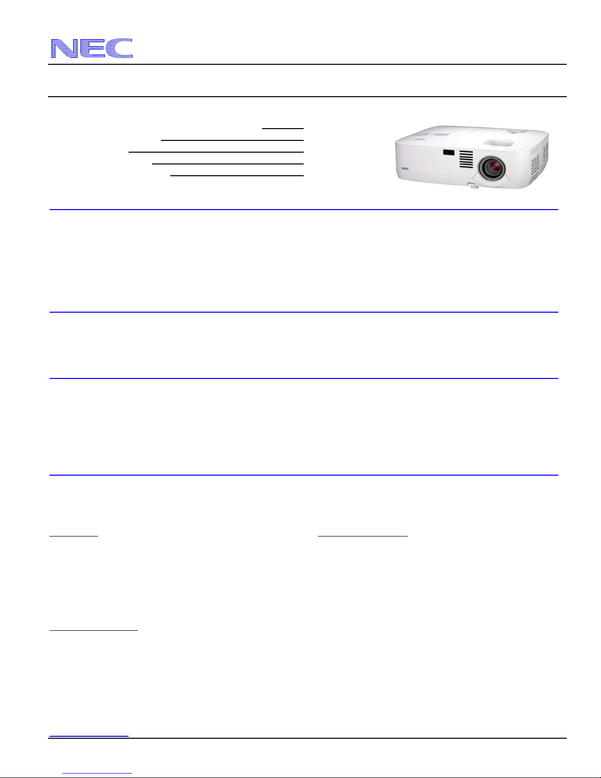
Product Description
Type: 3 panel LCD projector, Dimensions: 12.1” (W) x 4.3” (H) x 10.4” (D)
0.63” p-Si TFT w/MLA Weight: 6.6 lbs
Resolution: 1024 x 768 Brightness: NP610 - 3500 Lumens
Fan Noise: 35 dB / 29dB @ 1 meter
Power Consumption: 312W (max) BTU’s: 1065 BTU/hour
Lens Specifications
Throw Ratio: 1.5 – 1.8:1 (for 100” diagonal) Focal Length: 19.8mm – 23.7mm
Offset Angle: 8.0° - 9.6° (for 100” diagonal) F/#: 1.7 - 2.0
Screen Sizes: 21” - 300” diagonal (4:3) Manual Focus/Manual Zoom
Notes
For screen sizes not indicated on the projection tables, use the formulas below.
If the figures on the tables do not match the results of formulas, use the figures in the table.
All calculations are based on a 4:3 aspect ratio.
Distances are in inches, for millimeters multiply by 25.4.
Distances may vary 5%.
Formulas
The Projection Formulas use the image width for calculation. For proper projection placement, determine the image width
for the desired screen size. Use the Screen Formulas below to calculate all screen dimensions. Plug in the width for “W” in
the Projection Formulas.
Refer to the diagrams and charts for popular screen sizes on page 2:
Definitions: 4:3 Screen Formulas:
W = Image Width W = H x 4/3
H = Image Height (size) H = W x 3/4
B = Vertical distance between lens center and screen center Screen Diagonal = W x 5/4
C = Throw distance
D = Vertical distance between lens center and screen top
(screen bottom for desktop application)
Projection Formulas:
B = 0.258W
C (wide) = 1.539W – 1.176
C (tele) = 1.852W – 1.173
D = -0.118W
α (wide) = tan¯¹ (B/C(wide))
α (tele) = tan¯¹ (B/C(tele))
www.necdisplay.com NP610 Page 1 of 6
Pg 2
Pg 3-4
Pg 5
Pg 6
NEC Display Solutions of America, Inc.
NP610 Installation Guide
Ceiling Mounted and Desktop Rev 1.2
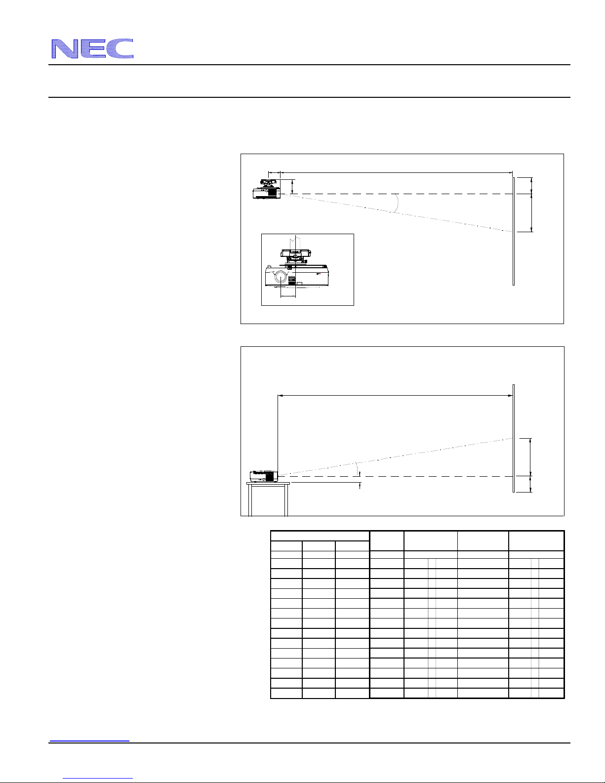
Diagrams and Distance Charts
The following shows the proper relative positions of the projector and screen. Refer to the table to determine the position of
installation.
Distances are in inches. For millimeters multiply by 25.4.
Ceiling Mounted
Desktop
Distance Chart for po
pular 4:3 screens
Note: For screen sizes not indicated on the projection
tables, use the formulas on page 1.
4.56"
5.17"
Lens Offset From
Mount Pipe
2.79
2.22"
Scr een Siz e (4:3)
Diagonal Width(W) Height (H)
inches inches inches inches
30 24 18 6 36 - 43 9.9 - 8.2
60 48 36 12 73 - 88 9.7 - 8.0
67 53.6 40.2 14 81 - 98 9.7 - 8.0
72 57.6 43.2 15 87 - 105 9.6 - 8.0
84 67.2 50.4 17 102 - 123 9.6 - 8.0
90 72 54 19 110 - 132 9.6 - 8.0
100 80 60 21 122 - 147 9.6 - 8.0
120 96 72 25 147 - 176 9.6 - 8.0
150 120 90 31 184 - 221 9.5 - 8.0
180 144 108 37 220 - 265 9.5 - 8.0
210 168 126 43 257 - 310 9.5 - 7.9
240 192 144 50 294 - 354 9.5 - 7.9
270 216 162 56 331 - 398 9.5 - 7.9
300 240 180 62 368 - 443 9.5 - 7.9
C
Throw Distance
C
Throw Distance
B
w ide - tele
C
inc hes
D
inches
-3
-6
-6
-7
-8
-8
-9
-11
-14
-17
-20
-23
-25
-28
Screen Top
D
Lens Ctr
B
Screen Ctr
Screen Ctr
B
Lens Ctr
D
Screen Bottom
α
w ide - tele
degrees
www.necdisplay.com NP610 Page 2 of 6
 Loading...