

NEC NEFAX 671, NEFAX 691 Service Manual

SERVICE MANUAL
FIELD SERVICE
NEC Unified Solutions, Inc.
NEFAX 671/691
SAFETY AND IMPORTANT WARNING ITEMS
Read carefully the Safety and Important Warning Items described below to understand
them before doing service work.
IMPORTANT NOTICE
Because of possible hazards to an inexperienced person servicing this product as well as
the risk of damage to the product, NEC Unified Solutions, INC. (hereafter called the NEC )
strongly recommends that all servicing be performed only by NEC-trained service technicians.
Changes may have been made to this product to improve its performance after this Service
Manual was printed. Accordingly, NEC does not warrant, either explicitly or implicitly, that
the information contained in this Service Manual is complete and accurate.
The user of this Service Manual must assume all risks of personal injury and/or damage to
the product while servicing the product for which this Service Manual is intended.
Therefore, this Service Manual must be carefully read before doing service work both in the
course of technical training and even after that, for performing maintenance and control of
the product properly.
Keep this Service Manual also for future service.
DESCRIPTION ITEMS FOR DANGER,
WARNING AND CAUTION
In this Service Manual, each of three expressions “ DANGER”, “ WARNING”, and
“ CAUTION” is defined as follows together with a symbol mark to be used in a limited
meaning.
When servicing the product, the relevant works (disassembling, reassembling, adjustment,
repair, maintenance, etc.) need to be conducted with utmost care.
DANGER : Action having a high possibility of suffering death or serious injury
WARNING : Action having a possibility of suffering death or serious injury
CAUTION : Action having a possibility of suffering a slight wound, medium
trouble, and property damage
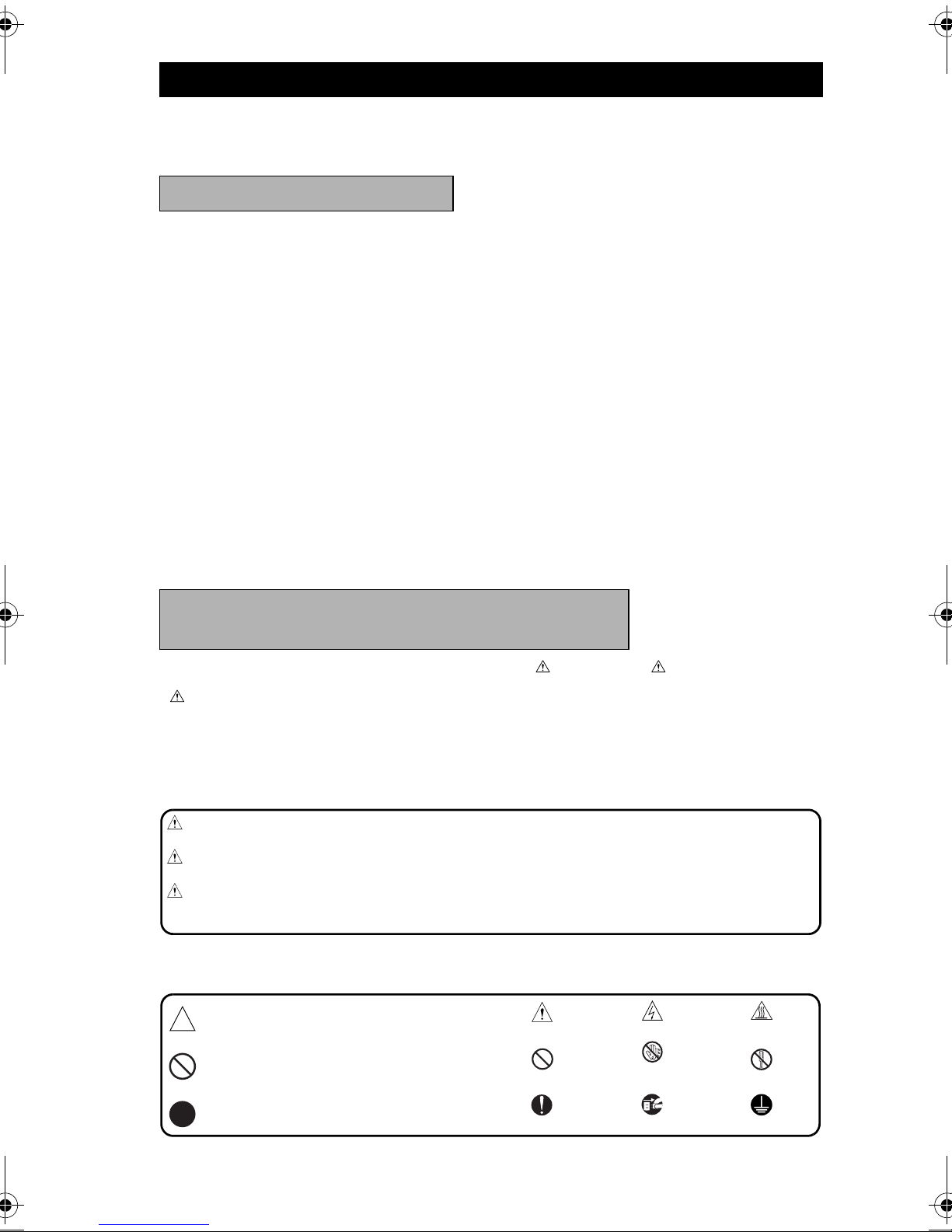
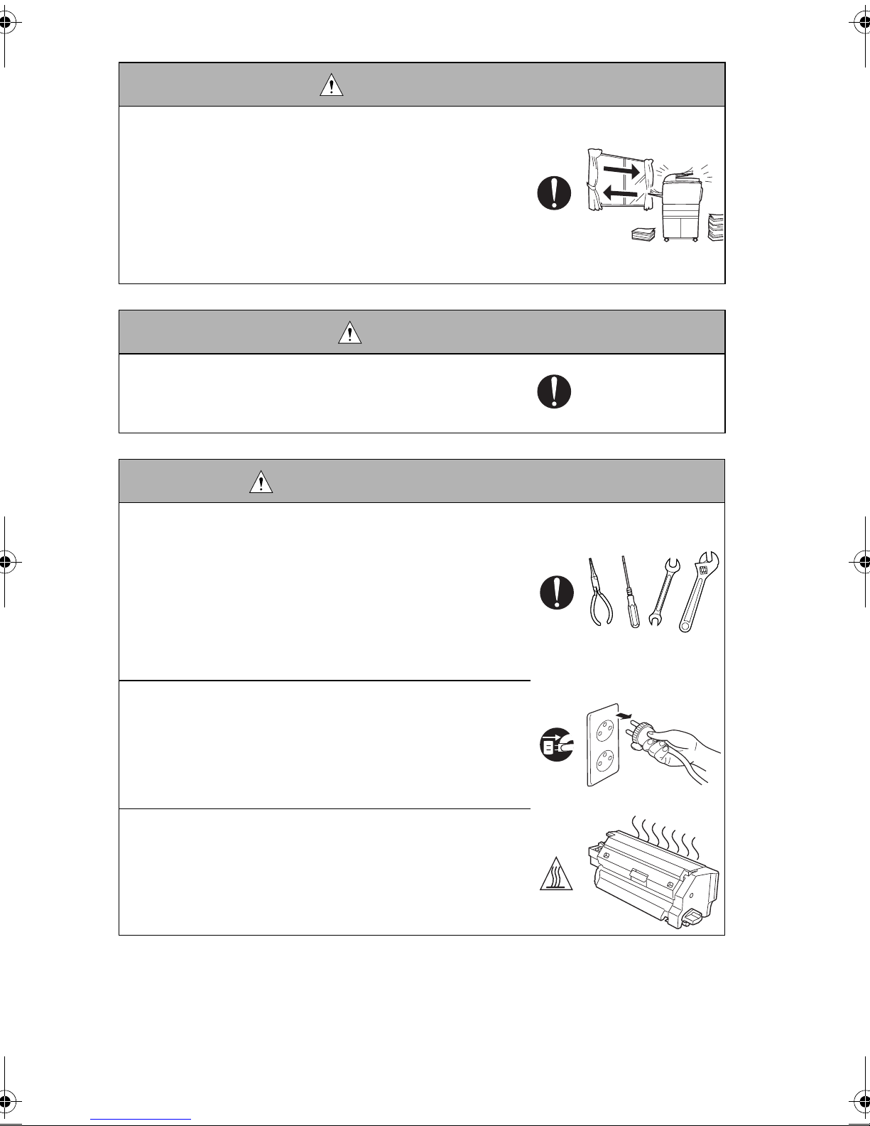
Symbols used for safety and important warning items are defined as follows:
:Precaution when servicing the product.
:Prohibition when servicing the product.
:Direction when servicing the product.
General precaution
General prohibition
General instruction Unplug Ground/ Earth
Electric hazard
Do not touch
with wet hand
High temperature
Do not disassemble
P-1
SAFETY WARNINGS
1. MODIFICATIONS NOT AUTHORIZED BY
NEC UNIFIED SOLUTIONS, INC.
NEC brand products are renowned for their high reliability. This reliability is achieved
through high-quality design and a solid service network.
Product design is a highly complicated and delicate process where numerous mechanical,
physical, and electrical aspects have to be taken into consideration, with the aim of arriving
at proper tolerances and safety factors. For this reason, unauthorized modifications involve
a high risk of degradation in performance and safety. Such modifications are therefore
strictly prohibited. the points listed below are not exhaustive, but they illustrate the reasoning behind this policy.
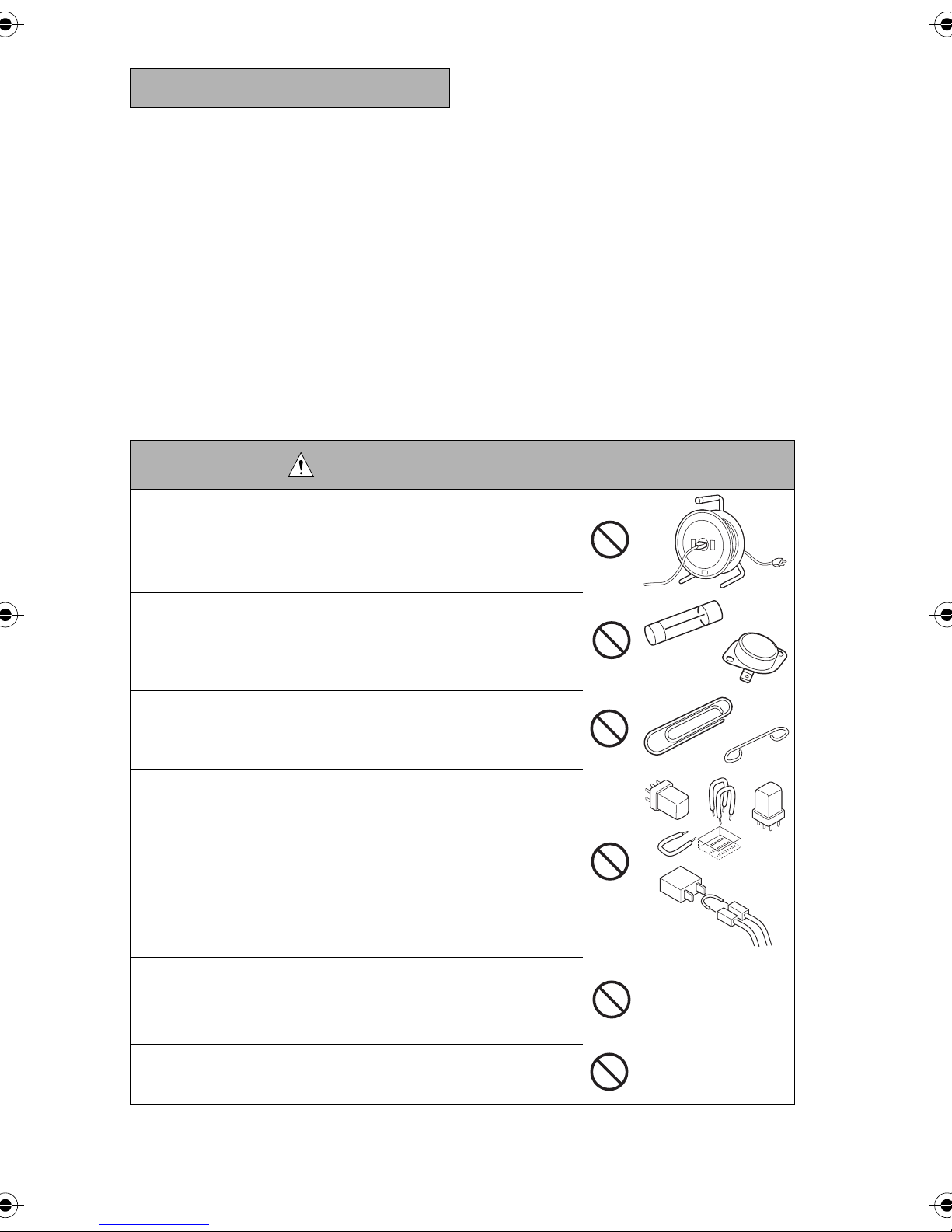
DANGER: PROHIBITED ACTIONS
• Using any cables or power cord not specified by NEC.
• Using any fuse or thermostat not specified by NEC. Safety
will not be assured, leading to a risk of fire and injury.
• Disabling fuse functions or bridging fuse terminals with
wire, metal clips, solder or similar object.
• Disabling relay functions (such as wedging paper between
relay contacts)
• Disabling safety functions (interlocks, safety circuits, etc.)
Safety will not be assured, leading to a risk of fire and
injury.
• Making any modification to the product unless instructed
by NEC.
P-2

DANGER: PROHIBITED ACTIONS
• Using parts not specified by NEC.
2. CHECKPOINTS WHEN PERFORMING ON-SITE SER-
VICE
NEC brand products are extensively tested before shipping, to ensure that all applicable
safety standards are met, in order to protect the customer and customer engineer (hereafter called the CE) from the risk of injury. However, in daily use, any electrical equipment
may be subject to parts wear and eventual failure. In order to maintain safety and reliability,
the CE must perform regular safety checks.
1. Power Supply
WARNING: Wall Outlet
• Check that mains voltage is as specified. Plug the power
cord into the dedicated wall outlet with a capacity greater
than the maximum power consumption.
If excessive current flows in the wall outlet, fire may
result.
• If two or more power cords can be plugged into the wall
outlet, the total load must not exceed the rating of the wall
outlet.
If excessive current flows in the wall outlet, fire may
result.
WARNING: Power Plug and Cord
• Make sure the power cord is plugged in the wall outlet
securely.
Contact problems may lead to increased resistance,
overheating, and the risk of fire.
P-3
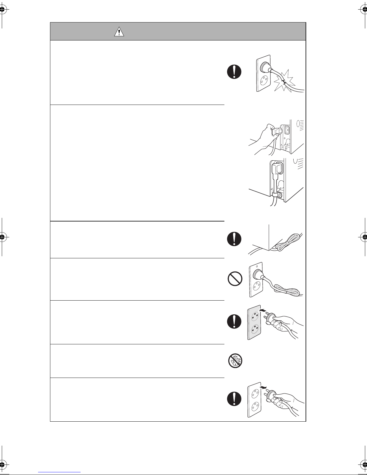
WARNING: Power Plug and Cord
• Check whether the power cord is damaged. Check
whether the sheath is damaged.
If the power plug, cord, or sheath is damaged, replace
with a new power cord (with plug and connector on each
end) specified by NEC. Using the damaged power cord
may result in fire or electric shock.
• When using the power cord (inlet type) that came with this
product, be sure to observe the following precautions:
a. Make sure the connector is securely inserted in the inlet
on the rear panel of the product.
Secure the cord with a fixture properly.
b. If the power cord or sheath is damaged, replace with a
new power cord (with plugs on both ends) specified by
NEC.
If the power cord (inlet type) is not connected to the
product securely, a contact problem may lead to
increased resistance, overheating, and risk of fire.
• Check whether the power cord is not stepped on or
pinched by a table and so on.
Overheating may occur there, leading to a risk of fire.
• Do not bundle or tie the power cord.
Overheating may occur there, leading to a risk of fire.
• Check whether dust is collected around the power plug
and wall outlet.
Using the power plug and wall outlet without removing
dust may result in fire.
• Do not insert the power plug into the wall outlet with a wet
hand.
The risk of electric shock exists.
• When unplugging the power cord, grasp the plug, not the
cable.
The cable may be broken, leading to a risk of fire and
electric shock.
P-4
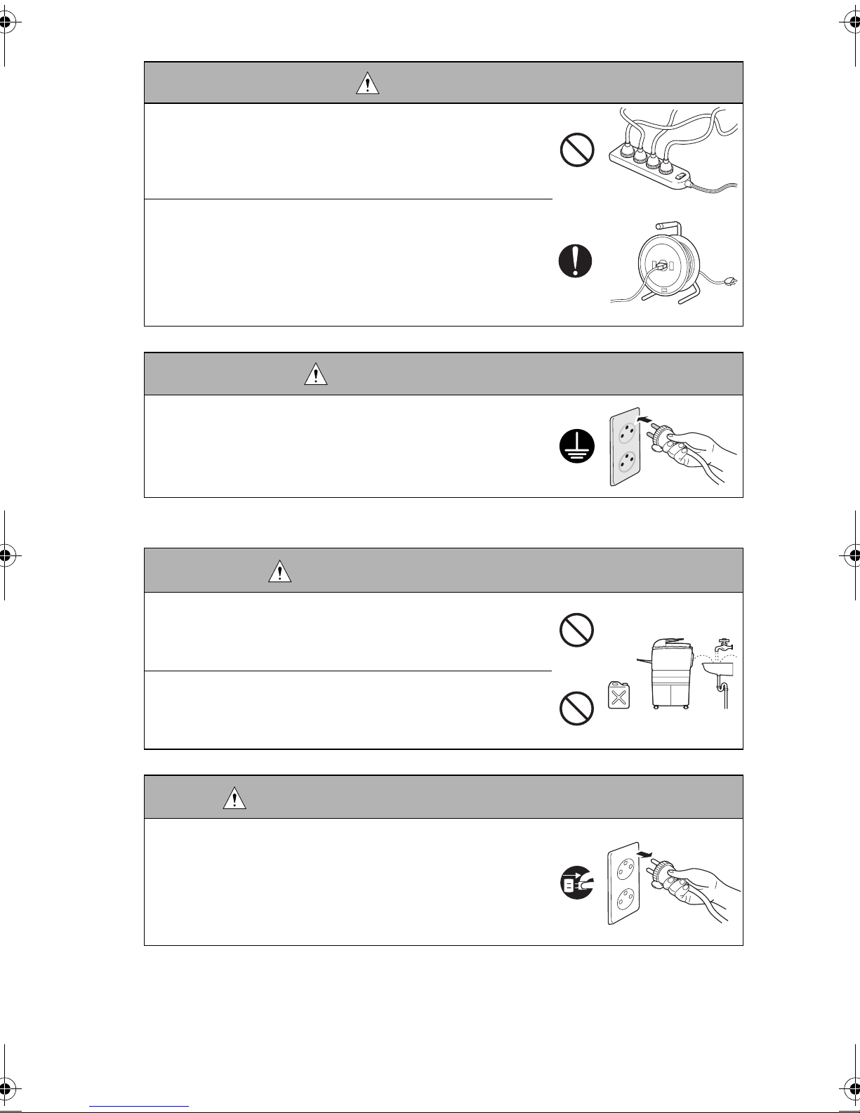
WARNING: Wiring
• Never use multi-plug adapters to plug multiple power
cords in the same outlet.
If used, the risk of fire exists.
• When an extension cord is required, use a specified one.
Current that can flow in the extension cord is limited, so
using a too long extension cord may result in fire.
Do not use an extension cable reel with the cable taken
up. Fire may result.
WARNING: Ground connection
• Check whether the product is grounded properly.
If current leakage occurs in an ungrounded product, you
may suffer electric shock while operating the product.
Connect power plug to grounded wall outlet.
2. Installation Requirements
WARNING: Prohibited Installation Place
• Do not place the product near flammable materials or volatile materials that may catch fire.
A risk of fire exists.
• Do not place the product in a place exposed to water such
as rain.
A risk of fire and electric shock exists.
WARNING: When not using product for a long time
• When the product is not used over an extended period of
time (holidays, etc.), switch it off and unplug the power
cord.
Dust collected around the power plug and outlet may
cause fire.
P-5
CAUTION: Ventilation
• The product generates ozone gas during operation, but it
will not be harmful to the human body.
If a bad smell of ozone is present in the following cases,
ventilate the room.
a. When the product is used in a poorly ventilated room
b. When taking a lot of copies
c. When using multiple products at the same time
CAUTION: Fixing
• Be sure to lock the caster stoppers.
In the case of an earthquake and so on, the product may
slide, leading to a injury.
CAUTION: Inspection before Servicing
• Before conducting an inspection, read all relevant docu-
mentation (service manual, technical notices, etc.) and
proceed with the inspection following the prescribed procedure, using only the prescribed tools. Do not make any
adjustment not described in the documentation.
If the prescribed procedure or tool is not used, the product may break and a risk of injury or fire exists.
• Before conducting an inspection, be sure to disconnect the
power plugs from the product and options.
When the power plug is inserted in the wall outlet, some
units are still powered even if the POWER switch is
turned OFF. A risk of electric shock exists.
• The area around the fixing unit is hot.
You may get burnt.
P-6
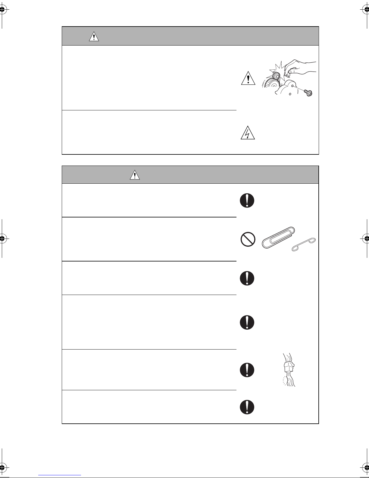
WARNING: Work Performed with the product Powered
• Take every care when making adjustments or performing
an operation check with the product powered.
If you make adjustments or perform an operation check
with the external cover detached, you may touch live or
high-voltage parts or you may be caught in moving gears
or the timing belt, leading to a risk of injury.
• Take every care when servicing with the external cover
detached.
High-voltage exists around the drum unit. A risk of electric shock exists.
WARNING: Safety Checkpoints
• Check the exterior and frame for edges, burrs, and other
damages.
The user or CE may be injured.
• Do not allow any metal parts such as clips, staples, and
screws to fall into the product.
They can short internal circuits and cause electric shock
or fire.
• Check wiring for squeezing and any other damage.
Current can leak, leading to a risk of electric shock or
fire.
• Carefully remove all toner remnants and dust from electrical parts and electrode units such as a charging corona
unit.
Current can leak, leading to a risk of product trouble or
fire.
• Check high-voltage cables and sheaths for any damage.
Current can leak, leading to a risk of electric shock or
fire.
• Check electrode units such as a charging corona unit for
deterioration and sign of leakage.
Current can leak, leading to a risk of trouble or fire.
P-7
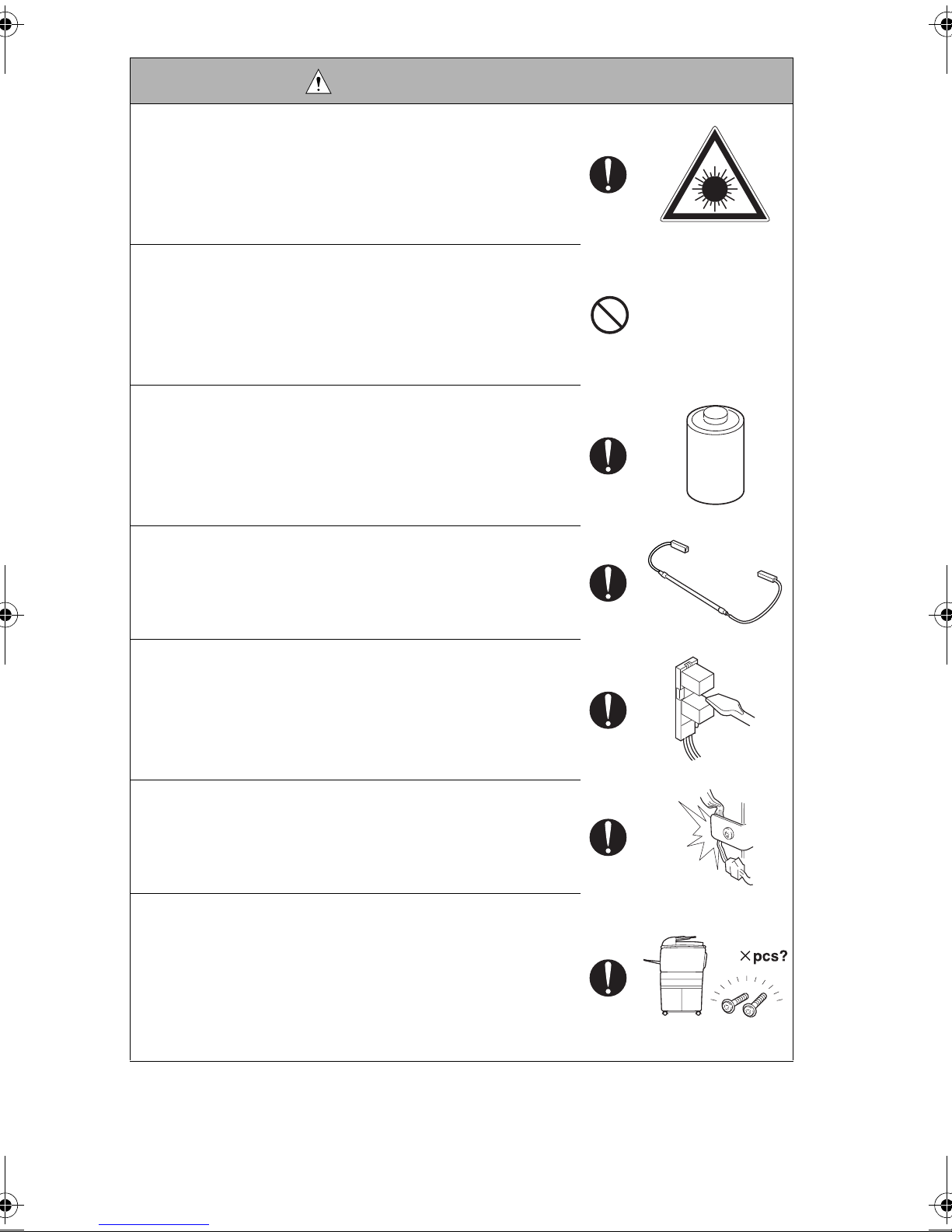
WARNING: Safety Checkpoints
• Before disassembling or adjusting the write unit (P/H unit)
incorporating a laser, make sure that the power cord has
been disconnected.
The laser light can enter your eye, leading to a risk of
loss of eyesight.
• Do not remove the cover of the write unit. Do not supply
power with the write unit shifted from the specified mounting position.
The laser light can enter your eye, leading to a risk of
loss of eyesight.
• When replacing a lithium battery, replace it with a new lithium battery specified in the Parts Guide Manual. Dispose
of the used lithium battery using the method specified by
local authority.
Improper replacement can cause explosion.
• After replacing a part to which AC voltage is applied (e.g.,
optical lamp and fixing lamp), be sure to check the installation state.
A risk of fire exists.
• Check the interlock switch and actuator for loosening and
check whether the interlock functions properly.
If the interlock does not function, you may receive an
electric shock or be injured when you insert your hand in
the product (e.g., for clearing paper jam).
• Make sure the wiring cannot come into contact with sharp
edges, burrs, or other pointed parts.
Current can leak, leading to a risk of electric shock or
fire.
• Make sure that all screws, components, wiring, connectors, etc. that were removed for safety check and maintenance have been reinstalled in the original location. (Pay
special attention to forgotten connectors, pinched cables,
forgotten screws, etc.)
A risk of product trouble, electric shock, and fire exists.
P-8

WARNING: HANDLING OF CONSUMABLE
• Toner and developer are not harmful substances, but care
must be taken not to breathe excessive amounts or let the
substances come into contact with eyes, etc. It may be
stimulative.
If the substances get in the eye, rinse with plenty of water
immediately. When symptoms are noticeable, consult a
physician.
• Never throw the used cartridge and toner into fire.
You may be burned due to dust explosion.
CAUTION: HANDLING OF SERVICE MATERIALS
• Unplug the power cord from the wall outlet.
Drum cleaner (isopropyl alcohol) and roller cleaner (acetone-based) are highly flammable and must be handled
with care. A risk of fire exists.
• Do not replace the cover or turn the product ON before
any solvent remnants on the cleaned parts have fully
evaporated.
A risk of fire exists.
• Use only a small amount of cleaner at a time and take care
not to spill any liquid. If this happens, immediately wipe it
off.
A risk of fire exists.
• When using any solvent, ventilate the room well.
Breathing large quantities of organic solvents can lead to
discomfort.
P-9

3. MEASURES TO TAKE IN CASE OF AN ACCIDENT
1. If an accident has occurred, the distributor who has been notified first must immediately
take emergency measures to provide relief to affected persons and to prevent further
damage.
2. If a report of a serious accident has been received from a customer, an on-site evaluation must be carried out quickly and NEC must be notified.
3. To determine the cause of the accident, conditions and materials must be recorded
through direct on-site checks, in accordance with instructions issued by NEC.
4. CONCLUSION
1. Safety of users and customer engineers depends highly on accurate maintenance and
administration. Therefore, safety can be maintained by the appropriate daily service
work conducted by the customer engineer.
2. When performing service, each product on the site must be tested for safety. The customer engineer must verify the safety of parts and ensure appropriate management of
the equipment.
P-10

5. Used Batteries Precautions
ALL Areas
CAUTION
Danger of explosion if battery is incorrectly replaced.
Replace only with the same or equivalent type recommended by the manufacturer.
Dispose of used batteries according to the manufacturer’s instructions.
Germany
VORSICHT!
Explosionsgefahr bei unsachgemäßem Austausch der Batterie.
Ersatz nur durch denselben oder einen vom Hersteller empfohlenen gleichwertigen Typ.
Entsorgung gebrauchter Batterien nach Angaben des Herstellers.
France
ATTENTION
Il y a danger d’explosion s’il y a remplacement incorrect de la batterie.
Remplacer uniquement avec une batterie du même type ou d’un type équivalent recommandé par le constructeur. Mettre au rebut les batteries usagées conformément aux
instructions du fabricant.
Denmark
ADVARSEL!
Lithiumbatteri - Eksplosionsfare ved fejlagtig håndtering.
Udskiftning må kun ske med batteri af samme fabrikat og type. Levér det brugte batteri tilbage til leverandøren.
Finland, Sweden
VAROlTUS
Paristo voi räjähtää, jos se on virheellisesti asennettu.
Vaihda paristo ainoastaan laitevalmistajan suosittelemaan tyyppiin. Hävitä käytetty paristo
valmistajan ohjeiden mukaisesti.
VARNING
Explosionsfara vid felaktigt batteribyte.
Använd samma batterityp eller en ekvivalent typ som rekommenderas av apparattillverkaren. Kassera använt batteri enligt fabrikantens instruktion.
Norway
Eksplosjonsfare ved feilaktig skifte av batteri.
Benytt samme batteritype eller en tilsvarende type anbefalt av apparatfabrikanten. Brukte
batterier kasseres i henhold til fabrikantens instruksjoner.
ADVARSEL
P-11

INDEX (Field Service)
GENERAL
MAINTENANCE
DIS/REASSEMBLY,
ADJUSTMENT
CONTROL PANEL/SERVICE
MODE DESCRIPTIONS
TROUBLESHOOTING

i
CONTENTS
GENERAL
1. SPECIFICATIONS ........................................................................................... G-1
1-1. Main Uint .................................................................................................. G-1
1-2. GDI Printer Function ................................................................................ G-3
1-3. FAX Function ............................................................................................ G-3
1-4. Network Function (NEFAX 691 only) ....................................................... G-5
2. PRECAUTIONS FOR INSTALLATION ............................................................ G-6
2-1. To Ensure THIS MACHINE is Used in an Optimum Condition ................ G-6
2-2. To Ensure the printer is Used in an Optimum Condition .......................... G-6
3. PRECAUTIONS FOR USE .............................................................................. G-7
3-1. To Ensure the Printer is Used in an Optimum Condition ......................... G-7
3-2. Operating Environment ............................................................................ G-7
3-3. Power Requirements ................................................................................ G-7
4. HANDLING OF THE CONSUMABLES ............................................................ G-8
5. MISCELLANEOUS PRECAUTIONS ................................................................ G-8
6. PARTS IDENTIFICATION ................................................................................ G-9
MAINTENANCE
1. MAINTENANCE SCHEDULE .......................................................................... E-1
1-1. Guidelines for Life Specifications Values by Unit ..................................... E-2
(1) Life Specifications Values ................................................................ E-2
2. REPLACEMENT/CLEANING OF PARTS ........................................................ E-3
(1) Cleaning of the Paper Take-Up Roller ............................................. E-3
(2) Replacement of the Paper Take-Up Roller ...................................... E-3
(3) Replacement of the Image Transfer Roller ...................................... E-4
3. REPLACEMENT OF UNITS ............................................................................ E-5
(1) Replacement of the Toner Cartridge ................................................ E-5
(2) Replacement of the Drum Cartridge ................................................ E-7
(3) Replacement of the Fusing Unit ....................................................... E-7
4. REPLACEMENT OF DOCUMENT FEEDER ................................................... E-10
(1) Cleaning of the Paper Take-Up Roller .............................................. E-10
(2) Replacement of the Paper Take-Up Roller....................................... E-10
(3) Cleaning of the Pick-Up Roller.......................................................... E-11
(4) Removal of the Pick-Up Roller.......................................................... E-12
(5) Cleaning of the Registration Rollers ................................................. E-12
(6) Cleaning of the Transport Roller....................................................... E-12
(7) Cleaning of the Exit Roller ................................................................ E-12
(8) Cleaning of the Paper Separator Pad............................................... E-13
(9) Removal of the Paper Separator Pad............................................... E-13
(10) Cleaning of the CIS and Shading roller............................................. E-14
(11) Removal of the CIS........................................................................... E-15
DIS/REASSEMBLY,ADJUSTMENT
1. SAFETY INFORMATION ................................................................................. D-1
1-1. Laser Safety ............................................................................................. D-1
1-2. Internal Laser Radiation ........................................................................... D-1
1-3. Laser Safety Label ................................................................................... D-4

ii
1-4. Laser Safety Label .................................................................................. D-4
1-5. Precautions for Handling the Laser Equipment ....................................... D-5
2. PRECAUTIONS FOR DISASSEMBLY/ADJUSTMENTS ................................ D-6
2-1. Parts That Must Not be Touched ............................................................ D-6
(1) Red Painted Screws ........................................................................ D-6
(2) Variable resistors on board ............................................................. D-6
(3) Other Screws not Marked with Red Paint ....................................... D-6
3. DISASSEMBLY/REASSEMBLY ...................................................................... D-7
3-1. Identification of Exterior Parts and Removal Procedures for Them ........ D-8
3-2. Name/Removal of External Parts ............................................................ D-8
3-3. Removal of the Circuit Boards and Other Eletrical Components...................D-9
3-4. Removal of Ciruit Boards ........................................................................ D-10
(1) Removal of the Network Interface Card Board................................. D-11
(2) Removal of the Network Control Unit Board D-11
(3) Removal of the Controller/Mechanical Control Board ..................... D-12
(4) Removal of the Control Panel ......................................................... D-12
(5) Removal of the Interface Board ....................................................... D-13
(6) Removal of the Plate NIC Board .................................................... D-14
(7) Removal of the Power Unit ............................................................. D-15
(8) Removal of the High Voltage Unit ................................................... D-16
3-5. Removal of Units ..................................................................................... D-17
(1) Removal of the ADF Unit ................................................................ D-17
(2) Removal of the PH Unit ................................................................... D-17
(3) Removal of the Automatic Document Feeder unit............................ D-21
(4) Removal of the Automatic Document Feeder Control...................... D-22
(5) Removal of the AFEIF Board ........................................................... D-22
(6) Removal of the Automatic Document Feeder Main Motor ............... D-23
3-6. Disassembly of the Main Drive Section ................................................... D-24
(1) Removal of the Main Motor ............................................................. D-24
(2) Removal of the Paper Empty Sensors ............................................ D-24
(3) Removal of the Paper Take-Up Solenoid ........................................ D-25
(4) Removal of the Paper Take-Up Clutch Gear ................................... D-27
(5) Removal of the Torque Limiter ........................................................ D-28
(6) Disassembly of the Fusing Unit ....................................................... D-29
4. ADJUSTMENTS .............................................................................................. D-31
4-1. Electrical/Image Adjustment .................................................................... D-31
(1) Accessing the Service Mode ........................................................... D-31
(2) Accessing the “ADJUST” Menu ....................................................... D-31
(3) Printing a Test Pattern .................................................................... D-31
(4) Margin Adjustment (Leading Edge/Trailing Edge/Both Sides) ........ D-32
(5) Printer’s Main Scanning Registration Adjustment ........................... D-33
(6) Printer’s Sub-Scanning Registration Adjustment ............................ D-34
(7) Leading Edge Tilt Adjustment .......................................................... D-35
(8) Automatic Document Feeder Sub-Scanning Zoom Ratio
Adjustment ..................................................................................... D-36
(9) Automatic Document Feeder Main-Scanning Registration
Adjustment ..................................................................................... D-37

iii
(10) Automatic Document Feeder Sub-Scanning Registration
Adjustment ....................................................................................... D-38
4-2. ADJUSTMENT OF JUMPER SWITCHES ON NCU BOARD ................... D-39
5. MISCELLANEOUS ........................................................................................... D-40
5-1. Updating the Firmware ............................................................................. D-40
(1) Installing the GDI Printer Driver/
TWAIN Driver Using Plug and Play ..................................................D-40
(2) Procedure for Upgrading the Firmware
(Engine firmware/ FAX firmware) ..................................................... D-42
5-2. Procedure for Upgrading the Firmware
(NIC Firmware NEFAX 691 only) ............................................................. D-45
5-3. Remedy for a Failed Updating of the Firmware ....................................... D-47
5-4. Moving the EEPROM ............................................................................... D-49
CONTROL PANEL/SERVICE MODE DESCRIPTIONS
1. CONTROL PANEL DESCRIPTIONS ............................................................... S-1
1-1. Names of Control Panel Parts and Their Functions ................................ S-1
2. FUNCTIONS OF SWITCHES AND PARTS ON PWBs ................................... S-4
2-1.. Circuit Board Locations NEFAX 671......................................................... S-4
2-2.. Circuit Board Locations NEFAX 691......................................................... S-4
2-3. PWB-P (Controller/Mechanical Control Board) ........................................ S-5
2-4. PWB-IF (Interface Board) ......................................................................... S-5
2-5. NCU (Network Control Unit Board) ......................................................... S-6
2-6. NIC (Network Interface Card Board) ........................................................ S-6
2-7. NIC-IF (Plate NIC Board) ........................................................................ S-6
(1)LED status display list ......................................................................... S-7
2-8. PWB-A ADF Board) ................................................................................ S-7
3. STATUS MODE ............................................................................................... S-8
3-1. Status Mode Function Tree ...................................................................... S-8
3-2. Status Mode Setting Procedure ............................................................... S-9
(1) Total Page ........................................................................................ S-10
(2) TX/ RX Result ................................................................................. S-10
(3) Print Report ..................................................................................... S-11
4. UTILITY MODE ) .............................................................................................. S-18
4-1. Utility Mode Function Tree (Outline) ........................................................ S-18
4-2. Utility Mode Function Tree (Details) ......................................................... S-19
4-3. Utility Mode Setting Procedure ................................................................. S-22
(1) Machine Setting ............................................................................... S-22
(2) Paper source setting ........................................................................ S-24
(3) Admin. management ........................................................................ S-25
(4) Copy setting ..................................................................................... S-27
(5) FAX registration ............................................................................... S-27
(6) TX operation .................................................................................... S-30
(7) RX operation .................................................................................... S-33
(8) Comm. setting .................................................................................. S-41
(9) Reporting ......................................................................................... S-44
(10) Initial user data ................................................................................. S-45

iv
(11) Network setting ................................................................................ S-46
(12) E-mail setting 1 ................................................................................ S-48
(13) E-mail setting 2 ................................................................................ S-50
(14) Scan setting ..................................................................................... S-52
5. SERVICE MODE ............................................................................................. S-54
5-1. Service Mode Function Tree(Outline) ...................................................... S-54
5-2. Service Mode Function Tree(Details) ...................................................... S-55
5-3. Service Mode Setting Procedure ............................................................. S-58
(1) <Procedure> .................................................................................... S-58
(2) <Exiting Procedure> ........................................................................ S-58
(3) <Changing the Settings for Service Mode Functions> .................... S-58
5-4. Service’s Choice Functions ..................................................................... S-59
(1) Marketing Area ................................................................................ S-60
(2) Shipment Destination ...................................................................... S-61
(3) Leading Edge Erase ........................................................................ S-62
(4) Trailing Edge Erase ......................................................................... S-62
(5) Vertical Edge Erase ......................................................................... S-63
(6) FLS Paper Size ............................................................................... S-63
(7) TX Speed ........................................................................................ S-63
(8) RX Speed ........................................................................................ S-63
(9) TX Level .......................................................................................... S-64
(10) RX Level .......................................................................................... S-64
(11) DTMF Level ..................................................................................... S-64
(12) CNG Level ....................................................................................... S-64
(13) CED Level ....................................................................................... S-65
(14) ECM Mode ...................................................................................... S-65
(15) Coding Scheme ............................................................................... S-65
(16) Toner Empty Report ........................................................................ S-66
(17) Protocol Report ............................................................................... S-67
(18) GDI Time out ................................................................................... S-67
(19) Toner Empty Stop ........................................................................... S-68
(20) Pre-rotation ...................................................................................... S-68
(21) Fuser Temp Ad. ............................................................................... S-68
5-5. Adjust Function ........................................................................................ S-69
(1) Adjust ............................................................................................ S-69
5-6. Counter Function ..................................................................................... S-70
(1) Counter ............................................................................................ S-70
5-7. Display Function ...................................................................................... S-73
(1) Display ............................................................................................ S-73
5-8. Soft Switch Function ................................................................................ S-74
5-9. Reporting ................................................................................................. S-75
(1) Service Data List ............................................................................. S-75
(2) Error Code List ................................................................................ S-78
(3) T.30 Protocol List ............................................................................ S-79
5-10.Admin. Registration (Administrator number registration) ........................ S-80
5-11.Fixed zoom change ................................................................................. S-81
(1) <Metric> .......................................................................................... S-81

v
(2) <Inch> ............................................................................................. S-81
5-12.Clear Data ................................................................................................ S-82
(1) DRAM clear ...................................................................................... S-82
(2) SRAM clear ...................................................................................... S-83
(3) Memory clear ................................................................................... S-85
(4) Total clear ........................................................................................ S-87
(5) Total counter..................................................................................... S-87
(6) PM counter (clear) ........................................................................... S-87
(7) I/C counter (clear) ............................................................................ S-87
(8) Application counter (clear) ............................................................... S-87
(9) Scan counter (clear) ......................................................................... S-87
6. Soft Switch Set ................................................................................................ S-88
6-1. Description ............................................................................................... S-88
6-2. Default setting .......................................................................................... S-89
(1) Country for each Marketing area ..................................................... S-89
6-3. Default soft switch setting for each market area 1 ................................... S-90
6-4. Default soft switch setting for each market area 2 ................................... S-92
6-5. Default soft switch setting for each market area 3 ................................... S-94
6-6. Default soft switch setting for each market area 4 ................................... S-96
6-7. Default soft switch setting for each market area 5 ................................... S-98
6-8. Default soft switch setting for each market area 6 ................................... S-100
6-9. Default soft switch setting for each market area 7 ................................... S-102
6-10.Default soft switch setting for each market area 8 ................................... S-104
6-11.Soft Switch List ........................................................................................ S-106
6-12.Soft Switch definition ................................................................................ S-110
(1) SOFT SWITCH: #01 ........................................................................ S-110
(2) SOFT SWITCH: #02 ........................................................................ S-111
(3) SOFT SWITCH: #03 ........................................................................ S-112
(4) SOFT SWITCH: #04 ........................................................................ S-113
(5) SOFT SWITCH: #05 ........................................................................ S-114
(6) SOFT SWITCH: #06 ........................................................................ S-115
(7) SOFT SWITCH: #07 ........................................................................ S-115
(8) SOFT SWITCH: #08 ........................................................................ S-116
(9) SOFT SWITCH: #09 ........................................................................ S-117
(10) SOFT SWITCH: #10 ........................................................................ S-118
(11) SOFT SWITCH: #11 ........................................................................ S-119
(12) SOFT SWITCH: #12 ........................................................................ S-119
(13) SOFT SWITCH: #13 ........................................................................ S-120
(14) SOFT SWITCH: #14 ........................................................................ S-121
(15) SOFT SWITCH: #15 ........................................................................ S-121
(16) SOFT SWITCH: #16 ........................................................................ S-122
(17) SOFT SWITCH: #17 ........................................................................ S-122
(18) SOFT SWITCH: #18 ........................................................................ S-123
(19) SOFT SWITCH: #19 ........................................................................ S-124
(20) SOFT SWITCH: #20 ........................................................................ S-125
(21) SOFT SWITCH: #21 ........................................................................ S-126
(22) SOFT SWITCH: #22 ........................................................................ S-127

vi
(23) SOFT SWITCH: #23 ........................................................................ S-127
(24) SOFT SWITCH: #24 ........................................................................ S-128
(25) SOFT SWITCH: #25 ........................................................................ S-128
(26) SOFT SWITCH: #26 ........................................................................ S-129
(27) SOFT SWITCH: #27 ........................................................................ S-130
(28) SOFT SWITCH: #28 ........................................................................ S-131
(29) SOFT SWITCH: #29 ........................................................................ S-132
(30) SOFT SWITCH: #30 ........................................................................ S-133
(31) SOFT SWITCH: #31 ........................................................................ S-134
(32) SOFT SWITCH: #32 ........................................................................ S-134
(33) SOFT SWITCH: #33 ........................................................................ S-135
(34) SOFT SWITCH: #34 ........................................................................ S-135
(35) SOFT SWITCH: #35 ........................................................................ S-136
(36) SOFT SWITCH: #36 ........................................................................ S-137
(37) SOFT SWITCH: #37 ........................................................................ S-138
(38) SOFT SWITCH: #38 ........................................................................ S-139
(39) SOFT SWITCH: #39 ........................................................................ S-139
(40) SOFT SWITCH: #40 ........................................................................ S-140
(41) SOFT SWITCH: #41 ........................................................................ S-141
(42) SOFT SWITCH: #42 ........................................................................ S-142
(43) SOFT SWITCH: #43 ........................................................................ S-142
(44) SOFT SWITCH: #44 ........................................................................ S-142
(45) SOFT SWITCH: #45 ........................................................................ S-143
(46) SOFT SWITCH: #46 ........................................................................ S-144
(47) SOFT SWITCH: #47 ........................................................................ S-144
(48) SOFT SWITCH: #48 ........................................................................ S-145
(49) SOFT SWITCH: #49 ........................................................................ S-146
(50) SOFT SWITCH: #50 ........................................................................ S-146
(51) SOFT SWITCH: #51 ........................................................................ S-147
(52) SOFT SWITCH: #52 ........................................................................ S-147
(53) SOFT SWITCH: #53 ........................................................................ S-148
(54) SOFT SWITCH: #54 ........................................................................ S-148
(55) SOFT SWITCH: #55 ........................................................................ S-149
(56) SOFT SWITCH: #56 ........................................................................ S-149
(57) SOFT SWITCH: #57 ........................................................................ S-149
(58) SOFT SWITCH: #58 ........................................................................ S-150
(59) SOFT SWITCH: #59 Part 1 ............................................................. S-151
(60) SOFT SWITCH: #59 Part 2 ............................................................. S-152
(61) SOFT SWITCH: #59 Part 3 ............................................................. S-153
(62) SOFT SWITCH: #60 ........................................................................ S-154
(63) SOFT SWITCH: #61 ........................................................................ S-154
(64) SOFT SWITCH: #62 ........................................................................ S-155
(65) SOFT SWITCH: #63 ........................................................................ S-155
(66) SOFT SWITCH: #64 ........................................................................ S-156
7. Fax Protocols ................................................................................................... S-157
7-1. G3 ECM (G3 Error Correction Mode) ...................................................... S-157
7-2. Line Control ............................................................................................. S-158

vii
(1) Procedure of G3 mode communication ........................................... S-158
7-3. Table of reference code ........................................................................... S-159
7-4. How to analyze the T30 protocol monitor ................................................. S-160
TROUBLESHOOTING
1. INTRODUCTION .............................................................................................. T-1
1-1. Electric Components Check Procedures ................................................. T-1
(1) Sensors ............................................................................................ T-1
(2) Switches ........................................................................................... T-2
(3) Solenoids ......................................................................................... T-2
(4) Motors ............................................................................................. T-3
(5) Clutches ........................................................................................... T-4
1-2. Overall Control Configuration ................................................................... T-5
2. PAPER MISFEED ............................................................................................ T-6
2-1. Initial Check Items .................................................................................... T-6
2-2. ADF Unit Initial Check Items .................................................................... T-6
2-3. Paper Misfeed Displays ........................................................................... T-7
2-4. ADF Unit Paper Misfeed Displays ............................................................ T-8
2-5. Locations of Misfeed Detection Sensors .................................................. T-9
2-6. ADF Unit Locations of Misfeed Detection Sensors .................................. T-10
2-7. Misfeed Detection Timing and Troubleshooting Procedures ................... T-11
(1) Paper Take-Up/Transport Misfeed ................................................... T-11
(2) Fusing/Exit Misfeed .......................................................................... T-12
3. PAPER MISFEED(Document Feeder Section)................................................. T-13
(1) The Original Timing ................................................................................... T-13
4. MALFUNCTIONS/WARNING .......................................................................... T-14
4-1. List of Malfunctions .................................................................................. T-14
4-2. Malfunction Detection Timing and Troubleshooting Procedures .............. T-16
(1) C0045: Fuser fan motor error .......................................................... T-16
(2) C0210: H.V. abnormal ..................................................................... T-17
(3) C0500: Fuser warm up error ............................................................ T-18
(4) C0510: Fuser temperature low ........................................................ T-19
(5) C0520: Fuser overheat .................................................................... T-20
(6) C1200: ASIC memory abnormal ...................................................... T-21
(7) C1300: Polygon mirror motor error .................................................. T-21
(8) C133B: Communication with option error ........................................ T-22
(9) C133C: Modem error ....................................................................... T-22
(10) C133D: ROM checksum error .......................................................... T-22
(11) C13F0: Laser error ........................................................................... T-23
(12) C1468: EEPROM error .................................................................... T-23
(13) C14A3: CIS LED malfunction ........................................................... T-24
5. MALFUNCTIONS RELATED TO POWER SUPPLY ....................................... T-25
5-1. Power is not Turned ON. .......................................................................... T-25
6. IMAGE QUALITY PROBLEMS ........................................................................ T-26
6-1. Troubleshooting Image Quality Problems ................................................ T-26
6-2. Initial Checks ............................................................................................ T-26

viii
6-3. Troubleshooting for Specific Image Quality Problems ............................. T-27
(1) Image reading system: Blank or black prints ................................... T-28
(2) Image reading system: Low image density ...................................... T-29
(3) Image reading system: Foggy background or rough image ............. T-30
(4) Image reading system: Black streaks or bands ............................... T-31
(5) Image reading system: Black spots ................................................. T-31
(6) Image reading system: Blank streaks or bands ............................... T-32
(7) Printer system: Blank or black prints ................................................ T-33
(8) Printer system: Blank spots ............................................................. T-34
(9) Printer system: Smears on back ...................................................... T-34
(10) Printer system: Low image density .................................................. T-35
(11) Printer system: Foggy background .................................................. T-36
(12) Printer system: Blank streaks or bands ........................................... T-36
(13) Printer system: Black streaks or bands ............................................ T-37
(14) Printer system: Offset image ............................................................ T-37
7. FAX Error ) ....................................................................................................... T-38
7-1. Communication Error ............................................................................... T-38
(1) Outline ............................................................................................. T-38
(2) Error occurring during transmission ................................................. T-38
(3) Error occurring during reception ...................................................... T-38
7-2. Error Code ................................................................................................ T-39
(1) Reception ......................................................................................... T-39
(2) Transmission .................................................................................... T-41
8. TROUBLESHOOTING ) ................................................................................... T-45
8-1. Troubleshooting Procedure Overview ...................................................... T-45
8-2. Troubleshooting Procedure Chart ............................................................. T-45
8-3. Main Error Messages and Their Remedies .............................................. T-46
8-4. Troubleshooting Functions ....................................................................... T-47
8-5. List Communication Error Codes .............................................................. T-51

G-1
1. SPECIFICATIONS
1-1. Main Unit
Copy Medium
NOTE
The dimension for Tray2 is fixed at A4L or Letter L.
Type
Original scanning system
Photo conductor type
Copying system
Resolution
Paper feed-in system
Exposure system
Developing system
Drum-charging system
Image transfer system
Paper separation system
Fusing system
Max. Original size
Memory Capacity
:
:
:
:
:
:
:
:
:
:
:
:
:
:
Desktop
Scanning in main scanning direction with a CIS (Contact
Image System) sensor.
OPC (Organic Photo conductor)
Electrostatic dry Powdered image transfer to plain paper with
laser
600 dpi × 600 dpi, 600 dpi × 300 dpi
2-Way system (Tray1 and Bypass Tray)
*3-Way system is possible if optional PF-125 (Tray2) is
installed.
Unit scanning slit exposure
FMT (Fine Micro Toning) single component developing
Rotating brush with pre-charge film
Roller transfer
Curvature separation + Charge Neutralizing needle
Heat roller
Up to Legal size
STD: 16 MB (48 MB Maximum with 32 MB Option Memory:
NEFAX 691 only)
Paper source Tray1 Tray2 Bypass Tray
Type
Plain paper (60 to 90 g/m
2
)
(16 to 24 lb.)
❍❍❍
Recycled paper (60 to 90 g/m
2
)
(16 to 24 lb.)
❍❍❍
Special paper (91 to 163 g/m
2
)
(24 to 43 lb.)
❍ – ❍
Transparencies ❍ – ❍
Label sheets ❍ – ❍
Envelopes ❍ – ❍
Dimension
Maximum (width × length) 216×356 mm
A4 L, Letter L
216×356 mm
Minimum (width × length) 105×148 mm 105×148 mm

G-2
Zoom Ratios
Power /Current Consumption (main unit only)
copy speed (copies/min.)
Continuous print speed
(sheets/min.)
Warm-up time
:
:
:
:
16 copies/minute (at full size and 600 dpi × 300 dpi, with
ADF)
More than 16 sheets/minute (with plain A4 L or Letter L
paper)
Less than 25 seconds (at a room temperature of 23 °C and
at the rated voltage)
Metric Size (Inch Size)
Fixed
Full size ×1.00 ×1.00
Enlargement
×1.15
×1.41
×2.00
×1.29
×1.54
×2.00
Reduction
×0.81
×0.70
×0.50
×0.78
×0.64
×0.50
Var iabl e ×0.50 to ×2.00 (in ×0.01 increments)
Fusing temperature : 200 °C
Voltage Maximum power consumption
110 V, 120-127 V 770-890 W
220-240 V 740-850 W
Power source : 110 V, 120V-127 V, 220-240 V 50/60 Hz
Main unit dimensions
(including Automatic document feeder)
weight
Original type
Orignal capacity
Registration
Original loading orientation
Scan speed
:
:
:
Width....416 mm
Depth....419 mm
Height...408 mm
12kg
Plain paper: 35 to 128 g/m
2
(9 to 34 lb.)
width: 148 to 216 mm; length: 140 to 1000 mm
Maximum 50 sheets (80 g/m
2
)
Center
Face up
2.5sec(plain A4L,with standard mode of orginal feeding
Original types Possible problems
Originals bound with staples or
paper clips
Incorrect paper take-up, damaged originals or drive malfunctions due to jammed paper clips
Originals bound with glue Incorrect paper take-up or damaged originals
Folded, torn or extremely wrinkled originals
Incorrect paper take-up or damaged originals
Curled originals (more than 10
mm from front edge)
Paper misfeeds due to folded or skewed originals

G-3
1-2. GDI Printer Function
1-3. FAX Function
RAM
Interfaces
Printer Language
Fonts
Supported Operating
Systems
Web Browser
:
:
:
:
:
:
Share with main unit.
USB Revision 1.1
(except for Windows 95 and Windows NT)
GDI
Windows
Windows XP (SP1 or later)/Windows 2000 (SP3 or later)/
Windows Me/Windows 98 Second Edition/
Internet Explorer 4.0 or later
General
Compatibility : Super G3/ G3/ ECM (Error correction mode)
Scanning Resolution : STD: 204x98( 3.85 lines/mm)
Fine: 204x196(7.7 lines/mm)
Super Fine: 204x392(15.4 lines/mm)
Line : PSTN/ PBX
Data Transmission Rate : 33.6 kbps(4 Second : NEFAX 671)
33.6 kbps(3 Second : NEFAX 691)
*ITU-T No.1, A4 size, Normal resolution without header.
Coding Method : MH/ MR/ MMR/ JBIG (NEFAX 691 only)
Scanning Area : Sheet through scanning
Maximum 208mm
Internet fax : Enable (NEFAX 691 only)
Dialing
Direct dialing : Entering the fax number directly using the 10-Key Pad.
One touch dial : 32keys: NEFAX 671
64keys: NEFAX 691
Speed dial : 100 fax numbers: NEFAX 671
200 fax numbers: NEFAX 691
Group dial : 32 groups: NEFAX 671
64 groups: NEFAX 691
Program dial : NO/4 keys (No. 61,62,63,64)
Other dialing : Pause insert, Phone Book dial, On-hook dial,
Automatic redial, Redial, Chain dial, Combination dial

G-4
Transmission
Transmission mode : ADF TX, Memory TX, Batch TX, Broadcast TX,
Confidential Mailbox TX,
F code TX (SubAddress TX, SID TX), Forward TX
Manual TX, Polling TX, Quick Memory TX, Book TX,
Relay initiate TX, Reservation TX, Timer TX,
TX resolution mode/ TX
image mode
: Standard (204 dpi x 98 dpi),
Fine (204 dpi x 196 dpi),
Super fine (204 dpi x 392 dpi),
Standard + halftone (204 dpi x 98 dpi),
Fine + halftone (204 dpi x 196 dpi),
Super fine + halftone (204 dpi x 392 dpi)
Receiving
Receiving mode : Auto RX, Closed network RX, Confidential Mailbox RX,
Inward Polling RX, Manual RX, Memory RX, Substitute RX,
RX resolution : 204 dpi x 98 dpi, 204 dpi x 196 dpi, 204 dpi x 392 dpi,406 dpi
x 392 dpi
Max. recording paper
size
: A4/ Legal
Report : Activity report, Back up RAM error report,
G3 protocol monitor report, Memory image print,
Power failure report, Reservation report, RX result report,
Service report, TX result report,
List : Key setting list, Machine status list, Memory data list,
One-touch dial list, Service data list, Speed dial list,
Other Features : Automatic paper selection, Backup of memory,
Confirmation of communication result, Daylight saving time,
Date/Time setting, Display of destination station, Footer,
Header, Package reception printing, Pause insert,
Quick memory printing, Remote monitor, RX print cancel,
RX printing mode (100 %reception/ Reception print mode/
Cut mode), Separate print, Smoothing, Speaker, Time zone,
Tone signal transmission, TX cancel, RX cancel

G-5
1-4. Network Function (NEFAX 691 only)
Interface
Data format
Content Type
I-FAX Communication Protocol
I-FAX Data Format
I-FAX Cording method
I-FAX TX resolution
I-FAX RX resolution
Scan to E-Mail / Scan to FTP
Communication Protocol
Scan to E-Mail / Scan to FTP
Data Format
Scan to E-Mail / Scan to FTP
Cording method
Scan to E-Mail / Scan to FTP
resolution
:
:
:
:
:
:
:
:
:
:
:
:
Ethernet 10/100Base T /TX (RJ-45)
MIME, Base64
Multi-part/Mixed (text/plain, image/tiff)
TX: SMTP
RX: POP3
E-Mail Format: MIME
Attached File format: TIFF-F
Transmission: MH
Reception: MH, MR, MMR, JBIG
204 dpi × 98 dpi
204 dpi × 196 dpi
204 dpi × 98 dpi
204 dpi × 196 dpi
204 dpi × 392 dpi
200 dpi × 100 dpi
200 dpi × 200 dpi
E-Mail TX: SMTP
FTP TX: FTP
E-Mail Format: MIME
Attached File format: TIFF, PDF
MH, MR, MMR, JPEG (For Color and Gray mode, fixed
at JPEG)
150 dpi × 150 dpi
300 dpi × 300 dpi
600 dpi × 600 dpi

G-6
2. PRECAUTIONS FOR INSTALLATION
2-1. Installation Site
To ensure utmost safety and avoid breakdown, this machine should NOT be used in a
place:
• Where it will be subjected to extremely high or low temperature or humidity.
• Where it will be subjected to sudden fluctuations in either temperature or humidity.
• Which is exposed to direct sunlight.
• Which is in the direct air stream of an air conditioner, heater, or ventilator.
• Which has poor ventilation or is dusty.
• Which does not have a stable, level floor or where it will receive undue vibration.
• Which is near any kind of heating device.
• Which is near volatile flammables (thinner, gasoline, etc.).
• Where it may be splashed with water and electric leakage is likely to occur.
• Which puts the operator in the direct stream of exhaust from this machine.
• Where ammonia gas might be generated.
2-2. Power Source
• If any other electrical equipment is sourced from the same power outlet, make sure that
the capacity of the outlet is not exceeded.
• Use a power source with little voltage fluctuation.
• Never connect by means of a multiple socket any other appliances or machines to the
outlet being used for this machina.
• Ensure that this machine does not ride on the power cord or communications cable of
other electric equipment, and that it does not become wedged into or underneath the
mechanism.
• Make the following checks at frequent intervals:
✽ Is the power plug abnormally hot?
✽ Are there any cracks or scrapes in the cord?
✽ Has the power plug been inserted fully into the outlet?
✽ Does something, including this machine itself, ride on the power cord?
Use an outlet with a capacity of 110/120/127 V, or 220-240 V.

G-7
3. PRECAUTIONS FOR USE
3-1. To Ensure this Machine is Used in an Optimum Condition
• Never place a heavy object on this machine or subject this machine to shocks.
• Insert the power plug all the way into the outlet.
• Do not attempt to remove any panel or cover that is secured while this machine is in a
print cycle.
• Do not turn OFF this machine while it is in a print cycle.
• Provide good ventilation if this machine is to be used for a long time in a narrow room.
• Never use flammable sprays near this machine.
• If this machine becomes inordinately hot or produces abnormal noise, immediately turn it
OFF and unplug it.
• Do not turn ON the power switch at the same time that you plug the power cord into the
outlet.
• When unplugging the power cord, do not pull on the cord; hold the plug and pull it out.
• Do not bring any magnetized object near this machine.
• Do not place a vase or vessel containing water on this machine.
• Be sure to turn OFF the power switch at the end of the workday or upon power failure.
• Use care not to drop paper clips, staples, or other small pieces of metal into this
machine.
3-2. Operating Environment
The operating environmental requirements of this machine are as follows.
• Temperature: 10 to 30 °C
• Humidity: 15 to 85 %
• Rate of temperature change: 10 °C/h
• Rate of humidity change: 20 % Rh/h
3-3. Power Requirements
The power source voltage requirements are as follows.
• Voltage fluctuation: AC110 V - AC127 V -10 %, +6 % (Copying performance assured)
AC 220 V - AC 240 V ±10 % (Copying performance assured)
AC 110 V - AC 127 V -10 %, +6 % (Paper feeding performance
assured)
AC 220 V - AC 240 V ±10 % (Paper feeding performance assured)
• Frequency fluctuation: 50/60 Hz ± 3 Hz

G-8
4. HANDLING OF THE CONSUMABLES
Before using any consumables, always read the label on its container carefully.
• Paper can easily damp. To prevent absorption of moisture, store paper in a place with lit-
tle moisture.
• Keep consumables out of the reach of children.
• Do not touch the PC Drum with bare hands.
• The same sized paper is of two kinds, short grain and long grain. Short grain paper
should only be fed through this machine crosswise, while long grain paper should only be
fed lengthwise. The wrapper of the paper is properly marked.
• If your hands become soiled with toner, wash them with soap and water.
• Do not throw away any used consumables. They are to be collected.
• Do not burn, bury in the ground, or throw into the water any consumables.
• Do not store consumables in a place which:
✽ Is hot and humid.
✽ Is subject to direct sunlight.
✽ Has an open flame nearby.
5. MISCELLANEOUS PRECAUTIONS
Use the following precautions when performing service jobs for the machine that uses a
laser.
• When a service job needs to be performed in the laser beam path, such as when working
around the Print Head Unit or PC Drum, be sure first to unplug the power cord of the
machine from the outlet.
• If the service job requires that the power cord be left plugged in, observe the following
precautions:
1. Take off your watch, ring, and any other reflective object and wear laser protective gog-
gles.
2. Keep users away from the job site.
3. Do not bring a highly reflective tool into the laser beam path during the service job.
G-9
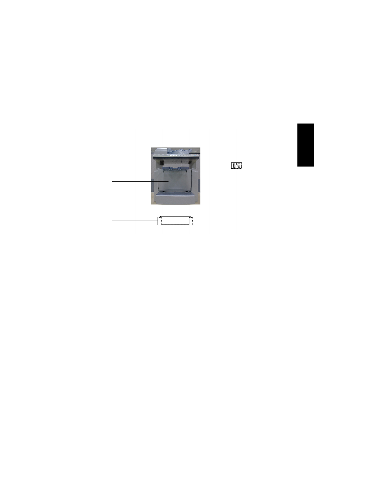
6. PARTS IDENTIFICATION
1
2
3
1. Main Unit NEFAX 671/
NEFAX 691
2. Paper Feed Cassette PF-
125
3. Expansion memory 32-5 (32
MB): NEFAX 691 only
 Loading...