

Page 1

MA4000
Installation Manager
User Guide
NEC
NEC Infrontia, Inc.
August 2008
NDA-30580, Revision 7
Page 2

Liability Disclaimer
NEC Infrontia, Inc. reserves the right to change the specifications,
functions, or features, at any time, without notice.
NEC Infrontia, Inc. has prepared this document for the exclusive use of
its employees and customers. The information contained herein is the
property of NEC Infrontia, Inc. and shall not be reproduced without
prior written approval from NEC Infrontia, Inc.
NEAX®, Dterm®, and UNIVERGE® are
registered trademarks of NEC Corporation.
© 2003-2008 NEC Infrontia, Inc.
MSDE®, Windows®, and Microsoft® are
registered trademarks of Microsoft Corporation.
Linux® is a registered trademark of Linus Torvaids.
Pentium® is a registered trademark of Intel Corporation
All other brand or product names are or may be trademarks or
registered trademarks of, and are used to identify products or services
of, their respective owners.
Page 3

Contents
i
Introduction 1-1
MA4000 Installation Manager Overview . . . . . . . . . . . . . . . . . . . . . . . . . . . . . . 1-1
How This Guide is Organized . . . . . . . . . . . . . . . . . . . . . . . . . . . . . . . . . . . . . . 1-2
MA4000 Installation Manager Application Abbreviations . . . . . . . . . . . . . . . . . 1-3
Getting Started 2-1
Requirements . . . . . . . . . . . . . . . . . . . . . . . . . . . . . . . . . . . . . . . . . . . . . . . . . . 2-1
MA4000 Installation Manager Installation . . . . . . . . . . . . . . . . . . . . . . . . . . . . . 2-3
Initializing the Flash Card and Installing the System Software
(SV7000 MPS Only) . . . . . . . . . . . . . . . . . . . . . . . . . . . . . . . . . . . . . . . . . . . . . 2-7
Introduction and Requirements. . . . . . . . . . . . . . . . . . . . . . . . . . . . . . . . . . . . . 2-7
Major Tasks . . . . . . . . . . . . . . . . . . . . . . . . . . . . . . . . . . . . . . . . . . . . . . . . . . . 2-7
Step-by-Step Procedure . . . . . . . . . . . . . . . . . . . . . . . . . . . . . . . . . . . . . . . . . . 2-8
Graphical User Interface 3-1
General Graphical User Interface Features . . . . . . . . . . . . . . . . . . . . . . . . . . . 3-1
Data Navigator . . . . . . . . . . . . . . . . . . . . . . . . . . . . . . . . . . . . . . . . . . . . . . . . . 3-1
Selecting . . . . . . . . . . . . . . . . . . . . . . . . . . . . . . . . . . . . . . . . . . . . . . . . . . . . . . 3-3
List Box Sorting. . . . . . . . . . . . . . . . . . . . . . . . . . . . . . . . . . . . . . . . . . . . . . . . . 3-4
Startup Dialog . . . . . . . . . . . . . . . . . . . . . . . . . . . . . . . . . . . . . . . . . . . . . . . . . . 3-5
Projects Tab . . . . . . . . . . . . . . . . . . . . . . . . . . . . . . . . . . . . . . . . . . . . . . . . . . . 3-6
Templates Tab . . . . . . . . . . . . . . . . . . . . . . . . . . . . . . . . . . . . . . . . . . . . . . . . 3-21
MA4000 Installation Manager User Guide - Revision 7
Page 4

ii Contents
Pull-Down Menus . . . . . . . . . . . . . . . . . . . . . . . . . . . . . . . . . . . . . . . . . . . . . . 3-24
File Menu . . . . . . . . . . . . . . . . . . . . . . . . . . . . . . . . . . . . . . . . . . . . . . . . . . . . 3-24
Edit Menu . . . . . . . . . . . . . . . . . . . . . . . . . . . . . . . . . . . . . . . . . . . . . . . . . . . . 3-24
Tools Menu . . . . . . . . . . . . . . . . . . . . . . . . . . . . . . . . . . . . . . . . . . . . . . . . . . . 3-25
Help Menu. . . . . . . . . . . . . . . . . . . . . . . . . . . . . . . . . . . . . . . . . . . . . . . . . . . . 3-44
Primary Sections . . . . . . . . . . . . . . . . . . . . . . . . . . . . . . . . . . . . . . . . . . . . . . . 3-45
Project Information 4-1
Primary Contact Tab . . . . . . . . . . . . . . . . . . . . . . . . . . . . . . . . . . . . . . . . . . . . . 4-2
Company Organization Tab. . . . . . . . . . . . . . . . . . . . . . . . . . . . . . . . . . . . . . . . 4-4
Tasks Tab . . . . . . . . . . . . . . . . . . . . . . . . . . . . . . . . . . . . . . . . . . . . . . . . . . . . 4-11
Phased Installation Tab . . . . . . . . . . . . . . . . . . . . . . . . . . . . . . . . . . . . . . . . . . 4-15
Hardware Information 5-1
Options Tab . . . . . . . . . . . . . . . . . . . . . . . . . . . . . . . . . . . . . . . . . . . . . . . . . . . . 5-2
Media Gateway and Circuit Cards. . . . . . . . . . . . . . . . . . . . . . . . . . . . . . . . . . . 5-9
Circuit Card Field Definitions . . . . . . . . . . . . . . . . . . . . . . . . . . . . . . . . . . . . . 5-13
Signaling Server - SIP Server (Including MPH) . . . . . . . . . . . . . . . . . . . . . . . 5-19
Voice Mail Tab . . . . . . . . . . . . . . . . . . . . . . . . . . . . . . . . . . . . . . . . . . . . . . . . . 5-22
Voice Mail System . . . . . . . . . . . . . . . . . . . . . . . . . . . . . . . . . . . . . . . . . . . . . 5-23
Exchange Information . . . . . . . . . . . . . . . . . . . . . . . . . . . . . . . . . . . . . . . . . . . 5-24
Active DIrectory Information . . . . . . . . . . . . . . . . . . . . . . . . . . . . . . . . . . . . . . 5-24
Voice Mail Station Ports . . . . . . . . . . . . . . . . . . . . . . . . . . . . . . . . . . . . . . . . . 5-24
Security Tab. . . . . . . . . . . . . . . . . . . . . . . . . . . . . . . . . . . . . . . . . . . . . . . . . . . 5-26
Terminal/Equipment Security . . . . . . . . . . . . . . . . . . . . . . . . . . . . . . . . . . . . . 5-27
MA4000 Installation Manager User Guide - Revision 7
Page 5

Contents iii
System Information 6-1
Station Ranges Tab . . . . . . . . . . . . . . . . . . . . . . . . . . . . . . . . . . . . . . . . . . . . . . 6-2
Access Codes Tab. . . . . . . . . . . . . . . . . . . . . . . . . . . . . . . . . . . . . . . . . . . . . . . 6-7
Speed Calling Tab . . . . . . . . . . . . . . . . . . . . . . . . . . . . . . . . . . . . . . . . . . . . . . . 6-9
Advanced Features 7-1
System Features (ASYD) Tab . . . . . . . . . . . . . . . . . . . . . . . . . . . . . . . . . . . . . . 7-2
Feature Restrictions Tab . . . . . . . . . . . . . . . . . . . . . . . . . . . . . . . . . . . . . . . . . . 7-5
Route Restrictions Tab . . . . . . . . . . . . . . . . . . . . . . . . . . . . . . . . . . . . . . . . . . . 7-9
Least Cost Routing (LCR) Tab . . . . . . . . . . . . . . . . . . . . . . . . . . . . . . . . . . . . 7-17
Automated Call Distribution (ACD) Tab . . . . . . . . . . . . . . . . . . . . . . . . . . . . . . 7-23
Open Application Interface (OAI) Tab . . . . . . . . . . . . . . . . . . . . . . . . . . . . . . . 7-25
Monitor Number Tab . . . . . . . . . . . . . . . . . . . . . . . . . . . . . . . . . . . . . . . . . . . . 7-28
User Assignments 8-1
User Assignments - New or Edit User . . . . . . . . . . . . . . . . . . . . . . . . . . . . . . . 8-6
Group Assignments 9-1
Circuit Card Assignments 10-1
Install 11-1
MA4000 Installation Manager User Guide - Revision 7
Page 6

iv Contents
Reports 12-1
Creating and Printing a Report or DESI Label . . . . . . . . . . . . . . . . . . . . . . . . 12-2
Productivity Features 13-1
Configuration Tab . . . . . . . . . . . . . . . . . . . . . . . . . . . . . . . . . . . . . . . . . . . . . . 13-2
UC Suite - MA4000 Manager . . . . . . . . . . . . . . . . . . . . . . . . . . . . . . . . . . . . . 13-4
Location Diversity . . . . . . . . . . . . . . . . . . . . . . . . . . . . . . . . . . . . . . . . . . . . . . 13-7
Management Tab. . . . . . . . . . . . . . . . . . . . . . . . . . . . . . . . . . . . . . . . . . . . . . 13-28
Diagnostic Tab. . . . . . . . . . . . . . . . . . . . . . . . . . . . . . . . . . . . . . . . . . . . . . . . 13-29
Maintenance Tab . . . . . . . . . . . . . . . . . . . . . . . . . . . . . . . . . . . . . . . . . . . . . . 13-30
MA4000 Installation Manager User Guide - Revision 7
Page 7

Figures
Figure Title Page
v
2-1 Run . . . . . . . . . . . . . . . . . . . . . . . . . . . . . . . . . . . . . . . . . . . . . . . . . . . . . 2-3
2-2 Installation Manager R25 - InstallShield Wizard Welcome . . . . . . . . . . . 2-4
2-3 Installation Manager R25 - InstallShield Wizard Complete . . . . . . . . . . . 2-5
2-4 Installation Manager R25 - InstallShield Install Feature(s) . . . . . . . . . . . 2-6
3-1 Data Navigator Single Select example . . . . . . . . . . . . . . . . . . . . . . . . . . 3-1
3-2 Data Navigator Multi Select example. . . . . . . . . . . . . . . . . . . . . . . . . . . . 3-2
3-3 List Box Contiguous Select example . . . . . . . . . . . . . . . . . . . . . . . . . . . . 3-3
3-4 List Box Multi-Select example . . . . . . . . . . . . . . . . . . . . . . . . . . . . . . . . . 3-3
3-5 Edit Multiple Records example . . . . . . . . . . . . . . . . . . . . . . . . . . . . . . . . 3-4
3-6 List Box Sorting example . . . . . . . . . . . . . . . . . . . . . . . . . . . . . . . . . . . . . 3-4
3-7 Installation Manager Startup . . . . . . . . . . . . . . . . . . . . . . . . . . . . . . . . . . 3-5
3-8 Projects Tab. . . . . . . . . . . . . . . . . . . . . . . . . . . . . . . . . . . . . . . . . . . . . . . 3-6
3-9 Welcome to the Create Project Wizard . . . . . . . . . . . . . . . . . . . . . . . . . . 3-6
3-10 Create Project Wizard - Project Name and Type -
NEAX IPX and NEAX IPX DM . . . . . . . . . . . . . . . . . . . . . . . . . . . . . . . . . 3-7
3-11 Create Project Wizard - Project Name and Type - NEAX IPX UMG . . . . 3-8
3-12 Create Project Wizard - Project Name and Type - UNVERGE IPX. . . . . 3-9
3-13 Create Project Wizard - Project Name and Type -
UNIVERGE SV7000 . . . . . . . . . . . . . . . . . . . . . . . . . . . . . . . . . . . . . . . 3-10
3-14 Create Project Wizard -Project Name and Type -
UNIVERGE SV8500 . . . . . . . . . . . . . . . . . . . . . . . . . . . . . . . . . . . . . . . 3-11
3-15 Create Project Wizard - Project Category and Notes . . . . . . . . . . . . . . 3-12
3-16 Create Project Wizard - Customer Locations . . . . . . . . . . . . . . . . . . . . 3-13
3-17 Create Project Wizard - Customer Organization . . . . . . . . . . . . . . . . . . 3-14
3-18 Create Project Wizard - Voice Mail . . . . . . . . . . . . . . . . . . . . . . . . . . . . 3-15
3-19 Create Project Wizard - Customer Contact Information . . . . . . . . . . . . 3-16
3-20 Completing the Create Project Wizard . . . . . . . . . . . . . . . . . . . . . . . . . 3-17
3-21 Projects Tab. . . . . . . . . . . . . . . . . . . . . . . . . . . . . . . . . . . . . . . . . . . . . . 3-18
3-22 Import Project . . . . . . . . . . . . . . . . . . . . . . . . . . . . . . . . . . . . . . . . . . . . 3-19
3-23 Delete Project Confirmation. . . . . . . . . . . . . . . . . . . . . . . . . . . . . . . . . . 3-19
3-24 Delete All Projects Confirmation . . . . . . . . . . . . . . . . . . . . . . . . . . . . . . 3-20
3-25 Templates Tab. . . . . . . . . . . . . . . . . . . . . . . . . . . . . . . . . . . . . . . . . . . . 3-21
3-26 Import Template. . . . . . . . . . . . . . . . . . . . . . . . . . . . . . . . . . . . . . . . . . . 3-22
3-27 Delete Project Confirmation. . . . . . . . . . . . . . . . . . . . . . . . . . . . . . . . . . 3-22
3-28 Delete All Projects Confirmation . . . . . . . . . . . . . . . . . . . . . . . . . . . . . . 3-23
3-29 Edit Menu. . . . . . . . . . . . . . . . . . . . . . . . . . . . . . . . . . . . . . . . . . . . . . . . 3-24
MA4000 Installation Manager User Guide - Revision 7
Page 8

vi Figures
3-30 Tools Menu . . . . . . . . . . . . . . . . . . . . . . . . . . . . . . . . . . . . . . . . . . . . . . 3-25
3-31 FLCVTR Initial . . . . . . . . . . . . . . . . . . . . . . . . . . . . . . . . . . . . . . . . . . . . 3-26
3-32 FLCVTR Initial Installation Execute . . . . . . . . . . . . . . . . . . . . . . . . . . . . 3-27
3-33 Setting INITDATA . . . . . . . . . . . . . . . . . . . . . . . . . . . . . . . . . . . . . . . . . 3-28
3-34 FLCVTR Program Upgrade Execute . . . . . . . . . . . . . . . . . . . . . . . . . . . 3-29
3-35 FLCVTR Data Backup Execute . . . . . . . . . . . . . . . . . . . . . . . . . . . . . . . 3-30
3-36 Welcome to the Registration Wizard . . . . . . . . . . . . . . . . . . . . . . . . . . . 3-31
3-37 NEC Registration Wizard - We Want To Know About You . . . . . . . . . . 3-32
3-38 NEC Registration Wizard - Site Information . . . . . . . . . . . . . . . . . . . . . 3-33
3-39 NEC Registration Wizard - Complete Your NEC Registration. . . . . . . . 3-34
3-40 NEC Registration Wizard - Select System to Activate. . . . . . . . . . . . . . 3-35
3-41 NEC Registration Wizard - Gather Security Codes from System -
SV7000 Example . . . . . . . . . . . . . . . . . . . . . . . . . . . . . . . . . . . . . . . . . . 3-36
3-42 NEC Registration Wizard - Registration Information . . . . . . . . . . . . . . . 3-38
3-43 NEC Registration Wizard - Activate Your System . . . . . . . . . . . . . . . . . 3-39
3-44 NEC Registration Wizard - System Activation. . . . . . . . . . . . . . . . . . . . 3-40
3-45 NEC Registration Wizard - Congratulations . . . . . . . . . . . . . . . . . . . . . 3-41
3-46 MAT Clipboard. . . . . . . . . . . . . . . . . . . . . . . . . . . . . . . . . . . . . . . . . . . . 3-43
3-47 About MA4000 Installation Manager . . . . . . . . . . . . . . . . . . . . . . . . . . . 3-44
3-48 Primary Sections Tabs. . . . . . . . . . . . . . . . . . . . . . . . . . . . . . . . . . . . . . 3-45
4-1 Project Information Tab . . . . . . . . . . . . . . . . . . . . . . . . . . . . . . . . . . . . . . 4-1
4-2 Project Information - Primary Contact Tab . . . . . . . . . . . . . . . . . . . . . . . 4-2
4-3 Project Information - Company Organization Tab . . . . . . . . . . . . . . . . . . 4-4
4-4 Edit Location . . . . . . . . . . . . . . . . . . . . . . . . . . . . . . . . . . . . . . . . . . . . . . 4-5
4-5 New Location . . . . . . . . . . . . . . . . . . . . . . . . . . . . . . . . . . . . . . . . . . . . . . 4-6
4-6 Confirmation - Delete This Item . . . . . . . . . . . . . . . . . . . . . . . . . . . . . . . . 4-7
4-7 Edit Location Labels - General . . . . . . . . . . . . . . . . . . . . . . . . . . . . . . . . 4-7
4-8 Edit Organization - General . . . . . . . . . . . . . . . . . . . . . . . . . . . . . . . . . . . 4-8
4-9 New Organization - General . . . . . . . . . . . . . . . . . . . . . . . . . . . . . . . . . . 4-9
4-10 Confirmation - Delete This Item . . . . . . . . . . . . . . . . . . . . . . . . . . . . . . . . 4-9
4-11 Edit Organization Labels - General . . . . . . . . . . . . . . . . . . . . . . . . . . . . 4-10
4-12 Project Information - Tasks Tab. . . . . . . . . . . . . . . . . . . . . . . . . . . . . . . 4-11
4-13 Edit Task . . . . . . . . . . . . . . . . . . . . . . . . . . . . . . . . . . . . . . . . . . . . . . . . 4-12
4-14 Edit Date - General . . . . . . . . . . . . . . . . . . . . . . . . . . . . . . . . . . . . . . . . 4-13
4-15 New Task - General. . . . . . . . . . . . . . . . . . . . . . . . . . . . . . . . . . . . . . . . 4-14
4-16 Confirm Delete - Delete The Current Selected Task(s) . . . . . . . . . . . . . 4-14
4-17 Project Information - Phased Installation Tab . . . . . . . . . . . . . . . . . . . . 4-16
4-18 Phased Installation - New or Edit Button . . . . . . . . . . . . . . . . . . . . . . . . 4-17
5-1 Hardware Information Tab . . . . . . . . . . . . . . . . . . . . . . . . . . . . . . . . . . . . 5-1
5-2 Hardware Information - Options Tab . . . . . . . . . . . . . . . . . . . . . . . . . . . . 5-2
5-3 Test Connection - Login Failed . . . . . . . . . . . . . . . . . . . . . . . . . . . . . . . . 5-5
5-4 Edit IP Configuration - UNIVERGE SV8500 Example . . . . . . . . . . . . . . . 5-6
5-5 Edit IP Configuration - UNIVERGE SV7000 and IPX, NEAX IPX,
and NEAX IPX DM Example . . . . . . . . . . . . . . . . . . . . . . . . . . . . . . . . . . 5-7
5-6 Edit IP Configuration - NEAX IPX UMG. . . . . . . . . . . . . . . . . . . . . . . . . . 5-8
MA4000 Installation Manager User Guide - Revision 7
Page 9

Figures vii
5-7 Hardware Information - Media Gateway and Circuit Cards Tab . . . . . . . 5-9
5-8 Female DB9 to Female DB9 Straight Through Cable example. . . . . . . 5-10
5-9 New Circuit Card - IPX Example . . . . . . . . . . . . . . . . . . . . . . . . . . . . . . 5-10
5-10 New Circuit Card - UNIVERGE SV8500 Example. . . . . . . . . . . . . . . . . 5-11
5-11 Example - Media Gateway - MG 1.5M Edit Circuit Card . . . . . . . . . . . . 5-12
5-12 Media Gateway Setup Wizard - Welcome . . . . . . . . . . . . . . . . . . . . . . . 5-15
5-13 Media Gateway Setup Wizard - Select Operation . . . . . . . . . . . . . . . . . 5-16
5-14 Media Gateway Setup Wizard - Select Values . . . . . . . . . . . . . . . . . . . 5-17
5-15 Media Gateway Setup Wizard - Setting Media Gateway. . . . . . . . . . . . 5-18
5-16 Media Gateway Setup Wizard - Operation Completed . . . . . . . . . . . . . 5-19
5-17 Hardware Information - Signaling Server Tab . . . . . . . . . . . . . . . . . . . . 5-20
5-18 Hardware Information - Voice Mail Tab . . . . . . . . . . . . . . . . . . . . . . . . . 5-22
5-19 Edit Voice Mail Port . . . . . . . . . . . . . . . . . . . . . . . . . . . . . . . . . . . . . . . . 5-24
5-20 Hardware Information - Security Tab. . . . . . . . . . . . . . . . . . . . . . . . . . . 5-26
6-1 System Information Tab. . . . . . . . . . . . . . . . . . . . . . . . . . . . . . . . . . . . . . 6-1
6-2 System Information - Station Ranges Tab. . . . . . . . . . . . . . . . . . . . . . . . 6-2
6-3 Edit Station Range - General. . . . . . . . . . . . . . . . . . . . . . . . . . . . . . . . . . 6-3
6-4 Warning - Delete Station Range(s) . . . . . . . . . . . . . . . . . . . . . . . . . . . . . 6-4
6-5 Edit Reserved Stations - General . . . . . . . . . . . . . . . . . . . . . . . . . . . . . . 6-5
6-6 Warning - Delete Reserved Station Range(s) . . . . . . . . . . . . . . . . . . . . . 6-6
6-7 System Information - Access Codes Tab . . . . . . . . . . . . . . . . . . . . . . . . 6-7
6-8 Edit Access Code . . . . . . . . . . . . . . . . . . . . . . . . . . . . . . . . . . . . . . . . . . 6-8
6-9 System Information - Speed Calling Tab . . . . . . . . . . . . . . . . . . . . . . . . . 6-9
6-10 Edit System Speed Calling . . . . . . . . . . . . . . . . . . . . . . . . . . . . . . . . . . 6-10
7-1 Advanced Features Tab . . . . . . . . . . . . . . . . . . . . . . . . . . . . . . . . . . . . . 7-1
7-2 Advanced Features - System Features Tab . . . . . . . . . . . . . . . . . . . . . . 7-2
7-3 Edit System Features . . . . . . . . . . . . . . . . . . . . . . . . . . . . . . . . . . . . . . . 7-3
7-4 Advanced Features - Feature Restrictions Tab. . . . . . . . . . . . . . . . . . . . 7-6
7-5 Edit Service Feature Restrictions (SFC) - Day Tab . . . . . . . . . . . . . . . . . 7-7
7-6 Edit Service Feature Restrictions (SFC) - Night Tab . . . . . . . . . . . . . . . . 7-8
7-7 Advanced Features - Route Restrictions Tab . . . . . . . . . . . . . . . . . . . . 7-10
7-8 Edit RSC - Day Tab . . . . . . . . . . . . . . . . . . . . . . . . . . . . . . . . . . . . . . . . 7-11
7-9 Edit RSC - Night Tab . . . . . . . . . . . . . . . . . . . . . . . . . . . . . . . . . . . . . . . 7-12
7-10 Edit Toll - Outgoing Connection - Day Tab . . . . . . . . . . . . . . . . . . . . . . 7-13
7-11 Edit Toll - Outgoing Connection - Night Tab . . . . . . . . . . . . . . . . . . . . . 7-14
7-12 Edit Toll - Outgoing Selection . . . . . . . . . . . . . . . . . . . . . . . . . . . . . . . . 7-15
7-13 Edit Route Toll Restriction . . . . . . . . . . . . . . . . . . . . . . . . . . . . . . . . . . . 7-16
7-14 Advanced Features - LCR Tab . . . . . . . . . . . . . . . . . . . . . . . . . . . . . . . 7-17
7-15 Edit System Features . . . . . . . . . . . . . . . . . . . . . . . . . . . . . . . . . . . . . . 7-18
7-16 Edit Least Cost Routing Pattern . . . . . . . . . . . . . . . . . . . . . . . . . . . . . . 7-19
7-17 Edit Time of Day Patterns . . . . . . . . . . . . . . . . . . . . . . . . . . . . . . . . . . . 7-20
7-18 Edit Least Cost Routing Data . . . . . . . . . . . . . . . . . . . . . . . . . . . . . . . . 7-21
7-19 Additional Digit Translation (AADC). . . . . . . . . . . . . . . . . . . . . . . . . . . . 7-22
7-20 Advanced Features - ACD Tab . . . . . . . . . . . . . . . . . . . . . . . . . . . . . . . 7-23
7-21 Edit ACD . . . . . . . . . . . . . . . . . . . . . . . . . . . . . . . . . . . . . . . . . . . . . . . . 7-24
MA4000 Installation Manager User Guide - Revision 7
Page 10

viii Figures
7-22 Advanced Features - OAI Tab . . . . . . . . . . . . . . . . . . . . . . . . . . . . . . . . 7-25
7-23 Edit OAI - New . . . . . . . . . . . . . . . . . . . . . . . . . . . . . . . . . . . . . . . . . . . . 7-26
7-24 Edit OAI - Edit . . . . . . . . . . . . . . . . . . . . . . . . . . . . . . . . . . . . . . . . . . . . 7-26
7-25 Confirm Delete. . . . . . . . . . . . . . . . . . . . . . . . . . . . . . . . . . . . . . . . . . . . 7-27
7-26 Advanced Features - Monitor Number Tab . . . . . . . . . . . . . . . . . . . . . . 7-28
7-27 Monitor Number - New or Edit . . . . . . . . . . . . . . . . . . . . . . . . . . . . . . . . 7-29
7-28 Edit UCD Group Template. . . . . . . . . . . . . . . . . . . . . . . . . . . . . . . . . . . 7-30
7-29 Confirm Delete. . . . . . . . . . . . . . . . . . . . . . . . . . . . . . . . . . . . . . . . . . . . 7-30
8-1 User Assignments Tab . . . . . . . . . . . . . . . . . . . . . . . . . . . . . . . . . . . . . . 8-1
8-2 Edit User - Business (except UMG). . . . . . . . . . . . . . . . . . . . . . . . . . . . . 8-2
8-3 Edit User - Business (UMG only). . . . . . . . . . . . . . . . . . . . . . . . . . . . . . . 8-3
8-4 Edit User - Hospitality (except UMG). . . . . . . . . . . . . . . . . . . . . . . . . . . . 8-4
8-5 Edit User - Hospitality (UMG only). . . . . . . . . . . . . . . . . . . . . . . . . . . . . . 8-5
8-6 Warning - Delete User Profile . . . . . . . . . . . . . . . . . . . . . . . . . . . . . . . . . 8-5
8-7 Phone Model - General Tab . . . . . . . . . . . . . . . . . . . . . . . . . . . . . . . . . . 8-7
8-8 Button Template Editor- Edit Button Template Tab. . . . . . . . . . . . . . . . . 8-8
8-9 Button Template Editor - Feature Type: Not Assigned . . . . . . . . . . . . . 8-10
8-10 Button Template Editor - Feature Type: Function . . . . . . . . . . . . . . . . . 8-10
8-11 Button Template Editor - Feature Type: Station . . . . . . . . . . . . . . . . . . 8-11
8-12 Button Template Editor - Feature Type: Station - Name Display:
Custom . . . . . . . . . . . . . . . . . . . . . . . . . . . . . . . . . . . . . . . . . . . . . . . . . 8-12
8-13 Advanced - Button Template - Advanced Tab. . . . . . . . . . . . . . . . . . . . 8-13
8-14 Button Template Editor - Information Tab . . . . . . . . . . . . . . . . . . . . . . . 8-15
8-15 New Station Range . . . . . . . . . . . . . . . . . . . . . . . . . . . . . . . . . . . . . . . . 8-16
8-16 Edit Call Forwarding Template - General . . . . . . . . . . . . . . . . . . . . . . . 8-17
8-17 Edit Call Forwarding Template - Information . . . . . . . . . . . . . . . . . . . . . 8-18
8-18 New Voice Mail Template - General . . . . . . . . . . . . . . . . . . . . . . . . . . . 8-19
8-19 New Voice Mail Template - Information. . . . . . . . . . . . . . . . . . . . . . . . . 8-20
8-20 Edit User - Group Memberships . . . . . . . . . . . . . . . . . . . . . . . . . . . . . . 8-21
8-21 New Pickup Group Template - General. . . . . . . . . . . . . . . . . . . . . . . . . 8-22
8-22 Select Users . . . . . . . . . . . . . . . . . . . . . . . . . . . . . . . . . . . . . . . . . . . . . 8-23
8-23 New Pickup Group Template - Information . . . . . . . . . . . . . . . . . . . . . . 8-24
8-24 Edit Hunt Group - Circular Template Option . . . . . . . . . . . . . . . . . . . . . 8-26
8-25 New Hunt Group - Pilot Template Option . . . . . . . . . . . . . . . . . . . . . . . 8-27
8-26 Secretary Option . . . . . . . . . . . . . . . . . . . . . . . . . . . . . . . . . . . . . . . . . . 8-28
8-27 New UCD Group Template . . . . . . . . . . . . . . . . . . . . . . . . . . . . . . . . . . 8-29
8-28 Misc. . . . . . . . . . . . . . . . . . . . . . . . . . . . . . . . . . . . . . . . . . . . . . . . . . . . 8-30
8-29 Edit Phone Accessory Template - General . . . . . . . . . . . . . . . . . . . . . . 8-31
8-30 Edit Phone Accessory Template - Information . . . . . . . . . . . . . . . . . . . 8-32
8-31 Warning - Delete User Profile . . . . . . . . . . . . . . . . . . . . . . . . . . . . . . . . 8-33
8-32 User Update Wizard - Welcome to Installation Manager User Import. . 8-34
8-33 User Import Wizard - Import File . . . . . . . . . . . . . . . . . . . . . . . . . . . . . . 8-35
8-34 Record Separation - Record Delimiter . . . . . . . . . . . . . . . . . . . . . . . . . . 8-36
8-35 Select Import Value - Field Names . . . . . . . . . . . . . . . . . . . . . . . . . . . . 8-37
8-36 Default Values - Field Mapping . . . . . . . . . . . . . . . . . . . . . . . . . . . . . . . 8-38
MA4000 Installation Manager User Guide - Revision 7
Page 11

Figures ix
8-37 Column Match - Default Values . . . . . . . . . . . . . . . . . . . . . . . . . . . . . . . 8-39
8-38 User Import Wizard - Completing User Import Data . . . . . . . . . . . . . . . 8-40
8-39 Save As - Export Users . . . . . . . . . . . . . . . . . . . . . . . . . . . . . . . . . . . . . 8-41
8-40 Success - Export User . . . . . . . . . . . . . . . . . . . . . . . . . . . . . . . . . . . . . . 8-42
8-41 User Update Wizard - Welcome to Installation Manager User
Update Wizard . . . . . . . . . . . . . . . . . . . . . . . . . . . . . . . . . . . . . . . . . . . . 8-43
8-42 User Update Wizard - Select Operation . . . . . . . . . . . . . . . . . . . . . . . . 8-44
8-43 User Update Wizard - Select Values . . . . . . . . . . . . . . . . . . . . . . . . . . . 8-45
8-44 User Update Wizard - Verify Settings . . . . . . . . . . . . . . . . . . . . . . . . . . 8-46
8-45 User Update Wizard - Completing the User Update Wizard . . . . . . . . . 8-47
9-1 Group Assignments . . . . . . . . . . . . . . . . . . . . . . . . . . . . . . . . . . . . . . . . . 9-1
9-2 Edit Pickup Groups Template - General . . . . . . . . . . . . . . . . . . . . . . . . . 9-2
9-3 Edit Pickup Groups Template - Information. . . . . . . . . . . . . . . . . . . . . . . 9-3
9-4 Select Users - New Group . . . . . . . . . . . . . . . . . . . . . . . . . . . . . . . . . . . . 9-4
9-5 New Hunt Group - Circular Template - Group . . . . . . . . . . . . . . . . . . . . . 9-5
9-6 New Hunt Group - Circular Template - Information . . . . . . . . . . . . . . . . . 9-6
9-7 New Hunt Group - Pilot Template - Group. . . . . . . . . . . . . . . . . . . . . . . . 9-7
9-8 New Hunt Group - Pilot Template - Information. . . . . . . . . . . . . . . . . . . . 9-8
9-9 New UCD Group Template - Group. . . . . . . . . . . . . . . . . . . . . . . . . . . . . 9-9
9-10 New UCD Group Template - Information. . . . . . . . . . . . . . . . . . . . . . . . 9-10
9-11 New Pickup Groups Template - General . . . . . . . . . . . . . . . . . . . . . . . . 9-11
9-12 New Pickup Group Template - Information . . . . . . . . . . . . . . . . . . . . . . 9-12
9-13 Confirm Delete - Delete This User Group Assignment . . . . . . . . . . . . . 9-12
10-1 Circuit Card Assignments Tab . . . . . . . . . . . . . . . . . . . . . . . . . . . . . . . . 10-1
10-2 NEAX IPX / IPX DM / UNIVERGE IPX Circuit Card Assignments. . . . . 10-2
10-3 UNIVERGE SV7000 Circuit Card Assignments. . . . . . . . . . . . . . . . . . . 10-2
10-4 NEAX IPX UMG Circuit Card Assignments . . . . . . . . . . . . . . . . . . . . . . 10-3
10-5 UNVERGE SV8500 Circuit Card Assignments . . . . . . . . . . . . . . . . . . . 10-5
10-6 Chassis LEN Number . . . . . . . . . . . . . . . . . . . . . . . . . . . . . . . . . . . . . . 10-5
10-7 Circuit Card Assignments - Edit Chassis . . . . . . . . . . . . . . . . . . . . . . . . 10-6
10-8 New Chassis . . . . . . . . . . . . . . . . . . . . . . . . . . . . . . . . . . . . . . . . . . . . . 10-7
10-9 Warning - Delete Virtual Chassis. . . . . . . . . . . . . . . . . . . . . . . . . . . . . . 10-7
11-1 Pre-Installation Check List . . . . . . . . . . . . . . . . . . . . . . . . . . . . . . . . . . . 11-1
11-2 Choose the Features You Want to Install . . . . . . . . . . . . . . . . . . . . . . . 11-2
11-3 Phased Installation Check List. . . . . . . . . . . . . . . . . . . . . . . . . . . . . . . . 11-4
11-4 Compile User Phone Assignments Progress. . . . . . . . . . . . . . . . . . . . . 11-5
11-5 Installation Warning - Stop Installation Query . . . . . . . . . . . . . . . . . . . . 11-6
11-6 Initialization of System Flash Card . . . . . . . . . . . . . . . . . . . . . . . . . . . . 11-7
11-7 Installing SV7000 Flash Card . . . . . . . . . . . . . . . . . . . . . . . . . . . . . . . . 11-8
11-8 Installing IPX Flash Card . . . . . . . . . . . . . . . . . . . . . . . . . . . . . . . . . . . . 11-9
11-9 System Software Registration . . . . . . . . . . . . . . . . . . . . . . . . . . . . . . . 11-10
11-10 Backup/Restore Voice Server Data Memory . . . . . . . . . . . . . . . . . . . . 11-11
11-11 Media Gateway Setup . . . . . . . . . . . . . . . . . . . . . . . . . . . . . . . . . . . . . 11-12
11-12 Upload Data to System . . . . . . . . . . . . . . . . . . . . . . . . . . . . . . . . . . . . 11-13
11-13 Voice Mail Server Setup . . . . . . . . . . . . . . . . . . . . . . . . . . . . . . . . . . . 11-14
MA4000 Installation Manager User Guide - Revision 7
Page 12

x Figures
11-14 Installation Complete . . . . . . . . . . . . . . . . . . . . . . . . . . . . . . . . . . . . . . 11-15
12-1 Reports - General Tab . . . . . . . . . . . . . . . . . . . . . . . . . . . . . . . . . . . . . . 12-1
13-1 Productivity Features Tab . . . . . . . . . . . . . . . . . . . . . . . . . . . . . . . . . . . 13-1
13-2 Productivity Features - Configuration Tab . . . . . . . . . . . . . . . . . . . . . . . 13-3
13-3 UC Suite - MA4000 Manager. . . . . . . . . . . . . . . . . . . . . . . . . . . . . . . . . 13-4
13-4 View Status Example. . . . . . . . . . . . . . . . . . . . . . . . . . . . . . . . . . . . . . . 13-6
13-5 Warning - CPU Occupancy Level . . . . . . . . . . . . . . . . . . . . . . . . . . . . . 13-7
13-6 Location Diversity - FCCS Tab . . . . . . . . . . . . . . . . . . . . . . . . . . . . . . . 13-8
13-7 Location Diversity - FCCS Tab - Getting Location Data . . . . . . . . . . . . 13-9
13-8 Location Diversity - Station Backup Tab . . . . . . . . . . . . . . . . . . . . . . . 13-10
13-9 Location Diversity - Designating Backup Stations . . . . . . . . . . . . . . . . 13-11
13-10 Location Diversity - Extended Backup Data . . . . . . . . . . . . . . . . . . . . 13-13
13-11 Location Diversity - Station Pool Data Tab . . . . . . . . . . . . . . . . . . . . . 13-16
13-12 Location Diversity - Pool Data . . . . . . . . . . . . . . . . . . . . . . . . . . . . . . . 13-17
13-13 Location Diversity - Key Template Tab . . . . . . . . . . . . . . . . . . . . . . . . 13-19
13-14 Location Diversity - Key Template - Base Information Tab . . . . . . . . . 13-20
13-15 Location Diversity - Key Template - Function Key. . . . . . . . . . . . . . . . 13-21
13-16 Location Diversity - ADVF Tab . . . . . . . . . . . . . . . . . . . . . . . . . . . . . . 13-23
13-17 Location Diversity - AFCMN Tab . . . . . . . . . . . . . . . . . . . . . . . . . . . . . 13-24
13-18 Location Diversity - Upload Tab. . . . . . . . . . . . . . . . . . . . . . . . . . . . . . 13-26
13-19 Location Diversity - Upload Compile . . . . . . . . . . . . . . . . . . . . . . . . . . 13-27
13-20 Productivity Features - Management Tab . . . . . . . . . . . . . . . . . . . . . . 13-28
13-21 Productivity Features - Diagnostic Tab . . . . . . . . . . . . . . . . . . . . . . . . 13-29
13-22 Productivity Features - Maintenance Tab . . . . . . . . . . . . . . . . . . . . . . 13-30
MA4000 Installation Manager User Guide - Revision 7
Page 13

Tables
xi
Table Title Page
2-1 System Requirements . . . . . . . . . . . . . . . . . . . . . . . . . . . . . . . . . . . . . . . 2-2
3-1 Options to Activate the UNIVERGE SV8500 . . . . . . . . . . . . . . . . . . . . 3-37
8-1 Macros . . . . . . . . . . . . . . . . . . . . . . . . . . . . . . . . . . . . . . . . . . . . . . . . . . . 8-9
8-2 Advanced Button Template Options . . . . . . . . . . . . . . . . . . . . . . . . . . . 8-13
8-3 Edit Call Forwarding Template Options . . . . . . . . . . . . . . . . . . . . . . . . . 8-18
8-4 Edit Phone Accessory Template Options . . . . . . . . . . . . . . . . . . . . . . . 8-31
8-5 Phone Adapters . . . . . . . . . . . . . . . . . . . . . . . . . . . . . . . . . . . . . . . . . . . 8-32
12-1 Description of Reports . . . . . . . . . . . . . . . . . . . . . . . . . . . . . . . . . . . . . . 12-2
13-1 MA4000 Configuration Connection and Transfer Settings . . . . . . . . . . 13-5
MA4000 Installation Manager User Guide - Revision 7
Page 14

xii Tables
MA4000 Installation Manager User Guide - Revision 7
Page 15

1
Introduction
The MA4000 Installation Manager User Guide provides the information
needed to operate the Installation Manager application.
The following topics are included in this chapter:
Chapter Topics • MA4000 Installation Manager Overview
• How This Guide is Organized
• MA4000 Installation Manager Application Abbreviations
1-1
MA4000 Installation Manager Overview
The MA4000 Installation Manager application is designed to assist our
NEC Associates/Partners and our NEC customers in gathering,
correlating, customizing, validating and implementing their installation
plan. This tool expedites the process of gathering this information,
customizing it, and then turning the information into system
programming. The number of hours required by a system technician
using Maintenance Administration Tools to program the system is
greatly reduced using the MA4000 Installation Manager. The larger the
system, the greater the benefit.
The MA4000 Installation Manager contains a high level of import and
export capabilities allowing sharing of information with many other
types of applications. Using these capabilities makes it possible to easily
re-use the information in other NEC Unified Solutions, Inc. products, as
well as common tools such as Microsoft Excel.
MA4000 Installation Manager User Guide - Revision 7
Page 16

1-2 Introduction
How This Guide is Organized
Chapter 1
Introduction
Chapter 2
Getting Started
Chapter 3
Graphical User Interface
Chapter 4
Project Information
Chapter 5
Hardware Information
Chapter 6
System Information
Chapter 7
Advanced Features
Chapter 8
User Assignments
Chapter 9
Group Assignments
Chapter 10
Circuit Card Assignments
Chapter 11
Install
Chapter 12
Reports
This chapter outlines how to use this manual, including actual manual
organization, chapter layout, keyboard conventions, function keys, and
basic terminology for the MA4000 Installation Manager application.
This chapter explains the hardware and software requirements of
MA4000 Installation Manager, and lists the steps needed to install the
application.
This chapter provides an overview of the various interfaces of the
MA4000 Installation Manager software.
This chapter describes the fields and buttons contained in the Project
Information section of the MA4000 Installation Manager software.
This chapter describes the fields and buttons contained in the Hardware
Information section of the MA4000 Installation Manager Software.
This chapter describes the fields and buttons contained in the System
Information section of the MA4000 Installation Manager software.
This chapter describes the fields and buttons contained in the Advanced
Features section of the MA4000 Installation Manager software.
This chapter describes the fields and buttons contained in the User
Assignment section of the MA4000 Installation Manager software.
This chapter describes the fields and buttons contained in the Group
Assignments section of the MA4000 Installation Manager software.
This chapter describes the fields and buttons contained in the Circuit
Card Assignments section of the MA4000 Installation Manager software.
This chapter describes the fields and buttons contained in the Install
section of the MA4000 Installation Manager software.
This chapter describes the fields and buttons contained in the Reports
section of the MA4000 Installation Manager software.
Chapter 13
Productivity Features
This chapter describes the fields and buttons contained in the
Productivity Features section of the MA4000 Installation Manager
software.
MA4000 Installation Manager User Guide - Revision 7
Page 17

Introduction 1-3
MA4000 Installation Manager Application Abbreviations
CCIS Common Channel Inter-office Signaling
CSR Customer Service Representative
DM Data Memory
DTI Digital Trunk Interface
FCCS Fusion Call Control Handling
FCH Fusion Call Handler
GUI Graphical User Interface
IM Installation Manager
IM Project (or just Project) A project is the set of data that is associated with a specific installation.
It is assumed that an installation corresponds to a single customer.
Therefore, each customer/installation should have its own project.
A project is not stored in a single file as you might expect (as it is in
Microsoft Access or Microsoft Excel). As data is collected, the
information is stored in the Microsoft Desktop Engine (MSDE) which is a
server-based database. The management of this information will require
some features within the application to access, remove, and backup this
information.
IM Project Template This is the database containing all information for a particular
installation. It includes all templates, all customer users, and related
information to the installation.
LCN Local Control Node
LDM Local Data Memory
LMG Local Module Group
MAT Maintenance Administration Terminal
MC Media Converter
MG Media Gateway
MPS Multi-Purpose Server
MSDE Microsoft Desktop Engine — a mini SQL Server
NCN Network Control Node
NDM Network Data Memory
UMG Ultra Module Group
MA4000 Installation Manager User Guide - Revision 7
Page 18

1-4 Introduction
MA4000 Installation Manager User Guide - Revision 7
Page 19

2
Getting Started
This chapter lists the hardware and software requirements necessary to
operate the MA4000 Installation Manager. The chapter also provides the
steps needed to install the MA4000 Installation Manager application.
Chapter Topics • Requirements
• MA4000 Installation Manager Installation
• Initializing the Flash Card and Installing the System Software
(SV7000 MPS Only)
2-1
Requirements
IMPORTANT
IMPORTANT
MA4000 Installation Manager contains a feature called Localization. This feature is
transparent to the user. When a user installs MA4000 Installation Manager, the user
will be prompted for different markets (language, basic data, etc.). For example, in
order to have a different language, NEC will need to send to the user a package of
files containing a utility to translate all the English descriptions to the new language.
The user will then need to perform the language translation and modify the basic
data to the files, then send it to NEC. After NEC receives the updated package, NEC
will re-complle the MA4000 Installation Manager with the new language and basic
data.
MA4000 Installation Manager requires Microsoft SQL Server Desktop Engine
(MSDE) 2000. If a database server is already installed then you might be required to
remove any conflicting database servers. Keep in mind the MA4000 Installation
Manager will be compatible with SQL Server 2000 but the operating systems
identified in Table 2-1 will not support MS SQL server. A server class operating
system is required to support SQL Server 2000.
MSDE 2000 is available to install from the MA4000 Installation Manager CD.
In order for the MA4000 Installation Manager to operate properly, your
operating environment must meet the requirements listed in Tab le 2 - 1 .
MA4000 Installation Manager User Guide - Revision 7
Page 20

2-2 Getting Started
Table 2-1 System Requirements
Minimum Recommended
Operating System
Windows 98
Note:This is the bare minimum operating system.
Windows NT 4.0 (Service Pack 5 or later)
Windows 2000
(Service Pack 3 or later)
Window XP Professional
(Service Pack 1 or later)
Note:This is the preferred operation system.
Note: Other Windows operating systems may work, but will not be supported because of testing
limitations. Users of Windows ME and Windows XP Home Edition will probably be able to
successfully run MA4000 Installation Manager but these are not considered business operating
systems.
Processor
Pentium 400 MHz
Pentium 700 MHz
Memory
64 MB
128 MB, or more
Hard Drive Space (available before installation)
250 MB
300 MB, or more
Monitor
800x600 SVGA
1024x768 SVGA
Web Browser (for support only)
Any HTML 1.1 compliant
Internet Explorer 5.5, or greater
Ethernet Port
10/100 MB Ethernet Port for connecting to SV7000-T and SV7000S
Serial Port
For configuration of Peripheral Hardware (MC, MG, VS)
Modem
For SV7000-T software registration
PCMCIA Card Slot
Intel compatible PCMCIA card slot for use when initializing SV7000-T Flash Card
Database
Microsoft MSDE 2000 (Included on CD-ROM)
Additional Hardware
CD-ROM CD-ROM 2x, or higher
Mouse and 101 Keyboard Mouse and Keyboard
MA4000 Installation Manager User Guide - Revision 7
Page 21
MA4000 Installation Manager Installation
To install MA4000 Installation Manager for the first time, use the
installation CD included in your MA4000 Installation Manager package.
You must run Setup from within Windows.
Be sure to close all open Windows programs and screen savers and disable any
virus detection programs before using the Setup program.
NOTE
The following procedure walks you through the MA4000 Installation
Manager installation. The Setup consists of a series of dialogs that
supply you with default answers to questions regarding the installation
of files to your hard disk. To accept the default answers, click the Next
button. To make changes, click the Browse button and select a different
directory, then click OK button to return to the dialog box.
The following procedure assumes you are starting the Setup program
from your computer’s CD-ROM drive D:. If you start from a different
drive, substitute the letter of that drive in this procedure.
Step 1 Launch Microsoft Windows 98, Windows 2000 or Windows XP
Professional.
Getting Started 2-3
Figure 2-1
Step 2 Place the MA4000 Installation Manager CD in the CD-ROM drive.
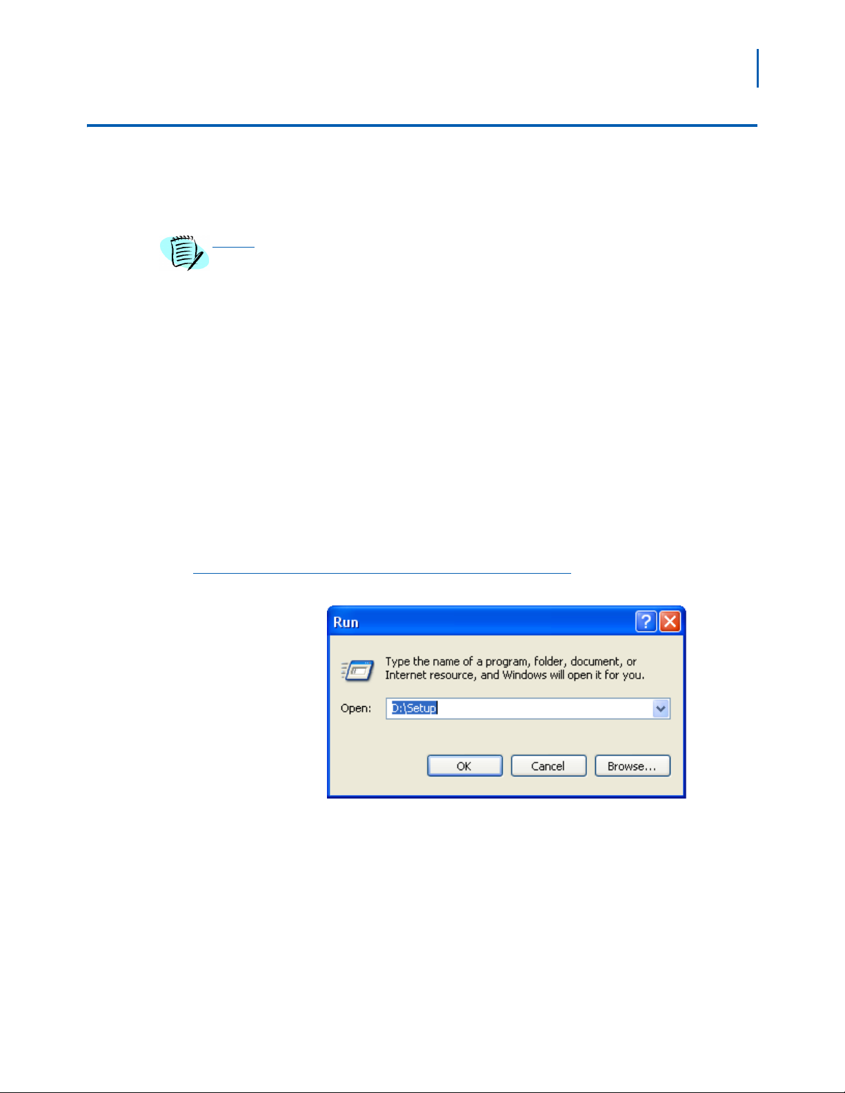
Step 3 Click the Windows Start button and select Run.... from the pop-up menu.
The Run (Figure 2-1) displays.
Run
Step 4 Type D:\Setup in the Open text box (as shown in Figure 2-1) and click
the OK butt
on. The Installation Manager R25 - InstallShield Wizard
Welcome displays (Figure 2-2).
MA4000 Installation Manager User Guide - Revision 7
Page 22
2-4 Getting Started
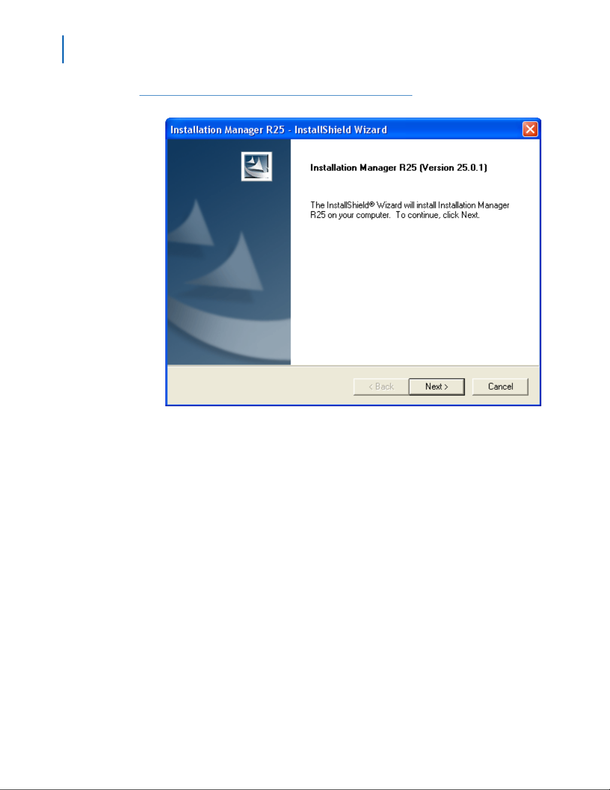
Figure 2-2
Installation Manager R25 - InstallShield Wizard Welcome
Step 5 Follow the prompts in the Setup program to accept the software licensing
agreement, to enter your customer information, and to select the setup
type. The Setup program copies the required files to your hard drive.
Step 6 The Installation Manager R25 - InstallShield Wizard Complete displays
(Figure 2-3) after the Setup program has finished copying files to your
hard disk.
MA4000 Installation Manager User Guide - Revision 7
Page 23

Getting Started 2-5
Figure 2-3
Installation Manager R25 - InstallShield Wizard Complete
Step 7 Click the Finish button. The Installation Manager R25 - InstallShield
Install Feature(s) displays (Figure 2-4).
MA4000 Installation Manager User Guide - Revision 7
Page 24
2-6 Getting Started
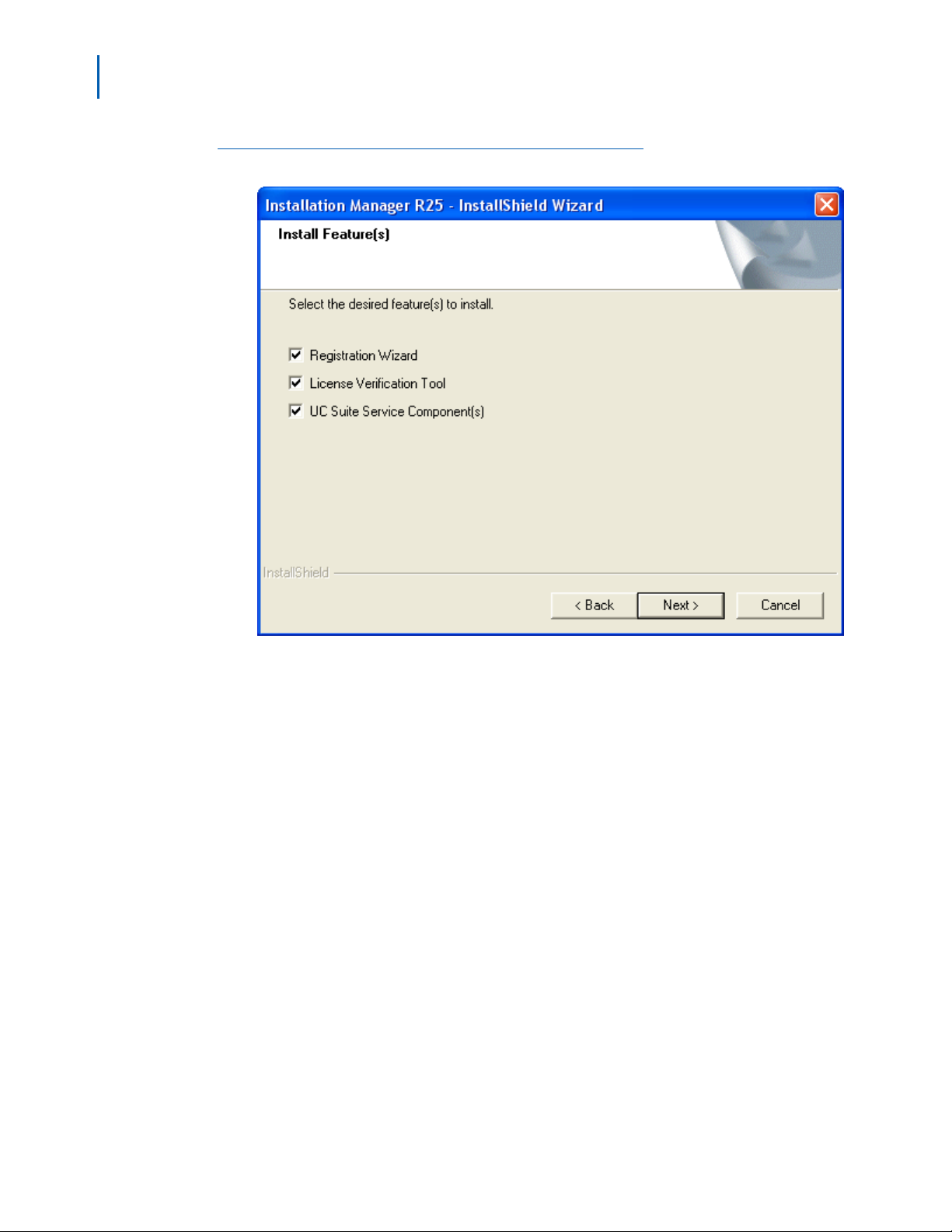
Figure 2-4
Installation Manager R25 - InstallShield Install Feature(s)
Step 8 Select the appropriate check box to install the desired feature. After
MA4000 Installation Manager finishes installing each selected feature,
you can now run the MA4000 Installation Manager program.
MA4000 Installation Manager User Guide - Revision 7
Page 25

Getting Started 2-7
Initializing the Flash Card and Installing the System Software (SV7000 MPS Only)
The following procedure contains a step which can result in the loss of existing data
on your computer if performed improperly. This step is indicated with a Caution
CAUTION
symbol. If you are unsure whether you understand the step completely, contact the
NEC Technical Assistance Center (NTAC) before proceeding.
Introduction and Requirements
The SV7000 MPS ships with an empty ATA flash card. Before you start
the server, you must initialize the card and load it with system software
the server requires to run. Then, you use the flash card to transfer the
system software to the server itself.
This procedure requires the system software CD (supplied with your
system) and a laptop PC with a PCMICIA card slot. Your laptop PC must
be configured to boot from the CD drive.
NOTE
To configure your PC to boot from a CD, you may need to change the boot drive
order in your computer’s BIOS. You can usually display the BIOS settings screen by
pressing a specific key during the boot sequence.
For specific information on configuring your laptop to boot from a CD, consult your
computer’s documentation.
The SV7000 MPS runs the Linux operating system. When you boot from
the supplied system software CD, your laptop will also be running Linux.
You can then use Linux to initialize the flash card and transfer the MPS
system software to it.
You should also be familiar with the NEC Maintenance and
Administration Terminal (MAT) application. For specific information on
using the MAT, consult its online help documentation.
Major Tasks
The following lists the major tasks you will complete when you initialize
the flash card and load system software on the MPS:
• Boot your laptop from a CD contai
• Use the Linux command line interface to format the flash card.
• Copy the MPS operating system files to the flash card.
• Insert the flash card in the MPS server.
• Connect your laptop directly to the MPS.
• Copy the system software from the flash card to the MPS.
• Specify the MPS’ new T
CP/IP network settings.
• Restart the MPS using the new network settings.
ning the Linux operating system.
MA4000 Installation Manager User Guide - Revision 7
Page 26

2-8 Getting Started
Step-by-Step Procedure
To initialize the flash card, install it in the server, and load the MPS
system software do the following:
Step 1 Insert the MPS system software CD into your computer, then reboot.
—Linux status messages display, followed by a video mode prompt.
Step 2 Press Space to accept the default video mode. A keyboard selection
prompt displays.
Step 3 Press Enter to accept the default keyboard configuration. A Linux
command prompt displays.
Step 4 Enter root as the login ID, then enter xxxx as the password (the
password entry will not display on the screen).
IMPORTANT
IMPORTANT
—The Linux command prompt changes to #, in
dicating you are logged in
as a root user.
You must enter these values exactly as they are shown here because the Linux
operating system, unlike Windows, is case-sensitive. That is, root and Root are not
identical.
Be careful to enter the values in the rema
including spaces.
Step 5 Type the following at the command prompt, then press Enter:
ining steps exactly as they are shown,
/bin/dmesg | grep hd
—A list of configured devices on your PC displa
ys, designated hda, hdb,
hdc, etc.
Step 6 Use the list of displayed devices to locate your laptop’s hard drive and
CD-ROM drive. Write down their designations (hda, hdc, etc.) so you will
remember them.
It is critical you correctly identify your CD-ROM and internal hard drive from the list of
displayed devices. You will need the correct designation in later steps to select which
device will be formatted.
Linux identifies drives on you
with a and continuing alphabetically. Commonly, the internal hard drive is hda and
the internal CD-ROM is hdc. However, your configuration may be different. You can
identify your drives using the information displayed after the previous step. For
example, here is a possible drive listing:
r computer with the hd designation, plus a letter starting
hda: HTS54809349, ATA disk drive
hdc: Samsung CDRW-DVD, ATAPI CD-ROM drive
hda: HTS54809349, 76319MB w/ 7877kB cache
hdc: ATAPI 24X DVD-ROM CD-RW drive, 2048kB cache
hda: hda1, hda2
This listing shows the internal 80MB hard drive as hd
CD-ROM drive as hdc.
MA4000 Installation Manager User Guide - Revision 7
a. You can easily identify the
Page 27

Getting Started 2-9
Step 7 Type the following at the command prompt, the press Enter:
mount /dev/hdc /mnt/cdrom
Replace hdc
in the command, if necessary, with the designation your
laptop uses for the internal CD-ROM device.
CAUTION
—Linux mounts the CD-ROM and infor
Step 8 Type the following at the command prompt, then press Enter:
ms you the device is read-only.
/mnt/cdrom/MKINIT
After a few moments, the MKINIT finish me
Step 9 Insert the flash card in your laptop’s PCMCIA card slot.
ssage displays.
—Linux reads the card and displays its size and drive designation (hde,
You will need this drive designation in Step 11.
etc.).
Step 10 Press Enter to return to the command prompt (#).
This next step will destroy any existing data on the specified device. Be certain you
have not entered the designation for your laptop’s hard drive when typing this
command.
Step 11
Type the following at the command prompt, then press Enter:
MK_FLASH hde
Replace hde
in the above command, if necessary, with the drive
designation your laptop displayed for the flash drive after you inserted
the card.
—You can ignore the Driv
—The writ
initialization completes. This process may take 20-30 minutes.
Step 12 Remove the flash card from your laptop.
—You can ignore the resulting error messages.
Step 13 Type the following at the command prompt, the press Enter:
exit
Step 14 Remove the MPS system software CD from your laptop.
Step 15 Reboot your laptop in the normal manner.
—After it reboots, it should be running the Windows operating system.
Step 16 Be sure the MPS is OFF, then insert the flash card in the appropriate slot.
Step 17 Turn the MPS ON.
MA4000 Installation Manager User Guide - Revision 7
eReady and DriveStatus error messages.
e finish status message displays when the flash card
Page 28

2-10 Getting Started
Step 18 Connect an ethernet cable between your laptop and the Ether1 jack on
the front of the MPS.
—You must use a crossover Ethernet
cable, not the more common
straight-through type.
Step 19 On your laptop, open the Network (or Network Connections) control
panel.
Step 20 Change your laptop’s network settings to the following:
IP Address: 192.168.0.5
Subnet Mask: 255.255.255.0
Default Gateway: 192.168.0.254
Step 21 Close the network control panel to save the new settings.
Step 22 Launch the PC Pro by doing one of the following:
—Open Installation Manager, then select PCPro... fr
—Locate the PCPro application on your
hard drive (if previously
om the Tools menu.
installed) and launch it.
Step 23 Log on to the MPS using its default IP (192.168.0.1), leaving the user
and password fields blank.
Step 24 Enter the ADTM command in the PCPro to display the default switch
configurations.
Step 25 Change the MPS’ IP address, subnet mask, and default gateway
address to the appropriate values for your network.
NOTE
Step 26 Click Apply.
Even though the values appear to revert to their default values, they have in fact
been changed. This is because although you have changed their value in the MPS’s
memory, they have not yet been stored to the flash card.
Step 27 Enter the SINZ command in the MAT, then select System Initialize
(Reboot).
Step 28 Click Execute. A confirmation dialog displays.
Step 29 Click Yes. The MPS reboots.
—During this time the AC
T light flashes GREEN and the Load light is
RED.
—The MPS is not ready until the ACT light remai
Step 30 Change your laptop’s TCP/IP network settings back to their original
ns solid GREEN.
values for use on your network.
MA4000 Installation Manager User Guide - Revision 7
Page 29
3
Graphical User Interface
This chapter provides an overview of the components of the MA4000
Installation Manager software.
The following topics are included in this chapter:
Chapter Topics • General Graphical User Interface Features
• Startup Dialog
• Pull-Down Menus
• Primary Sections
3-1
General Graphical User Interface Features
Data Navigator
The Data Navigator control allows you to easily go from item to item in a
list. There are buttons allowing you to go to the beginning and the end
of the list using a single button click.
The Data Navigator always displays information in the form [last
selected row] of [total rows] (see Figure 3-1).
Figure 3-1
Data Navigator Single Select example
MA4000 Installation Manager User Guide - Revision 7
Page 30
3-2 Graphical User Interface
If multiple rows are selected the display will be listed in the form [last
selected row] of [total rows] (see Figure 3-2).
Figure 3-2
Data Navigator Multi Select example
Example: If the list is displaying Row #1 at the top of the list, and the
user has made the selections from top to bottom, the last row
selected would have been Row #12.
MA4000 Installation Manager User Guide - Revision 7
Page 31

Graphical User Interface 3-3
Selecting
All list boxes will support the ability to multi-select items. There are two
ways to multi-select items:
Step To select a range of rows that are consecutive:
—Select the first item in the range
—Hold the Shif
between will be selected. In Figure 3-3, the fourth item in the
then the seventh item were selected while holding the Shif
items between were selected.
t key and select the last item in the list. All items in
list and
t key. All
Figure 3-3
Figure 3-4
List Box Contiguous Select example
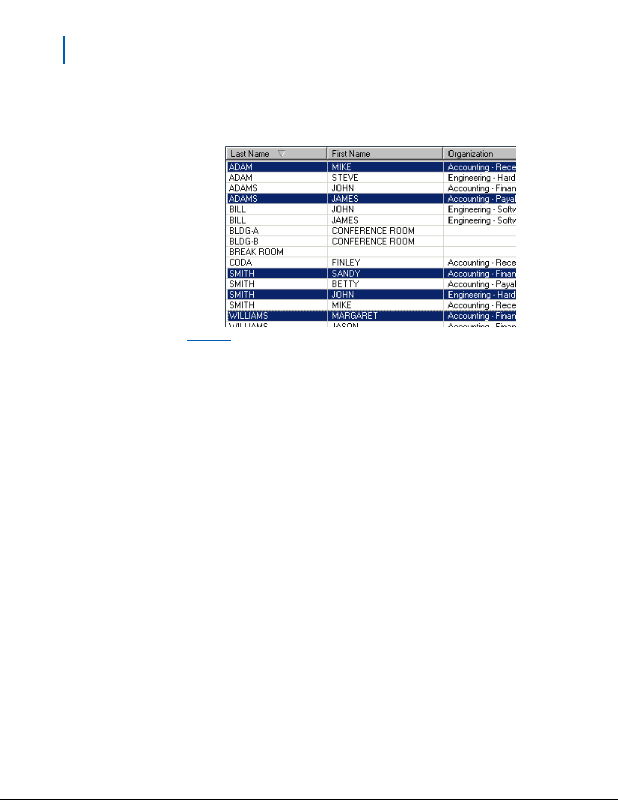
Step Another method is to choose multiple items by selecting rows while
holding the Control key. This allows the selection of non-consecutive
items. In Figure 3-4, the fourth, sixth, and eighth items were selected.
List Box Multi-Select example
If you choose an operation, such as clicking the Edit button, you will be
editing all the selected records in a smaller list. Figure 3-5 displays how
this would appear if you chose four items from the list, and then clicked
the Edit button.
MA4000 Installation Manager User Guide - Revision 7
Page 32

3-4 Graphical User Interface
Figure 3-5
Edit Multiple Records example
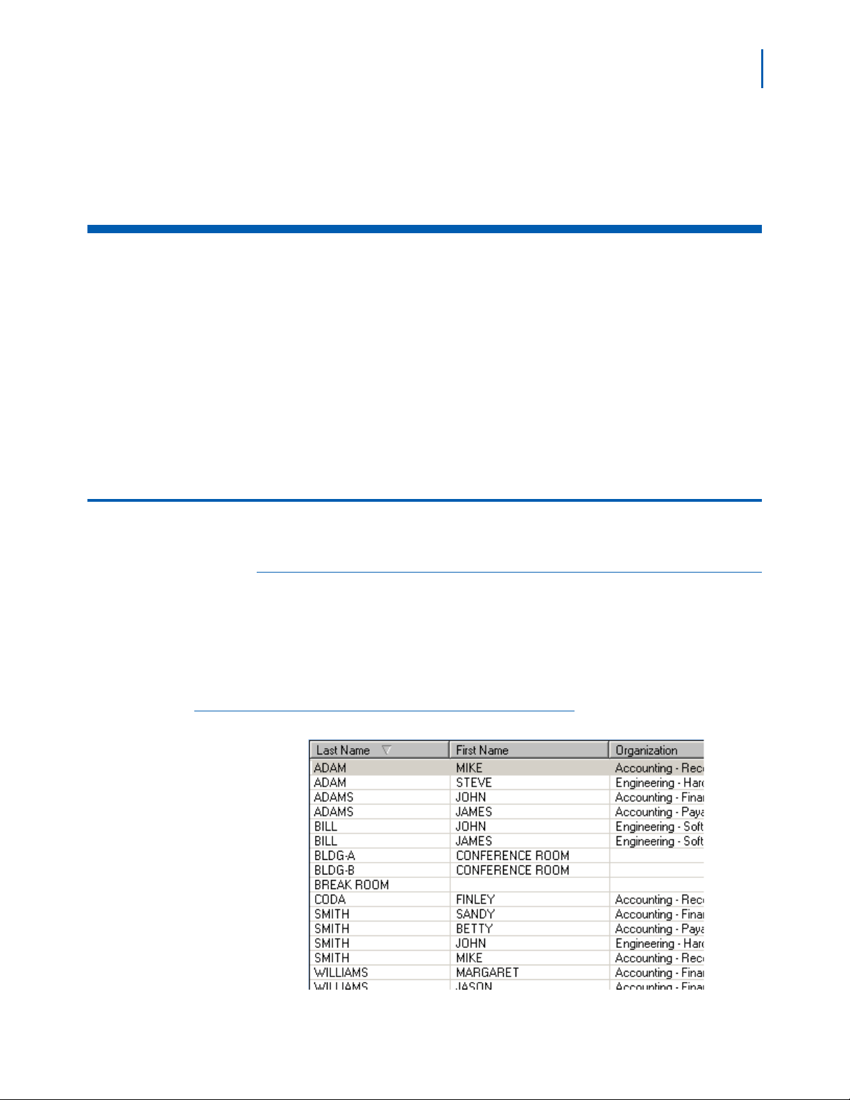
List Box Sorting
All lists will have the ability to sort. Clicking on the title bar of a column
causes the list to be sorted alphabetically by that column. A second click
will reverse the sort order. Clicking in a different column will cause the
list to be sorted by that column. There will be an arrow in the column
currently being sorted. Figure 3-6 indicates the Status field is being
sorted alphabetically. Another click on the title would cause the sort to
reverse and the arrow would be pointing UP instead of DOWN.
Figure 3-6
List Box Sorting example
MA4000 Installation Manager User Guide - Revision 7
Page 33

Startup Dialog
Graphical User Interface 3-5
MA4000 Installation Manager projects are not comprised of a single file
like a spreadsheet or document. Instead, the project is consists of
information contained in a database. To support this, your are given the
Installation Manager Startup (Figure 3-7) to perform basic management
on MA4000 Installation Manager projects.
Figure 3-7
Installation Manager Startup
• Projects tab
The projects listed here were created using t
• Templates tab
T
he projects listed under this tab were created using a template
based on criteria other than the default template.
You have the ability to have multiple instances of MA4000 Installation
Manager
project that is not already opened.
Once the user opens a project Figure 3-7 disappears. To open another
instance of MA4000 Installation Manager, you must return to the
shortcut used to launch MA4000 Installation Manager. The MA4000
Installation Manager installation will place a shortcut on the Windows
Start Menu.
MA4000 Installation Manager User Guide - Revision 7
running. However, each instance will only be allowed to edit a
he default template.
Page 34

3-6 Graphical User Interface
Projects Tab
Figure 3-8
Figure 3-9
Projects Tab
New button
You will have several choices to make. Some of the most powerful
features of MA4000 Installation Manager is the ability to re-use previous
data. When a new project is defined, it can be defined from an existing
project so you do not have to start with an empty project. Clicking the
New button displays the Welcome to the Create Project Wizard (Figure
3-9).
Welcome to the Create Project Wizard
MA4000 Installation Manager User Guide - Revision 7
Page 35

Graphical User Interface 3-7
Create Project Wizard
Step 1 The Welcome to the Create Project Wizard greets you and informs you
that the wizard will be guiding you through the
a new project. The panel also warns you that some basic information will
be needed to complete the wizard. Click the Next button to continue. The
Create Project Wizard - Project Name and Type dialog box (Figure 3-10,
Figure 3-11, Figure 3-12, Figure 3-13 or Figure 3-14) displays.
steps necessary to create
Figure 3-10
Create Project Wizard - Project Name and Type - NEAX IPX and NEAX IPX DM
MA4000 Installation Manager User Guide - Revision 7
Page 36

3-8 Graphical User Interface
Figure 3-11
Create Project Wizard - Project Name and Type - NEAX IPX UMG
MA4000 Installation Manager User Guide - Revision 7
Page 37

Graphical User Interface 3-9
Figure 3-12
Create Project Wizard - Project Name and Type - UNVERGE IPX
\
MA4000 Installation Manager User Guide - Revision 7
Page 38

3-10 Graphical User Interface
Figure 3-13
Create Project Wizard - Project Name and Type - UNIVERGE SV7000
MA4000 Installation Manager User Guide - Revision 7
Page 39

Graphical User Interface 3-11
Figure 3-14
Create Project Wizard -Project Name and Type - UNIVERGE SV8500
NOTE
Step 2 The Create Project Wizard - Project Name and Type dialog box allows
you to enter a name for the project.
—Enter the project name in the Project Name fie
ld. The name must be
unique. There must not be any other projects using this name.
—Select the system type from the Syst
em Type drop-down menu.
• Business System
• Hospitality System
—Select the system type from the Hardware T
ype drop-down menu.
• NEAX IPX
• NEAX IPX DM
• NEAX IPX UMG
• UNIVERGE IPX
• UNIVERGE SV7000
• UNIVERGE SV8500
—Select the physical chassis count from the Phy
sical Chassis Count
drop-down menu.
• NEAX IPX / NEAX IPX DM / UNIVERGE IPX: 1 to 16
• UNIVERGE SV7000 / UNVERGE SV8500: 0, 1, 2, 3, and 4
Select the 6U Physical Chassis check box if your system uses a 6U-size physical
chassis. (Not available on NEAX IPX, NEAX IPX DM, or UNIVERGE SV8500)
MA4000 Installation Manager User Guide - Revision 7
Page 40

3-12 Graphical User Interface
• NEAX IPX UMG: None
—Select the maximum chassis count from the V
irtual Chassis Count
drop-down menu.
• NEAX IPX / NEAX IPX DM / UNIVERGE IPX: 0, 1, 2, and 3.
• NEAX IPX UMG: None
—Select the maximum system capacity from the Syst
em Maximum
Capacity drop-down menu.
• NEAX IPX / NEAX IPX DM / NEAX IPX UMG / and
UNIVERGE IPX: None
• UNIVERGE SV7000: 300, 750, 1000, 1500, 2000, 2500, 3000,
3500, 4000, 4500, 5000, 5500, and 6000
• UNVERGE SV8500: 384, 768, 1152, 1536, 1920, 2304, 2688, 3072,
3456, 3840, 4224, 4608, 4992, 5376, 5760, and 6144
—Select the Use Pha
se Installation check box to enable the phased
installation.
• All Systems Types: Available.
Figure 3-15
Click the Next bu
Create Project Wizard - Project Category and Notes
tton to proceed. Figure 3-15 displays.
Step 3 The Create Project Wizard - Project Category and Notes allows you to
provide additional information about the project, and permits you to
orizing the project.
categ
Step 4 Click the Next button to proceed. Figure 3-16 displays.
MA4000 Installation Manager User Guide - Revision 7
Page 41

Graphical User Interface 3-13
Figure 3-16
Create Project Wizard - Customer Locations
Step 5 The Create Project Wizard - Customer Locations is similar to the
Customer Organization (Step 6). It allows you to specify locations for all
telephone so they can be accurately delivered to the necessary
locations.
This information is also very important when cabling personnel
have to complete the end to end connectivity from the telephone to the
Voice Server system.
Click the Next bu
tton to continue. Figure 3-17 displays.
MA4000 Installation Manager User Guide - Revision 7
Page 42

3-14 Graphical User Interface
Figure 3-17
Create Project Wizard - Customer Organization
Step 6 The Create Project Wizard - Customer Organization allows you to name
the levels in a customer's organization. It is very similar to naming the
ls in a company's organizational chart. These levels are used heavily
leve
to sort out relevant data. This is particularly powerful when there are
large numbers of phones/employees and the user is trying to set up hunt
groups based on a department within the company.
Click the Next bu
tton to continue. Figure 3-18 displays.
MA4000 Installation Manager User Guide - Revision 7
Page 43

Graphical User Interface 3-15
Figure 3-18
Create Project Wizard - Voice Mail
Step 7 The Create Project Wizard - Voice Mail allows you to choose from any
supported voice mail system. Current selections include:
<None>
<Other Voice Mail>
NEAX Mail AD-64 -
A voice messaging system providing ViewMail®,
ViewMail for Microsoft® Messaging, ViewMail for Lotus® Notes®,
ViewMail for GroupWise®, and ViewCall® Plus (Windows 2003-based).
UM8500 Exchange Message Store -
A voice messaging offering
powerful productivity features such as VideoMail, Find Me Follow Me and
Desktop Call Control (IP-based).
UM8500 SQL Message Store -
A voice messaging offering powerful
productivity features such as VideoMail, Find Me Follow Me and Desktop
Call Control (IP-based).
UNIVERGE UM4730 - A vo
ice messaging system providing
TeLANophy® modules, ViewMail®, ViewMail for Microsoft® Messaging
and ViewCall® Plus (PC-based/Linux OS).
Click the Next bu
tton to proceed. Figure 3-19 displays.
MA4000 Installation Manager User Guide - Revision 7
Page 44

3-16 Graphical User Interface
Figure 3-19
Create Project Wizard - Customer Contact Information
Step 8 The Create Project Wizard - Customer Contact Information allows you to
enter details about the customer that is custom to this new project.
Click the Next bu
tton. Figure 3-20 displays.
MA4000 Installation Manager User Guide - Revision 7
Page 45

Graphical User Interface 3-17
Figure 3-20
Completing the Create Project Wizard
Step 9 The Completing the Create Project Wizard is the last panel you will
encounter as part of the Create Project Wizard.
Click the Finish
button to end the Wizard and return to Figure 3-7.
MA4000 Installation Manager User Guide - Revision 7
Page 46

3-18 Graphical User Interface
•Import button
Step 1 Click the Import button as shown in Figure 3-21.
Figure 3-21
Projects Tab
Figure 3-22 displays.
MA4000 Installation Manager User Guide - Revision 7
Page 47

Graphical User Interface 3-19
Figure 3-22
Import Project
Figure 3-23
Step 2 Select an existing project and click the Open button. The selected
project now appears in the Select Project: section of the Installation
Manager Startup.
• Delete button
Step 1 Select a project from the list located in the Installation Manager Startup
(Figure 3-7).
Step 2 Click the Delete button. Figure 3-23 will display.
Delete Project Confirmation
MA4000 Installation Manager User Guide - Revision 7
Page 48

3-20 Graphical User Interface
• Delete All button
Step Click the Delete All button. Figure 3-24 will display.
Figure 3-24
WARNING
Delete All Projects Confirmation
•
Refresh button
Clicking the Yes button deletes a project entirely and removes the project from the
database. The project cannot be recovered.
The Refresh but
ton performs a new search in the database to
discover all projects defined on the current personal computer. The list
will be updated with the latest information.
•OK butt
on
The OK button will open the selected project and make it available for
edit
ing.
•Cancel butt
on
The Cancel button is used to abort opening any project. You will need
to
re-launch the application using MA4000 Installation Manager
shortcut.
MA4000 Installation Manager User Guide - Revision 7
Page 49

Templ ates Tab
Graphical User Interface 3-21
Figure 3-25
Temp l ates Ta b
•New button
Highlighting a template listed in the Select Template: section, and
cl
icking the New button, will show the same Figure 3-9 through Figure
3-20 dialog boxes as the Project Tab displayed. This option provides
you the opportunity to modify the imported
template to meet your
specific requirements.
•Import bu
Step 1 Click the Import button. Figure 3-26 displays.
tton
MA4000 Installation Manager User Guide - Revision 7
Page 50

3-22 Graphical User Interface
Figure 3-26
Import Template
Figure 3-27
Step 2 Select the template to import from those templates listed, and click the
Open button.
• Delete butt
Step 1 Select a template from the list located in the Installation Manager Startup
on
(Figure 3-7).
Step 2 Click the Delete button. Figure 3-27 will display.
Delete Project Confirmation
MA4000 Installation Manager User Guide - Revision 7
Page 51

Graphical User Interface 3-23
• Delete All button
Step Click the Delete All button. Figure 3-28 will display.
Figure 3-28
WARNING
Delete All Projects Confirmation
•
Refresh button
Clicking the Yes button deletes a template entirely and removes the template from
the database. The project cannot be recovered.
The Refresh but
ton performs a new search in the database to
discover all templates defined on the current personal computer. The
list will be updated with the latest information.
•OK butt
on
The OK b
utton will open the template project and make it available
for editing.
•Cancel butt
on
The Ca
ncel button is used to abort opening any template. You will
need to re-launch the application using MA4000 Installation Manager
shortcut.
MA4000 Installation Manager User Guide - Revision 7
Page 52

3-24 Graphical User Interface
Pull-Down Menus
File Menu
The File pull-down menu contains these file functions:
reate Project...
• C
• Open Project..
• Save As
— Pro
— Templ
•Exit
ject...
.
ate...
Figure 3-29
Edit Menu
The Edit pull-down menu (Figure 3-29) contains the common functions
typically found in stand-alone applications.
Edit Menu
Cut (Ctrl+X)
Step 1 Select an item (this could be the context of a text box, or it could be
multiple items in a list).
Step 2 After a selection is made, press the Ctrl and X keys to place the contents
in the Windows Clipboard.
Step 3 You can now paste the contents to another location, such as another
windows application, or to another location within MA4000 Installation
Manager.
MA4000 Installation Manager User Guide - Revision 7
Page 53

Graphical User Interface 3-25
Copy (Ctrl+C)
Step 1 Select an item (this could be the context of a text box, or it could be
multiple items in a list).
Step 2 After a selection is made, press the Ctrl and C keys. A copy of the
selected item(s) is placed on the Windows Clipboard.
Step 3 You can now paste the contents to another location, such as another
windows application, or to another location within MA4000 Installation
Manager. See Paste (Ctrl-V)
Paste (Ctrl-V)
Step 1 Place the curser in the field or in the row below where the contents of the
Windows Clipboard is to be pasted.
Step 2 If an item is selected, then the past operation will replace the selected
item. In the case of a list box, the contents of the clipboard will be pasted
above the cursor location.
The contents of the clipboard must have the same number of columns as
e destination list box. If it does not have exactly the same number of
th
columns, the operation will not occur.
Figure 3-30
WARNING
NOTE
Tools Menu
The Tools pull-down menu (Figure 3-30) contains the Flash Card
Wizard, Registration Wizard, PCPro, License Verification Tool,
Clipboard, and Network Manager functions.
Tools Menu
Flash Card Wizard ...
The Flash Card Wizard does not work on MPS due to MPS being Linux-based. See
Registration Wizard ... for procedure to upgrade the system.
UNIVERGE SV8500 is not supported by the Flash Card Wizard function.
The Flash Card Wizard option provides the tools to:
• Format and write new program files to a new flash card
• Upgrade the program files by reading program files to the personal
computer and modi
fying the files using Explorer to write to the flash
MA4000 Installation Manager User Guide - Revision 7
Page 54

3-26 Graphical User Interface
card, or backup data by reading data from the flash card to the
personal computer. See Figure 3-31.
To launch the Flash Card Wizard, do the following:
Step From Microsoft Desktop, select Start > Programs > Installation
Step From the Installation Manager Menu Bar, click Tools > Flash Card
Manager 24 > Flash Card Wizard.
OR
Wizard ....
Figure 3-31
FLCVTR Initial
IMPORTANT
The flash card installation needs to be installed using the MPS System CD-ROM.
• If the Initial Installation Execute button is clicked, Figure 3-32
displays.
MA4000 Installation Manager User Guide - Revision 7
Page 55

Graphical User Interface 3-27
Figure 3-32
FLCVTR Initial Installation Execute
Step 1 Insert an unformatted flash card into an available PCMCIA slot. Ensure
you insert a flash card prior to launching the FLCVTR program in order to
display the PC’s PCMCIA slot for the Flash Card field.
Step 2 Click the Browse button to locate the file containing the program to be
written to the flash card.
If defining the partition size is necessary, select the appropriate size from the pulldown menu located in the Partition Size (MB) field. Normally, the Partition Size
NOTE
MA4000 Installation Manager User Guide - Revision 7
(MB) field is not visible, choose the Option menu item and select the PartitionSize
Select option to make the field visible.
Step 3
Step 4 Click the Set button to write the program to the flash card.
Step 5 After pressing the Set button, Figure 3-33 displays.
Select the PCMCIA slot for the flash card.
Page 56

3-28 Graphical User Interface
Figure 3-33
Setting INITDATA
Step 6 Enter the IP Address, Subnet Mask and Gateway of the SV7000, then
click the Set button.
NOTE
This option only applied to the SV7000, and is not available for a NEAX 2400 IPX.
MA4000 Installation Manager User Guide - Revision 7
Page 57

Graphical User Interface 3-29
• If the Program Upgrade Execute button is clicked, Figure 3-34
displays.
Figure 3-34
FLCVTR Program Upgrade Execute
Step 1 Insert the flash card containing the program files into an available
PCMCIA slot.
Step 2 In the Drive field, choose the drive containing the program files and the
location where the files are to be written.
If the Drive field is not visible, choose the Option menu item and select the Drive
Select option.
TIP
Step 3
Step 4 Click the Browse button to locate the folder or CD Drive where the
Select the PCMCIA slot for the flash card.
Program Files are located.
Step 5 Click the Set button to load the Program Files to the Flash Card.
MA4000 Installation Manager User Guide - Revision 7
Page 58

3-30 Graphical User Interface
•If the Data Backup Execute button is clicked, Figure 3-35 displays.
Figure 3-35
FLCVTR Data Backup Execute
TIP
Step 1 Insert the flash card containing the program files into an available
PCMCIA slot.
Step 2 In the Drive field, choose the drive containing the office data files and the
location where the files are to be written.
If the Drive field is not visible, choose the Option menu item and select the Drive
Select option.
Step 3
Step 4 Click the Browse button to locate the folder where the office data files
Select the PCMCIA slot for the flash card.
will be written.
Step 5 Click the Get button to write the office data files located on the flash card
to the location selected.
MA4000 Installation Manager User Guide - Revision 7
Page 59

NOTE
Graphical User Interface 3-31
Registration Wizard ...
The Registration Wizard screens that display for the UNIVERGE SV8500 system will
be different from the screens shown in the following example.
The Registration Wizard connects your system to the NEC
Registration Service and obtains your Activation Code. See Figure 3-36.
To launch the Registration Wizard, do the following:
Step From Microsoft Desktop, select Start > Programs > Installation
Manager R25 > Registration Wizard.
OR
Step From the Installation Manager Menu Bar, click Tools > Registration
Wizard ....
Figure 3-36
Welcome to the Registration Wizard
Step 1 Select the Next button to proceed. Figure 3-37 displays.
MA4000 Installation Manager User Guide - Revision 7
Page 60

3-32 Graphical User Interface
Figure 3-37
NEC Registration Wizard - We Want To Know About You
Step 2 Select the Next button to continue. Figure 3-38 displays.
MA4000 Installation Manager User Guide - Revision 7
Page 61

Graphical User Interface 3-33
Figure 3-38
NEC Registration Wizard - Site Information
Step 3 Enter the site information requested. Those fields denoted with an
asterisk require an entry.
Step 4 Click the Next button to continue. Figure 3-39 displays.
MA4000 Installation Manager User Guide - Revision 7
Page 62

3-34 Graphical User Interface
Figure 3-39
NEC Registration Wizard - Complete Your NEC Registration
Step 5 Click the Next button. Figure 3-40 displays.
MA4000 Installation Manager User Guide - Revision 7
Page 63

Graphical User Interface 3-35
Figure 3-40
NEC Registration Wizard - Select System to Activate
NOTE
Step 6 Select the appropriate system from the list provided.
—Direct
Connection to the System. Enter the communication port and
baud rate.
—IP Con
The IP address entered here will determine the system information that will display
when Get System Information is selected in Step 8.
nection to the System. Enter the IP address.
—Modem Connection to the System. Select the modem type, enter
the dialing number, and create, edit or retrieve a connection profile.
Click the Save Connection button to save the modem profile.
Step 7 Click the Next button. Figure 3-41 displays.
MA4000 Installation Manager User Guide - Revision 7
Page 64

3-36 Graphical User Interface
Figure 3-41
NEC Registration Wizard - Gather Security Codes from System - SV7000 Example
Step 8 Click Get System Information to connect your system and obtain/
update the hardware and software key codes, then click the Next.
Figure 3-42 displays for all systems except UNIVERGE SV8500.
For UNIVERGE SV8500, when Next is
clicked, the Choose Options to
Activate Your UNIVERGE SV8500 dialog displays providing options for
obtaining/uploading the needed SVI.zip file or for proceeding directly to
the UNIVERGE 8500 Activation Step.
—If you do not already have a SVI.zip file, use the O
btain SVI File steps
listed in Table 3-1 to retrieve the license file.
—If you have a SVI.zip file and want
to upload it to the UNIVERGE
SV8500, use the Upload SVI File steps listed in the same table.
—If you wish to skip the two options above and proceed directly to the
UNIVERGE SV850
0 Activation Step, use the Activate steps listed in
the table.
MA4000 Installation Manager User Guide - Revision 7
Page 65

Table 3-1 Options to Activate the UNIVERGE SV8500
Obtain SVI File Upload SVI File Activate
Graphical User Interface 3-37
Step 1. Login to the License
Management Server
(LMS) and download the
SVI.zip file.
Step 2. Load the SVI.zip file to the
UNIVERGE SV8500.
Step 3. Obtain the Key Code File
from the UNIVERGE
SV8500.
Step 4. Upload the Key Code File
to the LMS and obtain the
Activation Code from the
LMS (either by web
display or e-mail).
Step 5. Register the Activation
Code to the UNIVERGE
SV8500.
Step 1. Load the SVI.zip file to the
UNIVERGE SV8500.
Step 2. Obtain the Key Code File
from the UNIVERGE
SV8500.
Step 3. Upload the Key Code File
to the LMS and obtain the
Activation Code from the
LMS (either by web
display or e-mail).
Step 4. Register the Activation
Code to the UNIVERGE
SV8500.
Step 1. Upload the Key Code File
to the LMS and obtain the
Activation Code from the
LMS (either by web
display or e-mail).
Step 2. Register the Activation
Code to the UNIVERGE
SV8500.
MA4000 Installation Manager User Guide - Revision 7
Page 66

3-38 Graphical User Interface
Figure 3-42
NEC Registration Wizard - Registration Information
Step 9 In the Modem Configuration Section, enter or select the correct
information into the Modem Name and Registration Server Dialing
Number fields.
Step 10 Click Connect to NEC Registration Server and obtain the Activation
Code.
—The modem defined in Step 9 calls into the server
Activation Code, or you can select the By
TCP-IP option button to
and retrieves the
connect using that method.
—The activation code will display in Act
ivation Code field after
successful registration with the NEC Registration Service.
Step 11 Select the Next button. Figure 3-43 displays.
MA4000 Installation Manager User Guide - Revision 7
Page 67

Graphical User Interface 3-39
Figure 3-43
NEC Registration Wizard - Activate Your System
Step 12 To activate your system, click the Next button. Figure 3-44 displays.
MA4000 Installation Manager User Guide - Revision 7
Page 68

3-40 Graphical User Interface
Figure 3-44
NEC Registration Wizard - System Activation
NOTE
Step 13 Select the Send Activation License button to activate your system.
Step 14 Select the Next button to proceed. Figure 3-45 displays.
If the Activation License field is empty, you can either go back and connect to the
NEC Registration Server or temporarily activate your system with the Unlock button.
MA4000 Installation Manager User Guide - Revision 7
Page 69

Graphical User Interface 3-41
Figure 3-45
NEC Registration Wizard - Congratulations
Step 15 Click the Finish button to exit the Registration Wizard.
PCPro ...
The PCPro provides centralized online HTML-based programming access,
allowing administraators to manage terminals, schedule maintenance
and firmware updates, and remotely make moves, additions, or
changes.
Experienced users who wish to use the PCPro to send commands
directly to the switch can launch it from within Installation Manager.
To launch the PCPro, do the following:
Step 1 Launch the Installation Manager. The Startup dialog displays.
Step 2 Select an existing project or create a new project. The Installation
Manager main screen displays.
Step 3 Select Tools > PCPro.... The PCPro launches and displays as a
separate application.
MA4000 Installation Manager User Guide - Revision 7
Page 70

3-42 Graphical User Interface
License Verification Tool ...
SV8500 does not support the License Verification Tool function.
NOTE
The License Verification Tool provides a brief summary of the primary
licenses that are available (and in use) on your SV7000 system.
This tool is for planning purposes only and should not be construed as any legal
definition of the number of licenses that a customer has purchased or is entitled.
NOTE
To launch the License Verification Tool, do the following:
Step From Microsoft Desktop, select Start > Programs > Installation
Step From the Installation Manager Menu Bar, click Tools > License
Manager R25 > License Verification Tool.
OR
Verification Tool ....
REFERENCE
Clipboard...
Installation Manager now provides experienced users with integrated
access to the MAT Clipboard application. You can use this tool to access
MAT commands and transfer information directly to the Voice Server or
work offline and upload all changes at once.
The Clipboard can save command data from the Voice Server as XML
(Extensible Markup Language) files. You can then edit the XML files
using Microsoft Excel and upload the modified data back to the Voice
Server. Many MAT commands are time-consuming when programmed
individually. Using the Clipboard to download and upload the command
data in a single operation can make many tasks more efficient. For
example:
• Create an off-line XML file containing a large number of new users,
configu
to the Voice Server.
• Transfer data from an old Voice Server to a new Voice Server by
downloading user data, edit
Voice Server.
For more complete information on using the Clipboard, refer to its user
documentation.
The Clipboard application (Figure 3-46) speeds system installations and
eliminates errors by importing data from one switch to a destination
switch.
red using the ASDT and AKYD commands, then upload the file
ing it off-line, then uploading it to the new
MA4000 Installation Manager User Guide - Revision 7
Page 71

Graphical User Interface 3-43
Clipboard has been enhanced to be able to perform batch downloads.
You have the ability to:
• Download data from the switch based on categories (for example,
Station Data, Trunk Data, Restricted Data, etc.)
• Add commands the data needs to be download to a list that would be
run as a batch
process.
• Save selected commands in user template files for future access.
Figure 3-46
This enhancement lessens the work
needed when downloading data for
the same set of commands.
To launch Clipboard, do the following:
Step From Microsoft Desktop, select Start > Programs > Installation
Manager R25 > Clipboard.
OR
Step From the Installation Manager Menu Bar, click Tools > Clipboard.
MAT Clipboard
Network Manager...
The Network Manager is used to manage existing networks while using
Installation Manager to install and manage new networks.
The Network Manager application is intended to enhance the capabilities
already present within Installation Manager, but it does not require
Installation Manager in order to perform its task. Network Manager can
function in a stand-alone mode and has the capability of integrating
nodes into the Fusion (FCCS) Network whether or not the connecting
node was originally programmed using the MAT, the Installation
Clipboard application, or Installation Manager.
Use of this software is normally conducted as follows:
Step 1 Install NCN PBX using Installation Manager (optional).
Step 2 Install LCN PBX using Installation Manager (optional).
Step 3 Create FCCS Network using Network Manager (optional).
Step 4 Insert LCN node into existing FCCS Network using Network Manager.
MA4000 Installation Manager User Guide - Revision 7
Page 72

3-44 Graphical User Interface
Help Menu
The Help pull-down menu is the place to go for assistance or
information.
Help Index …
The Help Index... option displays the HTML, context sensitive help for
the MA4000 Installation Manager application.
View Log File …
The View Log File... option lists the current MA4000 Installation
Manager log build information.
View User’s Guide ...
The View User’s Guide... option displays this MA4000 Installation
Manager User Guide as a PDF.
About MA4000 Installation Manager …
Figure 3-47
The About MA4000 Installation Manager... option displays the
application’s version and copyright information (Figure 3-47).
About MA4000 Installation Manager
MA4000 Installation Manager User Guide - Revision 7
Page 73

Primary Sections
Graphical User Interface 3-45
The buttons located along the left side of the graphical user interface in
the Main window (see Figure 3-48) contain the core functions of MA4000
Installation Manager. This is where you will view, manipulate, and
prepare the data to be sent to the system.
Figure 3-48
Primary Sections Tabs
When a button is selected, a tab view appears for each running
horizontally across the top (see Figure 4-2). This information is a logical
break down of the main button selected on the left.
The following chapters will describe in detail every button and its
purpose.
MA4000 Installation Manager User Guide - Revision 7
Page 74

3-46 Graphical User Interface
MA4000 Installation Manager User Guide - Revision 7
Page 75

4
Project Information
This chapter describes the MA4000 Installation Manager’s Project
Information section (Figure 4-1) tabs.
Chapter Topics • Primary Contact Tab
• Company Organization Tab
• Tasks Tab
• Phased Installation Tab
4-1
Figure 4-1
Project Information Tab
MA4000 Installation Manager User Guide - Revision 7
Page 76

4-2 Project Information
Primary Contact Tab
The Primary Contact tab (Figure 4-2) is used to provide contact
information for a single person who will be the central point of contact
for the entire installation. Nothing on this tab will be transferred to the
system. It is only provided to centralize the information for the
installation.
Figure 4-2
Project Information - Primary Contact Tab
Company field
Enter the primary contact’s company name.
Contact field
This is the name of the individual who is the primary contact for the
customer.
MA4000 Installation Manager User Guide - Revision 7
Page 77

Project Information 4-3
Title field
Enter the primary contact’s title.
Phone field
Enter the primary contact's primary phone number.
Ext field
Enter the extension, if any, of the primary contact.
Fax field
Enter the facsimile phone number for the contact.
E-Mail field
Enter the contact’s e-mail address.
Address field
Enter the primary contact person’s address. There are 3 boxes available
for entering the full address (i.e. street, P.O. Box, building number, mail
stop, etc.)
City field
Enter the city where the contact is located.
State field
Enter the state where the contact is located.
Zip field
Enter the zip code for the contact’s mailing address.
Country field
Enter the country where the contact is located.
Notes field
This is a free form text box allowing you to enter any information that
maybe useful. You might want to enter a secondary contact, cell phone
information, or other meaningful information. The field might also be a
convenient spot to place notes concerning dates/times/outcomes of
conversations.
MA4000 Installation Manager User Guide - Revision 7
Page 78

4-4 Project Information
Company Organization Tab
The Company Organization tab (Figure 4-3) provides you with set
fields allowing you to describe the company. This is usually information
on the company where the system is being installed.
Figure 4-3
Project Information - Company Organization Tab
Locations section
The Location section displays a tree view of the information representing
the placement of telephone stations. The tree view can be thought of as
an address of sorts. To locate where someone lives, the country, state,
zip, street, and street number must be known. In the same fashion, a
telephone station must be easily located. This section provides the
means to break the company down into various locations. Some thought
should be given for the logical break down of the locations where
telephone stations will be installed. This information might be different
MA4000 Installation Manager User Guide - Revision 7
Page 79

NOTE
Project Information 4-5
for each installation. In Figure 4-3, the locations are broken down by
Building then by Floor.
The maximum number of levels supported is five.
This information will be used in reports to help identifying locations for
all telephone stations.
• Edit button
Before the Edit button can f
unction, an entry in the Locations tree
view must be selected. After selecting an entry, click the Edit button.
Figure 4-4 displays. You must close this dialog before continuing with
any other tasks.
Figure 4-4
Edit Location
As shown, you are allowed to modify the entry selected.
MA4000 Installation Manager User Guide - Revision 7
Page 80

4-6 Project Information
• New button
The New
button will allow you to define a new location.
See Figure 4-5.
Figure 4-5
New Location
If the location already exists, you will receive an error message stating
the location exists. You will be given the opportunity to make a change
or cancel.
You have the option to add a new location and remain in the New
Location Dialog. You simply click the OK button and the new location is
added.
MA4000 Installation Manager User Guide - Revision 7
Page 81

Project Information 4-7
• Delete button
To use the Delete
button, you must first select a branch or a leaf
element of the tree. Clicking the Delete button will display the
Confirmation - Delete This Item (Figure 4-6). If the user clicks the
Yes b
utton, the node will be removed, and any of its children.
Figure 4-6
Figure 4-7
Confirmation - Delete This Item
Selecting the Yes button will remove the element selected, and all
components beneath it, but will not abort the operation.
• C
onfigure button
The C
onfigure button allows you to define the names of the levels
within the customers organization. Figure 4-7 displays the dialog used
to define the organization levels.
Edit Location Labels - General
MA4000 Installation Manager User Guide - Revision 7
Page 82

4-8 Project Information
Organization section
The Organization section allows you to define the company structure
from an organization point of view. You can break the company down
into departments, divisions, and groups. Its flexibility allows you to
break items down in the best way possible.
The bottom half of Figure 4-3 displays a tree view of a defined
organization. This tree view should closely follow the organization break
down in a company.
Figure 4-8
• Edit butt
on
To use the Edit but
ton, you must select a node in the tree view. When
Edit button is clicked, Figure 4-8 displays. You will be able to modify
the name of that node.
Edit Organization - General
If you change the Division name to a new Division name, that will
create another division.
MA4000 Installation Manager User Guide - Revision 7
Page 83

Project Information 4-9
• New button
The New
button is used to create a new entry into the company
organization. You can define a new Division using this dialog. See
Figure 4-9.
Figure 4-9
New Organization - General
• Delete button
You must select the element in the Organization tree view
the Delete button. Figure 4-10 displays.
Figure 4-10
Confirmation - Delete This Item
Selecting the Yes button will remove the element selected and all
components beneath it, but will not abort the operation.
MA4000 Installation Manager User Guide - Revision 7
, then click
Page 84

4-10 Project Information
• Configure button
The Co
nfigure button allows you to define the names of the locations
within the customer’s buildings. Figure 4-11 displays the fields used to
define the organization levels.
Figure 4-11
Edit Organization Labels - General
MA4000 Installation Manager User Guide - Revision 7
Page 85

Tasks Tab
Project Information 4-11
The Tasks tab (Figure 4-12) allows you to create a task list to manage
items that must be completed to have a successful installation. Each
row in the list box represents a task.
Figure 4-12
Project Information - Tasks Tab
MA4000 Installation Manager User Guide - Revision 7
Page 86

4-12 Project Information
•Edit button
In order to use the Ed
it button, a task must be selected. The Edit
button will allow you to modify a task. Figure 4-13 displays a task
being edited.
Figure 4-13
Edit Task
NOTE
Selecting the Browse button for the Begin Date, Due Date, or Complete Date fields
causes an Edit Date dialog box (Figure 4-14) to appear. Use this pop-up calendar to
select the appropriate date for each field.
MA4000 Installation Manager User Guide - Revision 7
Page 87

Project Information 4-13
Figure 4-14
Edit Date - General
MA4000 Installation Manager User Guide - Revision 7
Page 88

4-14 Project Information
•New button
The New
button will add the current information to the task list. Click
the New button, and Figure 4-15 displays.
Figure 4-15
New Task - General
Figure 4-16
Once a task has been added, the status selected (Open, Started,
Testing, or Closed), and the Begin, Due, and Complete dates
chosen, click the OK button to return to the Tasks Tab.
• Delete butt
The Delete
on
button removes the current task from the task list. See
Figure 4-16.
Confirm Delete - Delete The Current Selected Task(s)
MA4000 Installation Manager User Guide - Revision 7
Page 89

Phased Installation Tab
The Phased Installation tab is intended for advanced users only!
CAUTION
The Phased Installation tab (Figure 4-17) allows the Installation
Manager (IM) to add additional user station data, MG devices, and
Circuit Cards to an existing Voice Server database. The user can install
the Voice Server data in different phases. The user and circuit card
assignments can be assigned to different phases. The other basic data
(access code, numbering plan, etc.) are for Phase 1 only.
Phased installations are intended for larger installations or Voice Server
conversions projects that must be implemented in distinct stages over a
period of days or weeks. Phased installation differs from a standard
installation in the fact that during a phased installation Installation
Manager will synchronize with the Voice Server and reconcile any
problems before uploading new data to the Voice Server.
If you do not turn on the phase feature, all functions act as they did with
the previous version of Installation Manager.
Project Information 4-15
MA4000 Installation Manager User Guide - Revision 7
Page 90

4-16 Project Information
Figure 4-17
Project Information - Phased Installation Tab
MA4000 Installation Manager User Guide - Revision 7
Page 91

• Edit or New button
When the Edit or New
Project Information 4-17
button is clicked, Figure 4-18 displays.
Figure 4-18
Phased Installation - New or Edit Button
— Enter the appropriate information, as needed, in the Description
and Notes fields.
— After uploading the data, the corresponding phase will be marked
as Dat
e Committed. The check box can be cleared to resume the
same phase data upload again.
Once a phase is uploaded, Installation Manager marks the phase as committed and
enters the date that the phase was uploaded. Remember, this does not mean the
NOTE
MA4000 Installation Manager User Guide - Revision 7
phase data has been uploaded to the switch.
Page 92

4-18 Project Information
MA4000 Installation Manager User Guide - Revision 7
Page 93

5
Hardware Information
This chapter describes the MA4000 Installation Manager’s Hardware
Information section tabs (see Figure 5-1).
Chapter Topics • Options Tab
• Media Gateway and Circuit Cards
• Voice Mail Tab
• Security Tab
5-1
Figure 5-1
Hardware Information Tab
MA4000 Installation Manager User Guide - Revision 7
Page 94

5-2 Hardware Information
Options Tab
Use Figure 5-2 (Options Tab) to configure miscellaneous system options.
Figure 5-2
Hardware Information - Options Tab
Project Name field
This is the name of the project database. You can change the database
name, but is recommended it remain as the name of the database. This
field is used in many reports to identify the installation the data is
associated with.
System Type field
Valid choices are NEAX IPX, NEAX IPX DM, UNIVERGE IPX, UNIVERGE
SV7000, NEAX IPX UMG, and UNIVERGE SV8500.
MA4000 Installation Manager User Guide - Revision 7
Page 95

Hardware Information 5-3
Dual CPU check box
Select to identify when redundant SV8500 and SV7000 T10 processors
are used.
Dual Time Division check box
Select to identify when redundant SV7000 T10 processors are
multiplexing.
6 Unit (6U) Physical Chassis check box
NOTE
NOTE
• Checked - Indicates 6U Physical Chassis’s are to be used.
• Unchecked - Indicates 9U Physical Chassis’s are to be used
SV8500 does not support 6U chassis configuration.
System Options section
This section determines how the system will be programmed, and what
commands will be used. It is used in reporting and consists of:
• Fusion Fusion network to which your system will connect. The option is not
available on SV7000 MPS. Select one of the following:
—NCN - Network Control Node (F
— LCN - Local Control Node
— Standalone - NEAX IPX/IPX DM or UNIVERGE IPX only
• Fusion Point Co
If the system is to be an LCN in a Fusion Network, select an
appropri
information so the system can be configured to support these
features.
• Attendant
— Access to Attendant (Operator Call) - This
company’s operator. This number will be referenced in several
areas as a macro. It is used heavily in templates such as Call
Forwarding.
— Use Monitored Number as Attendant
• System Name field
This is the name of the system. Thi
internally to the system.
Use the Fusion drop-down menu to specify the type of
usion Network NCN)
(Fusion Network LCN)
de (LCN Only)
ate Fusion Point Code. It is useful to provide a technician this
is the number of the
s information will be assigned
MA4000 Installation Manager User Guide - Revision 7
Page 96

5-4 Hardware Information
• IP Phone Type field
Example: If there is no IP Phone support needed, you will not have the
Allows specification of the IP Phone support needed in MA4000
Installation Manager. This setting determines what options are made
available in other areas of MA4000 Installation Manager.
option of viewing IP Phone Models in the Phone Model List on
the User Edit Dialog.
The IP Phone Type options will consist of a combination of the
following:
TDM
Requires a PIR. Time Division Multiplex phones are NEC non-IP, circuit
card based Dterm or analog phones.
IP P-P
IP Peer-to-Peer phones are NEC IP phones not requiring circuit cards.
SIP
Session Initiated Protocol are NEC or other vendor IP phones which
conform to SIP standards.
•Name Display and Name Display Length fields
Specify in the Name Display and Length fields the default format for
users with phones having Name Display support.
Connect Type section
This section allows you to specify the communication interface used to
connect to the system.
• TCP/IP option
— Address - IP address of the SV7000 T10 or IPX
— Port - 60000
• Direct option (requires serial cable and is not used for SV7000)
— Comm Port - Serial COM port of the PC which the MA4000
Installation Manager is operating on.
— Baud Rate - Default value is 4800
MA4000 Installation Manager User Guide - Revision 7
Page 97

NOTE
Hardware Information 5-5
User ID and Password fields (optional)
The User ID and Password fields can be used if authentication is
required.
The following options can only be used after the software has been successfully
installed and the system is online.
Test button
Clicking the Test button performs a verification of the system
connection selected. If the test connection fails, Figure 5-3 displays.
Figure 5-3
NOTE
Test Connection - Login Failed
Setup IP... button
Clicking the Setup IP ... button allows the user to configure the active
and standby IP addresses, subnet mask, default gateway, speed, duplex
mode, and the ARP broadcasting period (no send, 30 sec., 60 sec., or
120 sec.), if applicable. The user identification and backup IP passwords
can also be activated. See Figure 5-4 (UNIVERGE SV8500 example),
Figure 5-5 (UNIVERGE SV7000, UNIVERGE IPX, NEAX IPX, and NEAX
IPX DM example), and Figure 5-5 (NEAX IPX UMG example).
If the Backup IP/Password Settings option is selected, Installation Manager will
back up the SV7000 after configuring the IP address and password.
For the IPX, the Backup IP/Password Setting is not available. Instead, there is a
Total PIMs (Physical +Virtual) field.
The IPX Installation Manager will automatically perform a System Backup and then
reset the Voice Server, after the IP address and password are configured.
MA4000 Installation Manager User Guide - Revision 7
Page 98

5-6 Hardware Information
Figure 5-4
Edit IP Configuration - UNIVERGE SV8500 Example
MA4000 Installation Manager User Guide - Revision 7
Page 99

Hardware Information 5-7
Figure 5-5
Edit IP Configuration - UNIVERGE SV7000 and IPX, NEAX IPX, and NEAX IPX DM Example
MA4000 Installation Manager User Guide - Revision 7
Page 100

5-8 Hardware Information
Figure 5-6
Edit IP Configuration - NEAX IPX UMG
MA4000 Installation Manager User Guide - Revision 7
 Loading...