

Page 1

User’s Guide
I-Select TS100
I-Select TW100
Page 2

Page 3

100
Proprietary Notice and Liability Disclaimer
The information disclosed in this document, including all designs and related materials, is the
valuable property of NEC Computers International and/or its licensors. NEC Computers
International and/or its licensors, as appropriate, reserve all patent, copyright and other
proprietary rights to this document, including all design, manufacturing, reproduction, use, and
sales rights thereto, except to the extent said rights are expressly granted to others.
The NEC Computers International product(s) discussed in this document are warranted in
accordance with the terms of the Warranty Statement accompanying each product. However,
actual performance of each product is dependent upon factors such as system configuration,
customer data, and operator control. Since implementation by customers of each product may
vary, the suitability of specific product configurations and applications must be determined by
the customer and is not warranted by NEC Computers International.
To allow for design and specification improvements, the information in this document is subject
to change at any time, without notice. Reproduction of this document or portions thereof without prior written approval of NEC Computers International is prohibited.
Trademar ks
Adobe, and Adobe Acrobat are registered trademarks of Adobe Systems, Incorporated.
Microsoft, Microsoft Windows, Windows NT, Windows 95, Windows 98, Windows 2000 and
Windows Storage Server 2003 are all registered trademarks of Microsoft Corporation.
MS-DOS is a registered trademark of Microsoft Corporation.
Intel and Pentium are registered trademarks of Intel Corporation.
All other product, brand, or trade names used in this publication are the trademarks or registered
trademarks of their respective trademark owners.
January 2005 - rev 0.0
Copyright 2005
NEC Computers International B.V.
Nieuweweg 279
6603 BN Wijchen
The Netherlands
All Rights Reserved
Page 4

Page 5

I-Select TS100 / I-Select TW100 User Guide - Table of Contents
iii
Table of Contents
Table of Contents _______________________________________________________ iii
Using This Guide __________________________________________________ vii
Text Conventions __________________________________________________ viii
Related Documents __________________________________________________ ix
Safety Notices _______________________________________________________x
Safety Notices for Users Outside of the U.S.A. and Canada ________________ xi
Care and Handling _________________________________________________ xii
System Overview ______________________________________________________ 1-1
Overview _________________________________________________________ 1-2
System Features ___________________________________________________ 1-3
System Chassis Features _____________________________________________ 1-4
Front View _____________________________________________________ 1-4
Rear View _____________________________________________________ 1-5
System Connectors ____________________________________________ 1-6
RJ45 Leds ___________________________________________________ 1-6
Expansion Board Slots _________________________________________ 1-6
Internal View ___________________________________________________ 1-7
Motherboard ____________________________________________________ 1-8
Standard Features _________________________________________________ 1-10
PCI Slots _____________________________________________________ 1-10
PCI -E x16 Slot ________________________________________________ 1-10
PCI -E x1 Slots _________________________________________________ 1-11
Peripheral Bays ________________________________________________ 1-11
Optional Features _________________________________________________ 1-12
DVD-ROM Drive ______________________________________________ 1-12
DVD-ROM CD-RW Combination Drive ____________________________ 1-13
DVD+R9 (DL) Drive ____________________________________________ 1-14
Intel Pro 1000 MT LAN Board ____________________________________ 1-15
PCI-E x1 Syskonnect LAN Board __________________________________ 1-15
S-ATA Hard Disk Drive _________________________________________ 1-16
SCSI Hard Disk Drive ___________________________________________ 1-16
S-ATA Hard Disk Drives Cage ____________________________________ 1-16
SCSI Hard Disk Drives Cage ______________________________________ 1-16
Video Board ___________________________________________________ 1-17
nVidia Quadro FX 540 PCI-E x16 Video Board _____________________ 1-17
nVidia Quadro NVS280 PCI-E x16 Video Board ____________________ 1-17
PCI Video Board _____________________________________________ 1-17
Sony AIT1 Tape Backup Unit _____________________________________ 1-18
Sony AIT2 Tape Backup Unit _____________________________________ 1-18
DAT72 Tape Backup Unit ________________________________________ 1-18
EXPRESSBUILDER CD-ROM ______________________________________ 1-19
What You Can Do With the EXPRESSBUILDER CD __________________ 1-19
Software End User License Agreement ______________________________ 1-19
Page 6

I-Select TS100 / I-Select TW100 User Guide - Table of Contents
iv
Setting Up Your System _________________________________________________ 2-1
Overview _________________________________________________________ 2-2
Selecting a Site ____________________________________________________ 2-3
Unpacking the System ______________________________________________ 2-4
Rack Installation Kit Assembly _______________________________________ 2-5
Static Precautions ________________________________________________ 2-6
Installing the Support Rails ________________________________________ 2-8
Attaching the Handles to the Rack Mounting Frame _____________________ 2-9
Installing the Rack Mounting Frame on the Server ______________________ 2-9
Installing the Server in the Rack Cabinet _____________________________ 2-11
Making Connections _______________________________________________ 2-12
Connecting the Power Cord _________________________________________ 2-12
Using the System _________________________________________________ 2-13
Powering On your System ________________________________________ 2-14
Powering Off your System ________________________________________ 2-15
Forcing a Power Shutdown _______________________________________ 2-15
Configuring Your System _______________________________________________ 3-1
Configuring Your System ____________________________________________ 3-2
BIOS Setup Utility _________________________________________________ 3-3
Using the BIOS Setup Utility _______________________________________ 3-3
BIOS Setup Configuration Settings __________________________________ 3-4
Standard CMOS Features Menu ____________________________________ 3-5
IDE Channel 0 Master/ 0 Slave/ 1 Master/ 1 Slave Submenu ____________ 3-5
Advanced BIOS Features Menu ____________________________________ 3-6
Integrated Peripherals Menu _______________________________________ 3-7
PnP PCI Configurations Menu _____________________________________ 3-10
PC Health Status Menu __________________________________________ 3-11
MB Intelligent Tweaker Menu _____________________________________ 3-12
Configuring MotherBoard Jumpers ___________________________________ 3-13
Upgrading Your System ________________________________________________ 4-1
General Information ________________________________________________ 4-2
Static Precautions __________________________________________________ 4-2
Equipment Log ____________________________________________________ 4-3
Tools Recommended for Upgrading Your System _________________________ 4-3
Preparing Your System for Upgrade ___________________________________ 4-3
Removing or Installing the Right Side Door _____________________________ 4-4
Removing the Right Side Door _____________________________________ 4-4
Replacing the Right Side Door _____________________________________ 4-5
Removing and Replacing the Front Panel _______________________________ 4-6
Removing the Front Panel _________________________________________ 4-6
Replacing the Front Panel _________________________________________ 4-6
Installing and Removing the Hard Disk Drive Cage _______________________ 4-7
Installing the Hard Disk Drive Cage _________________________________ 4-7
Removing the Hard Disk Drive Cage ________________________________ 4-8
Cabling the Hard Disk Drive Cage _____________________________________ 4-9
Cabling the SCSI Hard Disk Drive Cage ______________________________ 4-9
Page 7

I-Select TS100 / I-Select TW100 User Guide - Table of Contents
v
Installing or Removing a 5.25-inch Device _____________________________ 4-10
Adding a 5.25-inch Device _______________________________________ 4-10
Removing a 5.25-inch device ______________________________________ 4-11
Installing or Removing a 3.5-inch Floppy Disk Drive _____________________ 4-12
Removing a 3.5-inch Floppy Disk Drive _____________________________ 4-12
Installing a 3.5-inch Floppy Disk Drive ______________________________ 4-12
Installing or Removing Hard Disk Drives ______________________________ 4-14
Removing a Hard Disk Drive ______________________________________ 4-14
Installing a Hard Disk Drive ______________________________________ 4-15
Upgrading Microprocessor __________________________________________ 4-17
Upgrading Random Access Memory (RAM) ____________________________ 4-20
Recommended Memory Configuration ______________________________ 4-20
Checking System Memory ________________________________________ 4-20
Removing a DDR module ________________________________________ 4-21
Installing a DDR module _________________________________________ 4-21
Installing and Removing an Expansion Card ____________________________ 4-22
RAID Controller _______________________________________________ 4-22
SCSI Controller ________________________________________________ 4-22
Installing an Expansion Card ______________________________________ 4-24
Removing an Expansion Card from Your System ______________________ 4-25
Expansion Cards Resources _______________________________________ 4-25
Replacing the Battery ______________________________________________ 4-26
Cabling the Device ________________________________________________ 4-27
The IDE Cable _________________________________________________ 4-27
The S-ATA Cable ______________________________________________ 4-28
The SCSI Cable ________________________________________________ 4-28
System Power Cables ____________________________________________ 4-29
Cabling a DVD-ROM, a Combo DVD-ROM CD-RW or a DVD+R9 Drive _ 4-29
Cabling a Hard Disk Drive ________________________________________ 4-30
S-ATA Hard Disk Drive ________________________________________ 4-30
SCSI Hard Disk Drive _________________________________________ 4-31
Cabling a Floppy Disk Drive ______________________________________ 4-32
Preparing the Device _______________________________________________ 4-33
Preparing an Optical Drive _______________________________________ 4-33
Preparing a S-ATA Hard Disk Drive ________________________________ 4-33
Preparing a SCSI Hard Disk Drive _________________________________ 4-34
Preparing an IDE Tape Drive ______________________________________ 4-34
Preparing a SCSI Tape Drive ______________________________________ 4-34
Problem Solving _______________________________________________________ 5-1
Problem Solving ___________________________________________________ 5-2
Static Precautions __________________________________________________ 5-2
Resetting the System ________________________________________________ 5-3
Troubleshooting Guide ______________________________________________ 5-4
Problems at initial System Start-up ____________________________________ 5-5
Problems After the System Has Been Running Correctly ___________________ 5-6
Problems Running New Application Software ____________________________ 5-7
Problems and Suggestions ___________________________________________ 5-8
If You Need Assistance _____________________________________________ 5-9
Page 8

I-Select TS100 / I-Select TW100 User Guide - Table of Contents
vi
Error Messages ___________________________________________________ 5-10
POST Error Codes and Messages __________________________________ 5-10
Error Messages: Beep Codes ________________________________________ 5-14
How to Identify BIOS Revision Level _________________________________ 5-15
Appendix A __________________________________________________________ A-1
Specifications ____________________________________________________ A-1
Appendix B ___________________________________________________________B-1
Interrupt Requests __________________________________________________B-1
Appendix C __________________________________________________________ C-1
Installing the Operating System and Drivers with Express Setup _____________C-1
About Express Setup ________________________________________________C-2
Installing Microsoft Windows Server 2003 or Windows XP Professional ______C-3
Installation Notice _______________________________________________C-3
Supported Operating System on this Model _________________________C-3
BIOS Specification ____________________________________________C-3
Windows Server 2003 or Windows XP Professional ____________________C-3
Installing Windows Server 2003 or Windows XP Professional ____________C-4
Installing Drivers or Software _________________________________________C-7
Appendix D __________________________________________________________ D-1
Product Configuration Record Table __________________________________ D-1
Index ____________________________________________________________ Index-1
Glossary _______________________________________________________ Glossary-1
Page 9

Using This Guide
Welcome to the I-Select TS100 and I-Select TW100 User Guide. This user's guide provides a quick reference to information about your system. Its goal is to familiarize you
with your system and the tasks necessary for system configuring and upgrading.
This guide contains the following information:
■ Chapter 1, contains information about the front, back and internal features of your
system and about the motherboard. It also lists the standard and optional features
of your system and provides details about the EXPRESSBUILDER CD-ROM.
■ Chapter 2, helps you installing the system in an appropriate place, make connec-
tions and start using your system.
■ Chapter 3, shows you how to configure your system and helps you set up the vari-
ous options.
■ Chapter 4, provides all the information you need to remove components from your
system and install new ones. You will find in this chapter how to upgrade memory,
processor... etc.
■ Chapter 5, gives you information about how to solve the various issues you may
encounter with your system.
■ Appendix A, lists the system’s specifications.
■ Appendix B, lists the system’s IRQs.
■ Appendix C, describes how to install the Operating System, drivers or software
using Express Setup
■ Appendix D, allows you to record your system’s specific data.
■ “Glossary” lists the main vocabulary used in this guide.
Page 10
I-Select TS100 / I-Select TW100 User Guide - Using this Guide
viii
Text Conventions
This guide uses the following text conventions.
Warnings, cautions, and notes have the following meanings:
Warning
Warnings alert you to situations that could result in serious personal injury or loss of life.
Caution
Cautions indicate situations that can damage the system hardware or software.
Note: Notes give important information about the material
being described.
■ Names of keyboard keys are printed as they appear on the keyboard. For example,
Ctrl, Alt, or Enter.
■ Text or keystrokes that you enter appear as boldface type. For example, type
abc123 and press ENTER.
■ File names are printed in uppercase letters. For example, AUTOEXEC.BAT.
Page 11

I-Select TS100 / I-Select TW100 User Guide - Using this Guide
ix
Related Documents
In addition to this guide, the following system documentation may be included with
your system either as electronic files (on the EXPRESSBUILDER CD-ROM) or as
paper copy shipped with your system.
■ System Release Notes
Release Notes provide you with the latest information about your system. This
information was not available to be included in your user's guide at the time it was
developed and released.
Page 12

I-Select TS100 / I-Select TW100 User Guide - Using this Guide
x
Safety Notices
■ Caution: To reduce the risk of electric shock which could cause personal injury,
follow all safety notices. The symbols shown are used in your documentation and
on your equipment to indicate safety hazards.
■ Warning: Lithium batteries can be dangerous. Improper handling of lithium bat-
teries may result in an explosion. Dispose of lithium batteries as required by local
ordinance or as normal waste if no local ordinance exists.
■ Warning: The detachable power supply cord is intended to serve as the disconnect
device.
■ Warning: This equipment has a 3-wire, grounded power cord. To prevent electri-
cal hazards, do not remove or defeat the ground prong on the power cord. Replace
the power cord if it gets damaged. Contact your dealer for an exact replacement.
■ Warning: The DC push-button on/off switch on the front panel does not turn off
the system AC power. Also, +5vdc is present on the system board whenever the
AC power cord is connected between the system and an AC outlet. Before doing
the procedures in this manual, make sure that your system is powered off and
unplug the AC power cord from the back of the chassis. Failure to disconnect
power before opening your system can result in personal injury and equipment
damage.
In the U.S.A. and Canada, the power cord must be a UL-listed detachable power cord
(in Canada, CSA-certified), type ST or SJT, 16 AWG, 3-conductor, provided with a
molded-on NEMA type 5-15 P plug cap at one end and a molded-on cord connector
body at the other end. The cord length must not exceed 9 feet (2.7 meters).
Outside the U.S.A. and Canada, the plug must be rated for 250 VAC, 10 amp minimum,
and must display an international agency approval marking. The cord must be suitable
for use in the end-user country. Consult your dealer or the local electrical authorities if
you are unsure of the type of power cord to use in your country. The voltage change
occurs via a switch in the power supply.
■ Warning: Under no circumstances should the user attempt to disassemble the
power supply. The power supply has no user-replaceable parts. Inside the power
supply are hazardous voltages that can cause serious personal injury. A defective
power supply must be returned to your dealer.
!
Page 13

I-Select TS100 / I-Select TW100 User Guide - Using this Guide
xi
Safety Notices for Users Outside of the U.S.A. and Canada
■ PELV (Protected Extra-Low Voltage) Integrity: To ensure the extra-low voltage
integrity of the equipment, connect only equipment with mains-protected electrically-compatible circuits to the external ports.
■ Remote Earths: To prevent electrical shock, connect all local (individual office)
computers and computer support equipment to the same electrical circuit of the
building wiring. If you are unsure, check the building wiring to avoid remote earth
conditions.
■ Earth Bonding: For safe operation, only connect the equipment to a building sup-
ply that is in accordance with current wiring regulations in your country. In the
U.K., those regulations are the IEE.
Page 14
I-Select TS100 / I-Select TW100 User Guide - Using this Guide
xii
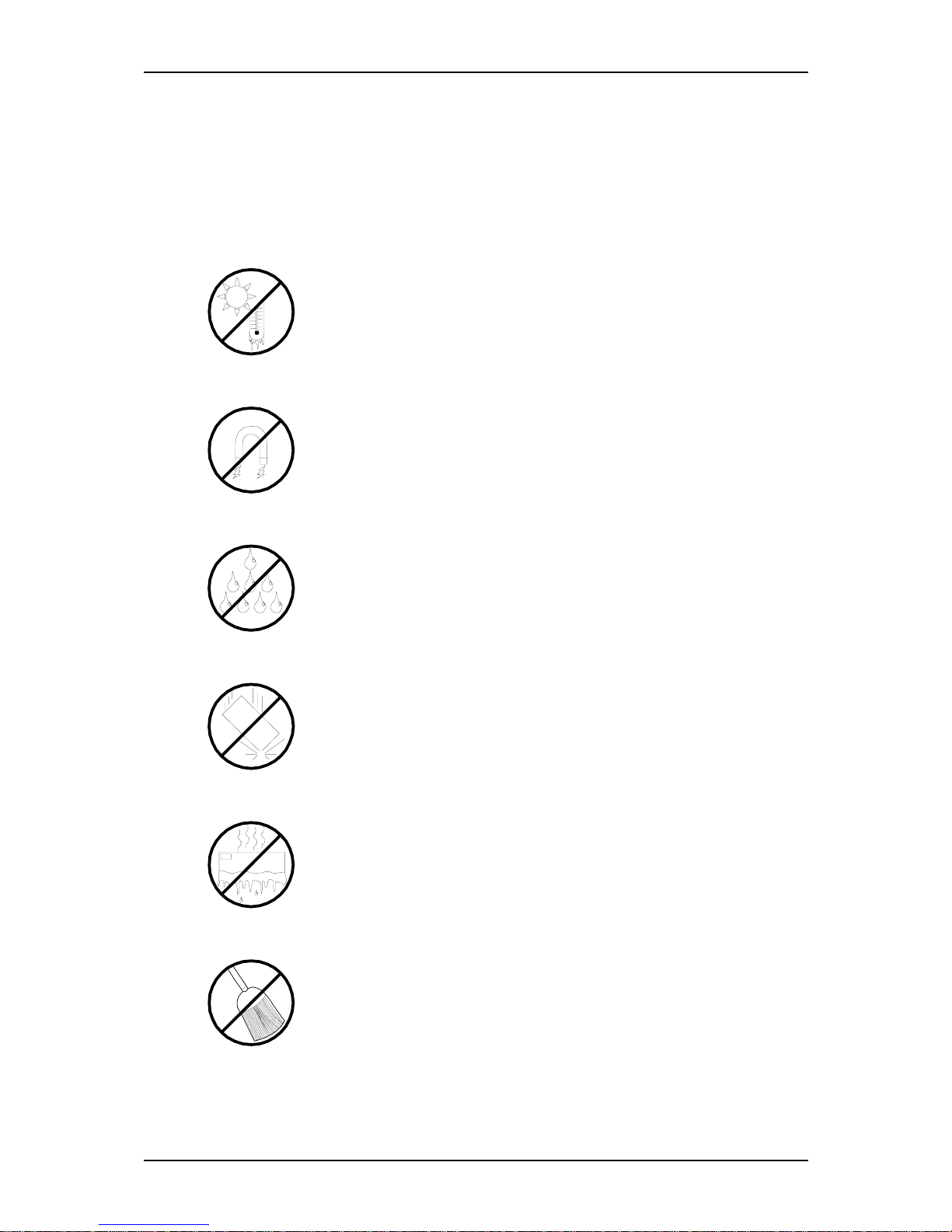
Care and Handling
Use the following guidelines to properly handle and care for your system.
Protect the system from extremely low or high temperatures. Let
the system warm (or cool) to room temperature before using it.
Keep the system away from magnetic forces.
Keep the system dry. Do not wash the system with a wet cloth or pour fluid
into it.
Protect the system from being bumped or dropped.
Check the system for condensation. If condensation exists, allow it to
evaporate before powering on the system.
Keep the system away from dust, sand, and dirt.
Page 15

1
System Overview
■ Overview
■ System Features
■ System Chassis Features
■ Standard Features
■ Optional Features
■ EXPRESSBUILDER CD-ROM
100Syste m Over view
Page 16

I-Select TS100 / I-Select TW100 User Guide - System Overview
1 - 2
Overview
The I-Select TS100 system and the I-Select TW100 system are based on the nVidia
®
CK8-04 Ultra chipset and are designed for the AMD Athlon 64 and the AMD Athlon
64FX processors.
The nVidia® CK8-04 Ultra chipset offers essential features for entry-level server applications, such as:
■ Web hosting
■ Domain name server
■ File and print services
■ E-mail
■ Firewall
■ Proxy
■ Virtual private network
Both I-Select TS100 and I-Select TW100 systems are conveniently housed in a minitower chassis that can also easily be installed into a standard EIA 19-inch rack cabinet.
To get comfortable with your computer, take a tour around your system by reading the
sections hereafter.
Page 17

I-Select TS100 / I-Select TW100 User Guide - System Overview
1 - 3
System Features
Your system features the following major components:
■ AMD Athlon
TM
64 or AMD AthlonTM 64FX processor.
■ Three 32-bit PCI 2.2 expansion slots for bus master PCI cards like LAN cards with
133MB/s maximum throughput.
■ Two PCI-E x1 slots for PCI-E x1 compatible devices such as LAN cards.
■ One PCI-E x16 slot for High Definition Video Boards.
■ Embedded PC-compatible support (serial, diskette, USB, LAN, audio).
■
RAID/ S-ATA controller providing high performance RAID0/ RAID1 functionality.
■ Onboard Ethernet LAN.
■ 3 ½-inch diskette drive.
■ One slot, 3.5-inch media device bay.
■ Four slot, 5,25-inch media device bay.
■ Six integrated Universal Serial Bus (USB) ports, two located on the front panel and
four located on the rear panel.
■ Minitower chassis that can be installed in a standard IEA rack cabinet.
Page 18
I-Select TS100 / I-Select TW100 User Guide - System Overview
1 - 4
System Chassis Features
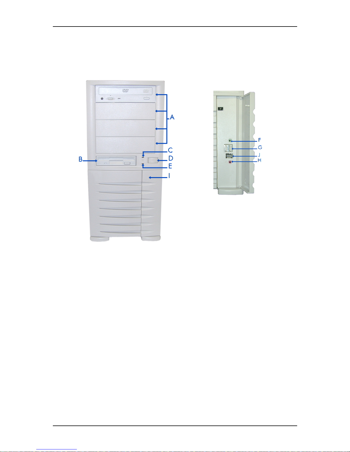
Front View
The following figure shows the location of the front system features
Figure 1 - 1 : Front View
A 5.25-inch bays F Headphone connector
Four 5.25-inch bays, one of which may include a
tape backup unit, CD-ROM drive, DVD-ROM drive
or COMBO DVD-ROM CD-RW drive.
B 3.5-inch bay G USB ports
One 3.5-inch bay that may include a 3.5-inch
floppy disk drive.
Two Universal Serial Bus (USB) ports allow
you to connect USB-equipped peripheral
devices such as printers.
C IDE device lamp H Stereo microphone in connector
Lights up when a hard disk drive or an optical drive
is active, reading or retrieving data.
D Power button I Front door
Press this switch to turn on/off the power. Refer to
the ‘Powering On Your System’, ‘Powering Off the
Server System’ and ‘Forcing a Power Shutdown’
sections hereafter for details.
Open the front door to access the headphone
connector, the stereo microphone in connector
and the USB ports.
E Status lamp J IEEE port
Indicates whether the computer is on or off. A
steady green lamp indicates the computer is on.
The lamp lights amber when the computer is in
stand-by mode.
Front View Detail
Page 19
I-Select TS100 / I-Select TW100 User Guide - System Overview
1 - 5
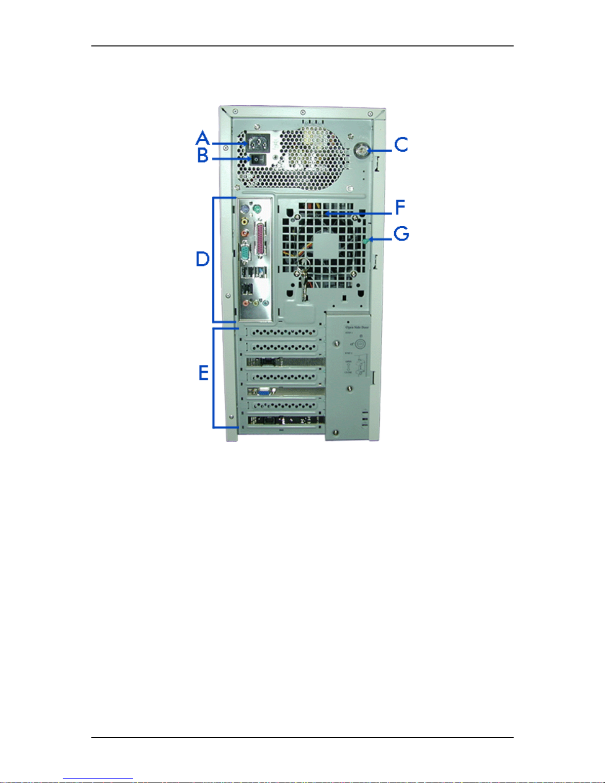
Rear View
Figure 1 - 2 : Rear View
A AC power connector
Connect the power cord to this socket.
B Power switch
C Key lock and intrusion switch
Security feature that allows you to open the right side door and to be noticed when your
chassis has been opened
D Connectors
Refer to the ‘System Connectors’ section hererafter for details.
E Expansion boards slots
Refer to the ‘Expansion Boards Slots’ section hererafter for details
F Venting holes
Keep the area near the venting holes clear for proper ventilation.
G Side cover latch
Push the latch up to enable the right side door opening.
Page 20
I-Select TS100 / I-Select TW100 User Guide - System Overview
1 - 6
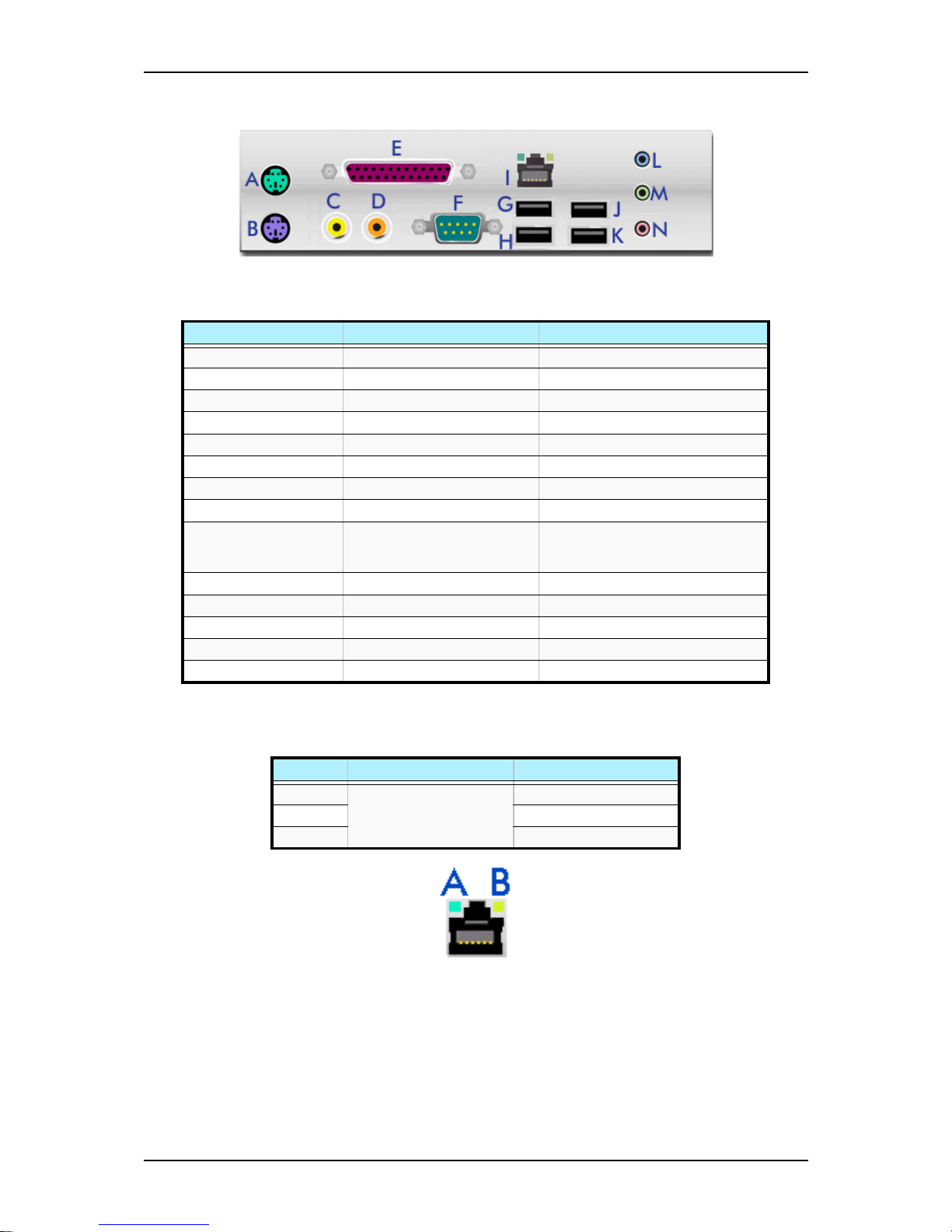
System Connectors
Figure 1 - 3 : System Connectors
RJ45 Leds
Figure 1 - 4 : RJ45 Leds
Expansion Board Slots
Three PCI expansion slots, one PCI-E x16 expansion slot and two PCI-E x1 expansion
slots are available enabling you to install additional Video Boards and LAN board.
Refer to the ‘Optional Features’ section for details about the components that may be
installed in the expansion slots.
Table 1 - 1: System Connectors
Key to the diagram Name of the Port Description
A PS/2 mouse port 6 Pin Mini-DIN
B PS/2 keyboard port 6 Pin Mini-DIN
C S-PDIF connector in
D S-PDIF connector out
E Printer/ EPP/ ECP & BPP port 25 pin SUB D
F Serial port COM1 9 pin SUB D
G USB port 1
H USB port 2
I RJ45 LAN connector and
LEDs. Refer to the RJ45 Leds
section below for details.
RJ45
J USB port 3
K USB port 4
L Stereo line in Jack socket
M Stereo line out Jack socket
N Mono microphone in Jack socket
Table 1 - 2: RJ45 Leds Activity
Speed Led A Activity Led B Activity
10 Always ON (orange)
Lights OFF when active
OFF
100 ON (orange)
1000 ON (green)
Page 21

I-Select TS100 / I-Select TW100 User Guide - System Overview
1 - 7
Internal View
Figure 1 - 5 : Internal View
A Power supply slot
B Motherboard
C 5.25-inch devices slots
D 3.5-inch devices slots
E Hard disk drives slots
Page 22

I-Select TS100 / I-Select TW100 User Guide - System Overview
1 - 8
Motherboard
Figure 1 - 6 : Motherboard
Table 1 - 3: I-Select TS100 / I-Select TW100 Motherboard Internal Connectors
Denomination on
drawing
Name Type
ATX Power connector 24 pin keyed connector
PCIE_16 PCI Express x16 connector PCI Express x16 expansion slot
PCIE_1 PCI Express x1 connectors PCI Express x1 expansion slots
SYS_FAN System fan connector 3 pin header
+12V PWR Power connector 4 pin keyed connector
FDD Floppy Drive connector 34 (2x17) pin Shrouded Header
IDE IDE connector 40 (2x20) pin header (white)
SATA-0, 1, 2 & 3 Serial ATA connectors
PCI 1, 2 & 3 PCI connectors Standard PCI expansion slots
CPU CPU connector 939 pin socket
F2_1394 IEEE connector 2x8 pin header (-1 key)
F1_1394 IEEE connector 2x5 pin header (-1 key)
CPU_FAN CPU fan connector 3 or 4 pin header
DDR1, 2, 3 & 4 DIMM sockets 184 pin standard sockets
Page 23
I-Select TS100 / I-Select TW100 User Guide - System Overview
1 - 9
CD_IN CD-ROM audio line in 4 pin header (black)
F_AUDIO Audio connector 2x5 pin header (-1 key)
CI Chassis intrusion connector 2 pin header
BAT CMOS battery socket
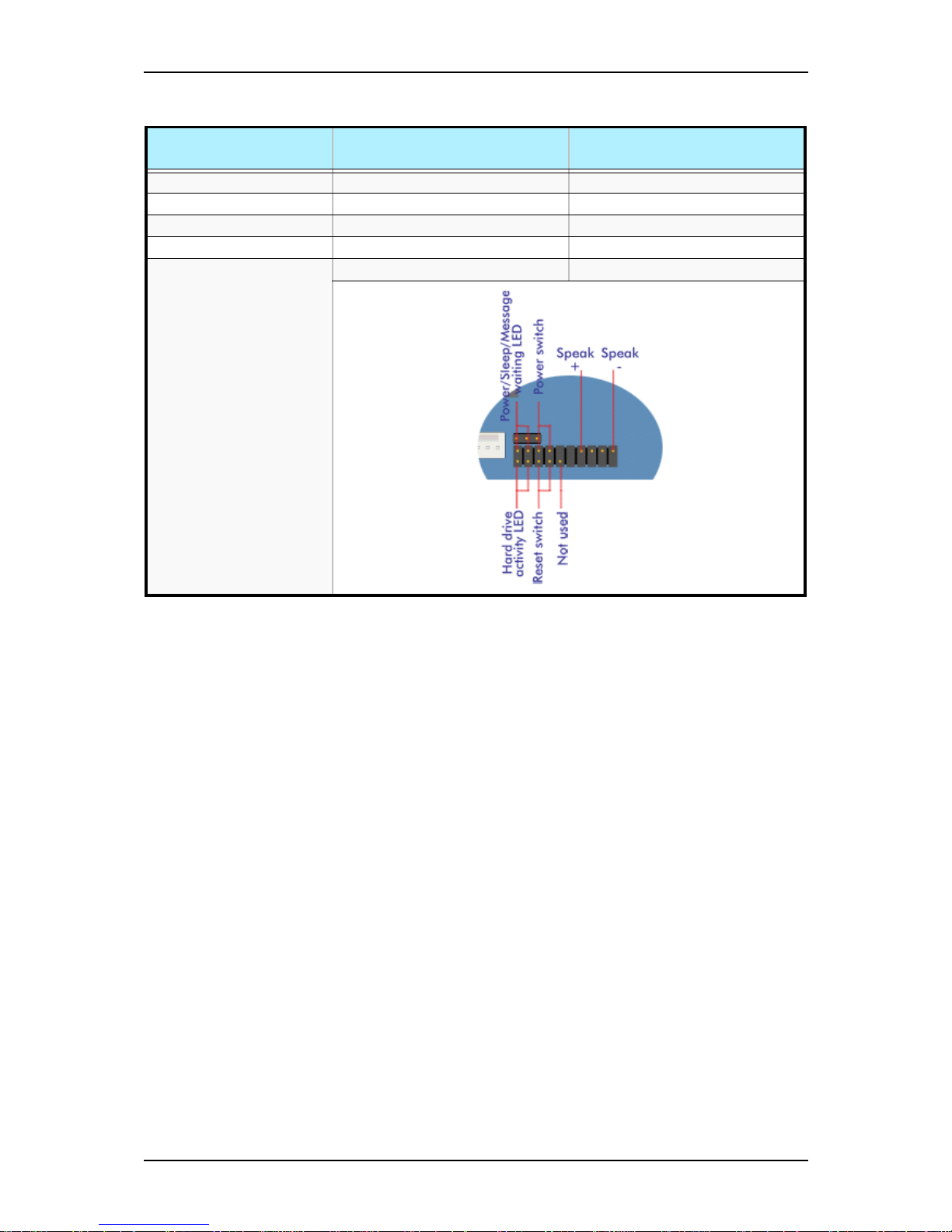
F_PANEL Front panel connector 2x5 pin header (-1 key)
Table 1 - 3: I-Select TS100 / I-Select TW100 Motherboard Internal Connectors
Denomination on
drawing
Name Type
Page 24

I-Select TS100 / I-Select TW100 User Guide - System Overview
1 - 10
Standard Features
■ 400W power supply
■ On-board LAN
■ AMD Athlon 64 and AMD Athlon 64FX processors support
■ Dual channel memory architecture support
■ SCSI and S-ATA hard disk drives support
■ DVD-ROM, COMBO DVD-ROM/ CD-RW, DVD+R9 (DL) support
■ PCI and PCI-E x16 video boards support
■ PCI-E x1 LAN board support
■ 5.25-inch tape backup unit support
Processor
The system board may accommodate one AMD Athlon 64 processor with up to 512KB
cache or one AMD Athlon 64FX processor with up to 1MB cache.
Memory
The system board contains four 184-pin DIMM slots each supporting either DDR400
ECC unbuffered memory or DDR400 non ECC memory. You may install a minimum
of 256 MB and as much as 4 GB.
Caution
You may use either ECC or non ECC memory in your TW100
configuration. However, mixing ECC and non ECC memory is
not supported.
Your system supports dual-channel memory architecture. Refer to “Recommended
Memory Configuration” on page 4-20 for details.
PCI Slots
The motherboard has three PCI expansion slots that you can use to add a video board or
a LAN board for example.
PCI -E x16 Slot
The motherboard has one PCI-E x16 expansion slot that you can use to add a video
board.
Page 25

I-Select TS100 / I-Select TW100 User Guide - System Overview
1 - 11
PCI -E x1 Slots
The motherboard has two PCI-E x1 expansion slot that you can use to add a LAN
board.
Network Controller
Note: To ensure EMC product regulation compliance, the
system must be used with a shielded LAN cable.
The nVidia chipset on the motherboard supports 1GB channel LAN.
ACPI
The motherboard supports the Advanced Configuration and Power Interface (ACPI) as
defined by the ACPI 2.0 specifications. An ACPI aware operating system can put the
system into a state where the hard drives spin down, the system fans stop, and all
processing is halted. However, the power supply will still be on and the processors will
still be dissipating some power, so the power supply fans will still run.
The system board supports sleep states s0, s1, s4, and s5:
■ s0: Normal running state.
■ s1: Processor sleep state. No context will be lost in this state and the processor
caches will maintain coherency.
■ s3: Suspend to RAM: Your working environment is saved to RAM.
Keyboard and Mouse
The keyboard/mouse controller is PS/2-compatible.
Peripheral Bays
Your system features four 5.25-inch bays that you can use with either a hard disk drive,
an optical device such as a DVD-ROM, a COMBO DVD-ROM CD-RW, a DVD+R9
(DL) or a tape backup unit. You can also use two of these bays to install an optional
hot-swap SCSI hard disk drive bay or an optional hot-swap S-ATA hard disk drive bay.
See “Optional Features” on page 1-12.
Page 26

I-Select TS100 / I-Select TW100 User Guide - System Overview
1 - 12
Optional Features
You will find hereafter information about the optional components that may be
installed in your system.
DVD-ROM Drive
■ High Speed DVD: 16X max & High Speed CD: 40X max.
■ Buffer: 256 kBytes
■ Emergency Eject: Pin-hole on front panel to release tray.
■ Software Ejection/ Loading and Volume Control
■ Form Factor: 5.25" half height.
■ Compatibility: DVD-ROM (single-layered and dual-layered), DVD-R 3.95GB &
4.7GB, DVD+R, DVD-RW (rev 1.0 & 1.1), DVD+RW, DVD-RAM 2.6GB & 4.7
GB, CD-ROM Mode1 and Mode2 data disc, CD-R,CD-RW,CD-ROM XA, CD-I,
Photo-CD Multi-session, CD-Extra, CD TEXT, CD Audio disc, Mixed mode CDROM disc.
■ Transfer rate (max):
- CD-ROM: 6000Kbytes/s
- DVD-ROM: 22.1 Mbytes/s
■ CD-ROM ATA Interface (burst):
- 16.6 Mbytes/s (PIO Mode 4/ MULTI word DMA Mode 2)
- 8.3 Mbytes/s (Single word DMA Mode 2)
- 66.7 Mbytes/s (Ultra DMA Mode 4)
■ Rotation Speed:
- CD-ROM: 8780 rpm
- DVD-ROM: 9420 rpm
■ Full Stroke:
- CD-ROM: 160 ms
- DVD-ROM: 180 ms
■ Environmental Specifications:
Table 1 - 4: DVD-ROM Drive Environmental Specifications
Operating Non-operation
Temperature 5°C to 45°C -40°C to +60°C
Humidity (% relative humidity) 15% to 85% 10% to 90%
Vibration 0.25 G (zero to peak) 50 G (zero to peak)
Page 27
I-Select TS100 / I-Select TW100 User Guide - System Overview
1 - 13
DVD-ROM CD-RW Combination Drive
■ Emergency Eject: Pin-hole on front panel to release tray.
■ Volume Control: headphones volume control knob.
■ Headphone jack: 3.5 mm. stereo headphone output on the front panel.
■ Form Factor: 5.25" half height
■ Enhanced IDE Interface
■ Multifunction device:
- 48x CD-ROM reader (Read only)
- 48x CD-Recorder (Write once, read many)
- 24x CD-ReWritable device (Rewritable, read many)
- 16x DVD reader
■ Data buffer: 2MB
■ Compatibility:
- Reads data in each CD-ROM, CD-ROM XA, CD-I, Video CD, CD-Extra, CDText, Photo CD (Single and Multi session), DVD-ROM, DVD-R(Ver.1.0, Ver.
2.0 for Authoring), CD-DA
- Reads and writes CD-R, CD-RW, DVD-R (Ver. 2.0), DVD-RW, DVD+R and
DVD+RW
■ Access time (max):
- CD-ROM: 120ms
- DVD-ROM: 140ms
■ Performance:
■ Environmental Specifications:
Table 1 - 5: Combo Drive Performance
CD-ROM CD-R DVD CD-RW DVD+R/+RW
Reading Speed 48x 48x 16x 16x ~40x 1,7x ~8x
Writing Speed 21x ~48x 4x, 8x, 12x,
16x, 24x
Table 1 - 6: Combo Drive Environmental Specifications
Operating Non-operation
Temperature 5°C to 45°C -30°C to +60°C
Humidity (% relative humidity) 15% to 80% 15% to 95%
Vibration 0.30 G (5-500 Hz) 2.0 G (5-500 Hz)
Page 28
I-Select TS100 / I-Select TW100 User Guide - System Overview
1 - 14
DVD+R9 (DL) Drive
■ Manual Load/Eject Button
■ Drive State and Single LED Specification (green)
■ Form Factor: 5.25" half height
■ Enhanced IDE Interface
■ Multifunction device:
- 48x CD-ROM Reader
- 24x CD-RW Writer (for high speed CD-RW)
- 16x DVD reader
- 4x DVD+R-DL/16x DVD-R/4x DVD-RW/16x DVD+R/4x DVD+RW
■ Data buffer: 2MB
■ Compatibility:
- Reads data in each CD-Audio(8cm/12cm), CD-ROM (mode 1 and mode 2),
CD-ROM XA (mode 2, form 1 and form 2), Photo CD (single or multiple sessions), CD-I(FMV), Video CD, CD Extra., CD-TEXT
- Writes CD-Audio(8cm/12cm), CD-ROM (mode 1 and mode 2), CD-ROM XA
(mode 2, form 1 and form 2), Photo CD (single or multiple sessions), CDI(FMV), Video CD, CD Extra., CD-TEXT
■ Transfer rate:
Table 1 - 7: DVD+R9 (DL) Transfer rate
Write Read
DVD+R
16x CAV 9 - 22 Mbytes/sec
13x CAV 7.3 - 17.5MBytes/sec
12xZCLV 8.2 - 16.6Mbytes/sec
8x ZCLV 5.5 -11MBytes/sec
6x ZCLV 5.5-8.2MBytes/sec
4x CLV 5.5 MBytes/sec
2.4x CLV 3.3 MBytes/sec
DVD-ROM
Single Layer 6.6-16x CAV 9-22 Mbytes/sec
Dual Layer 3-7x CAV 4.1-10 Mbytes/sec
DVD-R/+R
6.6-16x CAV 9-22 Mbytes/sec
DVD+R-DL
2-5x CAV 2.7-6.9 Mbytes/sec
DVD+R-DL
4x CLV 5.5 MBytes/sec
2.4x CLV 3.3 MBytes/sec
DVD+RW/-RW
3.3-8x CAV 4.5-11 Mbytes/sec
DVD+RW
4x CLV 5.5 MBytes/sec
2.4x CLV 3.3 MBytes/sec
DVD-Video with CSS protection
2-5x CAV 2.7-6.9 Mbytes/sec
DVD-R
16x CAV 9 – 22 MBytes/sec
13x CAV 7.3 – 17.5 MBytes/sec
12x ZCLV 8.2 – 16.6 MBytes/sec
8x ZCLV 5.5 -11 MBytes/sec
6x ZCLV 5.5-8.2 MBytes/sec
4x CLV 5.5 MBytes/sec
2x CLV 2.7 MBytes/sec
CD-ROM/CD-R
Mode 1 and Mode 2 Form 1 (2048 Bytes)
20-48x CAV 3000 - 7200 kBytes/sec
CD-RW
Mode 1 and Mode 2 Form 1 (2048 Bytes)
13-32x CAV 1950 - 4800 kBytes/sec
Page 29
I-Select TS100 / I-Select TW100 User Guide - System Overview
1 - 15
Intel Pro 1000 MT LAN Board
■ IEEE Standard
■ 10BASE-T, 100BASE-TX, 1000BASE-T
■ Intel® SingleDriver
TM
Technology
■ Plug and Play Specification Support
■ Easy Installation, Intel® PROSet Utility and Intel® PRO Intelligent Install
■ Auto-negotiation, Full-duplex capable
■ Full height bracket
■ Wired for Management (WfM) Baseline 2.0 Enabled for servers
■ DMI 2.0 support, WMI & SNMP-manageable
■ Offline diagnostics
■ Intel® Boot Agent
■ ACPI Power Management
■ PXE 2.0
PCI-E x1 Syskonnect LAN Board
■ IEEE Standard
■ 10/100/1000BASE-T
■ Full height bracket
■ TCP, UDP and IP checksum calculation
DVD-RW
4x CLV 5.5 MBytes/sec
2x CLV 2.7 MBytes/sec
1x CLV 1.38 MBytes/sec
DAE
13-32x CAV 1950 - 4800 kBytes/sec
CD-R
48x CAV 3000-7200kBytes/sec
48x ZCLV 3000-7200kBytes/sec
40x CAV 2550-6000kBytes/sec
40x ZCLV 3000-6000kBytes/sec
32x PCAV 2550-4800kBytes/sec
32x ZCLV 3000-4800kBytes/sec
24x PCAV 2550-3600kBytes/sec
24x ZCLV 3000-3600kBytes/sec
16x CLV 2400kBytes/sec
8x CLV 1200kBytes/sec
Mode 2 and Mode 2 Form2
8x CLV 1200 kBytes/sec
CD-RW
24x ZCLV 3000-3600kBytes/sec
16x CLV 2400kBytes/sec
10xCLV 1500kBytes/sec
4xCLV 600kBytes/sec
Table 1 - 7: DVD+R9 (DL) Transfer rate
Write Read
Page 30

I-Select TS100 / I-Select TW100 User Guide - System Overview
1 - 16
■ Jumbo frames support
■ TCP segmentation
■ Dynamic Interrupt Moderation
■ Promiscuous Mode/ Multicast support
■ Alert Standard Format (ASF)
■ PXE/ RPL support
■ Advanced Power Management/ Wake on LAN
■ Link Aggregation
■ Redundant Switch Failover
■ PCI Express Hot-Plug
■ Parity
■ Virtual LAN (VLAN) support
■ Virtual Cable Tester
TM
(VCT)
S-ATA Hard Disk Drive
■ Capacity: 80gb minimum
■ 7200RPM
■ RAID0, RAID1 and RAID0+1 support
SCSI Hard Disk Drive
■ Capacity: 73gb minimum
■ 10000RPM
■ RAID0 and RAID1 support (with optional SCSI board)
Caution
You may use either S-ATA or SCSI hard disk drives. However,
mixing S-ATA and SCSI hard disk drives is not supported.
S-ATA Hard Disk Drives Cage
■ The hard disk drive bays for installing up to three S-ATA hard disk drives.
SCSI Hard Disk Drives Cage
■ The hard disk drive bays for installing up to three SCSI hard disk drives.
Page 31

I-Select TS100 / I-Select TW100 User Guide - System Overview
1 - 17
Video Board
Note: Your system may feature a video board of a different
type than those presented hereafter.
nVidia Quadro FX 540 PCI-E x16 Video Board
■ GPU core clock: 300MHz
■ GPU voltage: 1.30v nominal
■ Connectors: Single link DVI-I, VGA, HDTV out 9-pin mini-DIN
■ Memory configuration: 128MB (eight pieces of 8MB x 16 DDR SDRAM)
■ Memory clock: 275MHz
■ Interface: 128 bits
■ DAC resolution/ refresh (max): 2048x1536x32 bpp at 75 Hz
■ Internal single link TMDS (optional DVI-I) with reduced blanking: 1600x1200x32
bpp at 60 Hz
nVidia Quadro NVS280 PCI-E x16 Video Board
■ GPU core clock: 300MHz
■ GPU voltage: 1.35v +/- 30mV
■ Connectors: 59-pin DMS-59 connector
■ Memory configuration: 64MB (four pieces of 8MB x 16 DDR)
■ Memory clock: 200MHz
■ Interface: 64 bits
■ Display resolution/ refresh (max): 2048x1536x32 bpp at 75 Hz
■ Dual internal TMDS (dual DVI)
■ Maximum resolution over digital port: 1280x1024
PCI Video Board
■ Memory configuration: 8MB
■ Bus specifications: PCI bus/ PCI 2.2
■ Output: CRT
■ Resolution support:
- 2D/3D resolution: 1600x1200 max
- Color depth: 16,7m colors max
Page 32

I-Select TS100 / I-Select TW100 User Guide - System Overview
1 - 18
Sony AIT1 Tape Backup Unit
■ Capacity:
- 25 GBytes with 170 meter tape AIT-1 cassette (65 Gbytes with 2.6:1 data compression ratio)
- 35 Gbytes with 230 meter tape AIT-1 cassette (91 Gbytes with 2.6:1 data compression ratio)
■ Sustained transfer rate: 4 Mbytes/sec (10.4 Mbytes/sec with 2.6:1 data
compression ratio)
■ Supported format: AIT-1
■ Not compatible with the DDS and EXABYTES format tapes
■ Burst transfer rate: 66 Mbytes/sec Ultra DMA (mode 4)
■ Large 10 MB buffer memory
■ ATA / ATAP I - 5 i n te r f a c e
■ Supports Fixed record length only
■ Read After Write (RAW) On and Off capability
■ Read Retry On and Off capability
■ Frame rewrite function
■ Three levels of Error Correction Code (ECC)
■ High speed search (120 times nominal Read/Write speed)
■ Random read, Append write
■ Repeat write function
■ MIC support (Automatic reliability and performance enhancement - read and write
capability for MIC user data area)
Sony AIT2 Tape Backup Unit
■ Capacity:
- 50 Gbytes with 230 meter tape AIT-2 cassette (130 Gbytes using the data compression function)
- 35 Gbytes with 170 meter tape AIT-1 cassette (91 Gbytes using the data compression function)
DAT72 Tape Backup Unit
■ Capacity:
- 36 GBytes (72 Gbytes using the data compression function)
Page 33

I-Select TS100 / I-Select TW100 User Guide - System Overview
1 - 19
EXPRESSBUILDER CD-ROM
What You Can Do With the EXPRESSBUILDER CD
■ Create diskettes (third party software drivers).
■ Do Windows Server 2003 or Windows XP Professional Hard Disk Installation
using Express Setup. See “Installing the Operating System and Drivers with
Express Setup” on page C-1.
Software End User License Agreement
Carefully read the terms and conditions of the Software End User License Agreement
printed on the EXPRESSBUILDER CD-ROM sleeve.
Page 34

Page 35

2
Setting Up Your System
■ Overview
■ Selecting a Site
■ Unpacking the System
■ Rack Installation Kit Assembly
■ Making Connections
■ Connecting the Power Cord
■ Using the System
Page 36

I-Select TS100 / I-Select TW100 User Guide - Setting Up Your System
2 - 2
Overview
This chapter describes how to:
■ select a site
■ unpack the system
■ install the system into a standard EIA 19-inch rack cabinet
■ make cable connections
■ power on/off the system
Information on front and rear panel features, switches and LEDs are also included in
this chapter.
Page 37

I-Select TS100 / I-Select TW100 User Guide - Setting Up Your System
2 - 3
Selecting a Site
The system operates reliably in a typical office environment.
You may also choose to install the system into a standard EIA 19-inch rack cabinet
(See “Rack Installation Kit Assembly” on page 2-5).
In both cases, choose a site that is:
■ Near grounded, three-pronged power outlets.
Note: For the United States and Canada, this means a
NEMA 6-15R outlet for 200-240 VAC. The system cannot be
used on a NEMA 5-15R outlet for 100-120 VAC. For other
international sites, this means three-pronged power outlets
applicable for the electrical code of the region.
Warning
Be sure the power service connection is through a properly
grounded outlet.
■ Clean, dust-free, and well ventilated. Every side ventilating openings kept free of
obstructions. Away from sources of heat, vibration or physical shock.
■ Isolated from strong electromagnetic fields and electrical noise produced by
electrical devices (such as air conditioners, large fans, large electric motors, radio
and TV transmitters, and high-frequency security devices)
■ Spacious enough around the system to allow proper cooling, airflow, and cable
clearance.
Caution
Leave enough space behind the system. Not doing so may
result in overheating and damaging the system.
■ Easily accessible for system maintenance and installation of system upgrades.
Page 38

I-Select TS100 / I-Select TW100 User Guide - Setting Up Your System
2 - 4
Unpacking the System
When you receive your system, inspect the shipping containers prior to unpacking. If
the shipping boxes are damaged, note the damage, and if possible, photograph it for
reference. After removing the contents of the containers, keep the cartons and the packing materials. If the contents appear damaged when you unpack the boxes, file a damage claim with the carrier immediately.
Page 39

I-Select TS100 / I-Select TW100 User Guide - Setting Up Your System
2 - 5
Rack Installation Kit Assembly
This section provides the assembly instructions for mounting the server into a standard
19-inch rack cabinet.
Unpacking the Rack Installation Kit
Although the rack installation kit is inspected and carefully packaged at the factory,
damage may occur during shipping. Follow these steps for unpacking.
1. Visually inspect the shipping containers; notify your carrier immediately of any
damage.
2. Carefully remove the rack mounting hardware and verify the parts.
■ Support rail assembly front and rear part (left side)
■ Support rail assembly front and rear part (right side)
■ Support rail assemblies fixing screws
■ Rack mounting frame (A in figure 4)
■ Handles (2 pieces, A in figure 1 below)
■ Handles fixing screws (4 pieces, B in figure 1 below)
■ Hex key for frame grubscrews (C in figure 1 below)
Figure 2 - 1 : Handles, screws and hex key
3. If parts are missing or the hardware is damaged, notify your server
representative.
Page 40

I-Select TS100 / I-Select TW100 User Guide - Setting Up Your System
2 - 6
Before You Begin
Before you begin, please review the following cautions, warnings, and general
guidelines.
Warning
Be sure that power to the system is turned off and unplugged.
All voltage is removed only when the power cords are
unplugged.
■ Avoid excessive vibration and shock. Dropping an electronic component can cause
serious damage.
■ Do not disconnect or remove parts other than those specified in the procedure.
■ Do not touch I/O connector pins.
■ All screws are Phillips-head, unless otherwise specified.
■ On completion of any assembly or reassembly, perform a power-on test. If a fault
occurs, verify that the assembly or reassembly was performed correctly. If the
problem persists, see “Problem Solving” in chapter 5 in the TM710 User’s Guide.
Static Precautions
An electrostatic discharge (ESD) can damage disk drives, option boards, and other
components. You can provide some ESD protection by wearing an antistatic wrist strap
attached to chassis ground when handling system components.
Electronic devices can be easily damaged by static electricity. To prevent damage, keep
them in their protective packaging when they are not installed in your system.
Assembly
The following subsection describes how to assemble your rack-mount server into a
standard 19-inch rack cabinet.
Before you begin select an appropriate location in your rack cabinet for the rack-mount
server. To improve rack stability, mount heavier items towards the bottom of the rack
cabinet. If the rack is a stand-alone unit and the rack is more than 75% filled with
components, consider installing an optional stabilizer kit.
Note: When planning your system configuration for the
rack cabinet you should consider the length of the cables that
interconnect system components.
Page 41

I-Select TS100 / I-Select TW100 User Guide - Setting Up Your System
2 - 7
Warning
■ ANCHOR THE EQUIPMENT RACK: The equipment rack must be
anchored to an unmovable support to prevent it from falling
over when one or more servers are extended in front of it on
slide assemblies. The anchors must be able to withstand a
force of up to 113 kg (250 lbs). You must also consider the
weight of any other device installed in the rack.
■ MAIN AC POWER DISCONNECT: You are responsible for install-
ing an AC power disconnect for the entire rack unit. This
main disconnect must be readily accessible, and it must be
labeled as controlling power to the entire unit, not just to the
server(s).
■ GROUNDING THE RACK INSTALLATION: To avoid the potential
for an electrical shock hazard, you must include a third wire
safety grounding conductor with the rack installation. If a
server power cord is plugged into an AC outlet that is part of
the rack, then you must provide proper grounding for the
rack itself. If server power cords are plugged into wall AC
outlets, the safety grounding conductor in each power cord
provides proper grounding only for the server. You must provide additional, proper grounding for the rack and other
devices installed in it.
Caution
Temperature: The operating temperature of the server, when
installed in an equipment rack, must not go below 5 °C or rise
above 35 °C. Extreme fluctuations in temperature can cause a
variety of problems in your server.
Ventilation: The equipment rack must provide sufficient airflow
to the front of the server to maintain proper cooling. It must also
include ventilation sufficient to exhaust a maximum of 4,100
Btu's per hour for the server. The rack selected and the
ventilation provided must be suitable to the environment in
which the server will be used.
Note: For vertical reference, every three screw holes on
the rack vertical mounting rail are equal to 1U (1.75 inches).
Mounting holes in the vertical rails of equipment racks are
commonly spaced in a 5/8 x 5/8 x 1/2-inch sequence. Perform
the following steps carefully; brackets must be mounted with
precision to allow room for the next server you install in a rack.
Page 42

I-Select TS100 / I-Select TW100 User Guide - Setting Up Your System
2 - 8
Installing the Support Rails
1. Install the right support rail (A in figure 2) as shown in figure 2.
2. Secure the rail to the front (B in figure 2) and rear (C in figure 2) vertical
mounting rails with three screws (D in figure 2) and the washer plate (E in
figure 2).
Figure 2 - 2 : Installing the right support rail
3. Insert two caged nuts (F in figure 2) as shown in figure 2. One in the hole just
above the support rail, the other one eight holes above. Insert the caged nuts in
the front mounting rail as follows (see figure 3):
■ Position the caged nut on the inside of the front vertical mounting rails.
■ Hook the side lip of a caged nut into the square hole in the rail.
Page 43

I-Select TS100 / I-Select TW100 User Guide - Setting Up Your System
2 - 9
■ Push the other side lip of the caged nut into the square hole in the rail
until it is secured.
■ Repeat for each caged nut.
Figure 2 - 3 : Inserting a caged nut
4. Repeat steps 1 to 3 for the left support rail.
Attaching the Handles to the Rack Mounting Frame
Two handles are attached to the rack mounting frame. The handles are used to easily
slide the server in and out of the rack.
Warning
The handles are only used to slide the server in and out of the
rack. DO NOT use these handles to carry the server.
Attach the handles (A in figure 1) to the rack mounting frame with two screws (B in
figure 1).
Installing the Rack Mounting Frame on the Server
Install the rack mounting frame on the server as follows:
1. Remove the right side door as described in “Removing or Installing the Right
Side Door” in chapter 4 of the TM 710 User’s Guide.
2. Remove the front panel as described in “Removing and Replacing the Front
Panel” in chapter 4 of the TM 710 User’s Guide.
Page 44

I-Select TS100 / I-Select TW100 User Guide - Setting Up Your System
2 - 10
3. Install the rack mounting frame (A) on the server (B) as shown in figure 4
below.
Figure 2 - 4 : Installing the rack mounting frame on the server
4. Slide the rack mounting frame on the server until the front of the server
protrude a little from the frame.
5. Replace the front panel.
6. Replace the right side door.
7. Align the rack mounting frame (A in figure 5) with the rear of the front panel (B
in figure 5).
8. Secure the frame with the grubscrews (C in figure 5, four on each side) using
the hex key (C in figure 1), enough to fix the frame to the server but not too
much to prevent damage to the server case.
Figure 2 - 5 : Securing the rack mounting frame
Page 45

I-Select TS100 / I-Select TW100 User Guide - Setting Up Your System
2 - 11
Installing the Server in the Rack Cabinet
Warning
The system can weigh up to 17.5 kg. If it contains numerous
optional boards and peripheral devices, it will weigh more. To
avoid personal injury, make sure you have at least one person
help you lift or move the system.
Do not use the handles of the rack mounting frame to lift the
server.
1. Lift the sever onto the support rails and slide it toward the rear of the cabinet.
2.
Secure the server to the vertical mounting rails with the four thumbscrews
(A in
figure 6)
.
Figure 2 - 6 : Securing the server to the rack cabinet
Page 46

I-Select TS100 / I-Select TW100 User Guide - Setting Up the System
2 - 12
Making Connections
Connect your keyboard, monitor, and mouse. Also connect any external peripheral
devices such as a printer or scanner by following the instructions included with these
devices.
Caution
Damage to the system may result if the keyboard/ mouse cable
is inserted or removed when power is applied to the system.
Inserting a telephone line connector into a LAN RJ-45 port may
result in personal injury and equipment damage.
Connecting the Power Cord
Plug the female end of the AC power cord into the input receptacle on the rear of the
power supply cage. Plug the male end of the power cord into NEMA 5-15R outlet for
100-120 VAC or NEMA 6-15R outlet for 200-240 VAC.
If the power cord(s) supplied with the system is not compatible with the AC wall outlet
in your region, obtain a suitable power cord that meets the following criteria.
■ The power cord must be rated for the available AC voltage and have a current
rating that is at least 125% of the current rating of the system.
■ The power cord connector that plugs into the wall outlet must be terminated in a
grounding-type male plug designed for use in your region. It must have
certification marks showing certification by an agency acceptable in your region.
■ The power cord connector that plugs into the system must be an IEC- type CEE-22
female connector.
■ The power cord must be less than 1.8 meters (6.0 feet) long.
Warning
Do not attempt to modify or use the supplied AC power cord if it
is not the exact type required.
Page 47

I-Select TS100 / I-Select TW100 User Guide - Setting Up Your System
2 - 13
Using the System
The following subsections describe how to use this system properly and safely, including an explanation of the system power on/off sequences, what the POST program
checks in the system, and how to perform a forced power shutdown.
When using the system the following precautions should be observed.
■ Make sure you power off the system before connecting or disconnecting cables
between the system and peripheral devices. Connecting or disconnecting the cables
while the system is powered on may cause malfunction or failures within the system.
■ Verify that the access lamp on the diskette drive is unlit before turning off the sys-
tem or ejecting the floppy disk. Turning off the system or ejecting the floppy disk
while the access lamp is lit may damage data being stored on the floppy disk.
■ After turning off the system, wait at least 10 seconds before turning it on again.
Cycling the power immediately may cause malfunction or failures of the system.
■ Before relocating the system, turn off the power and unplug the power cord from
the outlet. Moving the system when it is powered may cause malfunction or failures of the system.
■ Some software includes a command to eject the CD-ROM tray or a media in a
device mounted in the 5.25-inch device bay. Make sure that the front door of the
tower-based cabinet is open before running the command. Running this command
with the front door closed may cause the CD-ROM tray or the media to hit against
the front door, resulting in a possible failure of the CD-ROM.
■ Clean the system regularly. Regular cleaning prevents failures of the system and its
components.
■ Lightning may cause a momentary voltage drop. To prevent this problem, an unin-
terruptible power supply unit is recommended.
■ Only use options qualified for the system. A non-qualified option may be mounted
or connected to the system, but it may fail to operate normally or even cause failures. These types of failures are not covered under warranty.
Page 48

I-Select TS100 / I-Select TW100 User Guide - Setting Up Your System
2 - 14
Powering On your System
Caution
■ If the power cord is connected to a power control device
such as a UPS (Uninterruptible Power Supply), make sure
that the power control device is powered.
■ Do not turn off the system until characters following the
Boot-BIOS logo display on the screen.
Power on your system as follows.
1. Make sure all external devices, such as a video display, keyboard, and mouse
(optional) have been connected, and the power cords are connected.
2. Power on the video display and any other external devices.
Note: If the system power cord(s) is connected to a power
control unit such as an UPS (Uninterruptible Power Supply)
make sure that the power control unit is powered on.
3. Press lightly on the front connectors door to open it.
4. Press the POWER switch to power on the system. The POWER lamp lights
green. If it is not lit, ensure the ac power cord is connected to a functional ac
power source.
After a few seconds your system begins the internal Power-On Self Tests (POST).
POST automatically checks the system board, CPU(s), memory, keyboard, mouse, and
most installed peripheral devices. POST also displays the start messages of the BIOS
setup utility during execution.
The POST check results should be checked in the following cases:
■ When the system is being used for the first time.
■ When the system appears to fail.
■ When the system beeps many times between power-on and OS start-up.
■ When an error message appears on the screen.
Note: For error messages that appear on the display unit,
refer to subsection POST Error Codes and Messages in Chapter 5 of this Guide.
Page 49

I-Select TS100 / I-Select TW100 User Guide - Setting Up Your System
2 - 15
Caution
Always allow POST to complete before powering down your
system.
If you have problems powering on your system, refer to Problem Solving in Chapter 5
of this User’s Guide.
After you have successfully powered on your system, insert the EXPRESSBUILDER
CD-ROM into the CD-ROM device, reboot the system and follow the screen prompts
to run EXPRESSBUILDER.
Powering Off your System
When system power is on, pressing the power on/off switch on the front panel of the
system turns the power off.
To turn the system power off:
1. Shutdown the operating system (OS).
2. If necessary, press the POWER switch on the front of the computer chassis
again to power off the system. The POWER lamp lights off.
3. Power off the peripheral devices.
Note: If the system power cord is connected to a power
control unit such as an UPS (Uninterruptible Power Supply),
refer to the UPS user's guide for proper power-off procedures.
Forcing a Power Shutdown
A forced power shutdown can be used when the power on/off switch does not power
off the system.
To perform a forced power shutdown:
■ Press in on the power on/off switch located on the front panel of the system for at
least 4 seconds to force the system power off.
To power on after a forced shutdown, wait 10 seconds and then power on again.
Page 50

Page 51

3
Configuring Your System
■ Configuring Your System
■ BIOS Setup Utility
■ Configuring MotherBoard Jumpers
Page 52

I-Select TS100 / I-Select TW100 User Guide - Configuring Your System
3 - 2
Configuring Your System
Configuration and setup utilities are used to change your system configuration. You can
configure your system, as well as option boards you may add to your system, using the
BIOS Setup Utility. Several unique system parameters are configured using the BIOS
Setup, which is stored in the system FLASH memory.
If your system has been factory configured, the BIOS Setup Utility does not need to be
run unless you want to change the password or security features, add certain types of
option boards or devices, or upgrade your system board.
This chapter also provides information on several system configuration parameters that
are set by jumpers on the system board. However, these parameters do not usually
require change.
Page 53

I-Select TS100 / I-Select TW100 User Guide - Configuring Your System
3 - 3
BIOS Setup Utility
The BIOS Setup Utility is used to change system configuration parameters. The utility
is resident in the system FLASH memory and does not require a diskette or an operating system present to run.
Using the BIOS Setup Utility
You access the BIOS Setup utility when you turn on or reboot your system. To run the
BIOS Setup Utility, perform the following procedure:
1. Power-on or reboot the system. “Press <DEL> to enter SETUP” displays.
2. Press DEL. The BIOS Setup Utility starts and the Main Menu is displayed. The
Main Menu lists the following selections:
Use the arrow keys to select a menu or an item on a displayed menu. Press the value
keys (listed in the table below) to cycle through the allowable values for the selected
field. Use the “Save & Exit Setup” item to save the current values on all the menus.
To display a submenu, position the cursor on a selection that has a submenu and press
ENTER. An arrow precedes selections with submenus.
Refer to the following table for information on the keys that you use with BIOS Setup.
These keys are also listed at the bottom of the Setup menu.
Table 3 - 1: Main Menu
Display Use
Standard CMOS Features Use this menu for basic system configuration.
Advanced Use this menu for setting the Advanced Features available on your system.
Integrated Peripherals Use this menu for setting onboard IO, IRQ, DMA assignment.
Power Management Setup Use this menu for setting your system’s power management.
PnP/PCI Configurations Use this menu to configure server specific options.
PC Health Status Use this menu to display server information.
MB Intelligent Tweaker (M.I.T.) Use this menu to change CPU’s clock and voltage
Load Optimized Defaults Press Enter to load factory default values.
Set Supervisor Password Press Enter to set a supervisor password.
Set User Password Press Enter to set a user password.
Save & Exit Setup Press Enter to save and exit the BIOS Setup utility
Exit Without Saving Press Enter to exit without saving changes.
Table 3 - 2: BIOS Setup Keys
Key Function in Setup Menu
F1 Get Help about an item.
ESC Exit the current menu and return to the previous menu.
Left or right arrow keys Move between menus.
Up or down arrow keys Move cursor up and down. The cursor moves only to the settings
that you can change.
Page 54

I-Select TS100 / I-Select TW100 User Guide - Configuring Your System
3 - 4
BIOS Setup Configuration Settings
The BIOS Setup Configuration tables show the default settings for the BIOS Setup
Utility and provide a place for you to record any changes you make to these settings.
Recommended values are bold in the following tables.
Note: The BIOS present on your system may feature more
or less options that described here.
F5 Load previous values.
F7 Load default configuration values for this menu.
F10 Save configuration values.
+ / - Increase or decrease values.
ENTER Execute command or Select submenu.
Table 3 - 2: BIOS Setup Keys (Continued)
Key Function in Setup Menu
Page 55

I-Select TS100 / I-Select TW100 User Guide - Configuring Your System
3 - 5
Standard CMOS Features Menu
IDE Channel 0 Master/ 0 Slave/ 1 Master/ 1 Slave Submenu
Table 3 - 3: Standard CMOS Features Menu
Feature Choices or
Display Only
Description Your Setting
Date MM/DD/YYYY Set the System Date.
Time HH:MM:SS Set the System Time.
IDE Channel 0 Master LITE-ON COMBO
LTC -48
Press Enter to display submenu
IDE Channel 0 Slave None Press Enter to display submenu
IDE Channel 1 Master None Press Enter to display submenu
IDE Channel 1 Slave None Press Enter to display submenu
Drive A None
360K, 5.25”
1.2M, 5.25”
720K, 3.5”
1.44M, 3.5”
2.88M, 3.5”
Allows you to configure floppy
drive A.
Floppy 3 Mode Support Disabled
Drive A
Allows you to enable the Floppy
3 Mode support.
Halt On All Errors
No Errors
All, But Keyboard
All, But Diskette
All, But Disk/Key
Allows you to configure the
system boot stops.
Table 3 - 4: IDE Channel 0 Master Submenu
Feature Choices or
Display Only
Description Your Setting
IDE HDD AutoDetection
Press Enter Press Enter for the system to
detect hard drive
IDE Channel 0
Master/ 0 Slave/ 1
Master/ 1 Slave
None
Auto
Manual
Allows you to set hard drive
parameters
Capacity Display only Displays the device capacity
Cylinder Display only Displays the device number of
cylinders
Head Display only Displays the device number of
heads
Precomp Display only Displays the device precomp
Landing Zone Display only Displays the device landing
zone
Sector Display only Displays the device number of
sectors
Page 56

I-Select TS100 / I-Select TW100 User Guide - Configuring Your System
3 - 6
Advanced BIOS Features Menu
Table 3 - 5: Advanced BIOS Features Menu
Feature Choices or
Display Only
Description Your Setting
Hard Disk Boot
Priority
Select submenu In the submenu, specify the 1st
drive from the option.
First Boot Device Floppy
LS120
Hard Disk
CDROM
ZIP
USB-FDD
USB-ZIP
USB-CDROM
Allow you to specify the boot
device priority order
Second Boot Device Floppy
LS120
Hard Disk
CDROM
ZIP
USB-FDD
USB-ZIP
USB-CDROM
Third Boot Device Floppy
LS120
Hard Disk
CDROM
ZIP
USB-FDD
USB-ZIP
USB-CDROM
Boot Up Floppy
Seek
Disabled
Enabled
Enable or disable the Boot Up
Floppy Disk functionality
Password Check Setup
System
Allows you to configure
password check
Init Display First PCI Slot
PEG
Configure video priority
Page 57

I-Select TS100 / I-Select TW100 User Guide - Configuring Your System
3 - 7
Integrated Peripherals Menu
Table 3 - 6: Integrated Peripherals Menu
Feature Choices or
Display Only
Description Your Setting
On-Chip IDE Channel0 Disabled
Enabled
Configure the On-Chip IDE
Channel0
On-Chip IDE Channel1 Disabled
Enabled
Configure the On-Chip IDE
Channel1
IDE DMA transfer access Disabled
Enabled
Configure the IDE DMA transfer
access
On-Chip MAC Lan Disabled
Auto
Configure the On-Chip MAC
Lan
On-Chip LAN BOOT ROM Disabled
Enabled
Decide whether to invoke the
boot ROM of the onboard LAN
chip
IDE/SATA RAID function Disabled
Enabled
Enable or disable the IDE/SATA RAID function
IDE Primary Master RAID Disabled
Enabled
Configure RAID for the
specified device
IDE Primary Slave RAID Disabled
Enabled
IDE Secndry Master RAID Disabled
Enabled
IDE Secndry Slave RAID Disabled
Enabled
Serial-ATA 1 Enabled
Disabled
Enable or disable Serial-ATA 1
SATA 1 Primary RAID Enabled
Disabled
Configure RAID for the
specified device
SATA 1 Secondary RAID Enabled
Disabled
Serial-ATA 2 Enabled
Disabled
Enable or disable Serial-ATA 2
SATA 2 Primary RAID Enabled
Disabled
Configure RAID for the
specified device
SATA 2 Secondary RAID Enabled
Disabled
IDE Prefetch Mode Enabled
Disabled
Enable or disable IDE prefetch
mode
On-Chip USB Disabled
V1.1+V2.0
V1.1
Configure USB support
USB Memory Type SHADOW
Base
Memory(640K)
Configure USB memory type
USB Keyboard Support Disabled
Enabled
Enable or disable USB
keyboard support
USB Mouse Support Disabled
Enabled
Enable or disable USB mouse
support
AC97 Audio Disabled
Auto
Configure AC97 Audio
Onboard 1394 Enabled
Disabled
Enable or disable onboard
1394
Page 58

I-Select TS100 / I-Select TW100 User Guide - Configuring Your System
3 - 8
Onboard Serial Port 1 Disabled
3F8/IRQ4
2F8/IRQ3
3E8/IRQ4
2E8/IRQ3
Auto
Configure onboard serial port 1
Onboard Parallel Port Disabled
378/IRQ7
278/IRQ5
3BC/IRQ7
Configure onboard parallel port
Parallel Port Mode SPP
EPP
ECP
ECP+EPP
Configure parallel port mode
ECP Mode Use DMA Display only Displays the ECP Mode Use
DMA value
CIR Port Address Disabled
310
320
Set the CIR port address
CIR Port IRQ Display only Displays the CIR Port IRQ
Table 3 - 6: Integrated Peripherals Menu (Continued)
Feature Choices or
Display Only
Description Your Setting
Page 59

I-Select TS100 / I-Select TW100 User Guide - Configuring Your System
3 - 9
Power Management Setup Menu
Table 3 - 7: Power Management Setup Menu
Feature Choices or
Display Only
Description Your Setting
ACPI Suspend Type S1(POS)
S3(STR)
Configure ACPI Suspend type
Soft-Off by Power
button
Delay 4 Sec
Instant-Off
Configure soft-off by power
button
PME Event Wake UpDisabled
Enabled
Enable or disable PME event
wake up
Modem Ring On Disabled
Enabled
Enable or disable modem ring
on
USB Resume from
Suspend
Disabled
Enabled
Enable or disable USB resume
from suspend mode
Power-On by Alarm Disabled
Enabled
Enable or disable power-on by
alarm
Day of Month Alarm Everyday, 01, 02,
03, 04, 05, 06, 07,
08, 09, 10, 11, 12,
13, 14, 15, 16, 17,
18, 19, 20, 21, 22,
23, 24, 25, 26, 27,
28, 29, 30, 31
Set day of month alarm.
“Power-On By Alarm” must be
set to “Enabled”
Time (hh:mm:ss)
Alarm
Time Settings Configure time of alarm.
“Power-On By Alarm” must be
set to “Enabled”
Power On By
Mouse
Disabled
Double-Click
Configure power-on by mouse
Power On by
Keyboard
Disabled
Password
Any KEY
Keyboard 98
Configure power-on by
keyboard
KB Power ON
Password
5 characters field Set keyboard power-on
password.
“Power On By Keyboard” must
be set to “Password”
AC BACK Function Soft-Off
Full-On
Configure AC BACK function
Page 60

I-Select TS100 / I-Select TW100 User Guide - Configuring Your System
3 - 10
PnP PCI Configurations Menu
Table 3 - 8: Boot Menu
Feature Choices or
Display Only
Description Your Setting
PCI 3 IRQ
Assignment
Auto,3, 4, 5, 7, 9, 10,
11, 12, 14, 15
Configure PCI IRQ
assignments
PCI 4 IRQ
Assignment
Auto,3, 4, 5, 7, 9, 10,
11, 12, 14, 15
PCI 1 IRQ
Assignment
Auto,3, 4, 5, 7, 9, 10,
11, 12, 14, 15
PCI 2 IRQ
Assignment
Auto,3, 4, 5, 7, 9, 10,
11, 12, 14, 15
Page 61

I-Select TS100 / I-Select TW100 User Guide - Configuring Your System
3 - 11
PC Health Status Menu
Table 3 - 9: PC Health Status Menu
Feature Choices or
Display Only
Description Your Setting
Reset Case Open
Status
Disabled
Enabled
Enable or disable to reset the
case open status
Case Opened Display only Indicates if the chassis has
been opened
Vcore Display only CPU voltage information
DDR25V Display only RAM voltage information
+3.3V Display only Voltage information
+12V Display only Voltage information
Current CPU
Temperature
Display only Indicates CPU current
temperature
Current CPU FAN
Speed
Display only Indicates CPU fan current
speed
Current POWER
FAN Speed
Display only Indicates power fan current
speed
Current SYSTEM
FAN Speed
Display only Indicates system fan current
speed
CPU Warning
Temperature
Disabled
60°C/140°F
70°C/158°F
80°C/176°F
90°C/194°F
Configure the CPU warning
temperature
CPU FAN Fail
Warning
Disabled
Enabled
Enable or disable the CPU fan
fail warning
POWER FAN Fail
Warning
Disabled
Enabled
Enable or disable the power fan
fail warning
CPU Smart FAN
Control
Disabled
Enabled
Enable or disable the CPU
smart fan control
Page 62

I-Select TS100 / I-Select TW100 User Guide - Configuring Your System
3 - 12
MB Intelligent Tweaker Menu
Table 3 - 10: MB Intelligent Tweaker Menu
Feature Choices or
Display Only
Description Your Setting
CPU Frequency 200.0 to 400.0 Set CPU frequency
CPU Spread
Spect ru m
Disabled
Center Spread
Enable CPU Spread Spectrum
K8 CPU Clock Ratio Maximum
x4 800Mhz
x5 1000Mhz
x6 1200Mhz
x7 1400Mhz
x8 1600Mhz
x9 1800Mhz
Set CPU clock ratio
Robust Graphics
Booster
Auto
Fast
Turbo
Configure RGB function
CPU Voltage
Control
Normal
800V to 1.750V
Set CPU voltage
CAUTION: CPU may be
damaged or CPU life-cycle may
be reduced when CPU is overvoltage
Normal CPU Vcore 1.400V
PCI-E Graphic
voltage
Normal
+0.1v
+0.2v
+0.3v
Set CPU voltage
CAUTION: CPU may be
damaged or CPU life-cycle may
be reduced when CPU is overvoltage
HT-Link voltage
control
Normal
+0.1v
+0.2v
+0.3v
Set HT-Link voltage
CAUTION: CPU may be
damaged or CPU life-cycle may
be reduced when CPU is overvoltage
DDR voltage control Normal
+0.1v
+0.2v
Set DDR voltage
CAUTION: CPU may be
damaged or CPU life-cycle may
be reduced when CPU is overvoltage
Page 63

I-Select TS100 / I-Select TW100 User Guide - Configuring Your System
3 - 13
Configuring MotherBoard Jumpers
Your system’s motherboard has one jumper setting: Clear CMOS jumper
(CLR_CMOS).
1. Power off the system and unplug the AC power cord.
2. The jumper is placed on one pin only: remove the jumper and position it on both
pins.
3. Wait 2 seconds.
4. Reposition the jumper on one pin only.
5. Power on the system. The message ‘CMOS checksum error, Defaults loaded’
displays.
6. Press DEL to enter setup.
7. Select ‘Load optimized defaults’.
8. Save and exit.
Figure 3 - 1 : Clear CMOS Jumper
Page 64

Page 65

4
Upgrading Your System
■ General Information
■ Static Precautions
■ Equipment Log
■ Tools Recommended for Upgrading Your System
■ Preparing Your System for Upgrade
■ Removing or Installing the Right Side Door
■ Removing and Replacing the Front Panel
■ Installing and Removing the Hard Disk Drive Cage
■ Cabling the Hard Disk Drive Cage
■ Installing or Removing a 5.25-inch Device
■ Installing or Removing a 3.5-inch Floppy Disk Drive
■ Installing or Removing Hard Disk Drives
■ Upgrading Microprocessor
■ Upgrading Random Access Memory (RAM)
■ Installing and Removing an Expansion Card
■ Replacing the Battery
■ Cabling the Device
■ Preparing the Device
Page 66

I-Select TS100 / I-Select TW100 User Guide - Upgrading Your System
4 - 2
General Information
Warning
The DC push-button on/off switch on the front panel does not
turn off completely the system AC power. Also, +5vdc is present
on the system board whenever the AC power cord is connected
between the system and an AC outlet. Before doing the procedures in this manual, make sure that your system is powered off
and unplug the AC power cord from the back of the chassis.
Failure to disconnect power before opening your system can
result in personal injury and equipment damage.
Caution
Operating your system with the side access panels removed
can damage your system components. For proper cooling and
airflow, always replace the side access panels before powering
on your system.
Warning
Avoid burns: If the system has been running, any installed processor and heat sink on the processor board(s) will be hot. To
avoid the possibility of a burn, be careful when removing or
installing components that are located near processors.
Contact your sales representative or dealer for a list of approved optional peripheral
devices.
Static Precautions
An electrostatic discharge (ESD) can damage disk drives, option boards, and other
components. You can provide some ESD protection by wearing an antistatic wrist strap
attached to chassis ground when handling system components.
Electronic devices can be easily damaged by static electricity. To prevent damage, keep
them in their protective packaging when they are not installed in your system.
Page 67

I-Select TS100 / I-Select TW100 User Guide - Upgrading Your System
4 - 3
Equipment Log
Use the equipment log form located at the end of this manual to record the model and
serial number of your system, all installed options, and any other pertinent information
specific to your system. You will need this information when configuring your system.
Tools Recommended for Upgrading Your
System
Depending on the upgrade, you will need one or more of the following tools:
■ Phillips screwdriver (#1 bit and #2 bit)
■ Flat-head screwdriver
■ Small needle nose pliers
■ Pen or pencil
■ ESD workstation or antistatic wrist strap (recommended)
Preparing Your System for Upgrade
To prepare your system for installation or removal of system components perform the
following procedure:
1. Observe the safety and ESD precautions listed under General Information and
Static Precautions at the beginning of this chapter.
2. Shutdown the operating system (OS).
3. If necessary, press the power on/off switch on the front panel of the system (see
See “Powering On your System” on page 2-14.). The power-on LED goes out.
4. Power off the peripheral devices.
5. Unplug the system power cord(s) from the AC wall outlet(s).
Note: If the system power cord is connected to a power
control unit such as an UPS (Uninterruptible Power Supply),
refer to the UPS user's guide for proper power-off procedures.
6. Unplug all the I/O cables connected to the rear panel of your system.
Page 68

I-Select TS100 / I-Select TW100 User Guide - Upgrading Your System
4 - 4
Removing or Installing the Right Side Door
The right side door provides access to the disk drive bays, to the motherboard and to
the 5.25 and 3.5-inch bays.
Removing the Right Side Door
1. Make sure the power switches for the computer, video monitor and any periph-
eral devices are turned OFF and unplug the power cord (see the 'Safety Precautions' chapter).
2. Disconnect the monitor and peripheral devices (printers, for instance) from the
system.
3. Unlock the key lock.
Figure 4 - 1 : Key lock
4. Lift the release latch on the back of your system as shown in the picture below.
Figure 4 - 2 : Right Side Door Release Latch
5. Carefully slide the right side door about two centimetres towards the back of the
unit. Please note that you may find this procedure easier to follow if you lay the
unit on the left side.
6. Lift the right side door away from the computer
Page 69

I-Select TS100 / I-Select TW100 User Guide - Upgrading Your System
4 - 5
Replacing the Right Side Door
Avoid damaging your system - before replacing the right side door, make sure no
cables or other devices protrude from the chassis.
Note: If you have previously removed the front panel, be
sure to fasten it securely to the chassis before restoring the
cover. The front panel must be securely connected to the
chassis before you replace the cover.
1. Take a few moments to examine the interior side of the cover, and notice the 2
rails on two separate edges and the 3 slots located on a third edge.
2. Leaving about 1 centimetre to slide the cover forward, lay the cover on the chassis, and check that the rail is ready to slide on its corresponding edge and that the
slots are ready to fit with their corresponding metal hooks. You may find this
procedure easier to follow if you lay the unit on the left side.
3. Make sure the cover is properly inserted; the cover, the chassis and the front
panel should fit squarely together.
4. Push the release latch down.
5. Lock the key.
Page 70

I-Select TS100 / I-Select TW100 User Guide - Upgrading Your System
4 - 6
Removing and Replacing the Front Panel
Removing the Front Panel
1. Remove the right side door. See “Removing the Right Side Door” on page 4-4.
2. Locate the front panel release latches (A) and gently pull them to release the left
side of the front panel.
Figure 4 - 3 : Pop-in Tabs
3. Once the left side is free, pivot the front panel toward you until it is totally
released.
Replacing the Front Panel
1. Insert the three tabs located on the left inside of the front panel into their respective slots. You may have to slightly pivot the front panel to aid the process.
2. Gently press on the left (outside) of the front panel until the 4 remaining tabs are
securely inserted into their slots.
3. Replace the right side door. See “Replacing the Right Side Door” on page 4-5.
Page 71

I-Select TS100 / I-Select TW100 User Guide - Upgrading Your System
4 - 7
Installing and Removing the Hard Disk Drive Cage
Installing the Hard Disk Drive Cage
1. Remove the right side door. See “Removing the Right Side Door” on page 4-4.
2.
Remove the front panel. See “Removing the Front Panel” on page 4-6.
3. If necessary, remove the already installed 5.25-inch device. See “Removing a
5.25-inch device” on page 4-11.
4. If necessary, from the inside of the chassis, push on the desired slot cache with
your left hand and hold it with your right hand outside the chassis.
5. Pivot the cache until it gets released from the frame.
Note:
■ Two slots are necessary to install a hard disk drive cage.
■ The two tabs that hold the cache actually break: this is nor-
mal.
6. Take four slide rails marked as “CD-ROM”. Slide rails come with the system in a
plastic bag.
7. Attach two slide rails onto both sides of the hard disk drive cage as shown in the
picture below.
Figure 4 - 4 : Attaching the Slide Rails
8. Have the relevant cables getting out of the hard disk drive cage slot and connect
them to the hard disk drive cage. See “Cabling the Hard Disk Drive Cage” on
page 4-9.
Page 72

I-Select TS100 / I-Select TW100 User Guide - Upgrading Your System
4 - 8
9. Slide in the hard disk drive cage until hearing a click sound.
Figure 4 - 5 : Installing the Hard Disk Drive Cage
10.
Replace the front panel. See “Replacing the Front Panel” on page 4-6.
11. Replace the right side door. See “Replacing the Right Side Door” on page 4-5.
Note: Modify the BIOS Setup program to recognise the
additional device. For additional information, refer to the
‘Configuring your system’ chapter.
Removing the Hard Disk Drive Cage
1. Remove the right side door. See “Removing the Right Side Door” on page 4-4.
2. Remove the front panel.
See “Removing the Front Panel” on page 4-6.
3. Unconnect the cables from the hard disk drive cage.
4. Press both slide rails ends (A) on each side of the hard disk drive cage to release
it and pull the hard disk drive cage out of the frame.
Figure 4 - 6 : Removing a Hard Disk Drive Cage
5. Replace the front panel.
See “Replacing the Front Panel” on page 4-6.
6. Replace the right side door. See “Replacing the Right Side Door” on page 4-5.
Page 73

I-Select TS100 / I-Select TW100 User Guide - Upgrading Your System
4 - 9
Cabling the Hard Disk Drive Cage
Cabling the SCSI Hard Disk Drive Cage
■ Connect the power cable to the power connector (A)
■ Connect the SCSI cable to the SCSI connector (B)
■ Connect the RAID cable to the RAID connector (C)
Figure 4 - 7 : SCSI Hard Disk Drive Cage
Page 74

I-Select TS100 / I-Select TW100 User Guide - Upgrading Your System
4 - 10
Installing or Removing a 5.25-inch Device
This section of the chapter describes how to add and remove 5.25-inch devices. You
can install a DVD-ROM/ COMBO DVD-ROM CD-RW/ DVD+R9 Drive, tape backup
unit, or other 5-25 inch devices in the additional 5.25-inch bay. See the installation
instructions included with those items for specific installation information. Before
installing a 5.25-inch device, read section “Preparing the Device” on page 4-33.
Adding a 5.25-inch Device
1. Remove the right side door. See “Removing the Right Side Door” on page 4-4.
2.
Remove the front panel. See “Removing the Front Panel” on page 4-6.
3. From the inside of the chassis, push on the desired slot cache with your left hand
and hold it with your right hand outside the chassis.
4. Pivot the cache until it gets released from the frame.
Note: The two tabs that hold the cache actually break: this
is normal.
5. Take two slide rails marked as “CD-ROM”. Slide rails come with the system in a
plastic bag.
6. Attach the slide rails to the upper holes on both side of the 5.25-inch device.
Figure 4 - 8 : Attaching the Slide Rails
7. Slide in the 5.25-inch device until hearing a click sound.
Figure 4 - 9 : Installing the 5.25-inch device
8. Connect the data cable to the device with the marked edge toward pin 1 of the
drive. See “Cabling the Device” on page 4-27.
9. Connect the power cable to the drive. See “Cabling the Device” on page 4-27.
10.
Replace the front panel. See “Replacing the Front Panel” on page 4-6.
11. Replace the right side door. See “Replacing the Right Side Door” on page 4-5.
Note: Modify the BIOS Setup program to recognise the
additional device. For additional information, refer to the
‘Configuring your system’ chapter.
Page 75

I-Select TS100 / I-Select TW100 User Guide - Upgrading Your System
4 - 11
Removing a 5.25-inch device
1. Remove the right side door. See “Removing the Right Side Door” on page 4-4.
2. Remove the front panel.
See “Removing the Front Panel” on page 4-6.
3. Unconnect the power cable and the data cable from the 5.25-inch device.
4. Press both slide rails ends (A) to release the 5.25-inch device
5. Pull the 5.25-inch device out of the frame.
Figure 4 - 10 : Removing a 5.25-inch Device
6. Replace the front panel.
See “Replacing the Front Panel” on page 4-6.
7. Replace the right side door. See “Replacing the Right Side Door” on page 4-5.
Page 76

I-Select TS100 / I-Select TW100 User Guide - Upgrading Your System
4 - 12
Installing or Removing a 3.5-inch Floppy Disk
Drive
Removing a 3.5-inch Floppy Disk Drive
1. Remove the right side door. See “Removing the Right Side Door” on page 4-4.
2. Remove the front panel. See “Removing the Front Panel” on page 4-6.
3. Disconnect the cables from the floppy disk drive.
4. Press both slide rails ends to release the floppy disk drive
5. Pull the floppy disk drive out of the frame.
Figure 4 - 11 : Removing a 5.25-inch Device
6. Replace the front panel.
See “Replacing the Front Panel” on page 4-6.
7. Replace the right side door. See “Replacing the Right Side Door” on page 4-5.
8. Set the floppy disk drive aside.
Installing a 3.5-inch Floppy Disk Drive
1. Remove the right side door. See “Removing the Right Side Door” on page 4-4.
2. Remove the front panel. See “Removing the Front Panel” on page 4-6.
3. Take two slide rails marked as “FDD”. Slide rails come with the system in a plas-
tic bag.
4. Attach the slide rails to the holes on both sides of the floppy disk drive.
Figure 4 - 12 : Attaching the Slide Rails
Page 77

I-Select TS100 / I-Select TW100 User Guide - Upgrading Your System
4 - 13
5. Slide in the floppy disk drive.
Figure 4 - 13 : Installing the 5.25-inch device
6. Connect the data cable to the floppy disk drive with the marked edge toward pin
1 of the drive. See “Cabling the Device” on page 4-27.
7. Connect the power cable to the drive. See “Cabling the Device” on page 4-27.
8.
Replace the front panel. See “Replacing the Front Panel” on page 4-6.
9. Replace the right side door. See “Replacing the Right Side Door” on page 4-5.
Note: Modify the BIOS Setup program to recognise the
additional device. For additional information, refer to the
‘Configuring your system’ chapter.
Page 78

I-Select TS100 / I-Select TW100 User Guide - Upgrading Your System
4 - 14
Installing or Removing Hard Disk Drives
Removing a Hard Disk Drive
1. Remove the right side door. See “Removing the Right Side Door” on page 4-4.
2. Loosen the screw (A) securing the HDD bracket and the 3.5/5.25-inch bracket
together.
3. Locate the HDD bracket latch (B).
Figure 4 - 14 : HDD Bracket Screw and Latch
4. Disconnect the data cable and the power cable from each installed hard disk
drive.
Caution
Be careful when working around the cables connected to the
already installed drives.
If necessary disconnect these cables, but be sure to note which
device each cable or power lead was attached to.
Page 79

I-Select TS100 / I-Select TW100 User Guide - Upgrading Your System
4 - 15
5. Both holding the HDD bracket and pressing down the latch, gently slide the
HDD bracket out of the chassis.
Figure 4 - 15 : Sliding the HDD Bracket out
6. The hard disk drive is secured to the bracket with 3 screws located on both
sides of the hard disk drive. Remove these screws, and slide the hard disk drive
out of the bracket.
7. Set the hard disk drive aside.
Installing a Hard Disk Drive
Caution
Make sure to install hard disk starting from the upper slot.
1. Refer to the information provided with the hard disk drive for pre-installation
instructions and master/slave/cable select pin configurations. See “Preparing
the Device” on page 4-33.
2. Remove the right side door. See “Removing the Right Side Door” on page 4-4.
3. If applicable, disconnect the data and power cables of the installed hard disk
drives.
4. Loosen the screw (A) securing the HDD bracket and the 3.5/5.25-inch bracket
together.
Page 80

I-Select TS100 / I-Select TW100 User Guide - Upgrading Your System
4 - 16
5. Locate the HDD bracket latch (B).
Figure 4 - 16 : HDD Bracket Screw and Latch
Caution
Be careful when working around the cables connected to the
already installed drives.
If necessary disconnect these cables, but be sure to note which
device each cable or power lead was attached to.
6. Notice the screw holes located on each side of the HDD bracket, and the
corresponding screw holes located on the hard disk drive you mean to install.
Making sure the screw holes will line up, slide the hard disk drive into one of
the available slots, connectors last.
7. Secure screws into the three side screw holes of the hard disk drive.
8. Slide the HDD bracket into its original place.
9. Secure the screw loosened in step 5.
10. Connect the data and power cables to their respective hard disk drives. See
“Preparing the Device” on page 4-33.
11. Replace the right side door. See “Replacing the Right Side Door” on page 4-5.
Note: Modify the BIOS Setup program to automatically
recognise the hard disk drive. For additional information, refer
to the BIOS Setup chapter.
Page 81

I-Select TS100 / I-Select TW100 User Guide - Upgrading Your System
4 - 17
Upgrading Microprocessor
Your system is fitted with an AMD (K8) Athlon 64FX processor or an AMD (K8) Athlon 64 processor. This processor is installed in a Socket 939.
Install a processor according to the following procedure.
1. Remove the right side door. See “Removing the Right Side Door” on page 4-4.
2. Disconnect the fan cable from the processor fan connector on the motherboard.
3. Lift the heatsink plastic arms (A).
Figure 4 - 17 : Heatsink Plastic Arms
4. With your finger, gently pull on one of the metallic clips (B) to release the heatsink.
Figure 4 - 18 : Heatsink Metallic Clips
5. When both metallic clips are released, lift the heatsink and set it aside.
6. Locate the processor socket.
Page 82

I-Select TS100 / I-Select TW100 User Guide - Upgrading Your System
4 - 18
7. Lift the lever on the socket and remove the processor.
Figure 4 - 19 : Socket Lever
8. Remove the new processor from its antistatic package and place it on a grounded,
static-free surface or conductive foam pad.
9. Position the processor over the processor socket so that its pins align with the
socket holes.
Figure 4 - 20 : Positioning the Processor
Note: Be aware of processor direction. Pin layouts on two
corners among four differ from others to prevent an incorrect
insertion. Confirm the pin mark and pin layout on the socket,
and insert the processor correctly.
Page 83

I-Select TS100 / I-Select TW100 User Guide - Upgrading Your System
4 - 19
10. Gently apply pressure equally over the top surface of the processor until it seats
in the socket. The processor should fit, do not force the processor into the socket.
Push the socket lever down until it snaps into the locked position.
11. Install the heatsink proceeding as follows:
■ On one side of the heatsink, insert the metal arm notches into the correspond-
ing slots. Push on the heatsink until the hear a click when the other arm is in
place.
■ Secure the heatsink to the system by pushing the two plastic arms down.
Note: Make sure that the heatsink is level.
12. Connect the fan cable to the processor fan connector on the motherboard.
13. Replace the right side door. See “Replacing the Right Side Door” on page 4-5.
Page 84

I-Select TS100 / I-Select TW100 User Guide - Upgrading Your System
4 - 20
Upgrading Random Access Memory (RAM)
Recommended Memory Configuration
Your system is equipped with four memory slots: two purple slots and two orange slots.
When adding memory modules to your system, populate the purple slots first, starting
with the slot closer to the processor.
Your system supports Dual Channel technology. Refer to the table below for memory
dual-channel configuration:
Checking System Memory
If you do not know how much memory is installed in your system, check the amount by
using the relevant following procedure.
Note: The maximum memory size supported in your
system is 4 GB.
1. On the Windows desktop, click on Start, and select Control Panel.
2. Click on Switch to classic view.
3. Double click on the System icon, and click on the General tab. This tab shows
the random access memory (RAM). This is the amount of system memory in
your computer.
Table 4 - 1: Dual Channel Configuration
DDR1 DDR2 DDR3 DDR4
2 memory modules DS/SS DS/SS X X
X X DS/SS DS/SS
4 memory modules DS/SS DS/SS DS/SS DS/SS
Page 85

I-Select TS100 / I-Select TW100 User Guide - Upgrading Your System
4 - 21
Removing a DDR module
Figure 4 - 21 : DDR Memory Module Sample
If your memory configuration requires the removal of a module, perform the following
steps:
1. Remove the computer right side door. See “Removing the Right Side Door” on
page 4-4.
2. Locate the memory upgrade sockets on the motherboard.
3. Press the plastic clips at the outer edge of the socket away from the memory
module. This ejects the memory module from the socket. Do not touch the module's metal "fingers." Store the module in an anti-static bag (available at electronic supply stores) or a cardboard box.
Installing a DDR module
1. Remove the computer right side door. See “Removing the Right Side Door” on
page 4-4.
2. If you need to remove a currently installed memory module, refer to the above
section.
3. Align the new module with an empty memory socket. Make sure the notch on the
module aligns with the key in the socket. The module is designed to install into
the socket in only one way.
4. Press the module firmly into the socket. If you have difficulty installing a module, do not force it! Carefully remove the module, then check the alignment of
the module's notch with the one in the socket. Then re-install the module.
5. Make sure the locking clips at either end of the module click closed. If the brackets do not secure themselves to the module, carefully remove the module, then
reinstall it.
6. Replace the computer right side door. See “Replacing the Right Side Door” on
page 4-5.
Note: The amount of installed memory will be automatically
detected by the system.
Page 86

I-Select TS100 / I-Select TW100 User Guide - Upgrading Your System
4 - 22
Installing and Removing an Expansion Card
Your computer's motherboard features several expansion slots that can accommodate
accessory expansion cards, such as a video board, a SCSI board or a RAID board.
Please refer to section Expansion Cards Resources hereafter for details.
RAID Controller
Take the following into consideration when installing either a S-ATA Disk array
controller or a SCSI Disk array controller. Refer to the manual that comes with the
RAID controller for details.
■ Prepare the hard disk drives and cables corresponding to the RAID controller to be
installed.
■ Configure the Logical Settings of the hard disk drive.
■ Prepare the number of hard disk drives required for desired RAID (Redundant
Array of Inexpensive [Independent] Disks) level.
■ Installing hard disks in the disk array configuration or changing the RAID level
initializes hard disks. Make sure to backup any valuable data that may be present
on the hard disk drive before installing the disk mirroring controller board and
configuring the array.
■ Use hard disks of the same capacity and revolution for each pack to configure them
in the array.
■ The disk array configuration improves disk reliability but provides a smaller disk
capacity than the total capacity of hard disks in the disk array configuration.
■ When the disk array controller board is replaced, restore the disk array
configuration information in the disk array controller board. Use the configuration
utility for the restoration. Refer to chapter 5 for details.
SCSI Controller
Take the following into consideration either when installing an SCSI controller or when
using SCSI hard disk drives as internal hard disk drives. Refer to the manual that comes
with the SCSI controller for details.
■ Prepare the hard disk drives (up to 4 drives) and cables appropriate to SCSI
controller to be installed.
■ Configure the Logical Settings of hard disk drive.
■ When the controller is choosed to boot on OS, install the hard disk controller in the
highest priority PCI slot, i.e. in the smallest PCI slot number.
Page 87

I-Select TS100 / I-Select TW100 User Guide - Upgrading Your System
4 - 23
Figure 4 - 22 : SCSI Controller for Disks or Tapes
400
■ After the installation, set the transfer rate of the board, those of the devices
connected to the board, and other parameters by using the SCSI BIOS utility of the
SCSI controller. Refer to the document coming with the board for the details of the
settings and the procedures.
A External SCSI Connector
B Internal SCSI Connector
C Hard Disc Activity LED Connector (not used)
Page 88

I-Select TS100 / I-Select TW100 User Guide - Upgrading Your System
4 - 24
Installing an Expansion Card
1. Remove the computer right side door. See “Removing the Right Side Door” on
page 4-4.
2. Locate the add-on card holder near the slot you mean to fit with an expansion
card.
Figure 4 - 1 : Add-on Card Holders
3. Pull up the relevant latch and slide it out.
4. Remove the expansion slot cover from the chassis and set it aside. Save the
expansion slot cover in a safe place in case you ever need to replace it.
Figure 4 - 2 : Removing the Expansion Slot Cover
5. Remove your expansion card from its protective packaging. Do not touch the
metal “fingers” on the edge of the card.
6. Check the expansion card's documentation for any switches or jumpers that
may need to be set, and set them now.
7. Carefully, but firmly, press the expansion card into the connector.
8. Replace the computer right side door. See “Replacing the Right Side Door” on
page 4-5.
Page 89

I-Select TS100 / I-Select TW100 User Guide - Upgrading Your System
4 - 25
Removing an Expansion Card from Your System
1. Remove the computer right side door. See “Removing the Right Side Door” on
page 4-4.
2. Locate the add-on card holder near the slot from which you mean to remove an
expansion card.
Figure 4 - 3 : Add-on Card Holders
3. Pull up the relevant latch and slide it out.
4. Do not touch any components on the card - handle it only by its edges, to avoid
risk of damage from electrostatic discharge. Without flexing the motherboard,
carefully unplug the card from its connector on the motherboard, and remove it
from the expansion slot on the chassis' rear panel.
5. Store the expansion card in an anti-static bag (available from electronic supply
stores) or a cardboard box.
6. Place an expansion slot cover in the space left by the expansion card you
removed.
For more details on the location and availability of the expansion card slots on your
system's motherboard, see the section entitled Motherboard.
Expansion Cards Resources
We advise you to install any optional expansion cards accordingly to the following
order:
■ If an AGP board is installed, PCI slots are available in this order: 4, 1, 5, 2, 3.
■ If a PCI board is installed, remaining PCI slots are available in this order: 1, 5, 2, 3.
Caution
■ Do not mix AGP and PCI video boards.
■ Install the Promise Disk Array Controller only in the lowest
PCI slot (slot #5).
Page 90

I-Select TS100 / I-Select TW100 User Guide - Upgrading Your System
4 - 26
Replacing the Battery
All motherboards use a battery to maintain system configuration information. If it fails
to maintain system configuration, replace it with an identical rated battery from the
same manufacturer.
Remove the battery from the motherboard as follows:
Caution
Removing the battery from the motherboard causes the computer to lose system configuration information. Before removing
it, run Setup and record the system configuration settings.
Use this information to restore the system after replacing the
battery.
1. Turn off and unplug the system unit and any external options connected to the
system.
2. Remove the right side door. See “Removing the Right Side Door” on page 4-4.
3. Locate the battery on the motherboard. See “Motherboard” on page 1-8.
4. Use your finger to carefully remove the battery from the battery socket on the
motherboard.
Warning
The battery may explode if it is incorrectly replaced or improperly discarded.
Use only an identical rated battery from the same manufacturer.
5. With the positive (+) side facing up, press the new battery into the socket.
6. Replace the system unit cover.
7. Connect external peripherals and power cables.
8. Run Setup to reconfigure system parameters.
Page 91

I-Select TS100 / I-Select TW100 User Guide - Upgrading Your System
4 - 27
Cabling the Device
The IDE Cable
Depending on your configuration, your system may come with two three-connector
IDE interface cables, one joining your hard disk drive to the primary IDE connector on
the system board, the other joining your CD or DVD-ROM drive to the secondary IDE
connector on the system board.
Each IDE connector on the motherboard supports two devices.
The addition of a device to an IDE connector does not require the replacement of the
existing IDE cable.
The following figure shows a typical three-connector IDE cable. If the IDE cable is not
keyed with a connector tab, align the coloured edge (Pin 1) of the cable with the pin 1
side of the drive connector.
■
A - Connects to the motherboard IDE port
■
B - Red edge (Pin 1)
■
C - Connects to IDE devices
Figure 4 - 4 : Three-connector IDE Cable
Page 92

I-Select TS100 / I-Select TW100 User Guide - Upgrading Your System
4 - 28
The S-ATA Cable
Your system comes equipped with two S-ATA cables.
Both connectors go either to a hard disk drive or to the motherboard.
Figure 4 - 5 : S-ATA Cable
Note: The color of the S-ATA cable may differ from the color
of the cable shown in the picture.
The SCSI Cable
Depending on your configuration, your system may come with a SCSI interface cable.
The connectors are used as follows:
■ one connector plugs into the SCSI adapter card,
■ one or several connectors plug into the hard disk drives (if applicable),
■ one connector plugs into the tape device (if applicable),
■ the last connector is a terminator (mandatory).
The SCSI interface cable is Ultra/320 compliant, meaning that it can transfer data at the
maximum speed of 320MB/s. The connectors are of the 68-pin type, and can only be
fitted one way.
Page 93

I-Select TS100 / I-Select TW100 User Guide - Upgrading Your System
4 - 29
System Power Cables
Power cables come from the power supply and are attached to standard storage devices.
System power cables vary in length and provide connector sizes to accommodate a
variety of supported storage configurations. Power cable connectors are keyed to fit
only in the correct position. The following figures respectively show the power cable
connector for an IDE storage device and the power cable adaptor for a S-ATA device.
Figure 4 - 6 : IDE Storage Device Power Cable Connector
Figure 4 - 7 : S-ATA Storage Device Power Cable Adaptor
Cabling a DVD-ROM, a Combo DVD-ROM CD-RW or a DVD+R9 Drive
All optical devices require power and IDE cable connections. Devices shipped with the
system are already connected.
The following procedure explains how to attach the cables to an optical drive.
1. Connect the IDE cable connector (B) to the matching pins on the storage
device.
■ Take care to prevent bending drive connector pins.
■ Align the cable connector to the matching pins on the drive.
Page 94

I-Select TS100 / I-Select TW100 User Guide - Upgrading Your System
4 - 30
2. Locate an available power connector coming from the power supply.
3. Connect the appropriate power cable (D) to the power connector on the storage
device.
Figure 4 - 8 : Cabling an Optical Device
■ A - Audio Cable - N/A
■ B - IDE cable
■ C - Red edge (Pin 1)
■ D - Power cable
Note: Audio Cable is not available on this system.
Cabling a Hard Disk Drive
All storage devices require power and DATA cable connections. Devices shipped with
the system are already connected.
The following procedures explain how to attach the cables to a hard disk drive.
S-ATA Hard Disk Drive
1. Connect the S-ATA cable connector to the matching pins on the storage device.
■ Take care to prevent bending drive connector pins.
■ Align the cable connector to the matching pins on the drive. Black side
goes to hard disk drive; blue side goes to motherboard. Refer to S-ATA
Hard Disk Drive picture hereafter.
Page 95

I-Select TS100 / I-Select TW100 User Guide - Upgrading Your System
4 - 31
2. Locate an available power connector coming from the power supply.
3. Connect the appropriate power cable to the cable power adaptor.
4. Connect the power cable adaptor to the connector on the storage device.
Figure 4 - 9 : S-ATA Hard Disk Drive
SCSI Hard Disk Drive
All storage devices require power and SCSI cable connections. Devices shipped with
the system are already connected.
The following procedure explains how to attach the cables to a hard disk drive.
1. Connect one of the relevant SCSI cable connectors (A) to the matching pins on
the storage device.
- Take care to prevent bending drive connector pins.
- Align the cable connector to the matching pins on the drive.
2. Locate an available power connector coming from the power supply.
3. Connect the appropriate power cable (B) to the power connector on the storage
device.
A - SCSI cable
B - Power cable
Page 96

I-Select TS100 / I-Select TW100 User Guide - Upgrading Your System
4 - 32
Cabling a Floppy Disk Drive
All storage devices require power and data cable connections. Devices shipped with the
system are already connected.
The following procedure explains how to attach the cables to a floppy disk drive.
1. Connect the data cable connector (A) to the matching pins on the storage
device.
■ Take care to prevent bending drive connector pins.
■ Align the cable connector to the matching pins on the drive.
2. Locate an available power connector coming from the power supply.
3. Connect the appropriate power cable (C) to the power connector on the storage
device.
Figure 4 - 10 : Cabling a Floppy Disk Drive
■ A - Data cable
■ B - Purple edge (Pin 1)
■ C - Power cable
Page 97

I-Select TS100 / I-Select TW100 User Guide - Upgrading Your System
4 - 33
Preparing the Device
Note: Please note that in normal operation mode, the
‘cable select’ position is recommended for all IDE devices.
Preparing an Optical Drive
Before installing a CD/DVD-ROM drive in the system, the jumper on the back of the
drive must be set as “cable select”. Refer to the ‘IDE Device Configuration’ hereafter
for details about configuring IDE drives as master or slave. Refer to the instructions
printed on the device for further jumper setting information.
■ A - Jumper block
Figure 4 - 11 : Connectors on the Back of an Optical Drive (example)
■ A - Master
■ B - Slave
■ C - Cable select
Figure 4 - 12 : Jumper settings (example)
Preparing a S-ATA Hard Disk Drive
S-ATA hard disk drives do not need being prepared.
Page 98

I-Select TS100 / I-Select TW100 User Guide - Upgrading Your System
4 - 34
Preparing a SCSI Hard Disk Drive
Before installing a SCSI hard disk drive in the system, it should be set as ID0, ID1, ID2
or ID3.
Refer to the instructions printed on the device for further jumper setting information.
Preparing an IDE Tape Drive
Before installing a tape drive in the system, it should be set as a master or a slave
device using the drive select jumper at the back of the drive. Refer to the ‘IDE Device
Configuration’ hereafter for details about configuring IDE drives as master or slave.
Refer to the instructions printed on the device for further jumper setting information.
■ Master Setting
■ Slave Setting
■ Cable Select
Figure 4 - 13 : Connectors on the Back of a Tape Drive (example)
Preparing a SCSI Tape Drive
Before installing a SCSI tape drive in the system, it should be set as ID0, ID1, ID2 or
ID3.
Refer to the instructions printed on the device for further jumper setting information.
Page 99

5
Problem Solving
■ Problem Solving
■ Static Precautions
■ Resetting the System
■ Troubleshooting Guide
■ Problems at initial System Start-up
■ Problems After the System Has Been Running Correctly
■ Problems Running New Application Software
■ Problems and Suggestions
■ If You Need Assistance
■ Error Messages
■ Error Messages: Beep Codes
■ How to Identify BIOS Revision Level
Page 100

I-Select TS100 / I-Select TW100 User Guide - Problem Solving
5 - 2
Problem Solving
This chapter helps you identify and solve problems that may occur during system
installation or while using your system. The first section of this chapter tells you how to
reset your system in the event of problems. The next few sections provide
troubleshooting checklists and procedural steps that help you isolate specific system
problems. The last section includes BIOS and system user information.
Warning
The DC push-button on/off switch on the front panel does not
turn off the system AC power. Also, +5vdc is present on the system board whenever the AC power cord is connected between
the system and an AC outlet. Before doing the procedures in
this manual, make sure that your system is powered off and
unplug the AC power cords from the back of the chassis. Failure to disconnect power before opening your system can result
in personal injury and equipment damage
Caution
Operating your system with the cover removed can damage
your system components. For proper cooling and airflow,
always replace the right side panel before powering on your
system.
Static Precautions
An electrostatic discharge (ESD) can damage disk drives, option boards, and other
components. You can provide some ESD protection by wearing an antistatic wrist strap
attached to chassis ground when handling system components.
Electronic devices can be easily damaged by static electricity. To prevent damage, keep
them in their protective packaging when they are not installed in your system.
 Loading...