

Page 1

PROPRIETARY NOTICE AND LIABILITY DISCLAIMER
The information disclosed in this document, including all designs and related materials, is
the valuable property of NEC Corporation (NEC) and/or its licensors. NEC and/or its licensors, as appropriate, reserve all patent, copyright and other proprietary rights to this
document, including all design, manufacturing, reproduction, use, and sales rights thereto,
except to the extent said rights are expressly granted to others.
The NEC product(s) discussed in this document are warranted in accordance with the terms
of the Warranty Statement accompanying each product. However, actual performance of
each such product is dependent upon factors such as system configuration, customer data,
and operator control. Since implementation by customers of each product may vary, the
suitability of specific product configurations and applications must be determined by the
customer and is not warranted by NEC.
To allow for design and specification improvements, the information in this document is
subject to change at any time, without notice. Reproduction of this document or portions
thereof without prior written approval of NEC is prohibited.
Image and MultiSync are U.S. registered trademarks of NEC Technologies, Inc.
FastFacts and NEC SVGA are U.S. trademarks of NEC Technologies, Inc.
All other product, brand, or trade names used in this publication are the trademarks or registered
trademarks of their respective trademark owners.
First Printing — February 1995
Copyright 1995 Copyright 1995
NEC Technologies, Inc. NEC Corporation
1414 Massachusetts Avenue 7-1 Shiba 5-Chome, Minato-Ku
Boxborough, MA 01719 Tokyo 108-01, Japan
All Rights Reserved All Rights Reserved
Page 2

Contents
Preface............................................................................................................................. xv
Abbreviations.................................................................................................................. xvii
Section 1 Technical Information
System Unit..................................................................................................................... 1-1
System Board........................................................................................................... 1-2
Chipset............................................................................................................. 1-6
PCI and Memory Controller (PCMC).................................................... 1-6
Local Bus Accelerators .......................................................................... 1-6
PCI-EISA Bridge Component................................................................ 1-7
EISA System Component (ESC)............................................................ 1-7
Bus Architecture.............................................................................................. 1-7
Host Bus....................................................................................................... 1-8
iii
PCI Bus ........................................................................................................ 1-9
EISA Bus...................................................................................................... 1-9
XD Bus......................................................................................................... 1-9
System Memory Bus.................................................................................... 1-9
Processor.......................................................................................................... 1-9
Secondary Cache.............................................................................................. 1-10
Flash ROM....................................................................................................... 1-10
On-Board Peripherals ...................................................................................... 1-12
SCSI Circuitry.............................................................................................. 1-12
IDE Controller.............................................................................................. 1-12
Video Circuitry............................................................................................. 1-12
EISA SRAM................................................................................................. 1-12
Real-Time Clock (RTC)............................................................................... 1-13
System I/O Controller...................................................................................... 1-13
I/O Mapping..................................................................................................... 1-13
NEC Proprietary Ports..................................................................................... 1-15
Keyboard Controller Ports............................................................................... 1-20
System Memory............................................................................................... 1-21
Interrupt Controller.......................................................................................... 1-22
Video Controller.............................................................................................. 1-23
Video Memory................................................................................................. 1-23
EISA Bus ......................................................................................................... 1-23
Page 3

iv Contents
PCI Local Bus.................................................................................................. 1-26
PCI Auto Configuration................................................................................... 1-26
Parallel Interface.............................................................................................. 1-26
Serial Interface................................................................................................. 1-27
Indicator Panel ......................................................................................................... 1-28
Power Supply........................................................................................................... 1-28
Diskette Drive.......................................................................................................... 1-28
Hard Disk Drive....................................................................................................... 1-28
Quad-Speed IDE CD-ROM Reader......................................................................... 1-29
Keyboard......................................................................................................................... 1-29
Mouse.............................................................................................................................. 1-30
Section 2 Setup and Operation
Unpacking and Repacking .............................................................................................. 2-1
Setup................................................................................................................................ 2-2
Power On......................................................................................................................... 2-4
Setting System Parameters.............................................................................................. 2-5
Setup Utility.................................................................................................................... 2-6
How to Start Setup................................................................................................... 2-7
How to Use Setup .................................................................................................... 2-7
Menu Bar ......................................................................................................... 2-8
Legend Bar....................................................................................................... 2-9
Item Specific Help Window ............................................................................ 2-10
General Help Window..................................................................................... 2-10
Main Menu Options......................................................................................... 2-10
IDE Adapters ................................................................................................... 2-12
Memory Cache................................................................................................. 2-14
Memory Shadow.............................................................................................. 2-14
Boot Sequence ................................................................................................. 2-15
Numlock .......................................................................................................... 2-15
Page 4

Contents v
Advanced Menu....................................................................................................... 2-17
Integrated Peripherals Menu............................................................................ 2-18
Advanced Chipset Control............................................................................... 2-20
Plug and Play OS Parameters .......................................................................... 2-21
PCI Device Parameters.................................................................................... 2-22
Large Disk Access ........................................................................................... 2-23
Security Menu.......................................................................................................... 2-23
Edit Supervisor Information Parameters.......................................................... 2-25
Edit User Information Parameters ................................................................... 2-26
Exit Menu ................................................................................................................ 2-27
Save Changes & Exit....................................................................................... 2-27
Discard Changes & Exit .................................................................................. 2-27
Get Default Values........................................................................................... 2-27
Load Previous Values...................................................................................... 2-28
Save Changes................................................................................................... 2-28
Guide for Configuring Expansion Devices.............................................................. 2-29
EISA Configuration Utility...................................................................................... 2-32
The ECU.......................................................................................................... 2-32
When to Use the ECU...................................................................................... 2-33
How to Load the ECU ..................................................................................... 2-33
How to Use the ECU ....................................................................................... 2-34
Configure Computer or Peripheral Devices..................................................... 2-35
Advanced Menu........................................................................................... 2-41
PCI IDE Controller....................................................................................... 2-42
PCI SCSI Controller and SCSI Termination................................................ 2-43
Shadowing and Caching Features................................................................ 2-43
Set Date and Time ........................................................................................... 2-44
Maintain System Configuration Diskette ........................................................ 2-44
Exit................................................................................................................... 2-45
PCI Devices and Plug and Play ISA Boards.................................................... 2-45
ISA Boards without CFG Files........................................................................ 2-46
SCSI Select Utility................................................................................................... 2-51
Configure/View Host Adapter Settings........................................................... 2-52
SCSI Disk Utilities .......................................................................................... 2-54
System Security........................................................................................................ 2-55
Asset Management........................................................................................... 2-55
Audit Log......................................................................................................... 2-55
Page 5

vi Contents
Login IDs and Passwords................................................................................. 2-56
Multiple Logins................................................................................................ 2-56
Network Boot................................................................................................... 2-56
System Board Switch and Jumper Settings..................................................................... 2-57
Switch Settings......................................................................................................... 2-57
Jumper Settings........................................................................................................ 2-59
Primary Cache Jumper (J33)............................................................................ 2-59
Instruction Pipeline Jumper (J34).................................................................... 2-59
Voltage Regulator Jumper (J39)...................................................................... 2-59
Section 3 Options
Internal Options............................................................................................................... 3-1
Cover Removal ........................................................................................................ 3-2
Expansion Board(s).................................................................................................. 3-4
Expansion Board Troubleshooting .......................................................................... 3-5
System Board Options ............................................................................................. 3-6
Dual Processor Installation.............................................................................. 3-7
Dual Processor Troubleshooting...................................................................... 3-12
SIMM Configurations...................................................................................... 3-12
SIMM Installation............................................................................................ 3-16
SIMM Troubleshooting ................................................................................... 3-19
Installing Optional Storage Devices......................................................................... 3-20
Device Slots..................................................................................................... 3-20
Diskette Drive Options.................................................................................... 3-21
Diskette Drive Settings.................................................................................... 3-21
Hard Disk Drive Options................................................................................. 3-22
Hard Disk Drive Settings................................................................................. 3-22
IDE Hard Disk Settings................................................................................ 3-22
SCSI Device Settings................................................................................... 3-24
5 1/4-Inch Device Installation.......................................................................... 3-28
Front Panel Assembly Removal................................................................... 3-29
5 1/4-Inch Device Cage Removal ................................................................ 3-32
5 1/4-Inch Device Placement ....................................................................... 3-33
5 1/4-Inch Diskette Drive Cabling............................................................... 3-34
5 1/4-Inch Device Cabling ........................................................................... 3-35
Finishing Up 5 1/4-Inch Storage Device Installation........................................... 3-36
Page 6

Contents vii
Internal 3 1/2-Inch Drive Installation....................................................................... 3-36
3 1/2-Inch Drive Cage Removal...................................................................... 3-37
3 1/2-Inch Drive Placement............................................................................. 3-37
IDE Hard Disk Drive Cabling.......................................................................... 3-38
SCSI Hard Drive Cabling................................................................................ 3-39
Finishing Internal 3 1/2-Inch Drive Installation....................................................... 3-40
Device Troubleshooting........................................................................................... 3-41
Monitor Option ............................................................................................................... 3-42
Monitor Troubleshooting................................................................................................ 3-43
Section 4 Troubleshooting and Repair
Service............................................................................................................................. 4-1
Technical Support.................................................................................................... 4-2
Product Information................................................................................................. 4-2
BIOS Customize Utility.................................................................................................. 4-3
BIOS Update Utility........................................................................................................ 4-3
Error Messages......................................................................................................... 4-5
Asset Management Identification.................................................................................... 4-5
Maintenance.................................................................................................................... 4-7
Routine Checks........................................................................................................ 4-7
System Unit Cleaning .............................................................................................. 4-7
Keyboard Cleaning................................................................................................... 4-8
Mouse Cleaning....................................................................................................... 4-9
Troubleshooting .............................................................................................................. 4-10
Diagnosing and Solving Problems........................................................................... 4-10
Diagnostic Output and Beep Codes......................................................................... 4-14
Disassembly and Reassembly ......................................................................................... 4-18
Top Cover Removal................................................................................................. 4-19
Expansion Board Removal ...................................................................................... 4-21
Front Panel Assembly Removal............................................................................... 4-22
Power Button Cover Removal................................................................................. 4-23
Slot Cover and Metal Cover Plate Removal............................................................ 4-24
Speaker Assembly Removal .................................................................................... 4-26
Memory Expansion Board Removal........................................................................ 4-27
5 1/4-Inch Device Cage Removal............................................................................ 4-29
5 1/4-Inch Device Removal ..................................................................................... 4-30
3 1/2-Inch Hard Disk Drive Removal...................................................................... 4-31
Page 7

viii Contents
3 1/2-Inch Diskette Drive Removal......................................................................... 4-33
Power Supply Removal............................................................................................ 4-35
Real-Time Clock Battery Removal.......................................................................... 4-36
System Board Removal............................................................................................ 4-37
Illustrated Parts Breakdown..................................................................................... 4-39
Appendix A Specifications
System Unit Specifications ............................................................................................. A-1
Power Supply Specifications........................................................................................... A-3
Diskette Drive Specifications.......................................................................................... A-3
Hard Disk Drive Specifications ...................................................................................... A-5
CD-ROM Specifications................................................................................................. A-7
Appendix B Connector Pin Assignments
Serial Interface Connectors............................................................................................. B-3
Parallel Interface Connector............................................................................................ B-4
VGA Interface Connector ............................................................................................... B-5
Power Supply Connectors............................................................................................... B-5
Speaker Connector.......................................................................................................... B-6
Keyboard and Mouse Connectors ................................................................................... B-6
Power Lamp Connector................................................................................................... B-6
Hard Disk Drive Busy Lamp Connector......................................................................... B-7
Fan Connector................................................................................................................. B-7
Reset Button Connector .................................................................................................. B-7
Diskette Drive Interface Connector................................................................................. B-8
IDE Interface Connectors................................................................................................ B-9
SCSI Interface Connector................................................................................................ B-10
SIMM Sockets................................................................................................................. B-11
IMA Connector ............................................................................................................... B-12
PCI Expansion Bus Connector........................................................................................ B-12
Page 8

Contents ix
List of Figures
1-1 Image P90E and Image P100E System Unit Components ............................... 1-2
1-2 Component Block Diagram.............................................................................. 1-7
1-3 EISA Connector................................................................................................ 1-24
1-4 Quad-Speed IDE CD-ROM Reader.................................................................. 1-29
2-1 Voltage Selector Switch.................................................................................... 2-2
2-2 Peripheral Connections..................................................................................... 2-3
2-3 Indicators, Reset Button, and Power Button..................................................... 2-4
2-4 ECU Main Menu............................................................................................... 2-34
2-5 System Board Jumpers...................................................................................... 2-57
3-1 Cover Screws.................................................................................................... 3-2
3-2 Removing the Cover......................................................................................... 3-3
3-3 Expansion Slots ................................................................................................ 3-4
3-4 System Board Option Sockets .......................................................................... 3-6
3-5 Dual Processor Upgrade ZIF Socket and Jumpers............................................ 3-8
3-6 Dual Processor Upgrade Jumper Settings......................................................... 3-9
3-7 Aligning the Upgrade Processor....................................................................... 3-10
3-8 Installing the Heat Sink..................................................................................... 3-11
3-9 Memory Expansion Board SIMM Banks ......................................................... 3-13
3-10 Memory Expansion Board Removal................................................................. 3-16
3-11 Notched End of SIMM ..................................................................................... 3-16
3-12 Inserting the SIMM........................................................................................... 3-17
3-13 Memory Expansion Board Installation............................................................. 3-18
3-14 Accessible Storage Device Slot Locations ....................................................... 3-20
3-15 3 1/2-Inch, 1.44-MB Diskette Drive................................................................. 3-21
3-16 5 1/4-Inch, 1.2-MB Diskette Drive................................................................... 3-22
3-17 1-GB IDE Hard Disk Drive Jumper Settings.................................................... 3-23
3-18 SCSI Terminations for Internal Configurations................................................ 3-25
3-19 SCSI Terminations for Internal and External Configurations .......................... 3-25
3-20 2-GB SCSI Hard Disk Jumper Settings............................................................ 3-26
3-21 Quad-Speed CD-ROM Reader Jumper Settings............................................... 3-28
3-22 Removing the Front Panel Screws.................................................................... 3-29
3-23 Removing the Slot Covers................................................................................ 3-30
3-24 Cover Plate Removal........................................................................................ 3-31
3-25 Removing the Device Cage Screws.................................................................. 3-32
Page 9

x Contents
3-26 5 1/4-Inch Device Screws................................................................................. 3-33
3-27 5 1/4-Inch Diskette Drive Cables...................................................................... 3-34
3-28 SCSI or IDE Device Cabling............................................................................ 3-35
3-29 Removing 3 1/2-Inch Drive Cage Screws ........................................................ 3-37
3-30 Securing the Drive in the 3 1/2-Inch Drive Cage.............................................. 3-38
3-31 Hard Disk Drive Cables.................................................................................... 3-39
3-32 Internal SCSI Hard Disk Cabling ..................................................................... 3-40
3-33 Monitor Connections........................................................................................ 3-43
4-1 Removing the Keyboard Enclosure.................................................................. 4-8
4-2 Removing the Mouse Ball Cover...................................................................... 4-9
4-3 Cover Screws.................................................................................................... 4-20
4-4 Removing the Cover......................................................................................... 4-20
4-5 Expansion Slot Screw....................................................................................... 4-21
4-6 Front Panel Screws ........................................................................................... 4-22
4-7 Power Button Tabs ........................................................................................... 4-23
4-8 Slot Cover Removal.......................................................................................... 4-24
4-9 Metal Cover Plate Removal.............................................................................. 4-25
4-10 Speaker Tabs..................................................................................................... 4-26
4-11 Memory Expansion Board Removal................................................................. 4-27
4-12 SIMM Removal ................................................................................................ 4-28
4-13 Removing the Device Cage Screws.................................................................. 4-29
4-14 5 1/4-Inch Device Screws................................................................................. 4-30
4-15 3 1/2-Inch Hard Disk Drive Cables .................................................................. 4-31
4-16 Removing 3 1/2-Inch Drive Cage Screws ........................................................ 4-32
4-17 3 1/2-Inch Hard Disk Drive Screws.................................................................. 4-32
4-18 3 1/2-Inch Diskette Drive Cables...................................................................... 4-33
4-19 Diskette Drive Bracket Screws......................................................................... 4-34
4-20 Diskette Drive Screws ...................................................................................... 4-34
4-21 Power Button Screws........................................................................................ 4-35
4-22 Power Supply Screws ....................................................................................... 4-36
4-23 Real-Time Clock Battery.................................................................................. 4-37
4-24 System Board Connectors and Screws ............................................................. 4-38
4-25 Image P90E/P100E Illustrated Parts Breakdown.............................................. 4-41
Page 10

Contents xi
B-1 System Board Layout........................................................................................ B-1
B-2 Serial Interface (P3/P5)..................................................................................... B-3
B-3 Parallel Interface (P2)....................................................................................... B-4
B-4 Power Supply Connector (J17, J21, J31).......................................................... B-5
List of Tables
1-1 System Board Chips.......................................................................................... 1-5
1-2 System Memory Map........................................................................................ 1-10
1-3 Flash ROM Selection Bits................................................................................ 1-11
1-4 I/O Address Map............................................................................................... 1-14
1-5 Interrupt Level Assignments............................................................................. 1-22
1-6 DMA Cycles and Compatible DMA Devices................................................... 1-25
1-7 Parallel Port Addressing and Interrupts............................................................ 1-26
1-8 Serial Port Addressing and Interrupts............................................................... 1-27
2-1 Setup Key Functions......................................................................................... 2-9
2-2 Main Menu Parameters..................................................................................... 2-11
2-3 IDE Hard Disk Parameters................................................................................ 2-13
2-4 Memory Cache Parameters............................................................................... 2-14
2-5 Memory Shadow Parameters............................................................................ 2-15
2-6 Boot Parameters................................................................................................ 2-15
2-7 Numlock and Keyboard Parameters ................................................................. 2-16
2-8 Integrated Peripherals Parameters..................................................................... 2-18
2-9 Monitor Types................................................................................................... 2-19
2-10 Advanced Chipset Control Parameters............................................................. 2-20
2-11 Plug and Play Parameters.................................................................................. 2-22
2-12 PCI Device Parameters..................................................................................... 2-22
2-13 Large Disk Parameters...................................................................................... 2-23
2-14 System Security Parameters.............................................................................. 2-24
2-15 Edit Supervisor Information Parameters........................................................... 2-25
2-16 Edit User Information Parameters .................................................................... 2-26
2-17 Quick Reference to Configuring Expansion Devices....................................... 2-29
2-18 EISA Configuration Utility Parameters............................................................ 2-40
2-19 SCSI Device Configuration Options................................................................. 2-53
2-20 Advanced Configuration Options..................................................................... 2-54
2-21 System Configuration Switch........................................................................... 2-58
2-22 Cache, Pipeline, and Voltage Regulator Settings ............................................. 2-60
Page 11

xii Contents
3-1 Expansion Board Problems and Solutions........................................................ 3-5
3-2 Dual Processor Problems and Solutions........................................................... 3-12
3-3 SIMM Configurations....................................................................................... 3-14
3-4 SIMM Upgrade Problems and Solutions.......................................................... 3-19
3-5 2-GB SCSI Hard Disk SCSI ID Settings.......................................................... 3-27
3-6 Optional 5 1/4-Inch Device Problems and Solutions........................................ 3-42
3-7 Monitor Problems and Solutions...................................................................... 3-45
4-1 NEC Service and Information Telephone Numbers......................................... 4-1
4-2 BIOS Update Utility Error Messages................................................................ 4-5
4-3 Problems and Solutions .................................................................................... 4-10
4-4 Diagnostic Output and Beep Codes.................................................................. 4-14
4-5 Image P90/P100E Disassembly Sequence........................................................ 4-18
4-6 Image P90/P100E Field-Replaceable Parts List .............................................. 4-39
4-8 Image P90E/P100E Options ............................................................................. 4-42
4-9 Image P90E/P100E Documentation and Packaging......................................... 4-43
A-1 System Unit Specifications............................................................................... A-1
A-2 Power Supply Input Requirements ................................................................... A-3
A-3 Power Supply Output Specifications................................................................ A-3
A-4 Specifications for Diskette Drives.................................................................... A-3
A-5 Specifications for 1-GB Hard Disk Drives....................................................... A-5
A-5 Specifications for 2-GB Hard Disk Drives....................................................... A-6
A-7 Quad-Speed IDE CD-ROM Specifications ...................................................... A-7
B-1 System Board Connector Descriptions............................................................. B-2
B-2 Video Connector (P1) Pin Assignments........................................................... B-5
B-3 Speaker Connector (J10) Pin Assignments....................................................... B-6
B-4 Keyboard /Mouse (P4) Connector Pin Assignments........................................ B-6
B-5 Power Lamp Connector (J12) Pin Assignments............................................... B-6
B-6 Hard Disk Drive Lamp Connector (J11) Pin Assignments............................... B-7
B-7 Fan Connector (J6, J7) Pin Assignments.......................................................... B-7
B-8 Reset Button Connector (J4) Pin Assignments................................................. B-7
B-9 Diskette Drive Connector (J2) Pin Assignments.............................................. B-8
Page 12

Contents xiii
B-10 IDE Connector (J30/J32) Pin Assignments...................................................... B-9
B-11 SCSI-2 Port (J14) Pin Assignments.................................................................. B-10
B-12 SIMM Socket Pin Assignments........................................................................ B-11
B-13 IMA Connector (J38) Pin Assignments............................................................ B-12
B-14 PCI Expansion Slot Pin Assignments............................................................... B-12
Page 13

xv
Preface
This service and reference manual contains the technical information necessary to set up,
maintain, troubleshoot, and repair the NEC Image® P90E and Image P100E computer
systems. It also provides hardware and interface information for users who need an
overview of the computer system design. The manual is written for NEC-trained customer
engineers, system analysts, service center personnel, and dealers.
The manual is organized as follows:
Section 1, Technical Information, provides an overview of the computer features,
hardware design, interface ports and internal devices.
Section 2, Setup and Operation, takes the user from unpacking to setup and operation.
Included is a description of the system configuration, system password, and the computer’s
jumper settings, including the factory default settings.
Section 3, Options, provides the user with installation and troubleshooting information for
each specific option.
Section 4, Troubleshooting and Repair, includes a list of NEC service information and
telephone numbers that provide access to the NEC Bulletin Board System (BBS),
FastFacts, and Technical Information Bulletins. Included are maintenance, troubleshooting,
and disassembly and reassembly information along with an illustrated parts breakdown.
Appendix A, Specifications, provides specifications for the system unit, power supply,
diskette drives, hard disk drives, and CD-ROM reader.
Appendix B, Connector Pin Assignments, provides a list of the system board internal
connector pin assignments and a list of external pin assignments for the keyboard/mouse,
serial, parallel, video, PCI IDE, and SCSI-2 ports.
Page 14

Abbreviations
xvii
A ampere
AC alternating current
AT advanced technology
(IBM PC)
BBS Bulletin Board System
BCD binary-coded decimal
BCU BIOS Customized Utility
BIOS basic input/output system
bit binary digit
BUU BIOS Upgrade Utility
bpi bits per inch
bps bits per second
C capacitance
C centigrade
Cache high-speed buffer storage
CAM constantly addressable memory
CAS column address strobe
CD-ROM compact disk-ROM
CG character generator
CGA Color Graphics Adapter
CGB Color Graphics Board
CH channel
clk clock
cm centimeter
CMOS complementary metal oxide
semiconductor
COM communication
CONT contrast
CPGA ceramic pin grid array
CPU central processing unit
DAC digital-to-analog converter
DACK DMA acknowledge
DC direct current
DIP dual in-line package
DLAB Divisor Latch Address bit
DMA direct memory access
DMAC DMA controller
DOS disk operating system
DRAM dynamic RAM
DTE data terminal equipment
ECC error checking and correction
EGA Enhanced Graphics Adapter
EISA Extended Industry Standard
Architecture
E-mail electronic mail
EPA Environmental Protection
Agency
EPROM erasable and programmable
ROM
EVGA Enhanced Video Graphics
Array
F Fahrenheit
FAX facsimile transmission
FCC Federal Communications
Commission
FG frame ground
FM frequency modulation
FRU field-replaceable unit
GB gigabyte
GND ground
HEX hexadecimal
HGA Hercules Graphics Adapter
Hz hertz
IC integrated circuit
ID identification
IDE intelligent device electronics
IDTR interrupt descriptor table
register
IMA Image Memory Access
in. inch
IPB illustrated parts breakdown
IRR Interrupt Request register
ISA Industry Standard Architecture
Page 15

xviii Abbreviations
ISR In Service register
I/O input/output
IPC integrated peripheral controller
ips inches per second
IRQ interrupt request
K kilo (1024)
k kilo (1000)
KB kilobyte
kg kilogram
kHz kilohertz
lb pound
LED light-emitting diode
LSB least-significant bit
LSI large-scale integration
M mega
mA milliamps
max maximum
MB megabyte
MDA Monochrome Display Adapter
MFM modified frequency
modulation
MHz megahertz
mm millimeter
ms millisecond
MSB most-significant bit
NASC National Authorized Service
Center
PIO programmable input/output
pixel picture element
PLCC plastic lead chip carrier
PLL phase lock loop
p-p peak-to-peak
PPI programmable peripheral
interface
PPB PCI-to-PCI Bridge
PROM programmable ROM
QFP quad flat pack
RAM random-access memory
RAMDAC RAM digital-to-analog
RAS row address strobe
RGB red green blue
RGBI red green blue intensity
ROM read-only memory
rpm revolutions per minute
R read
R/W read/write
S slave
SCSI Small Computer System
Interface
SG signal ground
SIMM single inline memory module
SVGA Super Video Graphics Array
SW switch
TAC Technical Assistance Center
NC not connected
NMI Non-maskable Interrupt
ns nanosecond
NSRC National Service Response
Center
PAL programmable array logic
PC personal computer
PCB printed circuit board
PCI Peripheral Component
Interconnect
PFP plastic flat package
TSC Technical Support Center
TTL transistor/transistor logic
tpi tracks per inch
V volt
Vdc volts, direct current
VESA video electronics standards
association
VGA Video Graphics Array
VRAM virtual RAM
W watt
W write
Page 16

Abbreviations xix
Page 17

Section 1
Technical Information
This section provides an overview of the Image® P90E and Image P100E enhanced
minitower computers. These computers use Intel® Pentium™ microprocessors in a
PCI/EISA bus architecture designed for workstation environments. Basic hardware
includes a system unit, keyboard, and mouse. External interface connectors are located in
the rear of the system unit and are identified in Section 2, Setup and Operation. Section 2
also provides system configuration switch settings and jumper settings for all hardware.
Appendix A provides system specifications.
SYSTEM UNIT
The system unit chassis provides an enclosure for the system board, power supply, six
storage device slots, and five-expansion-slots.
The storage device slots accommodate a standard 3 1/2-inch diskette drive, plus two
internal 3 1/2-inch slots configured as follows:
n one 3 1/2-inch x 1.0-inch device bay
n one 3 1/2-inch x 1.6 inch device bay
In addition, the system unit supports three 5 1/4-inch accessible storage devices (1.6-inch
height).
System configurations are available with a 3 1/2-inch diskette drive only or a 3 1/2-inch
diskette drive, internal 3 1/2-inch hard disk drive, and an Intelligent Device Electronics
(IDE) CD-ROM reader (leaving two 5 1/4-inch accessible storage device bays and one
internal 3 1/2-inch slot available for optional devices). A system unit is shown in Figure
Section 1-1.
All hard disk configurations come with an IDE CD-ROM reader and support both the
SCSI-2 Peripheral Component Interconnect (PCI) or enhanced IDE device interface for fast
data storage and retrieval.
Page 18

1-2 Technical Information
System Unit
Mouse
Power Cord
Keyboard
Figure Section 1-1 Image P90E and Image P100E System Unit Components
System Board
The system board contains the computer’s processing and peripheral control circuitry, as
well as the sockets for connecting memory and peripheral devices. Features of the system
board are listed as follows.
n Pentium™ 90-MHz (Image P90E) or 100-MHz (Image P100E) processor
n support for dual processor option
Page 19

Technical Information 1-3
n support for memory expansion board containing a minimum of 16 megabytes
(MB) of dynamic random access memory (DRAM) in single processor
configurations
8-slot memory expansion board accepts 36-bit, 70-nano second (ns) single-
inline memory modules (SIMMs)
memory expandable to a maximum of 256 MB of DRAM using either
1-MB x 36 bit, 2-MB x 36 bit, 4-MB x 36 bit, or 8-MB x 36 bit, 70 ns
SIMMs mounted in the 8-slot memory expansion board (see Section 3 for
memory expansion procedures)
supports base and extended memory
n 16-kilobyte (KB) primary cache (8 KB data and 8 KB instructions) integrated on
the Pentium processor
n 256-KB synchronous secondary cache in single processor configurations
n high bandwidth PCI local bus
supports burst modes that send large chunks of data across the bus, allowing
fast displays of high-resolution images
eliminates data bottlenecks
maintains maximum performance at high clock speeds
provides clear upgrade path to future technologies
n Integrated 32-bit bit-block-transfers (BitBLT) graphics accelerator that uses the
PCI local bus
supports 640 x 480 and 800 x 600 resolutions with 16.8 million colors (24-bit
True Color), and 1024 x 768 resolution with 256 colors
2-MB of 45 ns video dynamic RAM (VRAM) (eight 256K x 8 chips soldered
on the system board)
supports a linear frame buffer with full PCI burst write support
Page 20

1-4 Technical Information
n one Small Computer System Interface (SCSI) connector supporting up to five
internal and 7 external devices (hard disk drives, tape back-up drives, and CD
ROM readers) using the PCI local bus Fast SCSI-2 host adapter
supports a synchronous data transfer rate of 10 MB per second, which is
twice as fast as the regular SCSI
supports asynchronous data transfer rates up to 5 MB per second
supports the common command set (CSS) for compatibility
supports a command queuing feature that enhances multi-tasking
performance and helps reduce bottlenecks in I/O operations
n two fast PCI-bus enhanced IDE interface connectors (both connectors will
operate two devices)
one primary IDE connector, used by the hard disk drive
one secondary IDE connector, used by the IDE CD-ROM reader
supports up to 11-MB per second 32-bit wide data transfers on the high-
performance PCI local bus
n high-performance EISA bus with full bus mastering capability
supports 33-MB per second burst mode data transfer rate, increasing the
speed of I/O operations (which is very important for configurations with
multiple storage devices)
supports up to four EISA devices installed in system board’s EISA expansion
slots
allows maximum system throughput by distributing the workload to
intelligent subsystems, creating balanced system performance where no one
subsystem impedes the activity of another
supports downward compatibility with any installed Industry Standard
Architecture (ISA) hardware
n diskette drive interface controlling one or two diskette drives
n expansion board slots providing three EISA/ISA expansion slots, one PCI-bus
expansion slot, and one shared EISA or PCI-bus expansion slot
n system I/O controller integrating, on one chip, the controller functions for the
system’s two serial ports, bidirectional parallel port, and diskette drives
Page 21

Technical Information 1-5
n external connectors providing an interface for the following external devices:
video graphics array (VGA)-compatible monitor
personal system/2 (PS/2®)-style mouse
PS/2-style keyboard
PS/2, Enhanced Parallel Port (EPP) and enhanced capabilities port (ECP) are
supported for the parallel printer
two buffered serial ports
Table Section 1-1 lists the major chips on the system board. See Section 2, Setup and
Operation, for a description of the system board's switches and jumpers. See Appendix B,
Connector Pin Assignments, for a list of the system board connectors.
Table Section 1-1 System Board Chips
Chip Description
Intel Pentium 90- or 100-MHz processor
28F020 256k x 8 flash ROM
Intel Neptune II PCI/EISA Chip Set
S82434NX PCI cache and memory controller (PCMC)
S82433NX Local bus accelerators (LBXs)
S82375SB PCI - EISA bridge component (PCEB)
S82374SB EISA system component (ESC)
Tseng
W32P
PCI0640 CMD PCI IDE interface controller
STG1703 SYNDAC
FDC37C665 Standard MicroSystems System I/O controller
N87C42 Keyboard controller
AIC-7850 Adaptec SCSI-2 controller
PCI video graphics controller
Page 22

1-6 Technical Information
Chipset
The Image P90E and Image P100E computers use the Intel Neptune II chipset, which
consists of the PCI cache and memory controller (PCMC), two local bus accelerators
(LBXs), the PCI EISA bridge component (PCEB), and the EISA system component (ESC).
Together these five chips control the cache memory, the EISA bus, the BIOS Flash ROM,
the keyboard controller, and the I/O controller. The chipset also contains several I/O ports
that control many aspects of the computer’s hardware operation.
PCI Cache and Memory Controller (PCMC)
The PCMC provides cache control, system memory control, and PCI bus control. An
integrated cache controller supports 256 KB of synchronous SRAM. The PCMC supports
up to 256 MBs of cacheable system memory. The PCI controller enhances system memory
performance by allowing for concurrency between the CPU bus and the PCI bus. For
further details, refer to the Intel Neptune II PCMC and LBX Component Specification.
Local Bus Accelerators (LBXs)
Two LBXs are used to interface the Host bus to the PCI bus and the system memory data
bus. The LBXs provide the following five buffers to increase performance.
n CPU to memory posted write buffer
n PCI to memory posted write buffer
n Memory to PCI read buffer
n CPU to PCI posted write buffer
n CPU to PCI read prefetch buffer
For further details, refer to the Intel Neptune II PCMC and LBX Component Specification.
Page 23

Technical Information 1-7
PCI-EISA Bridge Component (PCEB)
The PCEB is one of the two chips that connect the PCI bus to to the EISA bus. The PCEB
translates bus protocols from EISA to PCI and vice versa. Extensive buffering of both the
PCI and EISA interface allows for concurrent operations. Address decoding is provided for
both PCI and EISA. For further details, refer to the Intel PCI–EISA Bridge (PCEB)
Component Specification.
EISA System Component (ESC)
The ESC interfaces the PCI bus to the EISA bus. The ESC supplements the PCEB by
implementing such system functions as the Timer/ Counter, DMA and interrupt controllers,
and EISA subsystem control functions (such as the Bus Controller and Bus Arbiter).
Interrupt level assignments are provided later in this section (see “Interrupt Controller”).
For further details, refer to the Intel EISA System Component (ESC) Specification.
Bus Architecture
The interconnection of the major system components via the address and data buses is
shown in Figure Section 1-2. The number range next to each bus arrow indicates the bits
on the bus the arrow represents. Major buses include the host bus, system memory bus, the
PCI bus, the EISA bus, and the XD bus. The function of these buses is described in the
following subsections.
Page 24

1-8 Technical Information
Figure Section 1-2 Component Block Diagram
Host Bus
The host bus consists of a 32-bit address bus (A<31..0>), a 64-bit data bus (D<63..0>), and
control circuitry. The host bus interfaces the processor to the PCI cache and memory
controller (PCMC), the local bus accelerators (LBXs), and the secondary (L2) cache. Host
bus cycles are initiated by ADS* signals from the processor and terminated by BRDY*
signal from the PCMC. All host bus cycles are monitored by the PCMC and directed to the
cache, system memory, or the PCI bus.
Page 25

Technical Information 1-9
PCI Bus
The PCI bus consists of a multiplexed address and data bus (AD<31..0>) and control
circuitry. The PCI bus allows industry-standard PCI option boards to interface to the
system. The PCMC and LBXs link the PCI bus to the host bus, and PCI EISA bridge
component (PCEB) links the PCI bus to the EISA bus. PCI is a high bandwidth bus that is
processor independent. The on-board video, IDE, and SCSI controllers are on the PCI bus.
EISA Bus
The EISA bus consists of an address bus (SA<19..0>, LA<31..24>*, and <LA23..2>), a 32bit data bus (SD<31..0>), and control circuitry. The EISA bus is controlled by the PCEB
and EISA System component (ESC) and provides connection to industry standard
EISA/ISA option boards.
XD Bus
The XD bus (XD<7..0>) is an 8 bit data bus that provides connection to the keyboard
controller, ROM BIOS, and real-time clock (RTC). The XD bus is a buffered version of the
low order 8 bits of the EISA data bus (SD<31..0>). In the Neptune chipset, a distinction is
made between on-board and off-board peripherals. In general, on-board means that access
is expected to occur via the XD bus instead of the EISA bus. In this case, the access still
occurs on the EISA bus, but if the access is a read (I/O or memory), the ESC enables the
XD bus peripheral to drive the lower 8 bits of the EISA data bus (SD<7..0>).
System Memory Bus
The system memory bus consists of 11 bits of row/column addresses (MA<10..0>) that are
buffered to address banks 0, 1, 2, and 3. Each bank consists of two SIMMs. The PCMC
drives the system memory bus and memory control signals, which causes the data to be
driven to/from the LBXs (MD<63..0>).
Processor
The Image P90 system uses a 64-bit, 90-MHz Pentium microprocessor with a 60-MHz
external clock speed. The Image P100E uses a 64-bit, 100-MHz Pentium microprocessor
with a 66-MHz external clock speed. The technology package used for the microprocessor
is the 296-pin, staggered-pin-grid array (SPGA. The processor has 16 KB of write-back
internal cache, 8 KB for instructions and 8 KB for data. Also integrated into the processor
is a math coprocessor for complex calculations and processing tasks.
To use the Pentium processor’s power, the system features an optimized 64-bit memory
interface and complementary 256-KB secondary cache.
The Pentium processor is compatible with all 8-, 16-, and 32-bit software written for the
Intel386™, Intel486™, and Pentium processors.
Page 26

1-10 Technical Information
The dual processor upgrade option is installed in a 320-pin PGA, zero-insertion-force (ZIF)
socket on the system board.
Secondary Cache
The 16-KB primary cache (8 KB data and 8 KB instruction) is integrated into the
processor. The system board also provides 256 KB of 9-ns, synchronous secondary cache
memory that is external to the processor. Cache memory improves read performance by
holding copies of code and data that are frequently requested from the system memory by
the processor. Cache memory is not considered part of the expansion memory.
The cache is connected directly to the processor address bus (direct mapped) and uses
physical addresses (32-bit line size). A bus feature known as Burst enables fast cache fills.
Memory areas (pages) can be designated as cacheable or non-cacheable by software. The
cache can also be enabled and disabled by software.
The write strategy of the secondary cache is write-back for single processor systems and
write-through for dual processor systems. If the write is a cache hit, an external bus cycle is
generated and information is written to the cache. Any area of memory can be cached in the
system. Non-cacheable portions of memory are defined by software. The cache can be
cleared by software instructions.
Flash ROM
Machine language programs known as the system's basic input/output system (BIOS) are
stored in a 256K x 8 Flash ROM chip (28F020 PLCC) mounted on the system board. The
system BIOS, EISA extensions, PCI extensions, Automatic Configuration Unit (ACU)
loader, and Video BIOS reside in the upper 64K of the ROM area. The lower 64K of ROM
includes the SCSI BIOS and ACU code.
The flash ROM allows the BIOS to be upgraded with the BIOS Update utility without
removing the ROM (see Section 4, Maintenance and Troubleshooting). The BIOS can only
be reprogrammed by powering on the system with the BIOS Update utility diskette in
drive A.
The BIOS programs execute the Power-On Self-Test (POST), initialize the processor
controllers, and interact with the display, diskette drives, hard disks, communication
devices, and peripherals. The system BIOS also contains the Setup program and provides
VGA controller support. The ROM BIOS is always copied into RAM (shadowing) for
maximum performance.
System BIOS is located between E0000h-FFFFFh and supports shadowing and shadowed
memory. System BIOS is write protected and automatically enabled.
The video BIOS is combined with the system BIOS and is located between C0000h and
C7FFFh. The system memory map is shown in Table Section 1-2.
Page 27

Technical Information 1-11
Table Section 1-2 System Memory Map
Memory Space Size Function
000000-07FFFF 512 KB Conventional base memory
080000-09FBFF 127 KB Extended conventional base memory
09FC00-09FFFF 1 KB Extended BIOS Data (movable by EMM386, QEMM and 386
max)
0A0000-0BFFFF 128 KB On-board video memory
0C0000-0C7FFF 32 KB On-board video BIOS
0C8000-0DFFFF 128 KB Open to EISA and PCI bus*
**E0000-FFFFF 128 KB System BIOS
100000- On-Board 255 MB Extended system memory
* On-board Adaptec PCI SCSI-2 bus may use 10 to 32 KB of this area
** Detail map of E0000-FFFFF:
E0000 - E324F available, not used
*** E3250 - E477F Setup
E4780 - E536F BIOS string table
E5370 - EC5B6 Plug and Play code
EC5B7 - FFFFF remainder of BIOS
** Subject to change without notice
*** May be reclaimed for DOS UMB’s (include E000 - E4FF)
Flash ROM supports the reprogramming of the system and built-in video BIOS. The Flash
part can be accessed in 128K granularity for ROM reads and 64K granularity for flashing.
NEC Port 0C12h bits 6 and 7 map each of the four 64K byte chunks of the ROM to the
FXXXX range. ACU access is controlled by the system BIOS code and is generally not
accessible in ISA space. Table Section 1-3 shows how to access the different areas of the
Flash ROM by using bits 6 and 7 (RPG0 – 1) from NEC proprietary port 0C12h (see “NEC
Proprietary Ports” later in this section).
Table Section 1-3 Flash ROM Selection Bits
RPG0 RPG1 Selection
0 0 Highest 64 KB accessible at FXXXX
0 1 Third 64 KB accessible at FXXXX
1 0 Second 64 KB accessible at FXXXX
1 1 Lowest 64 KB accessible at FXXXX
Page 28

1-12 Technical Information
Flash ROM programming is supported only in the 0F0000h – 0FFFFh area. The system
and Video BIOS area of the Flash ROM (upper 64 KB) can be erased, programmed, and
verified normally with the RPG0 bit set low (to 0). To erase, program, and verify the SCSI
BIOS and ACU area (lower 64 bits) the RPG0 bit must be set high (to 1). This allows
access to the lower 64 KB of the Flash ROM via the 0F000h to 0FFFFFh area.
To upgrade the BIOS, see Section 4, Maintenance and Troubleshooting, for BIOS upgrade
information.
On-Board Peripherals
The following subsections describe the computer’s on-board peripheral control circuitry.
The peripherals interface with the computer through either the PCI or EISA buses.
SCSI Circuitry
The SCSI circuitry is controlled by the Adaptec AIC-7850 PCI bus to SCSI bus controller.
SCSI bus connectivity allows connection to SCSI-compatible peripherals, such as highcapacity floppy drives, tape drives, and CD-ROMs. The AIC-7850 can support data
transfer rates of up to 10 MBs per second. For further information, refer to the Adaptec
AIC-7850 data manual.
IDE Controller
The CMD PCIO640B IDE controller supports up to four IDE hard disks. The PCIO640B
supports both primary and secondary IDE devices. Automatic sensing of EISA hard disk
controllers is provided. If the BIOS senses an EISA hard disk controller, the on-board IDE
interface is disabled. For further information, refer to the CMD PCIO640B data manual.
Video Circuitry
The Tseng W32P PCI graphics accelerator features a graphical user interface (GUI)
accelerator and advanced features for the developing imaging and multimedia markets. For
further information, refer to the Tseng W32P data manual.
EISA SRAM
A 6264LP 8Kx8 static RAM is used to configure the EISA bus. This SRAM receives its
power from the bq4287 real-time clock (RTC), which uses a lithium battery. The 6264LP
is located on the EISA bus.
Page 29

Technical Information 1-13
Real-Time Clock (RTC)
The computer uses a Benchmarq bq4287 RTC module with non-volatile RAM control. The
bq4287 resides on the XD bus and provides a time-of-day clock and a 100-year calendar
with alarm features and battery operation. The battery life is approximately 6 years when
driving an SRAM that draws 2 microamperes when off and the computer is off 2/3 of the
day. For further information, refer to the Benchmarq bq4287 data sheet.
System I/O Controller
The computer uses the SMC FDC37C665 I/O system I/O controller to provide a floppy
disk controller, a digital data separator, two 16550 compatible UARTS, and an enhanced
bidirectional parallel port. The computer supports extended capabilities port (ECP),
enhanced parallel port (EPP), and ZIPPY protocols.
The I/O controller provides control for up to two diskette/tape drives. The following
devices are supported:
n 5 1/4-inch 360 KB diskette drive
n 5 1/4-inch 1.2 MB diskette drive
n 3 1/2-inch, 720 KB diskette drive
n 3 1/2-inch, 1.44 MB diskette drive
n 3 1/2-inch 2.88 MB diskette drive
The capacity of 3 1/2 inch diskette drives is sensed automatically. The existence of an
EISA floppy controller is also automatically sensed. If the BIOS detects an EISA floppy
controller, the on-board floppy controller is disabled. The on-board floppy controller can
also be disabled via Setup (for diskless workstations). However, if there is no bootable
device available, the system BIOS will attempt to boot from the built-in floppy even if the
on-board floppy controller is disabled via Setup. This provides a bootable system in the
event that the CMOS is corrupted.
I/O Mapping
The processor communicates with I/O devices by I/O mapping. There are a large number of
I/O ports implemented in the system associated with the keyboard controller, system I/O
controller, and Neptune II chipset. The hexadecimal (hex) addresses of I/O devices used by
the Image P90E and Image P100E are listed in Table Section 1-4. For a description of the
chipset configuration registers, see the following subsection.
The I/O ports implemented by the system I/O controller are not listed. Refer to the SMC
FDC37C665 data sheets for a detailed description of the system I/O controller ports. In
addition, keyboard controller registers (with the exception of the keyboard status register)
are documented in the NEC PS/2 Style Keyboard Controller release notes.
Page 30

1-14 Technical Information
Table Section 1-4 I/O Addresss Map
Address (Hex) I/O Device Name Location Access
0000-000F DMA controller 1 (channel 0-3) ESC R/W
0010-0018 EMS registers R/W
0020-0021 Interrupt controller 1 ESC R/W
0022-0023 ESC configuration index registers ESC R/W
0040-0043 System Timer 1 ESC R/W
0048-004B System Timer 2 ESC R/W
0060-006E (even) Keyboard control Keyboard controller R/W
0060-006E (odd) Port B Keyboard controller R/W
0061, 0070 NMI mask, Real-time clock (RTC) ESC R/W, W
0071-007F RTC RTC (bq4287) R/W
0080-008F DMA page register ESC RW/W
00A0-00A1 Interrupt controller 2 ESC (00A0-00A1) R/W
00C0-00DE DMA controller 2 ESC R/W
00F0 Reset IRQ13 ESC W
01F0-01F7 Hard disk control System I/O controller R/W
0278-027A Parallel port 3 System I/O controller R/W
02F8-02FF Serial port 2 System I/O controller R/W
0320-032F Hard disk control System I/O controller R/W
0372 Secondary floppy disk digital output
register
0378-037A Parallel port 2 System I/O controller R/W
03BC-03BE Parallel port 1 System I/O controller R/W
ESC W
Page 31

Technical Information 1-15
Table 1-4 I/O Address Map (cont’d)
Address (Hex) I/O Device Name Location Access
03F0 Floppy control System I/O controller R/W
0401-04FF DMA registers ESC W, R. R/W
0800-08FF Configuration SRAM ESC R/W
0C10, 0C11,
0C12, 0C13
0CF8 Configuration Space Enable (CSE) PCMC R/W
0CF9 Turbo-reset control (TRC) PCMC R/W
0CFA Forward register PCMC R/W
0CFB PCI mechanism control (PMC) PCMC R/W
0CFC Configuration data PCMC R/W
Determined by
PCEB BTMR
configuration
register
0C00 Configuration SRAM page register ESC R/W
NEC Proprietary Ports R, W, R/W
BIOS timer PCEB R/W
NEC Proprietary Ports
The ESC is programmed to drive the GPCS0* output active when a read or write is done to
I/O 0C40h, 0C41h, 0C42h, or 0C43h. NEC ports are accessed by gating GPCS0* with the
lower two bits of the address bus. The following paragraphs describe the NEC proprietary
ports 0C10h, 0C11h, 0C12h, and 0C13h.
Page 32

1-16 Technical Information
• NEC port 0C10h
0: AEN1 Off (R/W)
0 Disables AEN1
1 Enables AEN1
1: AEN2 Off (R/W)
0 Disables AEN2
1 Enables AEN2
2: AEN3 Off (R/W)
0 Disables AEN3
1 Enables AEN3
3: AEN4 Off (R/W)
7
VDATA_IN/
VDATA_OUT
VCLOCK AEN6
OFF
AEN5
OFF
AEN4
OFF
AEN3
OFF
AEN2
OFF
0123456
AEN1
OFF
0 Disables AEN4
1 Enables AEN4
4: AEN5 Off (R/W)
0 Disables AEN5
1 Enables AEN5
5: AEN6 Off (R/W)
0 Disables AEN6
1 Enables AEN6
6: Vclock (R/W)
Used to clock data to/from video monitor per I
7: VData_In (R)/VData_Out (W)
Data read/written from/to the monitor per I
2
C protocol.
2
C protocol.
Page 33

• NEC port 0C11h
Technical Information 1-17
0: Not used
1: ECP DMA Select (3 or 1) (R/W)
0 Selects DMA 1
1 Selects DMA 3
2: ECP Enable (R/W)
0 Disable ECP
1 Enables ECP
3: Parallel Port IRQ Select (R/W)
0 Selects IRQ 5
7
1st Serial
Port IRQ
Select
1st Serial
Port
Enable
2nd Serial
Port IRQ
Select
2nd Serial
Port
Enable
Parallel Port
IRQ Select
ECP
Enable
ECP DMA
Select
0123456
Not
Used
1 Selects IRQ 7
4: Second Serial Port Enable (R/W)
0 Enables second serial port
1 Disables second serial port
5: Second Serial Port IRQ Select (R/W)
0 Selects IRQ 3
1 Selects IRQ 11
6: First Serial Port Enable (R/W)
0 Enables first serial port
1 Disables first serial port
7: First Serial Port IRQ Select (R/W)
0 Selects IRQ 4
1 Selects IRQ 10
• NEC port 0C12h
Page 34

1-18 Technical Information
0: Flash Enable (R/W)
0 Disables flash (default)
1 Enables flash
1: Flash Lock (R/W)
0 Enables flash (default)
1 Disables the ability to flash BIOS until machine has power cycled off and on
2: Port Lock (R/W)
0 Enables writing to port 0C12h
1 Disables the ability to write to port 0C12h until machine has power cycled off
7
RPG0
RPG1 VEN
Password
Floppy
Write Off
Port
Lock
Flash
Lock
0123456
Flash
Enable
and on
3: Floppy Write Off (R/W)
0 Disables writing to floppy drive
1 Enable writing to floppy drive (default)
4: Password (Read only)
Connected to a switch
0 Disables password security
1 Enables password security (default)
5: VEN (R/W)
0 Enables the DDC video circuitry
1 Disables the DDC video circuitry
Page 35
Technical Information 1-19
Speed
6 and 7: RPG0 and 1 (R/W)
Bits 7, 6
0, 0 Lowest 64 KB of the 256 KB ROM accessible from F0000 to FFFFF
0, 1 Second 65 KB of the 256 KB ROM accessible from F0000 to FFFFF
1, 0 Third 64 KB of the 256 KB ROM accessible from F0000 to FFFFF
1, 1 Highest 64 KB of the 256 KB ROM accessible from F0000 to FFFFF
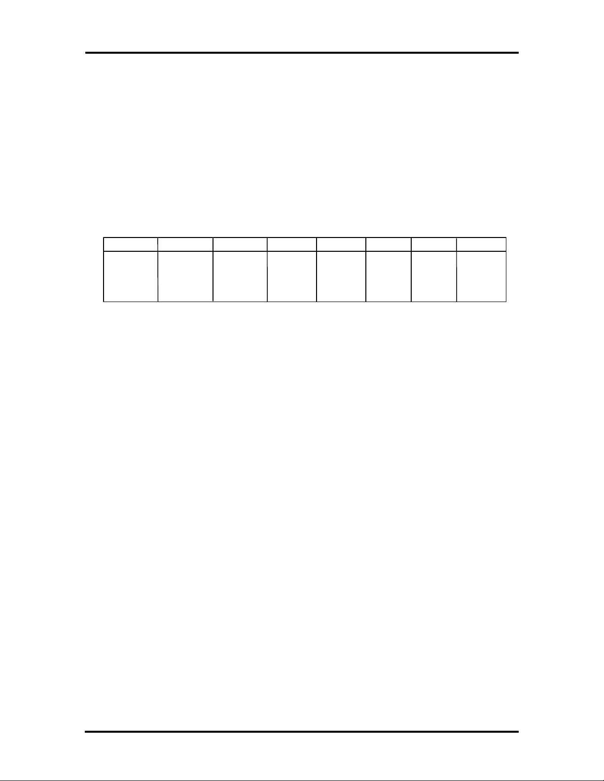
• NEC port 0C13h
0: CMOS Clear (Read only)
Connected to a switch (SW4-1)
0 Requests BIOS to clear CMOS
1 Normal read of CMOS
1: CPU Speed (Read only)
Connected to a switch (SW4-2)
0 equals 60 MHz host bus frequency (default for Image P90E)
1 equals 66 MHz host bus frequency (default for Image P100E)
2: Not Used (Read only)
7
Cache
Module
Present
Bit
Cache
Module
Present
Bit
Cache
Module
Present
Bit
Not used
Not
Used
Not
Used
CPU
0123456
CMOS
Clear
Connected to a switch (SW4-3)
3 and 4: Not Used (Read only)
Page 36
1-20 Technical Information
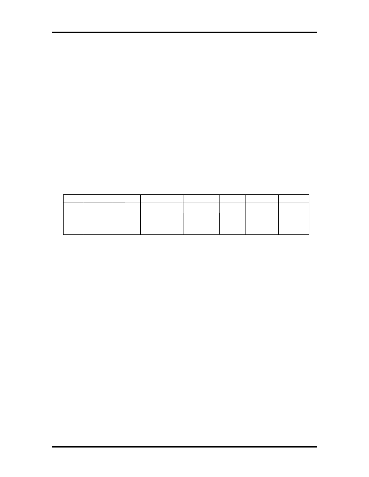
5, 6, and 7: Cache module present bits (Read only)
Bits 7, 6, 5:
0, 0, 0 equals 512 KB synchronous
1, 0, 0 equals 256 KB synchronous
1, 0, 1 equals 256 KB asynchronous
1, 1, 1 equals no cache
All other combinations have no meaning
Keyboard Controller Ports
The 87C42 has a command/status port at I/O address 64h and a read/write register at
address 60h. Commands written to the keyboard controller are written to I/O address 64h.
If the command contains two bytes, the second byte is written to I/O address 64h.
0
Output
Buffer
Full
Parity
Error
Timeout
567
Auxiliary
Buffer
Full
Keyboard/
Auxiliary
Inhibit Switch
34
Command/
Data Flag
System
Flag
12
Input
Buffer Full
The keyboard status register is used to read the status of the keyboard controller. This port
is accessed via Phoenix Technologies, Limited (PTL) extended commands.
Bit 0 Output buffer full
A byte is present in the output buffer when this bit is set.
Bit 1 Input buffer full
A byte is present in the keyboard controller input buffer when this bit is set.
Bit 2 System flag
When this bit is set, the system is in a run time state. When clear (hardware reset), the
system is in a cold boot state. The BIOS uses this bit to sense a hot reset.
Bit 3 Command/data flag
When this bit is set, it indicates the byte in the input buffer is a keyboard controller
command. When clear, it indicates the byte in the input buffer is the data portion of a
keyboard controller command or a command for the keyboard.
Page 37

Technical Information 1-21
Bit 4 Keyboard/Auxiliary inhibit switch
When this bit is set, it indicates that the keyboard and auxiliary device are not inhibited.
The keyboard controller sets bit to 0 when security mode is active.
Bit 5 Auxiliary buffer full
When this bit is set, it indicates that data received from the auxiliary device is present in
the output buffer.
Bit 6 Time-out
When this is set, a time-out has occurred during transmission between the keyboard
controller and the keyboard or auxiliary device.
Bit 7 Parity error
When this bit is set, the last byte received from the keyboard or auxiliary device has an
uncorrectable parity error.
System Memory
Image P90E and Image P100E configurations ship with 16 MB of RAM. System memory
can be expanded to a maximum of 256 MB. Total address space is 4 gigabytes (GB)
maximum. Memory expansion is performed using single in-line memory modules
(SIMMs) installed in SIMM sockets on the memory expansion board.
The memory expansion board consists of eight SIMM connectors organized into four
banks. All system memory supports parity. Memory shipped with the system is comprised
of two 2-MB x 36-bit DRAM SIMM modules (which is 2 x 8MB). The first megabyte
includes the standard 640 KB of base memory. The remaining memory is extended
memory.
The SIMM memory sockets accept 4-, 8-, 16-, or 32-MB SIMM sticks. High-speed RAM
is 32 bits wide with four parity bits. SIMMs are 1 M x 36 bit (4 MB), 2 M x 36 bit (8 MB),
4 M x 36 bit (16 MB), and 8 M x 36 bit (32 MB). There are no switches or jumpers to set
when SIMMs are added.
The system board's eight SIMM sockets are assigned as banks 0, 1, 2, and 3. Each SIMM
kit is inserted into a pair of sockets or bank. Bank 0 contains the two standard SIMMs
shipped with the system. Banks 1, 2, and 3 are available for memory expansion. Different
size SIMMs cannot be intermixed within a bank. See Section 3, Options, for installation
instructions and SIMM memory configurations.
Page 38

1-22 Technical Information
Interrupt Controller
The interrupt controller is implemented on the EISA system component (ESC) and
operates as an interrupt manager for the entire system environment. The controller accepts
requests from peripherals, issues interrupt requests to the processor, resolves interrupt
priorities, and provides vectors for the processor to determine which interrupt routine to
execute. The interrupt controller has priority assignment modes that can be reconfigured at
any time during system operations.
The interrupt levels are listed in Table Section 1-5. Interrupt-level assignments 0 through
15 are in order of decreasing priority. See Section 2, Setup and Configuration, for
information on changing the interrupts using Setup.
Table Section 1-5 Interrupt Level Assignments
Interrupt Priority Interrupt Device
IRQ00 Counter/Timer
IRQ01 Keyboard
IRQ02 Cascade (INT output from slave)
IRQ03 COM2*
IRQ04 COM1*
IRQ05 LPT2*
IRQ06 Diskette Drive Controller*
IRQ07 Parallel Port 1*
IRQ08 Real-time clock
IRQ09 Available
IRQ10 Available
IRQ11 Available
IRQ12 PS/2 mouse*
IRQ13 Coprocessor
IRQ14 Primary IDE
IRQ15 Secondary IDE
*Industry standard locations
Page 39

Technical Information 1-23
Video Controller
The Tseng W32P PCI graphics controller is a PCI local bus video controller that delivers a
32-bit PCI-bus interface with the CPU. It features a graphic user interface (GUI)
accelerator, and advanced features for imaging and multimedia markets. Multimedia and
imaging are enhanced through the inclusion of an unique Image Memory Access (IMA)
port that allows direct access to the frame buffer at high speed. The IMA port allows
analog motion video to be converted to digital video signals. An 8-bit port into memory
allows images to be displayed on screen in real time, at color depths of up to 16.7 million
simultaneous.
Video Memory
There are eight 256k x 8, 45 ns DRAM chips soldered on the system board providing 2 MB
of video memory. The on-board video DRAM provides graphic support for 640 x 480 and
800 x 600 resolutions with 16.8 million colors, 1024 x 768 resolution with 256 colors, or
1280 x 1024 resolution with 16 colors.
EISA Bus
The system board uses the EISA bus for transferring data between the processor and I/O
peripherals and expansion boards. EISA connectors J22 through J25 allow installation of
both EISA and ISA expansion boards. The EISA architecture is fully downward
compatible with ISA hardware, and EISA boards, unlike ISA boards, require no jumper
settings. They are configured through software. A 6264LP 8K x 8 SRAM is used to
configure the EISA bus. This SRAM receives power from the bq4287 RTC, which uses a
lithium battery. Other EISA features include:
n 32-bit memory addressing for the processor, DMA devices, and bus masters
n 8-/16-/32-bit data transfers
n 33 MB/sec burst mode data transfer
n Addressability up to 4 GB
n Efficient synchronous data transfer protocol for normal and high-speed transfers
n Automatic bus cycle translation between EISA and ISA masters and slaves
n Intelligent bus master peripheral controller support
n Enhanced DMA arbitration and transfer rates
n Shareable interrupts, programmable for edge or level triggering
n Automatic system configuration
The four EISA connectors contain two sets of contacts: one for EISA boards and one for
ISA boards. A tab prevents ISA boards from being inserted into the EISA contacts (see
Figure Section 1-3).
Page 40
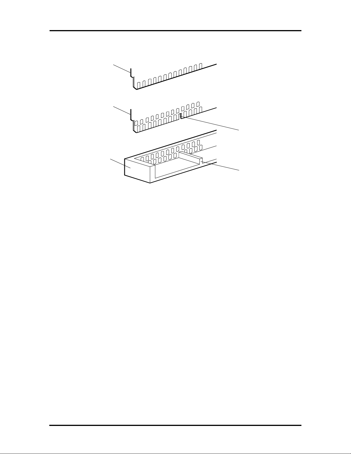
1-24 Technical Information
Tab Notch
EISA expansion slot connector pin assignments are provided in Appendix B.
ISA Expansion
Board
EISA Expansion
Board
EISA Connector
Tab
Figure Section 1-3 EISA Connector
Various DMA cycle types are needed to cover the speed and complex requirements of
different applications. In EISA systems, control signals, address lines, and the data bus use
a bus clock generated by the system board as the transfer reference. Since the bus clock is
not a fixed frequency, the protocol synchronizes the bus cycles to a common clock to
achieve maximum performance.
EISA DMA devices can be programmed for high-performance data transfers using one of
four DMA cycle types. Compatible cycles (the default) supply a higher data transfer than
ISA. The improvement is the result of EISA faster bus arbitration. Type A and type B
cycles permit some ISA-compatible DMA devices to achieve an even higher performance
level. The Burst DMA cycle (type C) provides the highest performance cycle and is only
available to DMA devices designed specifically for Burst. (Burst cycles require 1 clock per
transfer). Table Section 1-6 shows the data transfer rates for each cycle type and the
compatible DMA devices.
Page 41

Technical Information 1-25
Table Section 1-6 DMA Cycles and Compatible DMA Devices
DMA Cycle Transfer
Rate (MB/s)
Compatible
8-bit
16-bit
Type A
8-bit
16-bit
32-bit
Type B
8-bit
16-bit
32-bit
Burst DMA (Type C)
8-bit
16-bit
32-bit
1.0
2.0
1.3
2.6
5.3
2.0
4.0
8.0
8.2
16.5
33.0
Compatible
DMA Devices
All ISA
All ISA
Most ISA
Most ISA
EISA only
Some ISA
Some ISA
EISA only
EISA only
EISA only
EISA only
EISA’s bus master archictecture supports intelligent peripherals. The bus master
architecture provides a high-speed data channel with data rates up to 33 MB per second
using EISA Burst cycles. The bus master provides local intelligence by including a
dedicated I/O processor and local memory. It can relieve the burden on the processor by
performing sophisticated memory access functions, such as non-ordered, scatter-gather
data transfers.
The EISA bus provides a way for EISA expansion boards and ISA-compatible devices to
communicate. EISA data and control signals are generated by the bus master or slave. This
lets the system board copy the data to the appropriate byte lanes and translate the control
signals. Automatic translation is provided by the system board for DMA devices and 16and 32-bit EISA devices.
EISA’s centralized arbitration scheme allows efficient bus sharing among multiple EISA
bus masters and DMA devices. The centralized arbitration supports preemption of an
active bus master or DMA device and can reset a device that does not release the bus after
preemption. The bus is granted to DMA devices, DRAM refresh, bus masters, and
processor functions on a rotational basis. This rotation provides a short latency for DMA
devices to assure ISA compatibility and longer latencies for the bus master and processor.
EISA interrupts can be configured for edge- or level-triggered operation. Edge-triggered
operation supplies compatibility with existing, interrupt-driven ISA devices. Leveltriggered operation allows the sharing of a single system interrupt by many EISA devices.
Page 42

1-26 Technical Information
PCI Local Bus
The industry-standard PCI-bus is a highly-integrated I/O interface that offers the highest
performance local bus available for the Pentium processor. The PCI-bus supports burst
modes that send large chunks of data across the bus, allowing fast displays of highresolution images.
The high-bandwidth PCI-bus eliminates the data bottleneck found in traditional systems,
maintains maximum performance at high clock speeds, and provides a clear upgrade path
to future technologies. PCI expansion slot connector pin assignments are provided in
Appendix B.
PCI Auto Configuration
The system comes with a PCI auto configuration utility that operates in conjunction with
the system’s Setup utility. The utilities automatically configure interrupts, DMA channels,
I/O space, and other parameters to allow addition of PCI boards with minimal intervention.
Parallel Interface
The I/O controller provides a programmable bi-directional printer port that can can be
configured as EPP, ECP, or PS/2 compatible.
The BIOS has automatic EISA printer port sensing. If the BIOS detects an EISA printer
port mapped to the same address, the built-in printer port is disabled. The BIOS also sets
the first parallel interface port it finds as LPT1 and the second port it finds as LPT2. The
interrupt is selected to either IRQ5 or IRQ7 via the Setup.
Interrupt levels for the parallel port are given in Table Section 1-7. Software selectable
base addresses are 3BCh, 378h, and 278h.
Parallel interface signals are output through the system board's 25-pin, D-subconnector.
The connector is located at the rear of the system unit. Pin locations for the parallel
interface connector are shown in Appendix B.
The printer port base address and interrupt request can be independently disabled. It is the
responsibility of the system BIOS to ensure that the base address or interrupt request line
used by a parallel port is not used by the EISA bus (or conflicts will result).
Table Section 1-7 Parallel Port Addressing and Interrupts
Starting I/O Address Interrupt Level Port
278H IRQ05 or 7 LPT1
378H* IRQ05 or 7 (default) LPT1 or LPT2
*Default for parallel port
Page 43

Technical Information 1-27
Serial Interface
The system has two standard serial ports. The serial ports support the standard RS-232C
interface. The interrupt is selectable via Setup. Serial interface signals are output through
the system board's 9-pin, D-subconnector. The connectors are located at the rear of the
system unit. Pin locations for the serial interface connector are shown in Appendix B
Each of the two serial ports can be configured as COM1, COM2, COM3, or COM4. The
options for the base address and interrupt request that can be selected are provided in Table
Section 1-8. The primary serial port (P3) defaults to COM1, IRQ3. The secondary serial
port defaults to COM2, IRQ4. Note that the I/O controller supports the mapping of any of
these logical ports to either physical port. Additionally, each serial port can be
independently disabled. It is the responsibility of the system BIOS to ensure that the base
address or interrupt request line used by a serial port is not used by the EISA bus (or
conflicts will result).
Table Section 1-8 Serial Port Addressing and Interrupts
Base I/O Address
for Serial #1
3F8H (default) IRQ04 (default) or 10
2F8H IRQ03 or 11
3E8H IRQ4 or 10
2E8H IRQ3 or 11
Base I/O Address
for Serial #2
2F8H IRQ3 (default) or 11
3F8H IRQ 4 or 10
3E8H IRQ 4 or 10
2E8H IRQ 3 or 11
*Default for serial port
Serial interface specifications include:
n Baud rate up to 19.2 KB per second
Interrupt Request for
Serial #1
Interrupt Request for
Serial #2
n Word length - 5, 6, 7, or 8 bits
n Stop bit - 1, 1.5, or 2 bits
n Start bit - 1 bit
n Parity bit - 1 bit (odd parity or even parity).
Page 44

1-28 Technical Information
Indicator Panel
The indicator panel is attached to the front panel and contains the power lamp, hard disk
drive busy lamp, and reset button. The indicator panel attaches to the system board using
connector J4 (reset connector), J12 (power lamp connector), and J11 (hard disk drive busy
lamp connector).
Power Supply
The power supply is mounted inside the system unit. It supplies power to the system board
(+5V, +12V, and -12V), and storage devices. In turn, the system board supplies power to
the keyboard, mouse, and any installed expansion boards. (-5V is provided to EISA adapter
boards, but this voltage is not used by the system board.) Three connectors connect the
power supply to the system board (connectors J17, J21, and J31). There are also connectors
available for the six possible storage devices.
A fan inside the power supply (at connectors J6 and J7) provides proper ventilation for the
system. The power supply provides 260W of power. Power requirements and specifications
for the power supply are provided in Appendix A, Specifications.
Diskette Drive
The computer supports up to two diskette drives. Image P90E and Image P100E systems
ship with one standard diskette drive that connects to the system board by means of a
single-connector ribbon cable. To install a second, optional diskette drive, a single ribbon
cable with two drive connectors must be installed in place of the single-connector cable.
The dual-connector cable option is available from NEC (see Section 4). The system refers
to the diskette drives as A and B. Drive A is for the first drive, B is for the second optional
diskette drive. Typically, both diskette drives are terminated. See Section 3, Options, for
instructions on installing an optional 5 1/4-inch diskette drive (or 3 1/2-inch diskette drive
in a 5 1/4-inch form factor). Specifications for the diskette drives are provided in Appendix
A, Specifications.
Hard Disk Drive
The system provides two fast PCI-bus IDE interface connectors on the system board. The
system board supports one or two devices on each IDE connector. The system also
provides one SCSI connector supporting up to five internal and 7 external devices (hard
disk drives, tape back-up drives, and CD ROM readers) using the PCI local bus Fast
SCSI-2 host adapter.
The system unit provides two internal storage slots (one 1-inch height and one 1.6-inch
height) for 3 1/2-inch hard disk drives. When configurations are shipped with a hard disk
drive, one of these slots is occupied. Three accessible 5 1/4-inch device (1.6-inch height)
storage slots also available for optional devices. See Section 3, Options, for installing an
optional hard disk drive. Specifications for the hard drives are provided in Appendix A,
Specifications.
Page 45
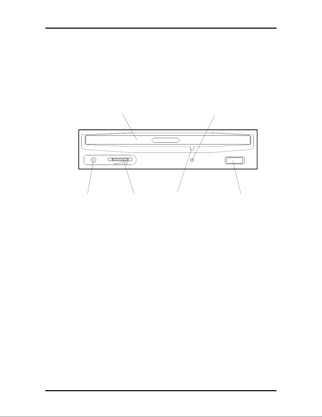
Technical Information 1-29
CD-ROM Reader
All hard disk systems come with the Quad-Speed IDE CD-ROM Reader (assigned as drive
E) installed as standard equipment (see Figure Section 1-4). The CD-ROM reader is a 5
1/4-inch, IDE device that installs in the 5 1/4-inch accessible device slot and cableconnects to the secondary PCI IDE interface connector (J32) on the system board. To add a
CD-ROM reader, see Section 3 for 5 1/4-inch device installation procedures. See Section 4
if you need to remove and reinstall the CD-ROM reader.
Headphone
Jack
KEYBOARD
CD Disc Tray
Volume
Control
Emergency
Eject Screw
Activity
Indicator
Eject
Button
Figure Section 1-4 Quad-Speed IDE CD-ROM Reader
The PS/2-style keyboard is standard equipment for the system. The keyboard provides a
numeric keypad, separate cursor control keys, and 12 function keys, capable of up to 48
functions. Status lamps on the keyboard indicate: Num (Numeric) Lock, Caps (Capital)
Lock, and Scroll Lock key status. The keyboard's six-pin connector is plugged into the rear
of the base unit. The PS/2-style keyboard connector pin assignments are given in
Appendix B, Connector Pin Assignments.
MOUSE
A PS/2-compatible mouse comes standard with your system. A mouse is a hand-held
pointing device used in Windows-based application software. For best result, use the
mouse on a mouse pad.
Page 46

Section 2
Setup and Operation
This subsection provides information on hardware setup for Image P90E and Image P100E
computers. Setup includes unpacking, cabling, and powering up the system. It also includes
configuring the system with the system setup programs. Section 3 provides information for
installing options.
UNPACKING AND REPACKING
Find an area away from devices that generate magnetic fields (electric motors,
transformers, etc.). Place the carton on a sturdy surface, and carefully unpack the system.
The carton contents include the system unit, keyboard, mouse, power cord, user
documentation, and system setup utility diskette(s).
Repack the system using the original shipping carton and packing material. Part numbers
for replacement shipping cartons and packing material are available at the end of Section 4,
Troubleshooting and Repair.
Page 47
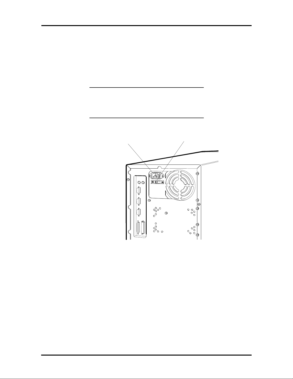
2-2 Setup and Operation
SETUP
Set up the system by making the following connections.
1. At the rear of the system, set the voltage selector switch to 115V or 230V and
insert the power cord into the power socket (see Figure Section 2-1).
CAUTION: The correct AC input voltage must
be properly set. Select the appropriate voltage
with the voltage selector switch located at the
rear of the system.
System Power Socket
Figure Section 2-1 Voltage Selector Switch
Voltage Selector Switch
Page 48
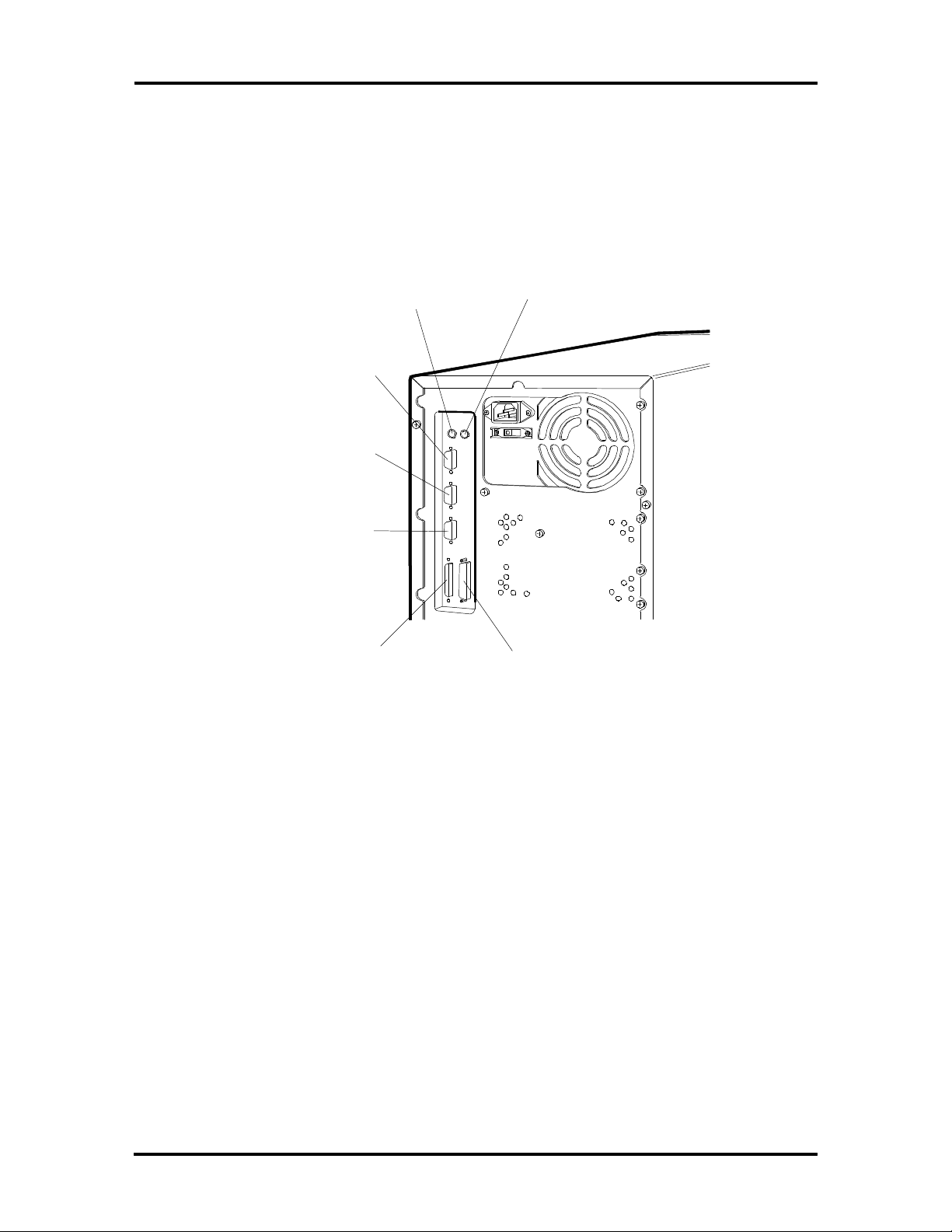
Setup and Operation 2-3
2. Connect the keyboard and mouse cables to the back of the system unit (see
Figure Section 2-2).
3. Connect the monitor and any other peripherals to the rear panel (see Figure
Section 2-2). Detailed monitor connections are given in Section 3, Options.
Mouse Port
Serial Port 1
Serial Port 2
VGA Monitor
Connector
External
SCSI-2
Connector
Keyboard Port
Parallel
Printer Port
Figure Section 2-2 Peripheral Connections
Page 49
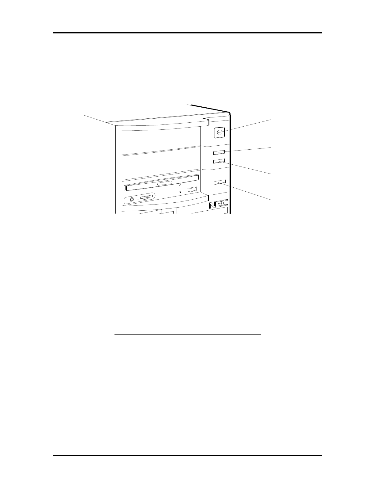
2-4 Setup and Operation
POWER ON
Once any options are installed and the peripherals are connected, press the power button to
power-on the system (see Figure Section 2-3). The user lamps and reset button are also
identified in the figure.
Power
Button
Power
Lamp
Disk
Lamp
Reset
Button
Figure Section 2-3 Indicators, Reset Button, and Power Button
The system has a built-in checking program that automatically tests the components at
power-on. One beep indicates that the system has successfully completed its power-on test.
If there is a problem, a series of beeps may occur. If this happens repeatedly after powering
on the system, power off the system and see Section 4 for troubleshooting.
NOTE: If the system displays a message
indicating that system settings have changed,
run Setup (see “Setting System Parameters”).
If a problem occurs, and is not indicated by beeps, check the following items, then turn to
Section 4 for troubleshooting. Check that:
n the power switch for the system unit and monitor are on.
n all cables and power cords are tightly connected.
n the electrical outlet is working.
n the monitor's brightness and contrast are adjusted properly.
n all options are properly installed (see Section 3 for option installation).
Page 50

Setup and Operation 2-5
SETTING SYSTEM PARAMETERS
This subsection describes the utilities that allow you to view and change system
configuration information and control special features of the system. The utilities include:
n ROM-based Setup utility — use this utility to set system parameters such as date,
time, and system security features. You can also use the utility for configuring
optional PCI and IDE devices or to check or change the video device.
n EISA Configuration utility (ECU) — use this utility when adding, moving,
removing, or configuring any optional EISA, PCI, Plug and Play ISA, or nonPlug and Play ISA expansion boards.
n SCSI Select™ utility — use this utility to check the settings of your installed
SCSI-2 devices or to configure the system for any optional SCSI devices that you
may install.
NOTE: Your system ships from the factory
with the correct system parameters for your
configuration. Unless you add optional
hardware, you do not need to run the Setup,
ECU, or SCSI Select utilities to operate your
system.
However, you might wish to run Setup to set
features that customize your system, such as
time, date, and security. The system ships from
the factory with the correct system configuration
for each system.
System configuration information is stored in nonvolatile memory (NVRAM). Nonvolatile
memory in the system is a complementary metal-oxide semiconductor (CMOS) chip,
backed up by the RTC/battery module on the system board. The RTC battery supplies
continuous power to the CMOS memory and maintains configuration information when
system power is off.
NOTE: NEC recommends that you print out or
write down your current Setup parameters and
store the information in a safe place. This lets
you restore your system to the current parameters
if you ever need to replace the RTC/battery
module (see Section 4 for replacement
procedures).
Page 51

2-6 Setup and Operation
SETUP UTILITY
The Setup utility is used to view and set system parameters. Use the Setup utility program
to:
n set the time and date.
n check or change the diskette drive type.
n update or check system parameters when you add or remove PCI/IDE expansion
options.
n check or change the video device.
n check or update memory cache or shadow settings.
n check or update the system’s boot sequence.
n check or update keyboard settings.
n check the installation of optional memory by comparing the amount of memory
installed with the amount of memory displayed by Setup.
n customize your system with security features such as Supervisor and user login
IDs and passwords.
n correct a hardware discrepancy when the Power-On-Self-Test (POST) displays an
error message and prompts you to run Setup.
n reset system parameters in the event that you need to replace the RTC/battery
module
n reset system parameters after clearing CMOS.
Page 52
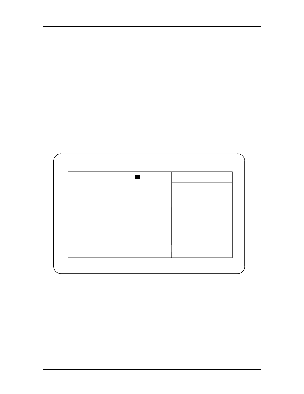
How to Start Setup
To start the Setup utility, follow these steps:
1. Turn on or reboot the system. Setup displays the following message:
F2 to run Setup
2. Press F2 twice as soon as the message is displayed, as it appears only briefly.
Setup’s Main Menu window appears similar to the following screen.
NOTE: The screen shown is typical of the
system. The actual items on the Main Menu
depend upon the hardware installed in the
system.
PhoenixBIOS Setup — Copyright 1985-94 Phoenix Technologies Ltd.
Main Advanced Security Exit
System Time: [ 10 :19:20] Item Specific Help
System Date: [11/12/1994]
Diskette A: [1.44 MB, 3 ½"] <Tab>, <Shift-Tab>, or
Diskette B: [Not Installed] <Enter> selects field.
> IDE Adapter 0 Master: C: 420 Mb
> IDE Adapter 0 Slave: None
> IDE Adapter 1 Master: None
> IDE Adapter 1 Slave: None
Video System: [EGA/VGA]
> Memory Cache:
> Memory Shadow: [Enabled]
> Boot sequence: [A: then C:]
> Numlock: [Auto]
System Memory: 640 KB
Extended Memory: 7 MB
Setup and Operation 2-7
F1 Help ↑↓ Select Item -/+ Change Values F9 Setup Defaults
ESC Exit ←→ Select Menu Enter Select > Sub-Menu F10 Previous Values
How to Use Setup
The Setup utility has a Main Menu window and five top-level menus with submenus.
The Main Menu window contains the following areas:
n A title line — the top line of the Main Menu. This line displays the Setup utility
name and copyright message.
n The menu bar — the line under the Setup title line. The menu bar contains five
top-level menus for setting system parameters.
Page 53

2-8 Setup and Operation
n A Main Menu summary window — the center area on the left side of the screen.
This area provides a summary of Main Menu Setup parameters. Main Menu
parameters can be set directly from this window or from the Main menu option in
the legend bar.
n The Item Specific Help window — the area on the right side of the screen. This
help area provides help information for the Setup option currently selected.
n The legend bar — the area at the bottom of the screen. The legend bar provides a
summary of command keys for using Setup.
n The General Help window — a window that appears any time during Setup after
pressing F2 or Alt H . This help window provides two pages of general
information about using Setup.
The following subsections describe how to use the Main Menu window to set system
parameters.
Menu Bar
The menu bar at the top of the Main Menu window lists these menus:
n Main — Use this menu for basic system configuration. For example, select
“Main” to set the system time, system date, diskette drives, and video parameters.
Use this menu to check memory parameters.
n Advanced — Use this menu to set serial port and printer port addresses and
interrupts, to enable/disable the system’s diskette drive controller and dual-IDE
controllers.
The Advanced menu also provides menu items for setting parity and for setting
parameters for large disks (for example, to use large disks with Windows NT).
Some of the Advanced features are accessible only with a Supervisor password.
n Security — Use this menu to edit and set Supervisor and user IDs and
passwords, set Backup and Virus-check reminders, set network and diskette
access, and enable write-protection for the hard disk.
n Exit — Exits the current menu.
To select an option from the menu bar, use the left and right ←← →→ arrow keys. See “Exiting
Setup” in this section for a description on exiting the Main Menu.
Page 54

Setup and Operation 2-9
Legend Bar
Use the keys listed in the legend bar on the bottom of the Setup menu to make the
selections or exit the current menu. Table Section 2-1 describes the legend keys and their
alternates.
Table Section 2-1 Setup Key Functions
Key Function
F1 or Alt-H Displays General Help window (described later in this section).
Esc Exits the menu.
← or → arrow keys
↑ or ↓ arrow keys
Tab or Shift-Tab Cycles cursor up and down.
Home or End Moves cursor to top or bottom of window.
Page Up or Page Down Moves cursor to next or previous page.
F5 or - Selects the Previous Value for the field.
F6 or + or Space Selects the Next Value for the field.
F9 Loads the Default Configuration values for this menu.
F10 Loads the Previous Configuration values for this menu.
Enter
Alt-R Refreshes screen
n Selecting a Menu Item
Selects a different menu.
Moves cursor up and down.
Executes Command or Selects submenu.
To select a menu item, use the arrow keys to move the cursor to the desired field.
Then use the value keys (F5, –, F6, +, or space bar) to cycle through the value for
that field. The Save Values command in the Exit Menu saves the values currently
displayed in all the menus.
n Displaying a Submenu
To display a submenu, use the arrow keys to move the cursor to the desired
submenu. Then press Enter. A pointer (a right-pointing triangle) marks all
selectable submenus.
Page 55

2-10 Setup and Operation
Item Specific Help Window
The Item Specific Help window on the right side of each menu displays the help text for
the currently selected Setup option. It updates as you move the cursor to each new field.
General Help Window
Pressing F1 or Alt H on any menu brings up the General Help window that describes the
legend keys and their alternates.
The scroll bar on the right of any window indicates that there is more than one page of
information in the window. Use Page Up and Page Down to display all the pages.
Pressing Home and End displays the first and last page.
Press Esc to exit the current window and return to the main menu.
Main Menu Options
Table Section 2-2 lists and describes the available parameters when the Main menu is
selected in the legend bar.
Parameters that can be changed directly from the Main Menu have a right-pointing triangle
next to the parameter. Use the arrow keys to move the cursor to parameter and press Enter
to select a submenu. The remaining parameters have separate submenus and are selected by
pressing Enter
See the subsections following Table Section 2-2 for a description of submenu parameters.
Page 56

Setup and Operation 2-11
Table Section 2-2 Main Menu Parameters
Parameter Options Description
System Time HH:MM:SS Sets the system time. Use the tab key
to move between fields.
System Date MM/DD/YYYY Sets the system date. Use the tab key
to move between fields.
Diskette A:
Diskette B:
IDE Adapter 0 Master* Autotype fixed disk
IDE Adapter 0 Slave* Autotype fixed disk
IDE Adapter 1 Master* Autotype fixed disk
IDE Adapter 1 Slave* Autotype fixed disk
Video System Monochrome
360KB, 5 1/4”
1.2MB, 5 1/4”
720KB, 3 1/2”
1.44MB, 3 1/2” (default A)
2.88MB, 3 1/2”
Not Installed (default B)
Type
Multi-sector transfers
Type
Multi-sector transfers
Type
Multi-sector transfers
Type
Multi-sector transfers
EGA/VGA (default)
CGA 80x25
Selects the type of diskette drive in the
system.
Configures the IDE adapter.
This submenu is described in detail in
the following subsections.
Configures the IDE adapter.
This submenu is described in detail in
the following subsections.
Configures the IDE adapter.
This submenu is described in detail in
the following subsections.
Configures the IDE adapter.
This submenu is described in detail in
the following subsections.
Selects the default video monitor.
Memory Cache* External cache
Cache system BIOS area
Cache video BIOS area
Cache memory regions
Memory Shadow* System shadow
Video shadow
Shadow memory regions
Boot Sequence A: then C: (default)
C: then A:
C: only
NumLock* Auto (default)
On
Off
* Parameter contains submenus.
Enables/disables external cache.
This submenu is described in detail in
the following subsections
Enables or disables video shadow.
This submenu is described in detail in
the following subsections
Selects the drive to boot the operating
system. This submenu is described in
detail in the following subsections
Determines the status of the NumLock
key at power on. This submenu is
described in detail in the following
subsections
Page 57

2-12 Setup and Operation
Table 2-2 Main Menu Parameters (cont’d)
Parameter Options Description
System Memory Automatically detected
by the system
Extended Memory Automatically detected
by the system
IDE Adapters
Displays the amount of conventional
memory detected at power-on.
Displays the amount of extended
memory detected at power-on.
IDE adapters control the IDE devices, such as IDE hard disk drives and IDE CD-ROM
readers, in the system. The system uses two IDE controllers integrated on the system board.
Setup supports up to four IDE devices, with an IDE adapter for each of the following
configurations:
1 Master
1 Master, 1 Slave
2 Masters
2 Masters, 1 Slave
2 Masters, 2 Slaves
The master/slave combination for configurations with an IDE hard disk is “1 Master.” If
adding a hard disk to the primary IDE port, the combination becomes “1 Master, 1 Slave.”
Jumper settings on the IDE device set the device to master or slave (see the documentation
that comes with the device).
Select the IDE Adapter option configuration directly from the Main Menu summary
window. Available options include:
n IDE Adapter 0 Master
n IDE Adapter 0 Slave
n IDE Adapter 1 Master
n IDE Adapter 1 Slave
IDE Adapter 0 configures the primary IDE port, and IDE Adapter 1 configures the
secondary IDE port.
Each IDE Adapter parameter has a right-pointing arrow to the left of it. Selecting the
option displays IDE hard disk parameters. Select an IDE Adapter option and set parameters
for each hard disk separately.
Page 58

Setup and Operation 2-13
Use Table Section 2-3 to configure the hard disk. If the IDE hard disk features auto IDE
type detection, select the Autotype Fixed Disk parameter. The system then automatically
detects the hard disk type and sets the remaining parameters.
Table Section 2-3 IDE Hard Disk Parameters
Parameter Options Description
Autotype Fixed Disk Automatically detected
by the system
Type 1 to 39
User
None
Auto
Cylinders 1 to 2099 Specifies number of cylinders.
Heads 1 to 16 Specifies number of read/write heads.
Sectors/Track 1 to 63 Specifies number of sectors per track.
Write Precomp 0 to 512
None
Multi-Sector
Transfers
LBA Mode Control Enabled (default)
32 Bit I/O Enabled (default)
2, 4, 8, 16,
Sectors
Disabled
Disabled
Pressing Enter causes the system to determne
the hard disk type. If successful, Setup fills in the
remaining fields in this menu and you do not
need to select the disk parameters.
Selecting 1 to 39 fills in all remaining fields with
values for predefined disk type. The User setting
prompts you to fill in the remaining fields. The
Auto setting causes the system to determine disk
geometry at power on.
Specifies number of the cylinder at which to
change the write timing.
Specifies number of sectors in multi-sector
transfers (8 is recommended).
Sets LBA mode control on or off.
Sets 32 bit I/O to on or off.
Transfer Mode Standard
Fast PIO1
Fast PIO2
Fast PIO3
*IDE drives do not require setting Landing Zone and Write Precomp.
Specifies the transfer mode for moving data to
and from the hard disk drive. Standard is the
slowest mode but the most compatible. Fast PIO1
(programmed input/output 1) is the slowest of the
three enhanced modes. Fast PIO3 is the fastest of
the enhancedmodes.
CAUTION: Incorrect settings can cause the
system to malfunction and not be able to read the
drive.
Page 59

2-14 Setup and Operation
Memory Cache
Select “Memory Cache directly from the Main Menu to display the Memory Cache menu
(see Table Section 2-5).
CAUTION: Incorrect settings can cause the
system to malfunction.
Table Section 2-4 Memory Cache Parameters
Parameter Options Description
External Cache Enabled (default)
Disabled
Cache System BIOS Area Enabled (default)
Disabled
Cache Video BIOS Area Enabled (default)
Disabled
Cache Memory Regions
C800 - CBFF
CC00 - CFFF
D000 - D3FF
D400 - D7FF
D800 - DBFF
DC00 - DFFF
Enabled
Enabled
Disabled
Disabled
Disabled
Disabled
Sets the state of the external
memory cache.
Controls caching of system
BIOS area.
Controls caching of video
BIOS area.
Determines configuration of
specified block in upper
memory.
Disabled (default) – shadow
memory not cached for this
region
Enabled – shadow memory is
cached for this region.
Memory Shadow
Select “Memory Shadow” directly from the Main Menu to display the Memory Shadow
menu (see Table Section 2-5).
CAUTION: Incorrect settings can cause the
system to malfunction.
Page 60

Table Section 2-5 Memory Shadow Parameters
Parameter Options Description
System Shadow Not user selectable. Always enabled.
Setup and Operation 2-15
Video shadow Enabled (default)
Disabled
Shadow Memory
Regions
Shadow
Disabled (default)
Always enabled. Shadows video BIOS and improves
performance.
Default is disabled. Shadows optional ROM located in
specified segments of memory and can improve
performance. CAUTION: Some add-in cards, particularly
with on-board firmware, do not work properly when
shadowed. Selecting shadow copies ROMs in this region
to shadow memory.
Boot Sequence
Select “Boot Sequence” directly from the Main Menu summary window to display the
“Boot Sequence” menu.
Use the legend keys to make the selections and exit to the Main Menu. Use Table Section
2-6 to select the boot sequence parameters.
Table Section 2-6 Boot Parameters
Parameters Options Description
Boot sequence A: then C: (default)
C: then A:
C: only
The BIOS attempts to load the operating system
from the disk drives in the sequence selected
here.
Setup prompt Enabled (default)
Disabled
POST errors Enabled (default)
Disabled
Floppy check Enabled (default)
Disabled
Summary screen Enabled (default)
Disabled
Displays “Press <F2> for Setup” during bootup.
At boot error, pauses and displays “Press <F1> to
resume, <F2> for Setup.”
Seeks diskette drives during bootup. Disabling
speeds boot time.
Describes system configuration at the end of
bootup.
Numlock
Select “Numlock” directly from the Main Menu summary window to display the Numlock
and keyboard submenus.
Use the legend keys to make the selections and exit to the Main Menu. Use Table Section
2-7 to configure the keyboard parameters.
Page 61

2-16 Setup and Operation
Table Section 2-7 Numlock and Keyboard Parameters
Parameters Options Description
Numlock Auto (default)
On
Off
Key click Enabled
Disabled (default)
Keyboard auto-
repeat rate
Keyboard auto-
repeat delay
30/sec(default)
26.7/sec
21.8/sec
18.5/sec
13.3/sec
10/sec
6/sec
2/sec
1/4 sec
1/2 sec (default)
3/4 sec
1 sec
On or Off turns NumLock on or off at bootup. Auto
turns NumLock on if it finds a numeric keypad.
Turns audible key click on or off.
Selects key repeat rate.
Sets the delay time after the key is held down
and before it begins to repeat the keystroke.
Page 62

Setup and Operation 2-17
Advanced Menu
Selecting “Advanced” from the menu bar on the Main Menu displays a menu with the
following options:
n Integrated Peripherals
Sets parameters for I/O ports, diskette controller, PCI/SCSI adapter, PCI/IDE
adapter, and monitor type.
n Advanced Chipset Control
Sets PCI parameters
n Plug and Play O/S
Enables or disables the Plug and Play feature.
n PCI Devices
Enables or disables the Combed I/O resource allocation. If enabled, PCI devices
requesting I/O resources are checked for requests.
n Large Disk Access Mode.
Select DOS if using DOS operating system. Select Other if you have UNIX™,
Novell Netware™, or other operating system.
The following subsections describe Advanced Menu options.
NOTE: Accessing the Advanced menu might
require a Supervisor password.
Parameters that can be modified directly from the Advanced menu do not have the rightpointing triangle to the left of the parameter name. These parameters can be modified by
pressing the F5, F6, - or + keys.
Parameters with submenus that are available from the Advanced menu have a rightpointing triangle to the left of the parameter. Use the arrow keys to move the cursor to the
parameter, then press Enter to open the submenu.
See the subsections following the table for a description of Advanced menu parameters and
their submenus.
CAUTION: Setting items in this menu to
incorrect values can cause the system to
malfunction.
Page 63

2-18 Setup and Operation
Integrated Peripherals Menu
Select “Integrated Peripherals” menu on the Advanced Menu to configure the connections
between the system processor and the I/O ports (serial port 1, serial port 2, and the printer
port), the diskette drives, monitor, and VGA feature connector.
NOTE: A Supervisor password may be required
to select Integrated Peripherals menu parameters.
Use the legend keys to make the selections and exit to the Main Menu. Use Table Section
2-8 to configure the peripherals.
Table Section 2-8 Integrated Peripherals Parameters
Feature Options Description
Serial port 1
Serial port 2
Parallel port Disabled
Parallel port
mode
Diskette
controller
Disabled
User-selectable settings
Auto
Defaults:
COM1 3F8, IRQ4
COM2 2F8, IRQ3
378, IRQ 7 (default)
User-selectable settings
Auto
Output only
Bidirectional (default)
EPP
ECP (enabled) – (DMA)
Enabled (default)
Disabled
Selects a unique address and interrupt request
for the listed COM ports. Auto selects the
next available combination.
Use the – and + key to move between fields.
Selects a unique address and interrupt request
for the parallel port. Auto selects the next
available combination.
Sets parallel port mode. Bidirectional is the
default setting.
Enables the on-board diskette drive controller.
Page 64

Table 2-8 Integrated Peripherals Parameters (cont’d)
Feature Options Description
Setup and Operation 2-19
Monitor Type Disabled
DDC Select
Type 1-4 (see
Table Section 2-9)
Disabled
VGA DAC
Broadcast
Disabled
Enabled
Selects the monitor type. Data Channel (DDC)
Select senses capabilities of compatible display
monitors. Non-DDC compatible monitors, types
1 through 4, may also be selected, (see
Table Section 2-9). Type 1 is the default setting.
After selecting DDC or monitor type, you should
use the TLIMODE utility to set the required
resolution.
Select Enabled only when using an option board
that has its own DAC and requires use of the
VGA connector. When enabled, VGA DAC
writes Go to the option board’s DAC, and not to
the onboard VGA’s DAC. Be sure to connect the
monitor to the option board’s video connector.
Table Section 2-9 Monitor Types
Type 1 (Default) Type 2 Type 3 Type 4 Resolution
NOTE: When setting the monitor resolution in Windows, the Auxiliary Windows
Drivers force default refresh rates equivalent to a Type 1 monitor. To obtain the
appropriate refresh rate, use the TLIMODE utility to set the refresh rate
60 Hz 72 Hz 72 Hz 72 Hz 640 by 480 by 16
colors
60 Hz 72 Hz 72 Hz 72 Hz 640 by 480 by
256 colors
56 Hz 60 Hz 72 Hz 72 Hz 800 by 600 by 16
colors
56 Hz 60 Hz 72 Hz 70 Hz 800 by 600 by
256 colors
87 Hz 87 Hz 60 Hz 70 Hz 1024 by 768 by
16 colors
87 Hz 87 Hz 60 Hz 70 Hz 1024 by 768 by
256 colors
— — — 87 Hz 1280 by 1024 by
16 colors
Page 65

2-20 Setup and Operation
Advanced Chipset Control
Select the “Advanced Chipset Control” submenu on the Advanced menu to set PCI
parameters.
NOTE: A Supervisor password might be
required to select parameters from the Advanced
Chipset Control submenu.
Use the legend keys to make your selections and exit to the Main menu. See Table Section
2-10 to configure your peripherals.
CAUTION: Setting items in this menu to
incorrect values can cause your system to
malfunction.
Table Section 2-10 Advanced Chipset Control Parameters
Parameter Options Description
1 MB Memory Gap at
15 MB
CPU to PCI Write
Buffer
PCI to DRAM Write
Buffer
CPU to DRAM Write
Buffer
PCI Memory Burst
Cycles
Latency Timer Value A0 through F0
CAS# Before RAS#
Refresh
Enable
Disable
Enable
Disable
Enable
Disable
Enable
Disable
Enable
Disable
20 through 90
Enable
Disable
If Enabled, turn system RAM off to free
address space for use with option
board. Memory from 15 MB to 16 MB
is disabled, creating 1 MB gap in
system RAM.
Enables CPU to PCI Write Buffer,
allowing data to be temporarily stored in
buffer before writing data.
Enables PCI to DRAM Write Buffer,
allowing data to be temporarily stored in
buffer before writing data.
Enables CPU to DRAM Write Buffer,
allowing data to be temporarily stored in
buffer before writing data.
Enables PCI memory burst write cycles.
Sets maximum number of PCI bus
clocks that PCMC may burst as a
master.
If Enabled, the PCMC uses CAS#
before RAS# timing to refresh DRAM
array. If Disabled, RAS# only refresh
is used.
Burst of 4 Refresh Enable
Disable
If Enabled, refreshes are performed in
sets of four at a frequency of 1/4 of
normal refresh rate. If Disabled, single
refreshes occur at 15.6 ms refresh rate.
Page 66

Setup and Operation 2-21
Table 2-10 Advanced Chipset Control Parameters (cont’d)
Parameter Options Description
0 - Active RAS# Mode Enable
Disable
Parity Error Enable
Disable
DRAM Burst Timing 50 ns DRAMs
60 ns DRAMs
70 ns DRAMs
RAS# Wait State Enable
Disable
CAS# Wait State Enable
Disable
If Enabled, DRAM interface is in 0Active RAS# mode. If Disabled, DRAM
interface is in 1-Active RAS# mode.
If Enabled, parity errors generated
during DRAM read cycles are masked.
If Disabled, parity errors are not
marked.
Selects DRAM burst timing.
If Enabled, one additional wait state is
inserted before RAS# is asserted.
If Enabled, one additional wait state is
inserted before RAS# is asserted.
There is no additional delay between
CAS# assertions.
Plug and Play OS Parameters
The system comes with Plug and Play system support already installed and ready for
installation of a plug and play operating system (O/S). With this support, the system
automatically configures newly added ISA Plug and Play cards. You only need to install
the board and boot the system. The system automatically allocates resources to the board.
Plug and Play boards are industry-standard architecture (ISA) boards with Plug and Play
capability. You can enable Plug and Play directly from the Advanced menu using the
command keys. Selecting “Yes” from the menu enables the Plug and Play option (see
Table Section 2-11). “No” is the default setting, as most current ISA boards do not have
Plug and Play capability. However, you can include them in your system, with or without
Plug and Play capabilities.
To work in a system, boards often use a variety of dedicated resources. If two boards try to
use the same resource, one board might not work or errors may occur.
NOTE: Generally, a resource can be used by
only one board or device. However, some boards
can share the same DMA or IRQ resources.
Review the board manufacturer's documentation
to see if the board supports shared resources.
Page 67

2-22 Setup and Operation
Plug and Play boards are dynamic in nature — the system allocates resources to these
boards upon system boot (Table Section 2-11). Some device drivers support this dynamic
board configuration, but some do not.
Device drivers that do not support the dynamic board configuration are also known as
static device drivers. If using a static device driver, you need to permanently associate
resources assigned with a Plug and Play board, instead of relying on the Plug and Play
default. Otherwise, the device driver might not be able to find the board the next time the
system boots.
Table Section 2-11 Plug and Play Parameters
Parameter Options Description
Plug and Play O/S Yes
No (default)
Selects the Plug and Play feature which
automatically assigns the address and interrupt for
added options. Functions only for Plug and Play
operating systems.
PCI Device Parameters
Select the PCI Devices parameter if you need to allocate I/O resources (see Table Section
2-12). The combed I/O resource allocation parameter default setting is disabled. The
parameter should be enabled only when a non-plug and play board is not working due to
I/O space resource conflicts. This is particuliarly true for older boards using 10-bit I/O
space decoders rather than the full 16-bit I/O space.
Use the legend keys to make your selections and exit to the main menu.
Table Section 2-12 PCI Device Parameters
Parameter Options Description
Combed I/O
Resource Allocation
Enable
Disable
If Enabled, PCI devices requesting I/O
resources are checked: for requests less
than or equal to 256 bytes, that actual I/O
resources are allocated in the first 256
bytes of a 1 KB block of I/O addresses,
and that all PCI to PCI bridges (PPB) have
their ISA Enable bits set.
Note that the BIOS enables Combed I/O
Resource Allocation if it finds a
configurable PCI VGA downstream of a
PPB.
Page 68

Setup and Operation 2-23
Large Disk Access
Select the Large Disk Access Mode parameter when configuring a large disk (see
Table Section 2-13).Use the legend keys to make the selections and exit to the Main Menu.
Table Section 2-13 Large Disk Parameters
Parameter Options Description
Large Disk Mode DOS
Other
Select “DOS” when using DOS. Select other
when using another operating system (such as
UNIX or Novell Netware). If you install new
software and the drive fails, change the
selection (DOS or other) and try again.
A large disk is one that has more than 1024
cylinders, more than 16 heads, or more than 63
tracks per sector.
Security Menu
Selecting “Security” from the Main Menu displays a menu with system security options.
NOTE: The Setup program can be entered with
either a User or Supervisor password. However,
more Setup choices are available with the
Supervisor password.
Parameters that can be modified directly from the Security menu do not have the rightpointing triangle to the left of the parameter name. These parameters can be modified by
pressing the F5, F6, - or + keys.
Parameters with submenus that are available from the Security menu have a right-pointing
triangle to the left of the parameter. Use the arrow keys to move the cursor to the
parameter, then press Enter to open the submenu.
Page 69

2-24 Setup and Operation
See Table Section 2-14 for a description of the security features. Use the legend keys to
make the selections and exit to the Main Menu.
CAUTION: The features that you set in the
Security menu affect the features that appear on
the Security menu as well as on other Setup
menus.
Table Section 2-14 System Security Parameters
Feature Options Description
Edit Supervisor
Information
Allow User Login Yes
Edit User Information See Table Section 2-
Unattended Boot Enabled
Diskette Access User (default)
Fixed Disk Boot Sector Normal (default)
System Backup
Reminder
Virus Check Reminder Disabled (default)
See Table Section 2-
15.
No (default)
15.
Disabled (default)
Supervisor
User Write Protected
Write Protect
Disabled (default)
Daily
Weekly
Monthly
Daily
Weekly
Monthly
Selects security options associated with
supervisor login.
Selecting “Yes” allows a user to login, in addition
to the supervisor.
Selects security options associated with user
login.
Selecting enabled allows the system to enter the
network mode if no login ID is typed within 15
seconds.
Sets access privileges to the diskette drive.
Enables or write protects the boot sector. Write
protect helps prevent viruses. When write
protected, operating systems (and viruses and
application programs) which attempt to modify
the boot sector will not be able to do so.
Sets how often the system backup prompt
appears.
Sets how often the virus scan prompt appears.
Page 70

Setup and Operation 2-25
Edit Supervisor Information Parameters
Select the Edit Supervisor Information submenu from the Security menu to review and set
Supervisor parameters. See Table Section 2-15 for a description of the Edit Supervisor
Information parameters.
Table Section 2-15 Edit Supervisor Information Parameters
Parameter Options Description
Edit Supervisor Login ID (Press Enter)
Edit Supervisor
Password
Minimum Password
Length
Numbers Required in
Password
Password Lifetime 1 to 511 days Sets maximum permitted lifetime of
Minimum Password
Change
Expired Password Life 0 to 127 days Sets maximum period that an expired
(Press Enter)
1 to 14 characters Selects the number of characters
Yes
No
0 to 255 days Sets minimum period between
Pressing Enter allows the Supervisor
to add or change a login ID.
Pressing Enter allows the Supervisor
to add, change, or delete a password.
allowed in the password.
Defines if numbers are required in
password.
password.
password changes.
password may be used.
Pressing Enter at the Edit Supervisor Login parameter on the menu displays a Edit Login
dialog box with the following prompts:
Enter login ID: [ ]
Enter your ID number and press Enter to save the ID.
CAUTION: Passwords and security information
can only be changed on a cold boot.
Pressing Enter at the Edit Supervisor Password parameter on the menu displays an Edit
Password dialog box with the following prompts:
Enter new password: [ ]
Re-enter new password: [ ]
Changes have been saved: [continue]
Type the password and press Enter. Reenter the password and press Enter.
Page 71

2-26 Setup and Operation
Edit User Information Parameters
Select the Edit User Information submenu from the Security menu to review and set user
parameters. See Table Section 2-16 for a description of the Edit User Information
parameters.
Table Section 2-16 Edit User Information Parameters
Parameter Options Description
Edit User Login ID (Press Enter)
Edit User Password (Press Enter)
Minimum Password
Length
Numbers Required in
Password
Password Lifetime 1 to 511 days Sets maximum permitted lifetime of
Minimum Password
Change
Expired Password Life 0 to 127 days Sets maximum period that an expired
1 to 14 characters Selects the number of characters
Yes
No
0 to 255 days Sets minimum period between
Pressing Enter allows the user to
change a login ID.
Pressing Enter allows the user to add
or change a password.
Note: The Supervisor may add,
change, or delete a password. A user
may only add or change a password.
allowed in the password.
Defines if numbers are required in
password.
password.
password changes.
password may be used.
Pressing Enter at the Edit User Login ID parameter on the menu displays a Edit Login
dialog box with the following prompts:
Enter login ID: [ ]
Enter your ID number and press Enter to save the ID.
CAUTION: Passwords and security information
can only be changed on a cold boot.
Pressing Enter at the Edit User Password parameter displays an Edit Password dialog box
with the following prompts:
Enter new password: [ ]
Re-enter new password: [ ]
Changes have been saved: [continue]
Page 72

Setup and Operation 2-27
Enter your password, press Enter, reenter your password, and press Enter to save the
password.
Exit Menu
Selecting “Exit” from the menu bar displays the following exit options:
n Save Changes & Exit
n Discard Changes & Exit
n Get Default Values
n Load Previous Values
n Save Changes.
The following subsections describe each of the options on the Exit Menu. Note that Esc
does not exit this menu. Select one of the items from the menu or menu bar to exit.
Save Changes & Exit
After making the selections on the Setup menus, always select Save Changes & Exit to
save and make them operative.
Unlike standard RAM memory, CMOS is sustained by an onboard battery and stays on
after the system is powered off.
After saving the selections, the program displays this message:
Changes have been saved
[continue]
Pressing Enter at “Continue” exits Setup and reboots your system.
A prompt appears if you attempt to exit without saving.
During bootup, Setup attempts to load the values saved in CMOS. If the values saved in
CMOS cause the system boot to fail, reboot and press F2 to enter Setup. In Setup, the
default values (as described below) can be loaded or you can try to change the values that
caused the boot to fail.
Discard Changes & Exit
Use this option to exit Setup without recording any changes.
Get Default Values
To load all the default Setup values in the Setup menus, select Get Default Values from the
Main Menu. The program displays this message:
Page 73

2-28 Setup and Operation
Default values have been loaded.
[continue]
Pressing Enter at “Continue” exits Setup and reboots your system.
If, during bootup, the BIOS program detects a problem in the integrity of values stored in
CMOS, it displays these messages:
System CMOS checksum bad - run SETUP
Press <F1> to resume, <F2> to Setup
The CMOS values have been corrupted or modified incorrectly, perhaps by an application
program that changes data stored in CMOS.
Press F1 to resume the boot or F2 to run Setup with the ROM default values already loaded
into the menus. Other changes can be made before saving the values to CMOS.
Load Previous Values
During a Setup session, if a mistake has been made and has not yet been saved to CMOS,
the previously saved CMOS values can be restored.
Selecting Load Previous Values on the Exit menu updates all the selections and displays
this message:
Previous values have been loaded!
[continue]
Save Changes
Save Changes saves all the selections without exiting Setup. Other menu selections can be
reviewed or changed.
Selecting Save Changes on the Exit menu saves your changes and displays the following
message:
Changes have been saved
[continue]
Pressing Enter at “Continue” exits Setup and reboots your system.
Page 74

Setup and Operation 2-29
GUIDE FOR CONFIGURING EXPANSION DEVICES
Refer to Table Section 2-17 for a quick reference to configuring optional expansion devices. For details, see the following subsections and the referenced sections and subsections in the table.
Table Section 2-17 Quick Reference to Configuring Expansion Devices
If You Are
Configuring Then
EISA Expansion
Board
2. Load the ECU utility (see “How to Load the ECU” in this section).
3. Read the overview of selecting and configuring EISA or ISA
4. Configure your system and EISA/ISA board (see “Configure
5. Check or change your configuration (see “Configure Computer or
6. Save your changes and exit the ECU utility (see “Configure Computer
PCI Expansion
Device
2. If you need to allocate I/O resources, open the Setup utility (see
3. Load the ECU utility (see “How to Load the ECU” in this section).
1. Install, move, or remove the EISA board in your system (see Section
3 for procedures).
expansion boards (see “Configure Computer or Peripheral Devices Step 1: Important EISA Configuration Information” in this section).
Computer or Peripheral Devices - Step 2: Add or Remove Boards” in this
section).
Peripheral Devices - Step 3: View or Edit Details” in this section).
or Peripheral Devices - Step 5: Save and Exit” in this section).
1. Install, move, or remove the device in your system (see Section 3 for
procedures).
“Setup Utility” earlier in this section). Select “Advanced” from the Setup
utility main menu, and enable the “PCI Devices - Combed I/O Resource
Allocation” parameter from the Advanced menu.
4. Select “Configure Computer or Peripheral Devices” from the ECU
main menu. The system automatically loads PCI configuration
information.
5. Check or change your configuration (see “Configure Computer or
Peripheral Devices - Step 3: View or Edit Details” in this section).
6. Save your changes and exit the ECU utility (see “Configure Computer
or Peripheral Devices - Step 5: Save and Exit” in this section.
Page 75

2-30 Setup and Operation
Table 2-17 Quick Reference to Configuring Expansion Devices (cont’d)
If You Are
Configuring Then
Plug and Play
ISA Board
2. Install the Plug and Play board in your system (see Section 3 for
3. Load the ECU utility (see “How to Load the ECU” in this section).
4. Select “Configure Computer or Peripheral Devices” from the ECU
5. Check or change your configuration (see “Configure Computer or
6. Save your changes and exit the ECU utility (see “Configure Computer
Non-Plug and
Play ISA
Board
2. Configure your system and non-Plug and Play ISA board (see
1. If you have a Plug and Play OS installed, enable “Plug and Play O/S”
in the Setup utility. (See “Setting System Parameters“ earlier in this
section. Select the “Advanced” menu from the Setup main menu and
enable the “Plug and Play O/S” parameter.)
procedures).
Note: do not use the ICU utility or any other utility shipped with the Plug
and Play board. Doing so may cause resource conflicts.
main menu. Your system automatically loads Plug and Play configuration
information.
Peripheral Devices - Step 3: View or Edit Details” in this section).
or Peripheral Devices - Step 5: Save and Exit” in this section).
1. Load the ECU utility (see “How to Load the ECU” in section).
Note: do not install, move, or remove the non-Plug and Play board in
your system until after the configuration procedure is completed.
“Configure Computer or Peripheral Devices - Step 2: Add or Remove
Boards” in this section). Also check the documentation that comes with
the board for resource allocations.
3. Check or change your configuration (see “Configure Computer or
Peripheral Devices - Step 3: View or Edit Details” in this section).
4. Save your changes and exit the ECU utility (see “Configure Computer
or Peripheral Devices - Step 5: Save and Exit,” in this section).
5. Install the non-Plug and Play board in your system (see Chapter 3 for
procedures) and power up the system.
Page 76

Setup and Operation 2-31
Table 2-17 Quick Reference to Configuring Expansion Devices (cont’d)
If You Are
Configuring Then
SCSI-2
Expansion
Device
2. Install the SCSI-2 expansion device in your system (see Chapter 3 for
3. Open the SCSI utility (see the “SCSI Select Utility” subsection at the
4. Select “SCSI Disk Utilities” to review what SCSI devices are currently
5. Select “Configure/View Host Adapter Settings” from the SCSI Select
6. Review the settings of your installed device and reconfigure settings
7. Save your changes and exit the SCSI Select utility.
1. Set switches on the SCSI-2 device to the required settings. (See the
documentation that comes with your device and Section 3 in this guide
for information on setting switches for expansion SCSI-2 devices.)
procedures).
end of this section).
installed and to set the SCSI ID on any optional device you installed.
utility menu (see “SCSI Select Utility” at the end of this section).
as necessary.
Page 77

2-32 Setup and Operation
EISA Configuration Utility
The ECU program comes on a diskette that ships with the computer and is required for
EISA configuration. The ECU provides a detailed view of the system configuration and
allows you to make system configuration changes when you add, move, or remove an
EISA or ISA expansion board.
Use the ECU program when you are setting up the system for the first time and whenever
you add an EISA, ISA, PCI, or Plug and Play ISA board to fully configure the system. This
ensures that the information in the system's complementary metal oxide semiconductor
(CMOS ) is consistent with the configuration information stored in the BIOS.
The ECU
When you add a board to your configuration and run the ECU program, the utility reads
the board’s corresponding configuration (CFG) file. The ECU uses the CFG file, which
describes the characteristics and the required system resources of the board, to create a
conflict-free configuration.
Once you complete the configuration process, configuration information is saved to the
system’s nonvolatile memory for use any time you power-on the system.
The ECU includes the following features:
n Supports EISA and ISA boards, PCI devices, and Plug and Play boards.
n Automatically detects EISA boards, PCI devices, and Plug and Play ISA boards
installed in your computer.
n Helps you configure ISA boards by providing the approprate switch and jumper
settings.
n Creates and maintains the System Configuration Information (SCI) file as a
backup for the computer’s nonvolatile memory.
n Supports configuration (CFG) file extensions.
n Lets you set the computer’s date and time.
The ECU program comes on the EISA Configuration Utility diskette that ships with your
system.
NOTE: Do not execute the EISA Configuration
Utility from your hard disk. The utility program
must start with a cold boot from the EISA Configuration Utility diskette.
Page 78

Setup and Operation 2-33
When to Use the ECU
Run the ECU the first time you set up your system and any time you add, remove, or move
an EISA or ISA board in the computer. You must physically install the boards in the computer and add the configuration information stored in the computer by the ECU.
NOTE: You must install an EISA, PCI, or Plug
and Play board or device before running the
ECU utility. If installing a non-Plug and Play
ISA board, it must be installed after running the
ECU utility.
Use the ECU to :
n change or check system parameters when you add, move, or remove an expan-
sion board.
n print out the required settings of a particular board or option.
n correct a hardware discrepancy when the Power-On Self-Test (POST) displays
an “Invalid EISA Configuration Storage - RUN ECU” error message and
prompts you to run the ECU program.
n boot the system and check parameters when you have a problem booting the
system.
n change functions and resources of boards installed in the system.
n resolve a resource conflict when adding a board or changing a board function or
resource.
n lock and unlock boards in the configuration.
n maintain the ECU Utility diskette.
n set system parameters when the real time clock (RTC)/battery module is re-
placed.
How to Load the ECU
Use the following steps to load the ECU.
1. With the system power off, insert the NEC EISA Configuration Utility diskette
into diskette drive A.
The ECU requires a cold boot each time you load it.
2. Power on the system. After performing its Power-On Self-Test, the system loads
and starts the ECU. An ECU preparation screen appears followed by the NEC
logo screen and the Main Menu (see Figure Section 2-4).
Page 79

2-34 Setup and Operation
Figure Section 2-4 ECU Main Menu
How to Use the ECU
Main Menu
Help
Set Date and Time
Configure Computer or Peripheral Devices
Maintain System Configuration Diskette
Exit
You can use either the keyboard or a mouse to select menu items in the ECU. To use the
ECU, follow the instructions on the screen. Select the “Help” option on the Main Menu for
information about the utility. Information is also available in other menu options by pressing F1 for help.
Be sure to save your changes to set system configuration parameters (see “Exit” in this
subsection).
Read the information in the following subsections for a description of Main Menu options
and how to use them. Options are described in the sequence that they appear on the Main
Menu.
NOTE: For your system configuration, you
might not need to use all of the selections listed
under each Main Menu option. Read the information in the following subsections to select the
options you need.
NOTE: It is strongly recommended that you
make a backup copy of the ECU diskette and
any other diskettes shipped with the computer. If
you do not have a hard disk configuration, make
a backup copy of all other diskettes that ship
with the system. Use the copies and store the
original diskettes.
Page 80

Setup and Operation 2-35
Configure Computer or Peripheral Devices
Select the “Configure Computer or Peripheral Devices” option under the following circumstances:
n you are setting up the system for the first time
n the “Invalid Configuration Information” message appears at power-on.
If this message appears, run the Setup utility to correct any configuration errors.
If you receive an “EISA Configuration NVRAM Bad - Run Configuration utility
- F2 to Run Setup” message, run Setup first, then the ECU utility.
n you add or remove an expansion board
n you installed a PCI, EISA, ISA, or Plug and Play device
n you want to change board functions or resources
n you want to view switch and jumper settings for a specific board
n you replaced the RTC/battery module in the system and need to set the system
parameters.
If you installed an EISA or ISA board and you select “Configure Computer or Peripheral
Devices,” the ECU might display an “Automatic Add” screen with a request for a configuration (CFG) file.
The ECU displays this screen if it needs a configuration (CFG) file for the installed board.
If the screen appears, remove the ECU diskette and insert the diskette containing the CFG
file. Press Enter and follow the screen prompts to automatically add the required CFG file.
NOTE: EISA and ISA boards require CFG files
for system configuration. The board manufacturer supplies the CFG file for an EISA board.
Some ISA boards also come with a CFG file. If
you have an ISA board that does not have a CFG
file, see “ISA Boards without CFG Files” in this
section.
If the ECU does not need any configuration files, it displays a menu with five steps for
configuring your computer:
Step 1: Important EISA configuration information — provides EISA configuration information.
Step 2: Add or remove boards — configures the system for the addition or removal of an
expansion board to or from the system.
Page 81

2-36 Setup and Operation
Step 3: View or edit details — lets you view and change system board settings. You must
select this step when you are setting up the system for the first time.
Step 4: Examine switches or print report — allows you to view the required switch and
jumper settings of a particular board. You can also select a print option to print the
required settings of a particular board.
Step 5: Save and exit — lets you save the system configuration and exit the utility.
NOTE: If you are setting up the system for the
first time, you must select Step 3, even if you did
not install an expansion board. This step configures the system board in your system.
The following subsections describe each of the configuration steps in sequence.
(1) Step 1: Important EISA Configuration Information
Select Step 1 for information about using the ECU to configure your EISA system.
NOTE: It is recommended that you select Step
1 before continuing with the ECU utility. Step 1
contains an overview of the process for selecting
and configuring EISA or ISA expansion boards.
Page 82

Setup and Operation 2-37
(2) Step 2: Add or Remove Boards
Select Step 2 whenever you install or remove any EISA boards or ISA boards with CFG
files from the system.
NOTE: If you are adding a EISA board to your
system, first install the board. Then run the ECU
and select Step 3: Configure Computer and
Peripheral Devices. This step automatically
loads configuration information and adds the
EISA board to your system configuration. If you
are installing a non-plug and play ISA board, install the board after running the ECU and performing steps 2 through 5.
When you select Step 2, a screen displays the system board and any EISA boards currently
installed in your system. The display includes board names and expansion slot numbers.
NOTE: Integrated on-board PCI SCSI, IDE,
and VGA controllers are listed as “Embedded”
controllers at the bottom of the list of expansion
slots. You cannot move or remove an embedded
feature, but you can enable or disable the feature
(see “Step 3: View or Edit Details”).
To complete the Step 2 configuration process, use the following steps.
1. Select “Step 2: Add or remove boards” from the Configure Computer or Periph-
eral Devices menu. Press Enter.
A screen displays the boards installed in your system and the available expansion
board slots. Scroll through the list of boards displayed and proceed as follows.
n If the list shows all your boards installed, press F10.
NOTE: If a CFG file comes with your board
and a CFG file already exists on the ECU diskette, you still need to copy the CFG file from the
option configuration diskette (see “Maintain
System Configuration Diskette” in this section).
This ensures that the the system uses the latest
version of the file.
Page 83

2-38 Setup and Operation
In the rare event that the CFG file on the ECU
diskette is newer, the system displays an OverWrite Current File message. In this case, press
Esc to cancel.
n If a board is not displayed and you did not load a configuration file for it, go
to the next step.
NOTE: You cannot use the next step to add
ISA boards without configuration files. To add
an ISA board without configuration files, see
“ISA Boards without CFG Files.”
2. Highlight the slot location of the installed board and press Insert to add the board.
The Add screen appears.
3. Remove the ECU diskette from the diskette drive and insert the diskette with the
board's CFG file.
4. Press Enter. The Add configuration (CFG) file screen appears.
5. Press F7 and press Enter to change to the drive containing the CFG file.
Page 84

Setup and Operation 2-39
NOTE: If a CFG file comes with your board
and a CFG file already exists on the ECU diskette, you still need to copy the CFG file from the
option configuration diskette (see “Maintain
System Configuration Diskette” in this section).
This ensures that the system uses the latest version of the file.
In the rare event that the CFG file on the ECU
diskette is newer, the system displays an OverWrite Current File message. In this case, press
Esc to cancel.
6. Select the file you want to add and press Enter. A screen with information about
the board appears.
7. Press Enter to confirm the addition of the board.
8. Insert the ECU diskette. Highlight the board and press Enter to confirm the slot
location of the board.
9. When you are done, press F10 to exit the “Step 2: Add or remove boards” con-
figuration procedure.
Before you exit, note information you might need to change settings or install
boards. To print out any configuration information about the board, select “Step
4: Examine Required Switches.”
Repeat steps 1 through 9 in the above procedure to add another board.
(3) Step 3: View or Edit Details
Select Step 3 to configure your system when you are setting up the system for the first time
and to modify system board settings.
System board settings include the following configuration categories:
n System and video BIOS caching and system and video BIOS shadowing
n Port configurations — parallel port, serial port 1, and serial port 2 addresses and
interrupts.
n Peripheral controllers — diskette drive controller, PCI SCSI controller, PCI IDE
controller, PCI VGA controller.
Refer to Table Section 2-18 for a quick-reference list of EISA Configuration Utility parameters and their factory (default) settings.
See the procedure and additional information in Table Section 2-18 to configure your system board.
Page 85

2-40 Setup and Operation
Table Section 2-18 EISA Configuration Utility
MENU/PARAMETER DEFAULT SETTING
Parameters
EISA NMI Control
Software NMI
32-bit Bus Timeout NMI
Parallel Port
Parallel Port Mode
Serial Port 1
Serial Port 2
Diskette Controller
Cache Video BIOS area
Cache Memory Region (800)
Cache Memory Region (CC00)
Cache Memory Region (D000)
Cache Memory Region (D400)
Cache Memory Region (D800)
Cache Memory Region (DC00)
Shadow Video BIOS area
Shadow Memory Region (800)
Shadow Memory Region (CC00)
Shadow Memory Region (D000)
Shadow Memory Region (D400)
Shadow Memory Region (D800)
Shadow Memory Region (DC00)
Enabled
Enabled
Port 3F8 IRQ 7
Bidirectional
Port 3F8 IRQ 4
Port 2F8 IRQ 3
Enabled
Enabled
Enabled
Enabled
Disabled
Disabled
Disabled
Disabled
Enabled
Disabled
Disabled
Disabled
Disabled
Disabled
Disabled
Embedded — PCI SCSI Controller
Adaptec 7850 PCI SCSI Controller
Embedded — PCI IDE Controller
CMD 640B PCI IDE Controller
Standard IDE Resources
Embedded — PCI VGA Controller
Tseng ET4000 W32P (D) PCI VGA Controller
Standard VGA Resources
Disabled (enabled
for SCSI hard drive
configurations)
Enabled (for IDE
configurations only)
Enabled (for IDE
configurations only)
Enabled
Enabled
Page 86

Use the following procedure to configure the system board.
NOTE: See the guidelines that follow the pro-
cedure for additional information about setting
system parameters.
1. Select “Step 3: View or edit details” from the Configure Computer or Peripheral
Devices menu and press Enter.
A screen appears with the configuration categories and their parameters.
2. Scroll through the list using your arrow keys or Page Up and Page Down keys to
view the parameters.
To view parameter choices, highlight the parameter and press Enter.
3. Make any parameter changes. To view, and in some cases, to edit parameter re-
sources (for example, interrupts, I/O addresses, or I/O ports), press F6.
Setup and Operation 2-41
4. When you are through viewing and changing parameter settings, press F10 to exit
the “Step 3: View or edit details” procedure.
NOTE: Print options for printing the required
settings of a particular board or option are available through Step 4 on the Configure Computer
or Peripheral Devices menu (see “Step 4: Examine Required Switches” later in this subsection).
Advanced menu
Press F7 to use Advanced menu functions for setting system parameters. Ad-
vanced menu functions are briefly described as follows.
n Lock/unlock boards — provides options for securing or unlocking the settings of
a board or the entire system. Securing the settings prevents changes to the current
settings.
Page 87

2-42 Setup and Operation
NOTE: You must lock an ISA board config-
ured as a Generic ISA Adapter board (ISA board
without CFG files) to reserve the selected system
resources. Locking the board prevents the ECU
from using the selected resources to resolve
resource conflicts.
Locking system resources for a Generic ISA
Adapter board can cause changes to the switch
and jumper settings of other boards in the system.
n View additional system information menu — provides the following submenu to
display detailed information about system specifications and resources:
Board specification
System specification
Used resources
Available resources
n Set verification mode menu — allows you to specify whether the computer's con-
figuration must be checked each time you make a change or only when you
choose.
NOTE: Selecting “Manual Mode” may cause
conflicts that prevent the system from booting.
n Maintain SCI files menu — provides options regarding System Configuration In-
formation (SCI) files.
PCI IDE Controller
If you installed an IDE hard disk in the system, locate the “Embedded PCI IDE
controller” on the system board list of details and enable “Standard IDE Resources.”
Page 88

Setup and Operation 2-43
NOTE: Enabling the IDE controller automati-
cally changes any installed SCSI controller to a
secondary controller and might change the IRQ.
If you have an IDE hard disk, you must also run
the Setup program at power-on to set the drive
parameters.
PCI SCSI Controller and SCSI Termination
If you have a SCSI device installed in the system, check that the Embedded PCI
SCSI Controller (Adaptec 7850) parameter is enabled (see Table Section 2-18).
If you have both internal and external SCSI devices installed and connected to
the on-board SCSI-2 host adapter, use the SCSI Setup Utility program to set
“External” SCSI device termination. Run the SCSI Setup Utility when you complete the system configuration with the ECU (see “SCSI Setup Utility” later in
this section).
Shadowing and Caching Features
The shadowing and caching features should be left enabled.
(4) Step 4: Examine Required Switches
Select Step 4 to view any required switch and jumper settings on installed boards. To view
the required settings, highlight the board you wish to view, and press Enter.
NOTE: To check the current settings of a
board, you must physically verify the settings.
For example, you must power off the system and
remove the system cover to verify the current
system board System Configuration Switch
(SW4) settings Switch setting information is
provided at the end of this section.
If you have a printer set up, you can print the settings of a particular board or option. You
can also save the settings to a file that you can use to print on another computer that is
connected to a printer. Press F7 for a list of print options.
(5) Step 5: Save and Exit
Select Step 5 to save your configuration and reboot your system.
Page 89

2-44 Setup and Operation
Set Date or Time
Set the date and time if you are setting up the system for the first time or you need to correct the settings. The settings remain in memory even after the system is powered off.
To set the date and time, choose “Select Date or Time” from the Main Menu and select the
date and time menu options.
To set the date, type the current day, month, and year in dd-mm-yyyy format. Press Enter.
To set the time, type the current hour, minute, and seconds in hh:mm:ss, 24-hour format.
For example, type 13:30:00 for 1:30 p.m. and press Enter.
NOTE: When setting the date or time, enter any
preceding zeroes. For example, to enter 8:20
a.m. and March 7, 1995, type 08:20:00 and 03-
07-1995.
To cancel the selection without saving the date and time, press Esc.
Maintain System Configuration Diskette
Select this option to create, load, copy, or delete any necessary system configuration information (SCI) files. You can also use this option to copy and delete configuration (CFG)
files.
Depending on the system configuration, you might want to modify the system board SCI
file. Before configuring the system, you must copy configuration files for the EISA boards,
and in some cases, ISA boards. This subsection provides copying procedures for both.
CFG files are required to correctly configure EISA boards. Every EISA board contains
settings that determine how the board works within the system. These settings are in a configuration file and are copied to and stored in the system.
All EISA boards should come with CFG files. If not, check the configuration files that
come on the ECU diskette or contact the EISA board manufacturer to obtain the appropriate files. If your ISA boards did not come with a CFG file, see “ISA Boards without CFG
Files” in this section.
Page 90

Use the following steps to copy or update configuration files.
1. Select “Maintain System Configuration Diskette” from the Main Menu.
2. Remove the ECU diskette from the diskette drive and replace it with the configu-
ration diskette that came with the option board.
3. Select “Copy/update CFG files” from the menu.
4. Press Enter. A screen appears showing the availableconfiguration files available.
5. Select the configuration file you need to copy. You can only copy one file at a
time. Press Enter.
You are prompted to remove the configuration diskette.
6. Remove the diskette and replace it with the ECU diskette.
After replacing the diskette, the CFG file is copied onto the ECU diskette.
7. Repeat Steps 5 and 6 to copy all the configuration files you need onto the ECU
diskette.
Setup and Operation 2-45
Exit
Select this option to exit the EISA Configuration Utility.
If you are setting up the system for the first time and you have a SCSI device (such as a
SCSI hard disk), see “SCSI Setup Utility” later in this section.
PCI Devices and Plug and Play ISA Boards
Whenever you install a PCI device or Plug and Play ISA board in the system, run the ECU
and select “Configure Computer or Peripheral Devices.”
This configuration procedure automatically loads configuration information and adds the
PCI device or Plug and Play board to the configuration. Select “Step 3: View or Edit Details” to check system parameters and “Step 4: Examine Required Switches” to print out
system configuration information.
Be sure to select Step 5 in the Configure Computer or Peripheral Devices menu and save
your configuration.
Page 91

2-46 Setup and Operation
ISA Boards without CFG Files
If a CFG file did not ship with your ISA board, check to see if one exists for the board on
the ECU diskette or on a CFG File Library diskette. If you still cannot locate a CFG file for
the board, use one of the following procedures:
n configure your system for the ISA board with the Generic ISA CFG File pro-
vided by the ECU (see the next subsection, “Using the Generic ISA CFG File”).
n create a CFG file for the ISA board (see “Using the Create CFG File Facility”
later in this section). Use this procedure when the Generic ISA CFG File is not
available.
(1) Using the Generic ISA CFG File
The ECU provides one Generic ISA CFG file that you can use with an ISA board that does
not have a corresponding file. However, if you have a multifunction ISA board, you may
have to manually create a configuration file (see “Using the Create CFG File Facility”).
NOTE: The ECU provides only one Generic
ISA CFG file. If you already used the Generic
ISA CFG file, see the next subsection, “Using
the Create CFG File Facility.”
Before you use the Generic ISA CFG file, determine if a CFG file exists for the ISA board.
If you cannot locate a CFG file, use the following procedure to configure your system for
the ISA board.
NOTE: Do not install the ISA board in the
computer until you have completed the following procedure.
1. Locate the manufacturer’s documentation that comes with the ISA board. This
document provides information about any required resources for the ISA board.
2. Run the ECU utility and select “Configure Computer or Peripheral Devices”
from the Main Menu.
3. Select “Step 2: Add or remove boards.”
4. Press Insert to select the Add function. A message appears telling you to locate
the CFG file for the board you want to install.
5. Press Enter. The “Select a Configuration (CFG) file to add” screen appears.
Page 92

Setup and Operation 2-47
6. Select “Generic ISA Adapter” and press Enter. The “Add confirmation” screen
appears with the manufacturer’s comments and instructions to configure the
board resources manually.
7. Read the manufacturer’s comments and press Enter when you are finished. The
“Add” screen apprears.
8. Select the slot in which you want to install the ISA board and press Enter. The
“Step 2: Add or remove boards” screen appears and shows the addition of the
Generic ISA Adapter.
NOTE: You can select any available slot.
Available slots are listed in the order of preference.
9. Press F10. The “Steps in configuring your computer” menu appears.
10. Select “Step 3: View or edit details.” Scroll through the menu items until you
find the Generic ISA Adapter board.
11. Using the information provided by the board manufacturer, select the appropri-
ate Generic ISA Adapter board function.
For example, if the board requires an IRQ setting, select “ISA IRQ Resource
Allocation.” Press F6 to edit the resource.
When you are done editing the resource, press F10.
12. Repeat step 11 for each function on the Generic ISA Adapter board. When you
are through editing the functions, press F7 to select the Advanced menu.
13. Select “Lock/unlock boards.” Then select the Generic ISA Adapter board from
the list. An exclamation point next to the board indicates that it is locked.
NOTE: Locking the Generic ISA Adapter
board reserves the selected system resources
and prevents the ECU from using them to resolve resource conflicts.
Page 93

2-48 Setup and Operation
NOTE: Do not remove a locked board after it is
locked and saved and after you have exited from
the ECU utility. You must unlock any added
boards before removing the board from the system. Otherwise, system resources may change,
causing ECU problems. If this occurs, you must
clear the CMOS using the System Configuration
Switch (SW4). Switch setting information is
provided at end of this section.
14. Complete the Step 3 configuration as follows.
n Press F10 to select Done. The Advanced menu appears.
n Press Esc. The “Step 3: View or edit details” screen appears.
n Press F10 to select Done. The “Steps in configuring your computer” screen
appears.
15. Select “Step 4: Examine switches or print report.” Identify any boards on the
screen marked with an arrow.
An arrow indicates that the boards might have jumpers and switches that you
must physically verify or that a software statement with additional information
about the board is provided.
NOTE: Locking system resources for the Ge-
neric ISA Adapter board can cause changes to
the switch and jumper settings of other boards in
the system.
16. Press F7 to select a print option to print the configurations of the boards marked
with an arrow. If you do not choose a print option, be sure to write down switch
and jumper information provided for the boards marked with an arrow.
17. Press F10. The “Steps in configuring your computer” screen appears. Select
“Step 5: Save and Exit.”
18. Select “Save the configuration and restart the computer.” At the “Reboot”
screen, press Enter.
19. Remove the ECU diskette and turn off the system. If you printed any configura-
tion settings to a file, install the diskette in a computer attached to printer so you
can print a hard copy.
Page 94

Setup and Operation 2-49
20. Compare the settings of the boards installed to the printout. Make any changes
necessary. The settings on the board(s) must match the settings on your printout
for the system to operate correctly. You might need to remove a board to access
its switches and/or jumpers.
21. If you removed any boards to change settings, reinstall the boards in the com-
puter.
22. Install the ISA board (see Section 3 in this manual).
(2) Using the Create CFG File Facility
Use the “Create CFG File Facility” when you cannot locate the CFG file for a particular
board and the Generic ISA configuration (CFG) file is not available. Use the following
procedure.
1. Run the ECU and select “Configure Computer or Peripheral Devices” from the
Main Menu.
2. Select “Step 2: Add or remove boards.”
3. Press Insert to select the Add function. A message
appears telling you to locate the CFG file for the board you want to install.
4. Press Enter. The “Select a Configuration (CFG) file to add” screen appears.
5. Press F5 to select “Not Listed.” The “Add a board without a CFG file” screen ap-
pears.
6. Select “Look for CFG file.” The “Look for CFG file” screen appears. Read
through the information and press Enter when done. The “Add a board without a
CFG file” screen reappears.
7. Select “Create CFG file.” The “Create a Board CFG File” screen appears.
8. Enter the board description and manufacturer. Press Enter. The “New Board
Setup” screen appears.
9. Review the manufacturer’s documentation and select the resources used by the
board’s current configuration as follows:
n If your board requires interrupts, choose “Select Interrupts.” Select the inter-
rupts used by the board’s current configuration. You must limit your selections to seven interrupts.
Press F10 when done. The “New Board Setup” screen reappears.
NOTE: Press F7 if you need to check the current
allocation of your system’s resources.
Page 95

2-50 Setup and Operation
n If the board requires DMA channels, choose “Select DMA Channels.” Select
the DMA channels used by the board’s current configuration. You must limit
your selections to four DMA channels.
Press F10 when done. The “New Board Setup” screen reappears.
n If the board requires a port address, choose “Select Port Addresses.” The
“Select Port Addresses” screen appears. Press Insert to enter a port address or
Delete to remove a port address. When you press Insert, the “Add New Port”
screen appears.
Enter the starting and ending addresses in hexadecimal format. Press Enter
when you are done. The “New Board Setup” screen appears.
n If the board requires a memory address, choose “Select Memory Addresses.”
The “Select Memory Addresses” screen appears. Press Insert to enter a memory address or Delete to remove a memory address. When you press Insert,
the “Add New Memory” screen appears.
Enter the starting address in hexadecimal format and the length of the address
in kilobytes. Press Enter when you are done. The “Select Memory Addresses” screen appears.
You can add or delete another memory address. You must limit your selection to nine memory addresses. Press F10 when you are done. The “New
Board Setup” screen reappears.
10. Press F10 when you finish selecting the resources used by the board. The “View
Current Settings” screen appears. Press Enter to save the current settings. The
“Add confirmation” screen appears.
11. Read the manufacturer’s comments and press Enter when you are done. The
“Add” screen appears.
12. Select the slot in which you want to install the board. Press Enter. If you add a
board with a tag such as “video,” it must be installed in a slot with an identical
tag. Otherwise, select any available slot.
NOTE: If the board causes a conflict in the
configuration, a Caution message appears with
instructions to remove the conflict; otherwise,
the system may hang-up.
13. Press F10 when the “Step 2: Add or remove boards” screen appears. The “Steps
in configuring your computer” screen appears.
Page 96

Setup and Operation 2-51
14. Complete the configuration as follows:
n Select “Step 4: Examine switches or print report.” Note any boards marked
with an arrow on the screen.
The arrows indicate that the board might have jumpers and switches that you
must physcically verify or that a software statement provides additional information about the board.
n Press F7 to select a print option to print the configurations of the boards
marked with an arrow. If you do not choose a print option, be sure to write
down switch and jumper information provided for the boards marked with an
arrow.
n Press F10. The “Steps in configuring your computer” screen appears. Select
“Step 5: Save and Exit.”
n Select “Save the configuration and restart the computer.” At the “Reboot”
screen, press Enter.
15. Turn off the system and remove the ECU diskette. If you printed any configura-
tion settings to a file, install the diskette in a computer attached to the printer so
you can print a hard copy.
16. Compare the settings of the boards installed to the printout. Make any changes
necessary. The settings on the board(s) must match the settings on your printout
for the system to operate correctly. You might need to remove a board to access
its switches and/or jumpers (see Section 3 in this manual).
17. If you removed any boards to change settings, reinstall the boards in the com-
puter (see in Section 3 in this manual).
18. Install the ISA board (see Section 3 in this manual).
SCSI Select Utility
The SCSI Select utility allows you to check your installed SCSI devices and to configure
the SCSI host adapter if you install optional SCSI devices.
To enter the SCSI Select utility, press Ctrl A at your system’s opening screen.
NOTE: You must press Ctrl A as soon as the
following message appears on the screen.
<<<Press <Cntrl> <A> for SCSI Select (tm) Utility>>>
A screen similiar to the following appears.
Page 97

2-52 Setup and Operation
Adaptec AIC7850 <SCSISelect (tm) > Utility V1.11
Would you like to configure the host adapter, or run the
SCSI disk utilities? Select the option and press <Enter>
Press <F5> to switch between color and monochrome modes.
AIC-7850 at Bus:Device 00:03h
Options
Configure/View Host Adapter Settings
Arrow keys to move cursor, <Enter> to select option, <Esc> to exit (*= default
SCSI Disk Utilities
See the following subsections for a description of the Configure/View Host Adapter Settings option and the SCSI Disk Utilities option.
Configure/View Host Adapter Settings
The Configure/View Host Adapter option allows you to review the settings of your installed SCSI devices and to reconfigure the settings if you install optional SCSI devices.
At the SCSI Select utility opening screen, position the cursor to Configure/View Host
Adapter Settings and press Enter to display the Configure/View Host Adapter menu. A
screen similar to the following displays.
NOTE: The screen shown is typical of your
system. The actual items on the menu depend
upon the hardware installed in your system.
AIC-7850 at Bus Device 00:03h
Configure/View Host Adapter Settings
SCSI Bus Interface Definitions
Host Adapter SCSI ID ......................... 7
SCSI Parity Checking .......................... Enabled
Host Adapter SCSI Termination .......... Enabled
Additional Options
SCSI Device Configuration .................. Press <Enter>
Advanced Configuration Options ......... Press <Enter>
<F6> - Reset to Host Adapter Defaults
Arrow Keys to Move Cursor, <Enter> to Select Option, <ESC> to Exit (*=default)
For the SCSI Bus Interface Definitions settings, use the arrow keys to move the cursor to
the parameter, press Enter to change the setting, and press Esc to exit. Press F6 to reset to
the Host Adapter defaults.
Page 98

Setup and Operation 2-53
Pressing Esc displays the following:
Save Changes Made?
Yes
No
Selecting No takes you back to the Options screen. Selecting Yes saves your changes and
reboots your system after you press any key when the following message is displayed:
Please Press any Key to Reboot
For the Additional Options settings, use the arrow keys to move the cursor to the parameter, press Enter to display the option’s submenu, make your changes, and press Esc to exit.
Press F6 to reset to the Host Adapter defaults.
Table Section 2-19 summarize the SCSI Device Configuration Option, and Table Section
2-20 summarizes the Advanced Configuration Option submenu parameters.
Table Section 2-19 SCSI Device Configuration Options
PARAMETERs Options Description
Initiate Sync
Negotiation
Maximum Sync
Transfer Rate
Enable
Disconnection
Note: The following options have no effect if the BIOS is disabled.
Sent Start Unit
Command
Include in BIOS
Scan
Yes (default)
No
10.0 (default)
8.0
6.7
5.0
Yes (default)
No
Yes (default)
No
Yes (default)
No
Enables or disables the sync
negotiation for each SCSI
device.
Sets maximum sync transfer rate
for each SCSI device.
Enables or disables the SCSI
device.
Enables or disables the motor
start command for each SCSI
device.
Enables or disables the BIOS
scan function.
Page 99

2-54 Setup and Operation
Table Section 2-20 Advanced Configuration Options
Parameters Options Description
Reset SCSI Bus at
IC Initialization
Note: The following options have no effect if the BIOS is disabled.
Host Adapter BIOS Enable (default)
Support Removal
Disks under BIOS
at Fixed Disks
Extended BIOS
Translations for Drives
Greater than 1 GByte
BIOS Support For
More Than 2 Drives
(MS-DOS 5.0 and
above)
Enable (default)
Disable
Disable
Boot Only (default)
All Disks Enabled
Enable (default)
Disable
Enable (defualt)
Disable
Enables or disables the Reset
SCSI Bus at Initialization.
Enables or disables the host
adapter BIOS
Allows use of removable hard
disks as fixed hard disk under
BIOS control.
Enables or disables extended
BIOS support for 1-GB or larger
drives.
Enables or disables BIOS support
for more than two drives.
SCSI Disk Utilities
Use the SCSI Disk Utilities option to check what SCSI devices are currently installed in
your system and to set the SCSI ID number on any optional SCSI devices that you may install.
At the SCSI Select utility opening screen, position the cursor to SCSI Disk Utilities and
press Enter to display the SCSI Disk Utilities menu.
Before opening the menu, the utility scans your system for installed SCSI devices as indicated by a Scanning message on your screen.
On completion of the scan, a screen similar to the following displays.
NOTE: The screen shown is typical of your
system. The actual items on the menu depend
upon the hardware installed in your system.
Page 100

Setup and Operation 2-55
AIC-7850 at Bus Device 00:03h
Select SCSI Disk and Press <Enter>
SCSI ID #0:Seagate ST3255ON
SCSI ID #1 No device
SCSI ID #2 No device
SCSI ID #3 No device
SCSI ID #4 NEC CD-ROM Drive
SCSI ID #5 No device
SCSI ID #6 No device
SCSI ID #7 AIC-7850
Arrow Keys to Move Cursor, <Enter> to Select Option, <ESC> to Exit (*=default)
Use the arrow keys to move the cursor to the parameter, press Enter to display the parameter’s submenu, make your changes, and press Esc to exit.
System Security
The Image P90E and Image P100E have many security features that guard the system
against unauthorized use. These features include:
n asset management information at boot
n audit log
n login IDs during power-up
Asset Management
Every time the system is powered up, the serial number of the unit, system board revision,
and ownership information is displayed on the screen until the operating system loads. The
information can be updated when the system board is replaced (see Asset Management
Identification, in Section 4)
Audit Log
The system provides information to the user by logging the time and ID of certain system
events. These events include:
n last login for each login ID configured
n last password change for each login ID configured
n last bad login attempt
n running Setup.
 Loading...