

Page 1

PROPRIETARY NOTICE AND LIABILITY DISCLAIMER
The information disclosed in this document, including all designs and related
materials, is the valuable property of NEC Corporation (NEC) and/or its licensors.
NEC and/or its licensors, as appropriate, reserve all patent, copyright and other
proprietary rights to this document, including all design, manufacturing,
reproduction, use, and sales rights thereto, except to the extent said rights are
expressly granted to others.
The NEC product(s) discussed in this document are warranted in accordance with
the terms of the Warranty Statement accompanying each product. However, actual
performance of each such product is dependent upon factors such as system
configuration, customer data, and operator control. Since implementation by
customers of each product may vary, the suitability of specific product
configurations and applications must be determined by the customer and is not
warranted by NEC.
To allow for design and specification improvements, the information in this
document is subject to change at any time, without notice. Reproduction of this
document or portions thereof without prior written approval of NEC is prohibited.
MultiSync is a U.S. registered trademark of NEC Technologies, Inc.
FastFacts, Image, and NEC SVGA are U.S. trademarks of NEC Technologies, Inc.
Microsoft is a registered trademark and Windows is a trademark of Microsoft Corporation.
Pentium is a U.S. registered trademark of Intel Corporation
All other product, brand, or trade names used in this publication are the trademarks or registered trade-
marks of their respective trademark owners.
First Printing — January 1995
Copyright 1995 Copyright 1995
NEC Technologies, Inc. NEC Corporation
1414 Massachusetts Avenue 7-1 Shiba 5-Chrome, Minato-Ku
Boxborough, MA 01719 Tokyo 108-01, Japan
All Rights Reserved All Rights Reserved
Page 2

Contents
Using this Guide.................................................................. xi
1 Features of Your System
System Configurations ............................................. 1-2
Key Features............................................................ 1-3
Processor Subsystem........................................... 1-4
System Memory .................................................. 1-5
PCI Local Bus..................................................... 1-5
EISA Bus............................................................ 1-6
Integrated Fast SCSI-2........................................ 1-7
IDE Interface Controller...................................... 1-7
System I/O Controller.......................................... 1-8
Video Features .................................................... 1-8
Flash ROM ......................................................... 1-9
IDE Quad-Speed CD-ROM Reader ..................... 1-9
Asset Management and System Security .............. 1-10
Product Information ................................................. 1-10
NEC FastFacts.................................................... 1-10
2 Using Your System
System Hardware Features....................................... 2-2
Front Panel Controls ........................................... 2-2
Power Button ................................................. 2-2
Lamps............................................................ 2-2
Reset Button .................................................. 2-3
Front Panel Storage Devices................................ 2-3
Diskette Drive ................................................ 2-4
IDE Quad-Speed CD-ROM Reader ................ 2-4
Contents iii
Page 3

Accessible Device Slots.................................. 2-6
Internal Storage Device ....................................... 2-6
Rear Panel .......................................................... 2-6
Mouse Port .................................................... 2-6
Keyboard Port................................................ 2-7
Serial Ports .................................................... 2-7
VGA Monitor Connector................................ 2-7
SCSI-2 Port ................................................... 2-7
Printer Port .................................................... 2-7
Expansion Slot Covers ................................... 2-7
Cooling Fans.................................................. 2-9
Voltage Selector Switch................................. . 2-9
System Power Socket ..................................... 2-10
Keyboard............................................................ 2-10
Mouse................................................................. 2-12
System Operation..................................................... 2-12
Powering On ....................................................... 2-13
Diskette Loading ................................................. 2-15
CD Disc Loading ................................................ 2-16
System Reset....................................................... 2-17
Manual Reset................................................. 2-17
Automatic Reset............................................. 2-19
Backup ............................................................... 2-19
Powering Off....................................................... 2-19
3 Setting System Parameters
How to Start Setup................................................... 3-3
How to Use Setup .................................................... 3-4
The Menu Bar..................................................... 3-4
The Legend Bar................................................... 3-5
Selecting a Menu Item .................................... 3-6
Displaying a Submenu.................................... 3-7
The Item Specific Help Window .......................... 3-7
The General Help Window .................................. 3-7
iv Contents
Page 4

The Main Menu ....................................................... 3-7
IDE Adapters...................................................... 3-9
Memory Cache.................................................... 3-12
Memory Shadow ................................................. 3-12
Boot Sequence..................................................... 3-13
Numlock ............................................................. 3-14
The Advanced Menu ................................................ 3-15
Integrated Peripherals Submenu........................... 3-16
Monitor Types ............................................... 3-18
Advanced Chipset Control................................... 3-19
Plug and Play O/S Parameters............................. 3-21
PCI Devices Parameters ...................................... 3-22
Large Disk Access Parameters............................. 3-23
The Security Menu................................................... 3-23
Edit Supervisor Information Parameters............... 3-25
Edit User Information Parameters........................ 3-27
The Exit Menu ......................................................... 3-29
Save Changes & Exit .......................................... 3-29
Discard Changes & Exit...................................... 3-30
Get Default Values.............................................. 3-30
Load Previous Values.......................................... 3-31
Save Changes...................................................... 3-31
4 Using ECU and SCSI Utilities
The EISA Configuration Utility (ECU)..................... 4-6
When to Use the ECU ......................................... 4-7
How to Load the ECU......................................... 4-8
How to Use the ECU........................................... 4-9
Configure Computer or Peripheral Devices ..... 4-10
Set Date or Time............................................ 4-20
Maintain System Configuration Diskette......... 4-21
Exit................................................................ 4-22
PCI Devices and Plug and Play ISA Boards.... 4-22
ISA Boards without CFG Files....................... 4-23
Contents v
Page 5

The SCSI Select Utility ............................................ 4-31
Configure/View Host Adapter Settings ................ 4-32
SCSI Disk Utilities.............................................. 4-34
5 Using NEC Utilities and Drivers
Mouse Driver........................................................... 5-1
Changing Mouse Parameters ............................... 5-2
Command Line Options.................................. 5-2
Video Drivers........................................................... 5-4
BIOS Update Utility................................................. 5-6
Using the Update Utility ...................................... 5-6
6 Maintaining Your Computer
System Care............................................................. 6-1
Protective Measures ............................................ 6-1
Routine Care....................................................... 6-3
Mouse Care.............................................................. 6-4
CD Care .................................................................. 6-6
Moving Guidelines ................................................... 6-7
7 Adding Options
Optional Hardware................................................... 7-1
Safety Precautions.................................................... 7-3
Removing and Replacing the System Unit Cover....... 7-4
Expansion Boards .................................................... 7-7
SIMM Upgrade Kits................................................. 7-14
vi Contents
Precautions ......................................................... 7-8
Slot Locations ..................................................... 7-9
Board Installation................................................ 7-10
Board Removal ................................................... 7-13
Cautions.............................................................. 7-14
SIMM Installation............................................... 7-15
Removing the SIMM Memory Board.............. 7-15
Checking the Memory..................................... 7-16
Page 6

Installing SIMMs ........................................... 7-18
Replacing the Memory Board ......................... 7-22
Dual-Processor Upgrade........................................... 7-23
Data Storage Devices ............................................... 7-28
Storage Device Support....................................... 7-28
Device Slots........................................................ 7-29
Device Preparation.............................................. 7-30
SCSI Device Termination............................... 7-31
Termination Power......................................... 7-32
Motor Start at Power-On................................ 7-32
SCSI IDs ....................................................... 7-32
Cables...................................................................... 7-33
System Power Cables .......................................... 7-35
Diskette Drive Signal Cable................................. 7-36
Internal SCSI Cable ............................................ 7-37
PCI/IDE Cables .................................................. 7-38
Storage Device Installation .................................. 7-39
Installing an Accessible Storage Device .......... 7-39
Installing an Internal Storage Device............... 7-48
External Peripherals ................................................. 7-52
Parallel Printer .................................................... 7-52
RS-232C Device ................................................. 7-54
Connecting External SCSI Devices...................... 7-55
8 Setting System Board Switches
Changing Switch Settings......................................... 8-3
Clearing CMOS ....................................................... 8-4
9 Solving Problems
Problem Checklist .................................................... 9-1
Emergency Eject....................................................... 9-5
If You Need Assistance ............................................ 9-6
Getting Help from Your Company....................... 9-6
Getting Help from Your Dealer............................ 9-6
Contents vii
Page 7

Getting Help from NEC....................................... 9-6
NEC’s Bulletin Board Service ........................ 9-7
E-Mail/Fax Technical Support Service ........... 9-9
America Online Service .................................. 9-9
A Setting Up a Healthy Working Environment
Making Your Computer Work for You ..................... A-1
Arranging Equipment .......................................... A-2
Adjusting Your Chair .......................................... A-3
Positioning Your Monitor......................................... A-3
Adjusting the Keyboard and Mouse ..................... A-4
Modifying Your Workday ................................... A-6
Physical and Psycho-Social Factors.......................... A-6
B Specifications
C Quad-Speed CD-ROM Reader Configuration
D Memory Upgrade Path
Glossary
Index
List of Tables
viii Contents
Startup Functions..................................................... 3-6
Main Menu Parameters ............................................ 3-8
IDE Hard Disk Adapter Parameters.......................... 3-11
Memory Cache Parameters....................................... 3-12
Memory Shadow Parameters .................................... 3-13
Boot Parameters....................................................... 3-13
Numlock and Keyboard Parameters.......................... 3-14
Advanced Menu Parameters ..................................... 3-16
Page 8

Integrated Peripherals Parameters............................. 3-17
Monitor Types ......................................................... 3-19
Advanced Chipset Control Parameters...................... 3-20
PCI Device Parameters............................................. 3-22
Large Disk Parameters ............................................. 3-23
Security Menu.......................................................... 3-24
Edit Supervisor Information Parameters.................... 3-26
Edit User Information Parameters............................. 3-27
Quick Reference to Configuring Expansion Devices.. 4-2
EISA Configuration Utility Parameters..................... 4-16
SCSI Device Configuration Options ......................... 4-33
Advanced Configuration Options.............................. 4-34
Troubleshooting ....................................................... 9-2
Contents ix
Page 9

Using this Guide
The NEC Image® P90E/P100E Series User's Guide is a
comprehensive source of information about your Image
system. Before using this guide, set-up your system in
accordance with the instructions in the NEC Image
P90E/P100E Quick Setup sheet.
To get the most out of your system, read Chapters 1, 2, 3,
and 4 in this guide. See:
■ Chapter 1, Features of Your System, for an overview of
your system’s configuration and capabilities.
■ Chapter 2, Using Your System, to familiarize yourself
with system components and system operation.
■ Chapter 3, Setting System Parameters, to check or
change system setup parameters.
■ Chapter 4, Using ECU and SCSI Utilities, to use
configuration utilities for configuring expansion options.
See Chapter 5 for information on mouse parameters, video
drivers, and BIOS update procedures.
For information on maintaining your computer, see
Chapter 6.
Chapter 7 includes information about adding expansion
options to your system.
See Chapter 8 to identify the system configuration switches
and how to change the switch settings.
Chapter 9 provides a checklist of conditions to determine
and solve a problem that might occur with your system.
Using this Guide xi
Page 10

See Appendix A, Setting Up a Healthy Work Environment,
for guidelines to help you use your computer productively
and safely. This appendix provides tips to prevent personal
injuries commonly associated with using computers.
System specifications are included in Appendix B.
Appendix C provides information on the CD-ROM reader
installed in your system. Appendix D lists the optional
memory upgrade path for your system.
Use this guide with the software documentation that comes
with your system.
TEXT CONVENTIONS
This guide uses the following text conventions.
■ Warnings, cautions, and notes have the following
format:
WARNING: Warnings alert you to situations that
could result in personal injury.
xii Using this Guide
CAUTION: Cautions indicate situations that can
damage the hardware or software.
NOTE: Notes give particularly important
information about the material being described.
Page 11

■ Names of keyboard keys are printed as they appear on
the keyboard, for example,
■ Text or keystrokes that you enter appear in boldface
type. For example, type
■ File names are printed in uppercase letters.
RELATED DOCUMENTS
In addition to this guide, the following printed
documentation ships with your Image system.
NOTE: Depending on your system configuration, i t
may ship with additional software and related
documentation. See the label on the carton for your
system configuration and a list o f shipped software
and documentation.
■ NEC Image P90E/P100E Quick Setup
Contains information for quickly getting your system up
and running. Use this information to set up your system
for the first time.
Ctrl, Alt, or Enter.
return and press Enter.
■ Microsoft Windows for Workgroups and MS-DOS
User's Guide
Provides a comprehensive source of information for
using Windows for Workgroups and MS-DOS
NOTE: MS-DOS and Windows for Workgroups are
factory installed on hard disk systems.
■ EZ-SCSI User’s Guide
Provides information for using the SCSI utility provided
with your system.
Using this Guide xiii
.
Page 12

In addition to the documentation that ships with your
system, the following documentation is available from
NEC:
■ Image P90E/P100E Service and Reference Manual
(part number 819-181048-000) provides information for
maintaining, troubleshooting, and repairing the system.
This manual also includes hardware and interface
information for programmers, engineers, and others who
need to know how the system is designed.
To purchase the service and reference manual, call NEC
at 1-800-632-4525 and follow the prompts. When
prompted, provide the document name and part number.
NEC also offers FastFacts™, an automated service that
sends the latest information about NEC and its products
directly to a fax machine. The service is available 24 hours
a day, 7 days a week.
With FastFacts, you can obtain product literature and
technical information bulletins. By using FastFacts, you can
be kept up-to-date on the latest technical information for
your Image system.
See “Product Information” in Chapter 1 for information
about using FastFacts.
xiv Using this Guide
Page 13
Features of Your
1
System
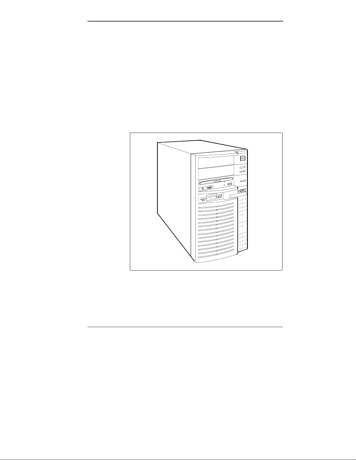
The NEC Image P90E and Image P100E series of minitower systems consist of powerful computers featuring
Intel’s 90 megahertz (MHz) and 100 MHz Pentium™
microprocessors, exceptional balanced system performance,
expandability, and upgradeability.
NEC Image P90E/P100E system
Features of Your System 1-1
Page 14

Each system is designed with a powerful architecture that
optimizes performance, connectivity, graphics display, and
expansion capabilities.
All systems feature a Peripheral Component Interconnect
(PCI) bus, Extended Industry Standard Architecture (EISA)
bus, enhanced Integrated Device Electronics (IDE) technology, fast small computer system interface-2 (SCSI-2)
technology, and PCI/EISA bridge technology.
A key feature of the Image P90E and Image P100E systems
is the PCI/EISA Bridge Component. The Bridge provides a
link between the system’s SCSI or IDE devices and the PCI
bus, and between any optional SCSI, PCI, EISA, ISA, or
IDE devices that you may install.
SYSTEM CONFIGURATIONS
The Image P90E and Image P100E systems come in several
configurations.
■ Image P90E
single-processor diskless systems (no hard disk or
single-processor systems with an IDE hard drive
■ Image P100E
single-processor systems with an IDE hard drive
single-processor systems with a SCSI-2 hard drive
1-2 Features of Your System
CD-ROM reader)
and an IDE quad-speed CD-ROM reader
and an IDE quad-speed CD-ROM reader
and an IDE quad-speed CD-ROM reader
Page 15

All hard disk systems are shipped with the MS-DOS and
Windows for Workgroups operating systems installed on
the hard disk. The diskless systems ship with diskettes containing the operating systems.
The label on the carton that the system is shipped in
identifies your configuration. Your system’s configuration
is also displayed during system startup ( see Chapter 2,
“Using Your System,” for startup information.)
KEY FEATURES
NEC designed your Image system with technologies that
help you get the most out of your computer. Key features
include:
■ Intel 90-MHz Pentium microprocessor (Image P90E)
■ 16 kilobyte (KB) internal dual write-back cache,
or Intel 100-MHz Pentium microprocessor (Image
P100E) for powerful processing
integrated on the microprocessor
■ 256-KB standard write-back secondary cache memory
■ 16-megabyte (MB) standard RAM memory, upgrade-
able to 256 MB
■ Optional upgrade for adding a second processor to
provide dual-processor capabilities
■ 32-bit EISA/PCI local bus for fast data transfer
■ EISA/PCI Bridge Component that links the EISA bus to
the PCI bus
■ System BIOS containing the ROM-based System Setup
utility
■ EISA Configuration utility (ECU) for setting EISA,
PCI, or ISA expansion device parameters
Features of Your System 1-3
Page 16

■ EZ-SCSI Setup utility for setting SCSI parameters
■ System input/output (I/O) controller integrating serial
ports, parallel port, SCSI-2 port, enhanced IDE hard
disk controller, SCSI-2 controller, and diskette drive
controller
■ Extended super video graphics accelerator (VGA) con-
troller with 2-MB interleaved video dynamic random
access memory (DRAM) standard
■ Flash ROM for fast economical BIOS upgrades
■ Quad-speed IDE CD-ROM reader (hard disk configura-
tions only)
■ Plug and Play operating system (O/S) support for Plug
and Play ISA expansion boards
■ Display Data Channel (DDC) support for automatic
configuration of resolutions and refresh rates for DDCcompliant monitors
■ System security for ensuring system use by authorized
users only.
See the following sections for descriptions of the key
features of the Image P90E and Image P100E systems.
(Refer to Appendix B for system specifications.)
Processor Subsystem
The Image P90E system uses a 64-bit, 90 MHz Pentium
microprocessor. The P100E system uses a 64-bit, 100 MHz
Pentium microprocessor.
The 90-MHz and 100-MHz processors each have 16 KB of
primary write-back internal cache, 8 KB for instructions
and 8 KB for data. Integrated into the processor is a math
coprocessor.
1-4 Features of Your System
Page 17

To use the Pentium processor’s power, each system
features an optimized high-speed 64-bit data bus and a
complementary 256-KB burst-mode write-back secondary
cache.
The synchronous cache design uses 9-nanosecond (ns) static
random access memory (SRAM) that allows data to be sent
or received from cache at the fastest possible burst rate
supported by the Pentium processor.
The Pentium processor is compatible with 8-, 16-, and 32bit software written for the Intel386, Intel486, and
Pentium microprocessors.
A 320-pin zero insertion force (ZIF) socket comes
integrated on the system board. The socket supports an
optional second processor for dual-processor capability.
System Memory
Each system comes standard with 16-MB of memory and
supports base and extended memory.
System memory can be expanded up to 256 MB, using
optional single in-line memory modules (SIMMs) installed
in SIMM sockets.
PCI Local Bus
The industry-standard PCI local bus is a highly-integrated
32-bit I/O interface that offers the highest performance
local bus available for the Pentium processor. The PCI bus
supports burst modes that send large chunks of data across
the bus, allowing fast displays of high-resolution images.
The high bandwidth PCI local bus eliminates the data
bottleneck found in traditional systems, maintains maximum
performance at high clock speeds, and provides a clear upgrade path to future technologies.
Features of Your System 1-5
Page 18

EISA Bus
The system’s integrated bit-block transfers (BitBLT)
graphics accelerator, IDE controller, and Fast SCSI-2 host
adapter use the 32-bit PCI local bus, which increases system performance and frees the Pentium processor for other
system activities.
The PCI bus is linked to the EISA bus through the
PCI/EISA Bridge Component link and the EISA System
Component link. The links allow concurrent operation.
The system incorporates a high-performance 32-bit EISA
bus with full bus-mastering capability. Advantages of EISA
are:
■ EISA’s 33-MB per second burst mode data transfer rate
increases the speed of I/O operations which is very
important for configurations with multiple storage
devices.
■ EISA’s bus-mastering capability allows maximum sys-
tem throughput by distributing the workload to intelligent subsystems. This creates balanced system
performance where no one subsystem impedes the
activity of another.
■ EISA boards are software configurable, unlike ISA
boards which require jumper settings, switch settings,
and configuration files.
■ EISA fully supports downward compatibility with
installed ISA hardware.
The EISA bus is linked to the PCI bus through the
PCI/EISA Bridge Component link and EISA System Component link. The links allow concurrent operation.
1-6 Features of Your System
Page 19

Integrated Fast SCSI-2
Integrated Fast SCSI-2 provides connection of up to five
internal SCSI-2 devices, up to seven external SCSI-2 devices, or a combination of internal and external devices (not
to exceed seven devices total). Devices supported include
hard disk drives, tape back-up drives, and CD-ROM readers.
The system uses a PCI local bus Fast SCSI-2 host adapter
integrated on the system board. The Fast SCSI-2 features:
■ a synchronous data transfer rate of 10 MB per second:
twice as fast as the regular SCSI
■ asynchronous data transfer rates up to 5 MB per second
■ support for the common command set (CCS) for com-
patibility
■ a command queuing feature that enhances multi-tasking
performance and helps reduce bottlenecks in I/O operations.
IDE Interface Controller
The IDE controller provides an enhanced IDE interface to
the PCI bus. The controller supports up to 11 MB per second 32-bit wide data transfers on the high-performance PCI
local bus.
The controller supports IDE devices connected to the
primary and secondary PCI/IDE connectors on the system
board. The two PCI/IDE connectors provide support for up
to four enhanced IDE devices.
The controller also has an automatic sensing feature for
detecting EISA hard disk controllers.
Features of Your System 1-7
Page 20

System I/O Controller
The system I/O controller integrates, on one chip, the
controller functions for the system’s two serial ports,
enhanced bi-directional parallel port, and diskette drive.
The controller supports up to two drives (diskette or tape).
The controller is disabled through the system’s BIOS if an
alternate diskette drive controller is installed.
Video Features
An integrated 32-bit BitBLT graphics accelerator on the 32bit PCI local bus provides high-performance graphics
capabilities. The PCI local bus graphics subsystem
features:
■ 2 MB of video DRAM
■ 24-bit High Color and True Color graphics.
The graphics accelerator speeds the movement of large
blocks of image data in video memory. As display resolutions increase, image creation and movement into video
memory are critical factors in graphics performance.
The graphics accelerator is specifically designed for graphics-intensive bit-block transfers, pattern-fill operations, text
and color pixel amplification, and scrolling. The accelerator
minimizes bus traffic by offloading the tasks normally performed by the processor.
The High Color graphics feature provides up to 1024 by
768-pixel high-resolution color with up to 64K colors. The
True Color graphics feature provides up to 800 by 600pixel high-resolution color with up to 16.8 million colors.
In addition to the standard VGA connector, a VESAcompliant feature connector is provided.
1-8 Features of Your System
Page 21

Flash ROM
NEC's Flash ROM allows fast, economical BIOS upgrades.
NEC Flash ROMs are re-programmable system and video
EPROMs.
With NEC’s Flash ROM, a ROM BIOS change:
■ is fast and easily done using a BIOS Update utility
obtainable from NEC
■ eliminates the expensive replacement of ROM BIOS
chips, and reduces system maintenance costs
■ reduces inadvertent system board damage that can take
place when replacing ROMs
■ facilitates adopting new technology while maintaining
corporate standards
■ gives network administrators company-wide control of
BIOS revisions.
IDE Quad-Speed CD-ROM Reader
The IDE quad-speed CD-ROM reader comes standard with
all hard disk systems. The reader features quad-speed technology, allowing it to operate at different speeds depending
on whether the CD-ROM disc you are using contains data
or music.
Quad-speed technology allows the CD-ROM reader to
transfer computer data up to 700 KB per second, four times
faster than ordinary CD-ROM readers. This allows you to
get your data faster.
Features of Your System 1-9
Page 22

Asset Management and System Security
The Image P90E and Image P100E systems come with the
following asset management and system security features:
■ Asset Management Information — displays the system
board serial number created during manufacturing at
NEC.
■ System Security — password protection ensures that
only authorized persons are allowed access to system
files.
PRODUCT INFORMATION
NEC offers several ways for you to obtain product information and support. If you have access to a fax machine,
you can use NEC’s FastFacts™ for product information.
If you have access to a modem, you can use NEC’s Bulletin
Board Service (BBS), the Internet, or America Online
obtain NEC product support.
NEC’s FastFacts service is described in the following
section. For information on using the BBS, Internet, or
America Online, refer to Chapter 9 in this guide.
®
to
NEC FastFacts
NEC’s FastFacts is a self-help, automated electronic information service that you can use to obtain up-to-date product
application notes, installation procedures, troubleshooting
tips, data sheets, technical information bulletins, illustrated
parts lists, and other information about your system.
Using a fax machine, you can obtain information from the
FastFacts service 24 hours a day, 7 days a week. You simply call the FastFacts number on your touch-tone telephone,
order the information you want by following the voice
prompts, and FastFacts will automatically fax you the information.
1-10 Features of Your System
Page 23

If you are new to FastFacts, you should first order a catalog
that lists the available documents and the document numbers. Current catalogs include:
■ Catalog 1, Monitors, Graphics Boards, and Data Projec-
tor Products
■ Catalog 2, CD-ROM Hardware and Software, Printers,
and Disk Drive Products
■ Catalog 3, Laptop, Desktop, and Server Computer
Products
■ Catalog 4, NEC Products for the Macintosh
■ Product and Configuration Index.
A catalog of all current technical information bulletins can
be ordered by requesting document number 72842228.
A catalog of current illustrated parts breakdowns can by
ordered by requesting document number 42228.
A set of instructions for using FastFacts can be ordered by
requesting document number 63233469.
Due to the dynamic nature of FastFacts, documents are
added and removed constantly, therefore all catalog and
document subjects and order numbers are subject to change
at any time and without notice.
Order information from FastFacts as follows.
1. Be sure your fax machine is on. Have handy the docu-
ment number for the document you want.
2. At your touch-tone telephone, call 1-800-366-0476
(U.S. and Canada only).
For international use, enter the international long dis-
tance access number, the U.S. country code, and the
U.S. telephone number (1-708-238-7800).
Features of Your System 1-11
Page 24

3. Listen to the instructions provided by the voice prompts.
Press
1 if you do not want an introduction to FastFacts.
Follow the automated instructions to order your document or catalog.
Press
2 if you want an introduction to FastFacts. Follow
the automated instructions to order your document or
catalog.
4. When asked by the voice prompts, enter your fax num-
ber and telephone number.
For international use, first enter the international long
distance access number (011), your country code, your
area code or city code, then your fax number.
The information requested will be automatically sent to
your fax machine. Please wait for the ordered document to
arrive at your fax machine before calling to order more
documents. If FastFacts attempts to send the second order
before the first order is completed, the order may be
canceled. After three tries, FastFacts assumes that your line
is busy and terminates any further processing of the order.
1-12 Features of Your System
Page 25

2
Using Your System
If you haven’t already set up your system, do so now, using
the steps on the NEC Image P90E/P100E Quick Setup
sheet that comes with your system (hard disk systems only).
NOTE: NEC recommends that after your system is
set-up, you read Appendix A , “Setting Up a Healthy
Work Environment.” The appendix contains
guidelines that help you use your system
productively and safely.
Once you have done the above, familiarize yourself with
the system’s hardware features, including the system unit,
CD-ROM reader, mouse, and keyboard. These features are
described next, under “System Hardware Features.”
See “System Operation” in this chapter for procedures
that you will use regularly to operate your computer.
Information includes system start-up, diskette loading, CD
loading, reset, backup procedures, and system shutdown.
NOTE: Once familiar with system operation, you
should run the ROM-based System Setup utility to
check your computer's current time and date (see
Chapter 3). Be sure that the system's clock is set for
your time zone.
Using Your System 2-1
Page 26
SYSTEM HARDWARE FEATURES
The following sections introduce basic hardware features of
the system unit, CD-ROM reader, keyboard, and mouse.
Front Panel Controls
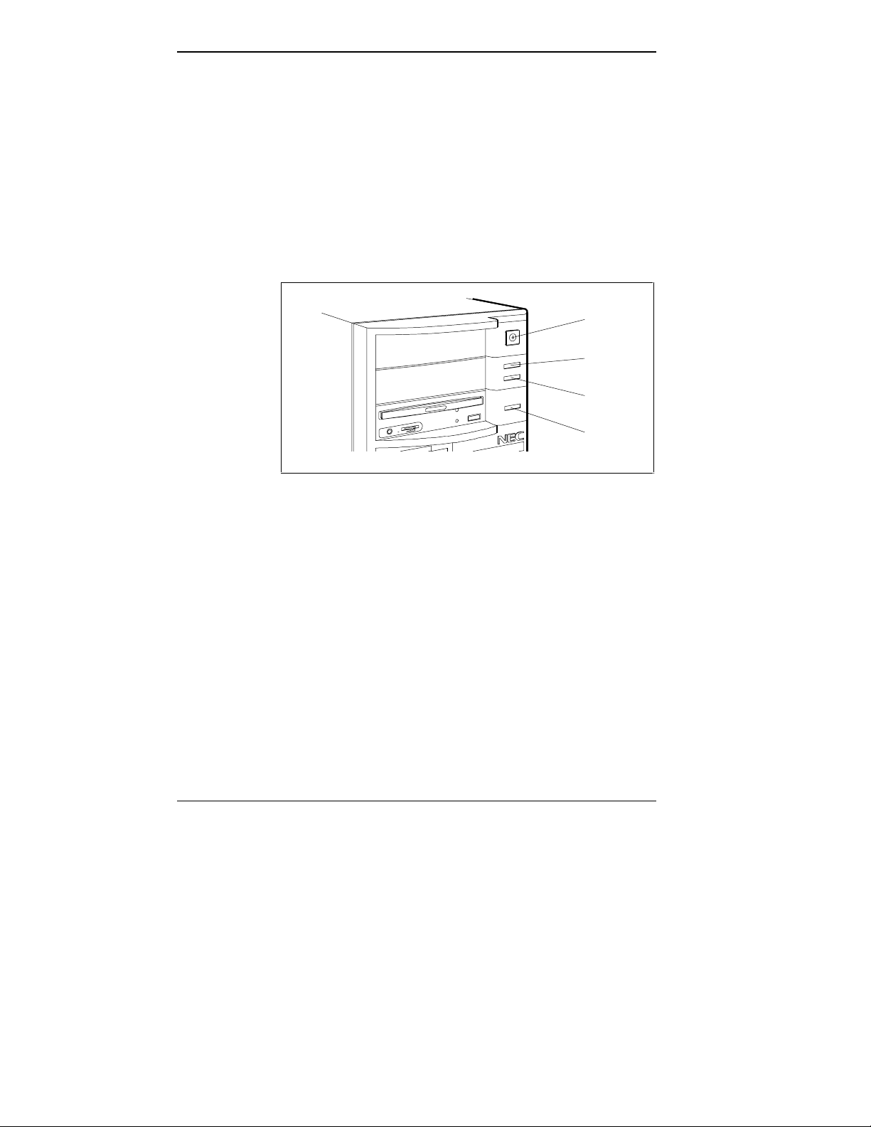
Controls, lamps, and other frequently used features are
located on the front panel of the system unit. The following
figure shows front panel features on the system unit. Brief
descriptions of these features follow the figure.
Power
Button
Power
Lamp
Disk
Lamp
Reset
Button
Front panel controls and lamps
Power Button
The power button controls power to the system unit.
Pressing the button turns power on and off. The power
button is almost flush with the front panel when power is
off and indented when power is on.
Lamps
The front panel contains a power lamp and a disk lamp. A
lit power lamp (green) indicates that the system unit is
powered on. A lit disk lamp (green) indicates when a hard
disk is performing a read or write operation.
2-2 Using Your System
Page 27
CAUTION: Do not turn off the system while the
disk lamp is lit or you may damage your hard disk or
data.
Reset Button
The reset button lets you restart your system after it has
been powered on.
CAUTION: Position your system to prevent hitting
the reset button by accident, thus avoiding
accidental resets which can damage your hard disk
or data.
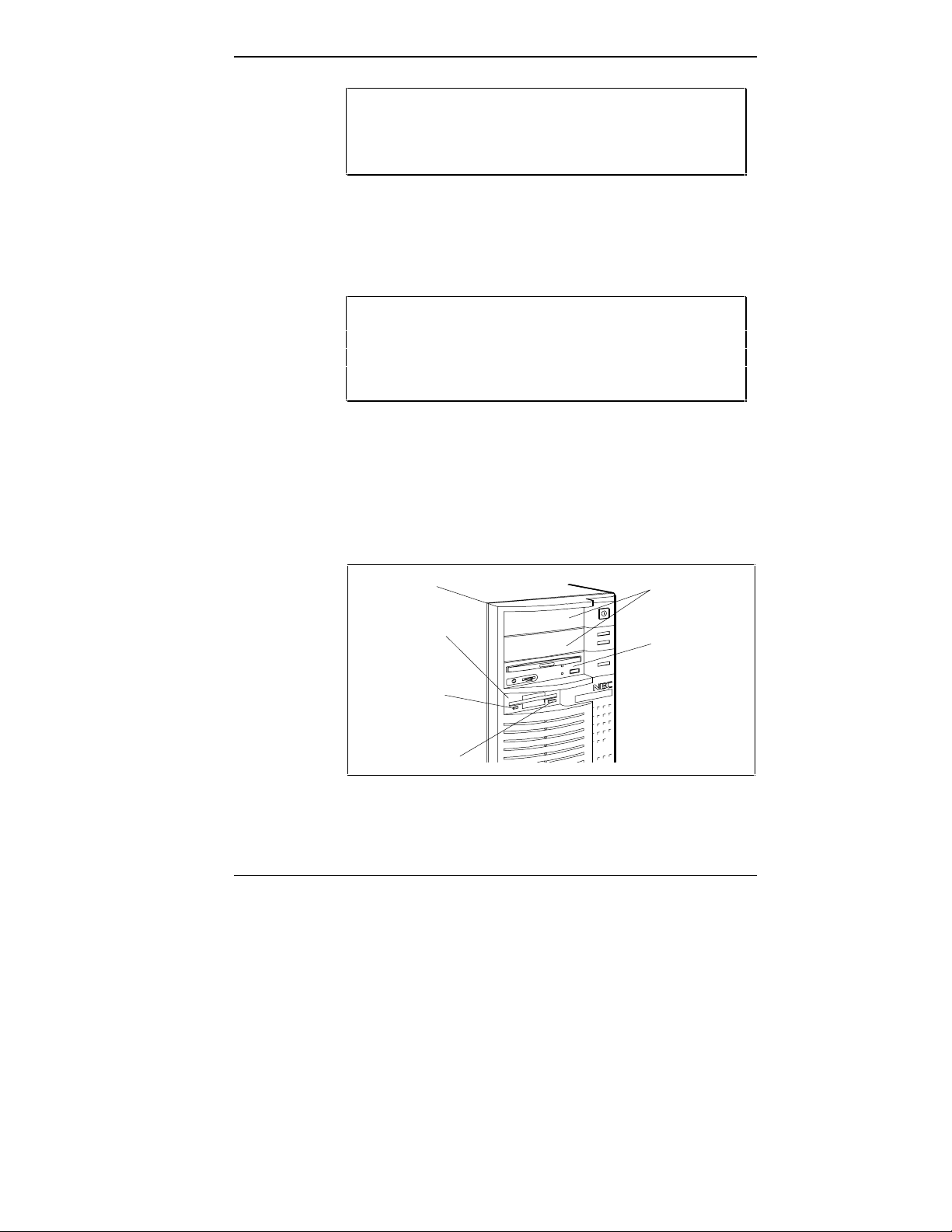
Front Panel Storage Devices
The diskette drive (standard on all systems) and CD-ROM
reader (hard disk systems only) are on the front panel of the
system unit, as shown in the following figure. Brief
descriptions of the devices follow the figure.
Diskette
Drive A
Diskette Drive
Busy Lamp
Diskette
Release
Button
Accessible
5 1/4-Inch
Device Slots
CD-ROM
Reader
Front panel storage devices
Using Your System 2-3
Page 28

Diskette Drive
Your system comes with a 3 1/2-inch 1.44-MB diskette
drive (standard on all systems). The drive is assigned as
drive A. Use this drive if you need to load and start
programs from a diskette.
Diskette drive controls include a release button and a drive
busy lamp. The diskette release button releases an inserted
diskette from the drive. The diskette drive busy lamp lights
when the drive is reading from or writing to a diskette.
CAUTION: To prevent damage to your diskette
drive and data, do not turn off the system or remove
the diskette while the diskette drive busy lamp is lit.
IDE Quad-Speed CD-ROM Reader
All hard disk systems come with an IDE quad-speed CDROM reader. The reader is assigned as drive E.
Use your CD-ROM reader to load and start programs from
a compact disc (CD). You can also use the reader to play
your audio CDs. The reader is fully compatible with Kodak
Multisession Photo CDs and standard audio CDs.
The CD-ROM reader operates at different speeds depending
on whether the CD you are using contains data or music.
This allows you to get your data faster.
2-4 Using Your System
Page 29
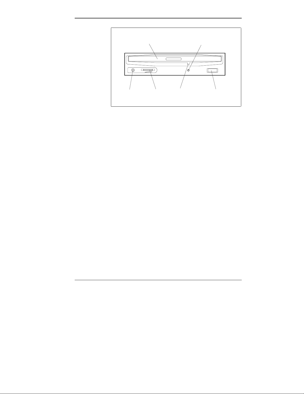
CD Disc Tray
Headphone
Jack
Volume
Control
Emergency
Eject Screw
Activity
Indicator
Eject
Button
Quad-Speed IDE CD-ROM reader
The quad-speed IDE CD-ROM reader has the following
features:
■ Headphone jack — for connecting optional headphones
with a stereo mini-jack plug.
■ Volume control — for adjusting the headphone volume
when using optional headphones.
■ Activity indicator — for monitoring operation of the
reader.
■ CD disc tray — for loading a CD disc.
■ Emergency eject — allows manual opening of the CD
tray if the eject function is disabled by software or if a
power failure occurs.
■ Eject button — opens and closes the CD tray.
Using Your System 2-5
Page 30

Accessible Device Slots
Hard disk systems ship with two empty device bays (three
for diskless systems), ready for installation of optional
storage devices with a 5 1/4-inch form factor. Use these
bays for installing optional devices such as a diskette drive,
tape drive, or CD-ROM reader.
Internal Storage Device
An internally mounted 3 1/2-inch hard disk (IDE or Fast
SCSI-2, depending on your system configuration) comes
standard in hard disk configurations. The hard disk is
designated as drive C. NEC formatted your hard disk and
installed your software on the hard disk at the factory.
CAUTION: Do not format the hard disk. Formatting
the hard disk destroys all of the data on the disk.
Rear Panel
The rear panel provides connectors for setting up the
system, as shown in the following figure. Each connector is
briefly described in the following paragraphs.
Mouse Port
The mouse port supports a personal system (PS)/2compatible mouse. Your mouse attaches to this port.
CAUTION: Always turn off system power before
connecting or disconnecting the mouse. Failure to
do so can damage the mouse or the system.
2-6 Using Your System
Page 31
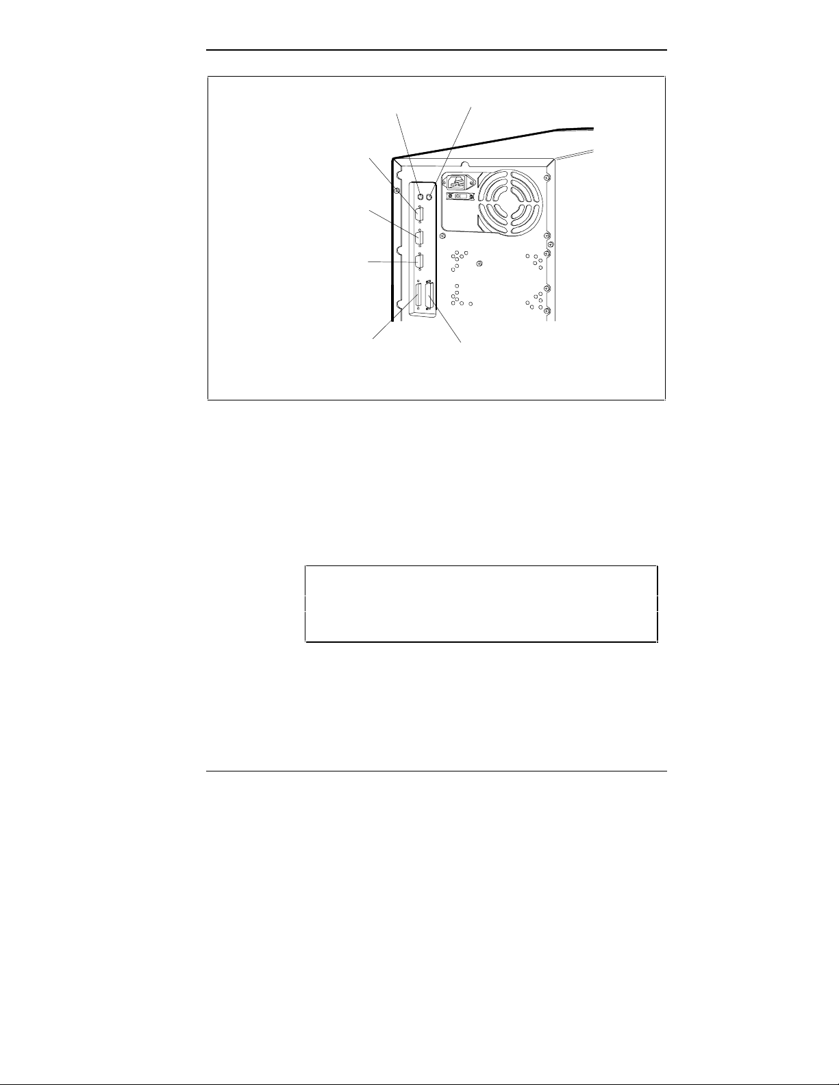
Serial Port 1
Serial Port 2
VGA Monitor
Connector
Keyboard Port
Mouse Port
External
SCSI-2
Connector
Keyboard Port
Parallel
Printer Port
Rear panel connectors
The keyboard port supports a PS/2-compatible, 101-key
keyboard (U.S. and Canada only) or a 102-key keyboard
(United Kingdom and Germany only) with a 6-pin mini DIN
connector. Your keyboard attaches to this port.
CAUTION: Always turn off system power before
connecting or disconnecting the keyboard. Failure to
do so can damage the keyboard or the system.
Using Your System 2-7
Page 32

Serial Ports
The dual serial ports feature baud rates up to 19.2 KB/sec
with a word length of 5 to 8 bits. You can connect up to two
RS-232C serial devices with 9-pin connectors, such as a
pointing device or a serial printer, to the system.
VGA Monitor Connector
The monitor connector supports a video graphics array
(VGA)-compatible monitor with a 15-pin connector.
Support includes NEC Plug and Play monitors.
SCSI-2 Port
The SCSI-2 port allows the connection of an external SCSI
cable and up to seven external SCSI-2 devices such as a
CD-ROM, hard disk, or tape drive.
Printer Port
The printer port is the system's parallel interface connector.
This enhanced bidirectional parallel port supports Enhanced
Parallel Port (EPP) and Extended Capabilities Port (ECP)
standards for increased data transfer rates to your printer.
Use this port to connect a parallel printer with a 25-pin
connector to the system.
Expansion Slot Covers
The expansion slot covers are removable, allowing the
installation of up to five expansion boards to the system.
One slot is for a 32-bit PCI-compatible board. A second
shared slot is for either an EISA board (8-bit, 16-bit or 32bit) or a PCI board. The three remaining slots are for EISA
or ISA boards.
2-8 Using Your System
Page 33
Cooling Fans
Two cooling fans in your system provide proper ventilation
to cool system components and prevent overheating. One
fan is an integral part of the power supply. The second fan
is mounted on the processor. For proper ventilation, keep
the areas around the system clear of obstructions.
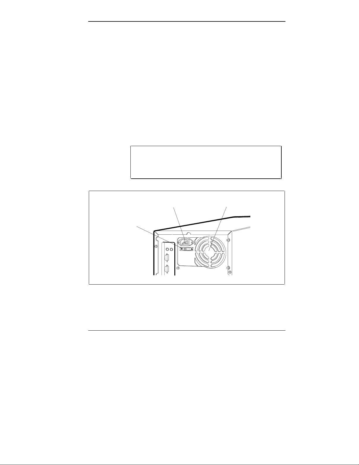
Voltage Selector Switch
The voltage selector switch is on the rear of the system, as
shown in the following figure. The switch sets the voltage
for your system to 115 volts (V) or 230 V. Most outlets in
the United States, Canada, and Taiwan are 115 V. Most
outlets in Europe, Australia, and Asia are 230 V.
CAUTION: Be sure that the voltage selector switch
is set correctly for the voltage in your area (115 V or
230 V.
System Power
Socket
Voltage Selector
Switch
Fan
Rear panel power supply features
Using Your System 2-9
Page 34

System Power Socket
The system power socket is on the rear of the system, as
shown in the preceding figure. Use this socket for
connecting the system unit power cord to the system unit
and to your wall outlet.
Keyboard
An industry-standard, membrane keyboard comes with your
system (see the following figure). The keyboard is
detachable and has adjustable supports. A general
description of the keyboard follows.
Keyboard key functions depend on the operating system or
software application program you use. Check the
documentation that comes with your operating system or
software for function information.
NOTE: Most of the keys have a repeat function.
When you hold down a key, the character or
function repeats until you release the key. You can
set keyboard auto-repeat and delay rates in the
Setup utility (see Chapter 3).
The keyboard’s status lamps indicate the status of the Num
(Numeric) Lock, Caps (Capital) Lock, and Scroll Lock
keys.
2-10 Using Your System
Page 35
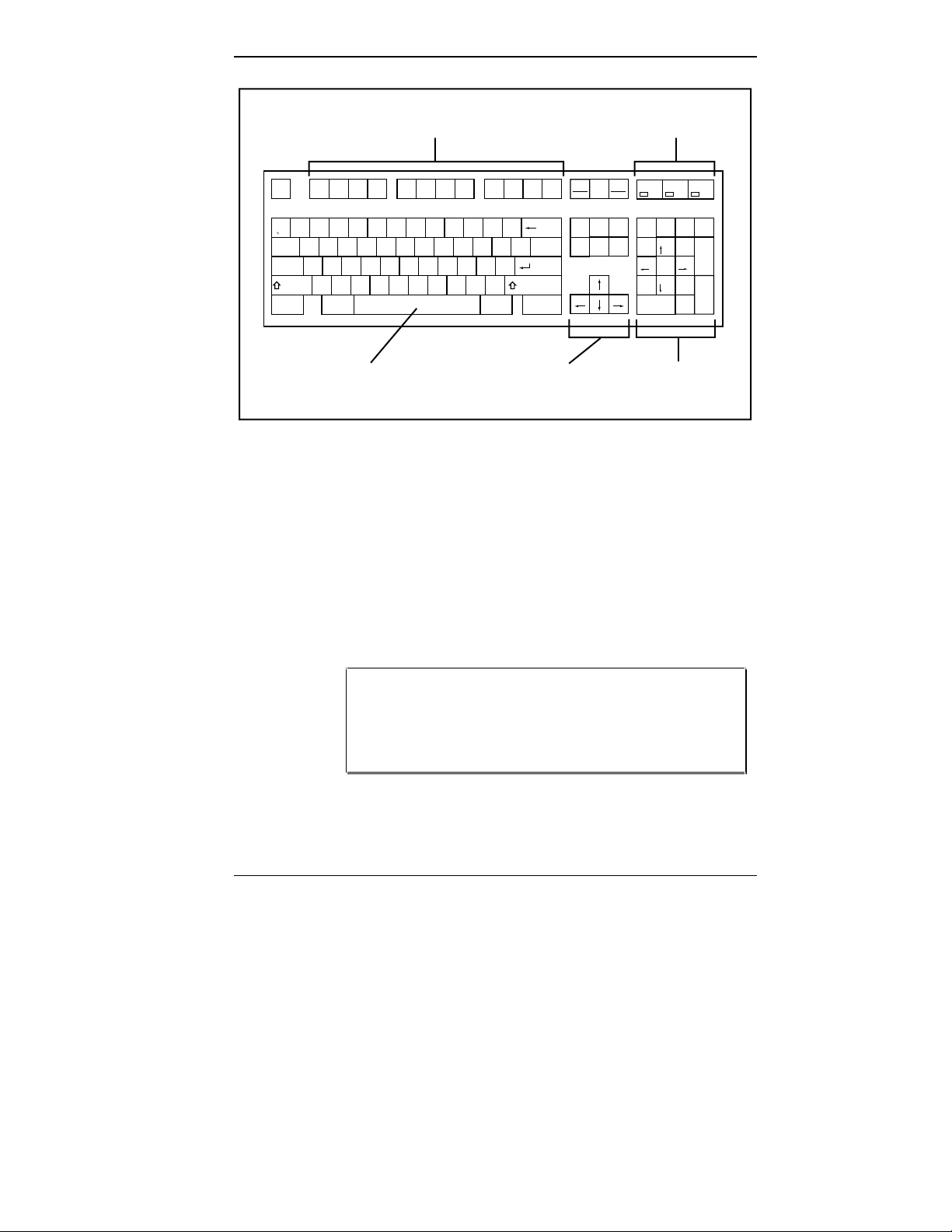
Function Keys Status Lamps
Print
Pause
Num
Caps
Esc
F1 F2 F3 F4 F5 F6 F7 F8 F9 F10 F11 F12
!
@
~
1
2
3#4$5%6^7&8*9(0)-_=
Q W E R T Y U I O P {
Tab
|
A
Caps Lock
Ctrl
S D F G H J K L :
Z X C V B N M < > ?
Shift
Alt Alt
;
/
.,
+
Backspace Insert
||
}
[]\
"
Enter
'
Shift
Ctrl
Screen
Sys Rq
Delete
Scroll
Lock
Home
End
Lock
Break
Num
Page
Lock
Up
7
Page
Down
Home
46
1
End
0
Ins
Lock
/
*
8
9
Pg Up
5
23
Pg Dn
*
Del
Scroll
Lock
-
+
Enter
Typewriter Keys
Standard Cursor
Control Keys
Numeric Keypad/
Cursor Control Keys
Keyboard features (U.S. model)
The numeric keypad/cursor control keys work like a
numeric keypad. In Numeric Keypad mode, the Num Lock
lamp is on. To use the keys to control the direction of the
cursor, press the Num Lock key (Num Lock lamp goes off).
To return to the Numeric Keypad mode, press the Num
Lock key. To use a keypad cursor key while in Numeric
Keypad mode, press the Shift key and the keypad cursor
key.
NOTE: The system enables Numeric Keypad mode
at power-on. You can set the Numeric Keypad mode
off at power-on with the Setup utility (see
Chapter 3).
Using Your System 2-11
Page 36

Mouse
The standard cursor control keys control the direction of the
cursor. The Num Lock state (Num Lock lamp is lit) does
not affect the operation of these keys.
The typewriter keys function as standard typewriter keys.
A PS/2-compatible mouse comes standard with your
system. The mouse is fast, accurate, and simple to use.
Your mouse lets you take full advantage of applications
with a Graphical User Interface (GUI).
CAUTION: To prevent damage to your mouse and
to the system, turn off the system power before you
connect or disconnect your mouse.
Also, the system fails to recognize that a mouse is attached
if you connect the mouse after system power is on.
SYSTEM OPERATION
The following sections describe procedures you use when
you operate your computer. These procedures include:
■ powering on
■ diskette loading
■ CD loading
■ system reset
■ backup
■ powering off.
2-12 Using Your System
Page 37

Powering On
Powering on your computer (called cold boot) initiates an
automatic routine that prepares your computer for use. A
cold boot performs diagnostic tests, sets system parameters
last saved by the Setup utility, reinitializes all devices, and
loads the operating system.
Power on (boot) your computer as follows.
1. Check that the power cables from the monitor and
system unit are connected to a surge protector (optional)
and a wall outlet.
CAUTION: Be sure that the voltage selector switch
is set correctly for the voltage in your area (115 V or
230 V).
2. If you are booting from the hard disk make sure that the
diskette drive is empty.
If you are booting from the diskette drive, be sure that
you have a diskette in drive A containing operating
system files.
NOTE: The system looks for the drive containing
operating system files. If you have a diskette with
MS-DOS or another operating system's files in drive
A, the system boots from the diskette drive. If you
do not have a diskette in drive A, the system boots
from the hard disk.
A diskette without operating system files in drive A
prevents a system boot and displays the error
message, “non system disk installed in drive A.”
Using Your System 2-13
Page 38

3. Turn on power to the monitor.
4. Turn on power to the computer by pressing the power
button.
The computer’s power lamp lights and the start-up
screen appears on the monitor. If necessary, adjust the
contrast and brightness controls on the monitor.
The start up screen displays system information including
BIOS version, BIOS extensions, SCSI ID settings, system
configuration information, system board serial number, host
adapter settings, and other related information.
NOTE: You can pause the start-up screen at any
time by pressing the Pause key. Restart by pressing
the F1 key.
The start-up screen also briefly displays an “F2 to run
SETUP” message at the bottom left of the initial screen and
a “Press Ctrl A for SCSI Select Utility” message at the last
screen. The appropriate utility can be accessed by pressing
F2 (for setup) or Ctrl A (for SCSI) immediately on message
display.
NOTE: Access the Setup utility by pressing F2
twice when the “F2 to run SETUP” message
appears. Press F2 as soon as the message is
displayed, as it appears only briefly.
Access the SCSI utility by pressing Ctrl A as soon
as the “Press Ctrl A for SCSI Select Utility”
message appears.
2-14 Using Your System
Page 39

During the boot-up process, the system performs Power-On
Self-Test (POST) diagnostic tests that check major
hardware components, such as memory and interface
circuits. It compares the hardware it finds with parameters
last saved by the Setup utility.
Several configuration messages appear on the screen during
POST. If POST finds any discrepancies between the
parameters it finds and the parameters last saved, it displays
an error message. The system then prompts you to run the
Setup utility to correct the configuration.
If POST does not find any discrepancies in its configuration
test, the computer loads system files into memory.
Once the system files are loaded, the system automatically
loads Microsoft Windows for Workgroups.
Your system is ready for use.
Diskette Loading
Use the following procedure to insert and remove a 3 1/2inch diskette in the standard diskette drive.
1. Hold the diskette label side up and insert it into the
diskette drive until you hear a click.
2. To remove a diskette from the diskette drive, press the
release button on the drive.
CAUTION: Do not turn off system power or remove
a diskette from the diskette drive when the diskette
drive lamp is lit. To do so can damage both the data
on the diskette and the drive.
Do not reset the system (except as a last resort)
when the diskette drive is in use.
Using Your System 2-15
Page 40
CD Disc Loading
Use the following procedure to load a CD into the quadspeed CD-ROM reader.
NOTE: System power must be on before you can
load a disc into the CD-ROM reader.
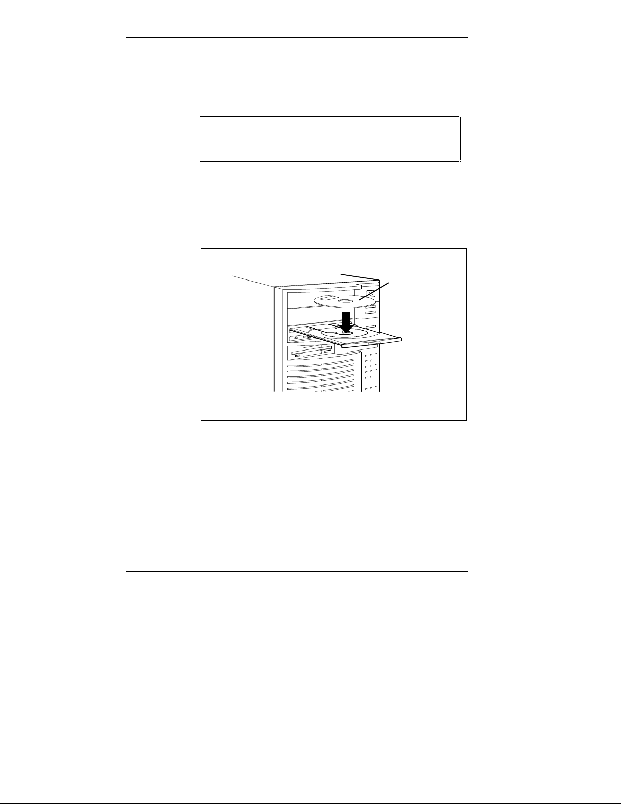
1. Press the Eject button to open the disc tray.
2. With the printed side facing up, hold the CD by its edges
and place it in the tray (see the following figure).
Print Side
3. Press the Eject button to close the tray.
The activity lamp flashes on and off when the reader
The lamp is constantly on when you are playing an
2-16 Using Your System
Loading a CD disc into the tray
is doing data access or data transfer.
audio disc. At all other times, the lamp is off.
Page 41

System Reset
4. Remove the disc by pressing the Eject button to open the
tray. Remove the disc, and press the Eject button to
close the tray.
If the eject function is disabled by software or a power
failure, use the emergency eject function (see Chapter 9).
A system reset is a system restart after your computer is
powered on. You can reset your computer manually when a
software or hardware problem prevents you from using the
system. You can initiate a reset automatically under certain
conditions.
The following sections describe conditions for manual and
automatic resets.
CAUTION: Resetting the system removes
information from RAM disks, volatile system
memory, and application programs. Information
saved in files on disk, like program and data files,
are not usually affected by a system reset.
Manual Reset
Reset your computer manually if a software or hardware
problem prevents you from using the system. Situations that
require a reset include the following:
■ The system does not respond to keyboard input (requires
a cold boot).
Using Your System 2-17
Page 42

■ You cannot exit from an application program. In this
case, first try a software reset in Windows for
Workgroups (see the following instructions for a
software reset).
■ You change the system configuration after editing the
CONFIG.SYS file.
■ You change your system configuration settings or
operating system and you want to start the system with
the new settings.
■ The monitor screen is black. If your screen is black, it
may only need a simple adjustment. Before you reset the
system, check the following:
Adjust the contrast and brightness controls on the
monitor.
Check that your monitor is properly connected and
the monitor power is on.
You can reset the system in two ways:
CAUTION: Unless absolutely necessary, do not
reset the system when the hard disk lamp or
diskette drive busy lamp is on. Information on the
hard disk or diskette might be lost or damaged.
■ With a software reset.
Press and hold
are pressed, the system resets.
A software reset performs a warm boot. It clears volatile
system memory and reloads the operating system.
■ With a hardware reset.
Press the reset button on the front of the system unit.
2-18 Using Your System
Ctrl, Alt, and Del. When all three keys
Page 43

Automatic Reset
An automatic reset performs a cold boot. The system
automatically resets itself when you exit from the Setup
utility.
Backup
Backup procedures are important for the efficient and
effective use of your computer. Protect your program and
data files with regular backup procedures.
See your MS-DOS and Windows for Workgroups
documentation for information about backup procedures.
Make backup copies of your program and data files that are
on diskette and on the hard disk.
The standard practice for diskette backup is to copy each
diskette, store the original in a safe place, and use the copy
as your working diskette. You can use the MS-DOS
DISKCOPY command for making copies of your diskettes.
See your MS-DOS documentation for information about
using the command.
Or turn the system power off, wait at least five seconds,
and then turn the power on.
A hardware reset performs a cold boot. It checks the
hardware and reloads the operating system.
Powering Off
Use the following steps to shut down (power off) your
computer.
1. Save your work. See the documentation that comes with
your application program.
2. Exit the application program.
Using Your System 2-19
Page 44

If you are in Windows for Workgroups, exit the
Program Manager by double clicking on the upper left
block. Select “OK” at the prompt to exit Windows.
3. Make sure that the hard disk and diskette drive are not
in use. A lit hard disk lamp or diskette drive busy lamp
indicates that a drive is in use.
4. Power off the system by pressing the power button. Turn
off power to your monitor.
CAUTION: Unless absolutely necessary, never
power off the system when the hard disk lamp or
diskette drive busy lamp is lit. Information on the
hard disk or diskette might be lost or damaged.
2-20 Using Your System
Page 45

Setting System
3
Parameters
This chapter describes the ROM-based Setup utility that
allows you to view and enter system configuration information. The Setup utility is pre-installed on your system and
ready to run.
Your system ships with the correct system parameters for
your configuration. Unless you add optional hardware
devices, you do not need to run the Setup utility to operate
your system. However, you might wish to run Setup to set
the time, date, and security features.
NOTE: If you are adding, moving, or removing an
optional EISA, PCI, Plug and Play ISA, non-Plug
and Play ISA, or SCSI expansion device, use the
ECU and SCSI utilities. See Chapter 4, “Using the
ECU and SCSI Utilities,” for information.
Use the Setup utility to:
■ check or change the time and date.
■ check or change the diskette drive type.
■ check or change IDE hard disk parameters.
■ check or change system parameters when you add or
remove PCI devices.
■ check or change your video device.
Setting System Parameters 3-1
Page 46

■ enable or disable the system’s VGA feature connector.
■ check or change memory cache or shadow settings.
■ check or change the system’s boot sequence.
■ check or change keyboard settings.
■ enable or disable the Plug and Play O/S feature.
■ check the installation of optional memory by comparing
the amount memory installed with the amount of memory displayed by Setup.
■ customize your system with security features such as
supervisor and user login IDs and passwords.
■ correct a hardware discrepancy when the Power-On-
Self-Test (POST) displays an error message and
prompts you to run Setup.
■ reset system parameters in the event that you need to
replace the RTC/battery module.
System configuration information is stored in nonvolatile
memory. Nonvolatile memory is a complementary metaloxide semiconductor (CMOS) chip backed up by a battery.
The battery is part of the real-time clock (RTC)/battery
module on the system board. The battery supplies continuous power to the CMOS memory and maintains configuration information when system power is off.
NOTE: NEC recommends that you print out or write
down your current Setup parameters and store the
information in a safe place. This lets you restore
your system to the current parameters if the
RTC/battery module ever needs replacement.
3-2 Setting System Parameters
Page 47
HOW TO START SETUP
To start the Setup utility, follow these steps:
1. Turn on or reboot your system. Setup briefly displays
the following message at the bottom left of the screen:
F2 to run SETUP
2. Press F2 twice as soon as the message is displayed, as it
appears only briefly. Setup’s Main menu appears similar
to the following screen.
NOTE: The screen shown is typical of your system.
The actual items on the Main menu depend upon
the hardware installed in your system.
PhoenixBIOS Setup — Copyright 1985-94 Phoenix Technologies Ltd.
Main Advanced Security Exit
System Time: [10 :19:20] Item Specific Help
System Date: [1/27/1995]
Diskette A: [1.44 MB, 3 ½"] <Tab>, <Shift-Tab>, or
Diskette B: [Not Installed] <Enter> selects field.
> IDE Adapter 0 Master: C: 540 Mb
> IDE Adapter 0 Slave: None
> IDE Adapter 1 Master: None
> IDE Adapter 1 Slave: None
Video System: [EGA/VGA]
> Memory Cache:
> Memory Shadow: [Enabled]
> Boot sequence: [A: then C:]
> Numlock: [Auto]
System Memory: 640 KB
Extended Memory: 7 MB
F1 Help ↑↓ Select Item -/+ Change Values F9 Setup Defaults
ESC Exit ←→ Select Menu Enter Select > Sub-Menu F10 Previous Values
Main menu
Setting System Parameters 3-3
Page 48

HOW TO USE SETUP
The Setup utility opens with the Main menu. The Main
menu displays the following:
■ Setup title line — displays the Setup utility name and
copyright message.
■ Menu bar — lists the four top-level menus (Main,
Advanced, Security, Exit) that you can choose to set
system parameters.
■ Menu summary — lists menu setup parameters for the
selected top level menu. You can set some parameters
directly from this window or you can set them using the
keys listed at the bottom of the screen.
■ Item Specific Help — provides help information for the
Setup option currently selected.
■ Legend bar — provides a summary of command keys
for using Setup.
■ General Help window — appears any time during Setup
when you press
two pages of general information about using Setup.
F1 or Alt H. The help window provides
The following sections describe how to use the Setup menu
to set system parameters.
The Menu Bar
The menu bar at the top of the Main menu lists these
menus:
■ Main — Use this menu for basic system configuration.
For example, select “Main” to set the system time,
system date, diskette drives, and video parameters. Use
this menu to check memory parameters.
3-4 Setting System Parameters
Page 49

■ Advanced — Use this menu to set integrated peripherals:
serial and parallel port addresses/interrupts, enable or
disable the diskette drive controller, select monitor type,
and enable or disable the VGA feature connector.
The menu provides menu items for setting advanced
chipset control, enabling or disabling Plug and Play, and
setting PCI device parameters.
The menu also lets you set parameters for large disks
(for example, to use large disks with Windows NT).
Some of the Advanced features may be accessible only
with a Supervisor password.
■ Security — Use this menu to edit and set Supervisor and
user IDs and passwords, set Backup and Virus-check
reminders, set network and diskette access, and enable
write-protection for the hard disk.
■ Exit — Exits the current menu.
To select an option from the menu bar, use the left and right
arrow keys.
See “Exiting Setup” in this chapter for a description on
exiting the Setup menu.
The Legend Bar
Use the keys listed in the legend bar on the bottom of the
Setup menu to make your selections or exit the current
menu.
The following table describes the legend keys and their
alternates.
Setting System Parameters 3-5
Page 50

Startup Functions
KEY FUNCTION
F1 or Alt-H Displays General Help window (described later
in this chapter).
Esc Exits the menu.
← or → arrow keys
↑ or ↓ arrow keys
Tab or Shift-Tab Moves cursor left and right.
Home or End Moves cursor to top or bottom of window.
Page Up or Page Down Moves cursor to top or bottom of window.
F5 or - Selects the Previous Value for the field.
F6 or + or Space Selects the Next Value for the field.
F9 Loads the Default Configuration values for
F10 Loads the Previous Configuration values for
Enter Executes Command or Selects submenu.
Alt-R Refreshes screen
Selects a different menu.
Moves cursor up and down.
this menu.
this menu.
Selecting a Menu Item
To select a menu item, use the arrow keys to move the cursor to the field you want. Then use the value keys (F5, -,
F6, +, or space bar) to cycle through the value for that
field. The Save Changes command in the Exit menu saves
the values currently displayed in all the menus.
3-6 Setting System Parameters
Page 51

Displaying a Submenu
A pointer (a right-pointing triangle) at the left of the
menu item indicates that the item contains selectable submenus. To display a submenu, use the arrow keys to move
the cursor to the menu item containing a submenu, then
Enter.
press
The Item Specific Help Window
The Item Specific Help window on the right side of each
menu displays the help text for the currently selected Setup
option. It updates as you move the cursor to each new field.
The General Help Window
Pressing F1 or Alt H on any menu brings up the General
Help window that describes the legend keys and their
alternates.
The scroll bar on the right of any window indicates that
there is more than one page of information in the window.
Use
Page Up and Page Down to display all the pages.
Pressing
Home and End displays the first and last page.
Press
THE MAIN MENU
The following table lists and describes the available
parameters when you select the Main menu in the legend
bar.
Parameters that can be modified directly from the Main
menu do not have a right-pointing triangle to the left of the
parameter name. These parameters can be modified by
pressing the F5, F6, - or + keys.
Esc to exit the current window.
Setting System Parameters 3-7
Page 52

Parameters with submenus that are available from the Main
menu have a right-pointing triangle to the left of the
parameter. Use the arrow keys to move the cursor to the
parameter, then press
Enter to open the submenu.
See the sections following the table for a description of
Main menu parameters and their submenus.
Main Menu Parameters
PARAMETER OPTIONS DESCRIPTION
System Time HH:MM:SS Sets the system time.
System Date MM/DD/YYYY Sets the system date.
Diskette A:
Diskette B:
IDE Adapter 0 Master* Autotype fixed disk
IDE Adapter 0 Slave* Autotype fixed disk
IDE Adapter 1 Master* Autotype fixed disk
IDE Adapter 1 Slave* Autotype fixed disk
Video System Monochrome
360KB, 5 1/4”
1.2MB, 5 1/4”
720KB, 3 1/2”
1.44MB, 3 1/2” (default)
2.88MB, 3 1/2”
Not Installed
Type
Multi-sector transfers
Type
Multi-sector transfers
Type
Multi-sector transfers
Type
Multi-sector transfers
EGA/VGA (default)
CGA 80x25
Selects the type of diskette
drive in your system.
Configures the IDE adapter.
Configures the IDE adapter.
Configures the IDE adapter.
Configures the IDE adapter.
Selects the default video
device.
3-8 Setting System Parameters
Page 53

Main Menu Parameters
PARAMETER OPTIONS DESCRIPTION
Memory Cache* External cache
Cache system BIOS area
Cache video BIOS area
Cache memory regions
Memory Shadow* System shadow
Video shadow
Shadow memory regions
Boot Sequence* A: then C:
C: then A:
C: only
Numlock* Auto
On
Off
System Memory Automatically detected
by the system
Extended Memory Automatically detected
by the system
* Parameter contains submenus.
IDE Adapters
IDE adapters control the IDE devices, such as IDE hard
disk drives and IDE CD-ROM readers. Your system has
two IDE controllers integrated on the system board.
Enables/disables external
cache.
Enables/disables video
shadow.
Selects system boot
sequence.
Selects power-on state of
Numlock and keyboard
Displays the amount of
conventional memory
detected at power-on.
Displays the amount of
extended memory detected
at power-on.
Setup supports up to four IDE devices, with an IDE adapter
for each of the following configurations:
1 Master
1 Master, 1 Slave
2 Masters
2 Masters, 1 Slave
2 Masters, 2 Slaves
Setting System Parameters 3-9
Page 54

The master/slave combination with an IDE hard disk is “1
Master.” If you add a hard disk to the fast PCI/IDE primary
port , the combination becomes “1 Master, 1 Slave.”
Jumper settings on the IDE device set the device to master
or slave (see the documentation that comes with the device).
Select the IDE Adapter option configuration directly from
the Main menu. Available options include:
■ IDE Adapter 0 Master
■ IDE Adapter 0 Slave
■ IDE Adapter 1 Master
■ IDE Adapter 1 Slave
IDE Adapter 0 configures the PCI/IDE primary port, IDE
Adapter 1 configures the PCI/IDE secondary port.
Each IDE Adapter parameter has a right-pointing arrow to
the left of it. Selecting the option displays IDE hard disk
parameters. Select an IDE Adapter option and set
parameters for each hard disk separately.
Use the following table to configure the IDE hard disk. If
your IDE hard disk features auto IDE type detection,
select the Autotype Fixed Disk parameter. The system
automatically detects the hard disk type and sets the
remaining parameters.
CAUTION: Incorrect settings can cause your sys-
tem to malfunction and not be able to read your
drive.
3-10 Setting System Parameters
Page 55

IDE Hard Disk Adapter Parameters
PARAMETER OPTIONS DESCRIPTION
Autotype Fixed
Disk
Type 1 to 39
Cylinders 1 to 2099 Specifies number of cylinders.
Heads 1 to 16 Specifies number of read/write heads.
Sectors/Track 1 to 63 Specifies number of sectors per track.
Write Precomp* 0 to 512
Multi-Sector
Transfers
LBA Mode Control Enabled (default)
32 Bit I/O Enabled (default)
Automatically
detected by the
system
User
None
Auto
None
2, 4, 8, 16
Sectors
Disabled
Disabled
Pressing
determine the hard disk type. If
successful, Setup fills in the remaining
fields on this menu and you do not need
to select the disk parameters.
Selecting 1 to 39 fills in all the remaining
fields with values for a predefined disk
type. The User setting prompts you to fill
in the remaining fields. The Auto setting
causes the system to determine disk
geometry at power on.
Specifies number of the cylinder at which
to change the write timing.
Specifies number of sectors in
multisector transfers.
Sets LBA mode Control on or off.
Sets 32 bit I/O to on or off.
Enter causes the system to
Transfer Mode Standard
Fast PIO1
Fast PIO2
Fast PIO3
Specifies the transfer mode for moving
data to and from the hard drive. Standard
is the slowest mode but the most
compatible. Fast PIO1 (programmed
input/output 1) is the slowest of the three
enhanced modes. Fast PIO3 is the
fastest of the enhanced modes.
Setting System Parameters 3-11
Page 56

Memory Cache
For memory cache parameters, select the “Memory Cache”
submenu from the Main Menu. See the following table for a
description of memory cache parameters.
Memory Cache Parameters
PARAMETER OPTIONS DESCRIPTION
External Cache Enabled (default)
Disabled
Cache System
BIOS Area
Cache Video BIOS
Area
Cache Memory
Regions
Enabled (default)
Disabled
Enabled (default)
Disabled
Enabled
Disabled (default)
Memory Shadow
For memory shadowing parameters, select the “Memory
Shadow” submenu from the Main menu. See the following
table for a description of Memory Shadow parameters.
CAUTION: Incorrect settings can cause your sys-
tem to malfunction.
Sets the state of the external memory
cache.
Controls caching of system BIOS area.
Controls caching of video BIOS area.
Determines configuration of specified
block of upper memory.
Disabled (default) – shadow memory not
cached for this region.
Enabled – shadow memory is cached for
this region.
3-12 Setting System Parameters
Page 57

Memory Shadow Parameters
PARAMETER OPTIONS DESCRIPTION
System shadow Not user-
selectable
Video shadow Enabled
Disabled
Shadow Memory
Regions
Shadow
Disabled
Always enabled.
Always enabled. Shadows video BIOS and
improves performance.
Default is disabled. Shadows optional ROM
located in specified segments of memory and
can improve performance. CAUTION: Some
add-in cards, particularly with on-board
firmware, do not work properly when
shadowed. Selecting shadow copies ROMs in
this region to shadow memory.
Boot Sequence
Your system may require a Supervisor password to set Boot
Sequence parameters. Select the Boot Sequence menu from
the Main menu to display boot parameter submenus. Use
the legend keys to make selections and exit to the Main
menu. Use the following table to select boot parameters.
Boot Parameters
PARAMETERS OPTIONS DESCRIPTION
Boot sequence A: then C: (default)
C: then A:
C: only
Setup prompt Enabled (default)
Disabled
POST errors Enabled (default)
Disabled
The BIOS attempts to load the
operating system from the disk
drives in the sequence selected
here. “C: only” (under Supervisor
password control) provides virus
protection.
Displays “F2 to run SETUP” during
bootup.
At boot error, pauses and displays
“F1 to resume, F2 to run SETUP”.
Setting System Parameters 3-13
Page 58

Boot Parameters
PARAMETERS OPTIONS DESCRIPTION
Floppy check Enabled (default)
Disabled
Summary screen Enabled (default)
Disabled
Seeks diskette drives during bootup.
Disabling speeds boot time.
Describes system configuration at
the end of bootup.
Numlock
Select Numlock from the Main menu to display the
Numlock and keyboard submenus.
Use the legend keys to make your selections and exit to the
Main menu. Use the following table to configure the
Numlock and keyboard parameters.
Numlock and Keyboard Parameters
PARAMETERS OPTIONS DESCRIPTION
Numlock Auto (default)
On
Off
Key Click Enabled
Disabled (default)
On or Off turns NumLock on or off at
bootup. Auto turns NumLock on if it
finds a numeric key pad.
Turns audible key click on or off.
Keyboard autorepeat rate
Keyboard autorepeat delay
30/sec (default)
26.7/sec
21.8/sec
18.5/sec
13.3/sec
10/sec
6/sec
2/sec
1/4 sec
1/2 sec (default)
3/4 sec
1 sec
3-14 Setting System Parameters
Selects the key repeat rate.
Sets the delay time after the key is
held down and before it begins to
repeat the keystroke.
Page 59

THE ADVANCED MENU
The following table lists and describes the available
parameters when you select the Advanced menu in the
legend bar.
NOTE: Accessing the Advanced menu might
require a Supervisor password.
Parameters that can be modified directly from the Advanced
menu do not have the right-pointing triangle to the left of
the parameter name. These parameters can be modified by
pressing the F5, F6, - or + keys.
Parameters with submenus that are available from the
Advanced menu have a right-pointing triangle to the left of
the parameter. Use the arrow keys to move the cursor to the
parameter, then press
See the sections following the table for a description of
Advanced menu parameters and their submenus
Enter to open the submenu.
CAUTION: Setting items in this menu to incorrect
values can cause your system to malfunction.
Setting System Parameters 3-15
Page 60

Advanced Menu Parameters
PARAMETER OPTIONS DESCRIPTION
Integrated Peripherals* See the following
Integrated Peripherals
parameter table.
Advanced Chipset
Control*
Plug & Play O/S Yes
PCI Devices* Enabled
Large Disk Access Mode DOS
* Parameter contains submenus.
See the following
Advanced Chipset
Control parameter table.
No (default)
Disabled (default)
Other
Sets parameters for I/O
ports, diskette controller,
monitor type, and video
feature connector.
Sets 1 MB memory gap and
PCI parameters.
Enables or disables the Plug
and Play feature for future
Plug and Play operating
system.
Enables or disables the
Combed I/O resource
allocation. If enabled, PCI
devices requesting I/O
resources are checked for
requests.
Select “DOS” if using the
DOS, Windows, or Windows
NT operating system. Select
“Other” if you have Novell
Netware™ or other operating
system.
Integrated Peripherals Submenu
Select the “Integrated Peripherals” submenu on the
Advanced menu to configure the connections between the
system processor and the I/O ports (serial port 1, serial port
2, and the printer port), diskette drives, monitor, and VGA
feature connector.
3-16 Setting System Parameters
Page 61

NOTE: A Supervisor password might be required to
select parameters from the Integrated Peripherals
submenu.
Use the legend keys to make your selections and exit to the
Main menu. Use the following table to configure your
peripherals.
CAUTION: Setting items in this menu to incorrect
values can cause your system to malfunction.
Integrated Peripherals Parameters
FEATURE OPTIONS DESCRIPTION
Serial Port 1
Serial Port 2
Parallel Port Disabled
Parallel Port
Mode
Diskette
Controller
Disabled
User-selectable settings
Auto
378, IRQ7 (default)
User-selectable settings
Auto
Output only
Bi-directional
EPP
ECP (enabled) – DMA
Enabled (default)
Disabled
Selects a unique address and
interrupt request for the listed
COM ports. Auto selects the
next available combination.
COM1 default: 3F8, IRQ4
COM2 default: 2F8, IRQ3
Selects a unique address and
interrupt request for the parallel port.
Auto selects the next available
combination.
Sets parallel port mode. ECP is the
default setting.
Enables the on-board diskette drive
controller.
Setting System Parameters 3-17
Page 62

Integrated Peripherals Parameters
FEATURE OPTIONS DESCRIPTION
Monitor Type DDC Select
Type 1 (default)
Type 2
Type 3
Type 4
Disabled
VGA DAC
Broadcast
Disabled
Enabled
Monitor Types
The following table lists the monitor types, and the
resolution and vertical synchronization rate for each.
Selects the monitor type. Display
Data Channel (DDC) Select senses
capabilities of compatible monitors.
Non-DDC compatible monitors,
types 1 through 4, may also be
selected (see the following
paragraph for monitor type
information). After selecting DDC or
monitor type, you should use the
TLIMODE utility to set the required
resolution. (See Chapter 5, “Using
NEC Utilities and Drivers” for video
driver information.)
Select Enabled only when using an
option board that has its own DAC
and requires use of the VGA
connector. When Enabled, VGA
DAC writes Go to the option board’s
DAC, and not to the onboard VGA’s
DAC. Be sure to connect the
monitor to the option board’s video
connector.
NOTE: When setting the monitor resolution i n W in-
dows, the Auxiliary Windows Drivers force default
refresh rates equivalent to a Type 1 monitor. To
obtain the appropriate refresh rate, use the
TLIMODE utility to set the refresh rate. (See Chapter 5, “Using NEC Utilities and Drivers” for information on using the utility.)
3-18 Setting System Parameters
Page 63
Monitor Types
TYPE 1 TYPE 2 TYPE 3 TYPE 4 RESOLUTION
60 Hz 72 Hz 72 Hz 72 Hz 640 by 480 by 16 colors
60 Hz 72 Hz 72 Hz 72 Hz 640 by 480 by 256 colors
56 Hz 60 Hz 72 Hz 72 Hz 800 by 600 by 16 colors
56 Hz 60 Hz 72 Hz 72 Hz 800 by 600 by 256 colors
87 Hz* 87 Hz 60 Hz 70 Hz 1024 by 768 by 16 colors
87 Hz* 87 Hz 60 Hz 70 Hz 1024 by 768 by 256 colors
-- -- -- 87 Hz* 1280 by 1024 by 16 colors
* Interlaced
Advanced Chipset Control
Select the “Advanced Chipset Control” submenu on the
Advanced menu to set the 1 MB gap parameter and PCI
parameters.
NOTE: A Supervisor password might be required to
select parameters from the Advanced Chipset Control submenu.
Use the legend keys to make your selections and exit to the
Main menu. Use the following table to configure your
peripherals.
CAUTION: Setting items in this menu to incorrect
values can cause your system to malfunction.
Setting System Parameters 3-19
Page 64

Advanced Chipset Control Parameters
PARAMETER OPTIONS DESCRIPTION
1 MB Memory Gap at
15 MB
CPU to PCI Write
Buffers
PCI to DRAM Write
Buffers
CPU to DRAM Write
Buffers
PCI Memory Burst
Cycles
Latency Timer Value A0 through F0
CAS# Before RAS#
Refresh
Enabled
Disabled
Enabled
Disabled
Enabled
Disabled
Enabled
Disabled
Enabled
Disabled
20 through 90
Enabled
Disabled
If Enabled, turns system RAM off to free
address space for use with option board.
Memory from 15 MB to 16 MB is disabled,
creating 1 MB gap in system RAM.
CAUTION: you must run the ECU utility
after changing this parameter (see
Chapter 4, “Using the ECU and SCSI
Utilities.”)
Enables CPU to PCI Write Buffers,
allowing data to be temporarily stored in
the buffers before writing data.
Enables PCI to DRAM Write Buffers,
allowing data to be temporarily stored in
the buffers before writing data.
Enables CPU to DRAM Write Buffers,
allowing data to be temporarily stored in
the buffers before writing data.
Enables PCI memory burst write cycles.
Sets maximum number of PCI bus clocks
that PCMC may burst as a master.
If Enabled, the PCMC uses CAS# before
RAS# timing to refresh DRAM array. If
Disabled, RAS# only refresh is used.
Burst of 4 Refresh Enabled
Disabled
0 - Active RAS# Mode Enabled
Disabled
3-20 Setting System Parameters
If Enabled, refreshes are performed in
sets of four at a frequency of 1/4 of
normal refresh rate. If Disabled, single
refreshes occur at 15.6 ms refresh rate.
If Enabled, DRAM interface is in 0-Active
RAS# mode. If Disabled, DRAM interface
is in 1-Active RAS# mode.
Page 65

Advanced Chipset Control Parameters
PARAMETER OPTIONS DESCRIPTION
Parity Error Mask Enabled
Disabled
DRAM Burst Timing 50 ns DRAMs
60 ns DRAMs
70 ns DRAMs
RAS# Wait State Enabled
Disabled
CAS# Wait State Enabled
Disabled
If Enabled, parity errors generated during
DRAM read cycles are masked. If
Disabled, parity errors are not masked.
Selects DRAM burst timing.
If Enabled, one additional wait state is
inserted before RAS# is asserted.
If Enabled, one additional wait state is
inserted before RAS# is asserted. There
is no additional delay between CAS#
assertions.
Plug and Play O/S Parameters
Your system comes with Plug and Play system support
installed, and ready for installation of a Plug and Play
operating system (O/S). Once the Plug and Play O/S is
installed, your system will automatically configure newly
added Plug and Play ISA boards. You need only to install
the board and boot the system. The system automatically
allocates resources to the board.
You can enable Plug and Play directly from the Advance
menu using the command keys. Selecting “Yes” from the
menu enables the Plug and Play option. “No” is the default
setting, as most current ISA boards do not have Plug and
Play capability. However, you can include them in your
system, with or without Plug and Play capabilities.
Plug and Play boards are dynamic in nature, meaning that
the system allocates resources to the boards on system boot.
Some device drivers support this dynamic board configuration, but some do not. Those that do not are known as static
device drivers.
Setting System Parameters 3-21
Page 66

If using a static device driver, you need to permanently
associate resources with a Plug and Play board, instead of
depending on Plug and Play behavior. Otherwise, the device
driver might not be able to find the board the next time the
system boots.
PCI Devices Parameters
The Combed I/O Resource Allocation parameter default
setting is disabled. The parameter should be enabled only
when a non-Plug and Play board is not working due to I/O
space resource conflicts. This is particularly true for older
boards using 10-bit I/O space decoders rather than the full
16-bit I/O space.
Select the PCI Devices parameter and enable the Combed
I/O Resource Allocation parameter if you need to allocate
I/O resources (see the following table).
Use the legend keys to make your selections and exit to the
Main menu.
PCI Device Parameters
PARAMETER OPTIONS DESCRIPTION
Combed I/O
Resource Allocation
Enabled
Disabled
(default)
NOTE: The BIOS enables Combed I/O Resource
Allocation if it finds a configurable PCI VGA downstream of a PPB.
3-22 Setting System Parameters
If Enabled, PCI devices requesting I/O
resources are checked for requests less
than or equal to 256 bytes, that actual I/O
resources are allocated in the first 256
bytes of a 1 KB block of I/O addresses,
and that all PCI-to-PCI bridges (PPB)
have their ISA Enable bits set.
Page 67

Large Disk Access Parameters
Select the Large Disk Access parameter if you need to configure a large disk (see the following table).
Use the legend keys to make your selections and exit to the
Main menu.
Large Disk Parameters
PARAMETER OPTIONS DESCRIPTION
Large Disk Mode DOS
Other
THE SECURITY MENU
The following table lists and describes the available security
parameters when you select the Security menu in the legend
bar.
Parameters that can be modified directly from the Security
menu do not have the right-pointing triangle to the left of
the parameter name. These parameters can be modified by
pressing the F5, F6, - or + keys.
Parameters with submenus that are available from the
Security menu have a right-pointing triangle to the left of
the parameter. Use the arrow keys to move the cursor to the
parameter, then press
Select “DOS” if you have DOS. Select
“Other” if you have another operating
system such as UNIX, Novell Netware, or
other operating systems. If you install new
software and the drive fails, change the
selection (DOS or Other) and try again.
A large disk is one that has more than
1024 cylinders, more than 16 heads, or
more than 63 tracks per sector.
Enter to open the submenu.
Setting System Parameters 3-23
Page 68

NOTE: You can enter the Setup program with
either a User or Supervisor password. However,
more Setup choices are available with the
Supervisor password.
CAUTION: The features that you set in the Security
menu affect the features that appear on the Security
menu as well as on other Setup menus.
See the following table for a description of the security
features you can directly select. Use the legend keys to
make your selections and exit to the Main menu.
See the sections following the table for a description of the
Security submenus and their parameters.
Security Menu
FEATURE OPTIONS DESCRIPTION
Edit Supervisor
Information*
Allow User Login Yes
Edit User Information* See the following
3-24 Setting System Parameters
See the following
Edit Supervisor
Information
parameter table.
No
Edit User
Information
parameter table.
Selects security options associated
with Supervisor login.
Selecting “Yes” allows a user to
login, in addition to the supervisor.
Selects security options associated
with User login.
Page 69

Security Menu
FEATURE OPTIONS DESCRIPTION
Unattended Boot Disabled
Enabled
Diskette Access User
Supervisor
User Write Protected
Fixed Disk Boot
Sector
System Backup
Reminder
Virus check reminder Disabled (default)
* Parameter contains submenus.
Normal (default)
Write Protect
Disabled (default)
Daily
Weekly
Monthly
Daily
Weekly
Monthly
Selecting Enabled allows the
system to enter the network mode
if no login ID is typed within 15
seconds.
Controls access to diskette drives.
Write protect helps prevent viruses.
When write protected, operating
systems (and viruses and
application programs) which
attempt to modify the boot sector
will not be able to do so.
Sets how often you are prompted
to do a system backup.
Sets how often you are prompted
to do a virus check.
Edit Supervisor Information Parameters
Select the Edit Supervisor Information submenu from the
Security menu to review and set Supervisor parameters.
See the following table for a description of the Edit
Supervisor Information parameters.
Setting System Parameters 3-25
Page 70

Edit Supervisor Information Parameters
PARAMETER OPTIONS DESCRIPTION
Edit Supervisor Login ID (Press Enter)
Edit Supervisor
Password
Minimum Password
Length
Numbers Required in
Password
Password Lifetime 1 to 511 days Sets maximum permitted lifetime of
Minimum Password
Change
Expired Password
Life
(Press Enter)
1 to 14
characters
Yes
No
0 to 255 days Sets minimum period between password
0 to 127 days Sets maximum period that an expired
Pressing Enter allows the Supervisor to
add or change a login ID.
Pressing Enter allows the Supervisor to
add, change, or delete a new password
Selects the number of characters allowed
in the password.
Defines if numbers are required in
password.
password.
changes.
password may be used.
Pressing
Enter at the Edit Supervisor Login parameter on
the menu displays a Edit Login dialog box with the following prompt:
Enter login ID: [ ]
.
Enter your ID number and press Enter to accept the ID.
CAUTION: Passwords and security information can
only be changed on a cold boot.
3-26 Setting System Parameters
Page 71

Pressing Enter at the Edit Supervisor Password parameter
on the menu displays an Edit Password dialog box with the
following prompts:
Enter new password: [ ]
Re-enter new password: [ ]
Changes have been saved: [continue]
Enter your password, press Enter, reenter your password,
and press Enter to save the password.
Edit User Information Parameters
Select the Edit User Information submenu from the
Security menu to review and set user parameters. See the
following table for a description of the Edit User Information parameters
Edit User Information Parameters
PARAMETER OPTIONS DESCRIPTION
Edit User Login ID (Press Enter)
Edit User
Password
Minimum Password
Length
Numbers Required in
Password
Password Lifetime 1 to 511 days Sets maximum permitted lifetime of
(Press Enter)
1 to 14
characters
Yes
No
Pressing Enter allows the user to change
a login ID.
Pressing Enter allows the user to add or
change a password.
Note: The Supervisor may add, change,
or delete a password. A user may only
add or change a password.
Selects the number of characters allowed
in the password.
Defines if numbers are required in
password.
password.
Setting System Parameters 3-27
Page 72

Edit User Information Parameters
PARAMETER OPTIONS DESCRIPTION
Minimum Password
Change
Expired Password
Life
0 to 255 days Sets minimum period between password
changes.
0 to 127 days Sets maximum period that an expired
password may be used.
Pressing
Enter at the Edit User Login ID parameter on the
menu displays a Edit Login dialog box with the following
prompt:
Enter login ID: [ ]
Enter your ID number and press Enter to accept the ID.
CAUTION: Passwords and security information can
only be changed on a cold boot.
Pressing Enter at the Edit User Password parameter
displays an Edit Password dialog box with the following
prompts:
Enter new password: [ ]
Re-enter new password: [ ]
Changes have been saved: [continue]
Enter your password, press Enter, reenter your password,
and press Enter to save the password.
3-28 Setting System Parameters
Page 73

THE EXIT MENU
Selecting the Exit menu from the menu bar displays the
following exit options:
■ Save Changes & Exit
■ Discard Changes & Exit
■ Get Default Values
■ Load Previous Values
■ Save Changes.
The following sections describe each of the options on the
Exit menu. Note that
must select one of the items from the menu or menu bar to
exit.
Save Changes & Exit
After making your selections on the Setup menus, always
select Save Changes & Exit to make them operative.
Esc does not exit this menu. You
Unlike standard RAM memory, CMOS is sustained by an
onboard battery and stays on after you turn your system off.
After you save your selections, the program displays this
message:
Changes have been saved
[continue]
Pressing Enter at “Continue” exits Setup and reboots your
system.
If you attempt to exit without saving, the program asks if
you want to save before exiting.
Setting System Parameters 3-29
Page 74

During bootup, Setup attempts to load the values you saved
in CMOS. If the values saved in CMOS cause the system
boot to fail, reboot and press
you can load the ROM default values (as described below)
or try to change the values that caused the boot to fail.
Discard Changes & Exit
Use this option to exit Setup without recording any changes
you may have made.
Get Default Values
To load all the default Setup values in the Setup menus,
select Get Default Values from the Main menu. The
program displays this message:
Default values have been loaded.
[continue]
Pressing Enter at “Continue” exits Setup and reboots your
system.
If, during bootup, the BIOS program detects a problem in
the integrity of values stored in CMOS, it displays these
messages:
F2 to enter Setup. In Setup,
System CMOS checksum bad - run SETUP
Press <F1> to resume, <F2> to Setup
The CMOS values have been corrupted or modified incorrectly, perhaps by an application program that changes data
stored in CMOS.
F1 to resume the boot or F2 to run Setup with the de-
Press
fault values already loaded into the menus. You can make
other changes before saving the values to CMOS.
3-30 Setting System Parameters
Page 75

Load Previous Values
If, during a Setup session, you change your mind about
your selections and have not yet saved the values to CMOS,
you can restore the values you previously saved to CMOS.
Selecting Load Previous Values on the Exit menu updates
all the selections and displays this message:
Previous values have been loaded!
[continue]
Save Changes
Save Changes saves all the selections without exiting Setup.
You can return to the other menus if you want to review and
change your selections.
Selecting Save Changes on the Exit menu saves your
changes and displays the following message:
Changes have been saved
[Continue]
Pressing Enter at Continue exits your Setup and reboots
your system.
Setting System Parameters 3-31
Page 76

Using the ECU and
4
SCSI Utilities
This chapter provides information for the following utilities
that you use when installing, changing, or checking expansion devices in your system:
■ EISA Configuration Utility (ECU)
■ SCSI Utility.
The ECU utility is used to configure your system whenever
you add, move, or remove an optional EISA, PCI, Plug and
Play ISA, or non-Plug and Play ISA expansion device. The
ECU utility comes on a diskette shipped with your system.
NOTE: Do
to your hard disk. The utility program must start with
a
cold boot
diskette.
not
copy the EISA Configuration Utility
from the EISA Configuration Utility
The SCSI utility is used to check or change the settings of
your installed SCSI-2 devices or to configure your system
for any optional SCSI devices that you may install. The
SCSI utility is pre-installed on your system and ready to
run.
Refer to the following table for a quick reference to
configuring optional expansion devices. For details, see this
chapter and the referenced chapters and sections in the
table.
Using the ECU and SCSI Utilities 4-1
Page 77

Quick Reference to Configuring Expansion Devices
IF YOU ARE
CONFIGURING THEN
NOTE: It is recommended that you read this chap-
ter before starting the configuration process.
CAUTION: You must install an EISA, PCI, or Plug
and Play board or device
before
running the Setup
and ECU utilities. If installing a non-Plug and Play
ISA board, it must be installed
after
running the
Setup and ECU utilities.
EISA Expansion
Board
4-2 Using the ECU and SCSI Utilities
1. Install, move, or remove the EISA board in your system
(see Chapter 7 for procedures).
2. Load the ECU utility (see “How to Load the ECU” in this
chapter).
3. Read the overview of selecting and configuring EISA or
ISA expansion boards (see “Configure Computer or
Peripheral Devices - Step 1: Important EISA Configuration
Information” in this chapter).
4. Configure your system and EISA/ISA board (see
“Configure Computer or Peripheral Devices - Step 2: Add or
Remove Boards” in this chapter).
5. Check or change your configuration (see “Configure
Computer or Peripheral Devices - Step 3: View or Edit
Details” in this chapter).
6. Save your changes and exit the ECU utility (see
“Configure Computer or Peripheral Devices - Step 5: Save
and Exit” in this chapter).
Page 78

Quick Reference to Configuring Expansion Devices
IF YOU ARE
CONFIGURING THEN
PCI Expansion
Device
Plug and Play
ISA Board
1. Install, move, or remove the device in your system (see
Chapter 7 for procedures).
2. If you need to allocate I/O resources, open the Setup
utility (see Chapter 3). Select “Advanced” from the Setup
utility main menu, and enable the “PCI Devices - Combed I/O
Resource Allocation” parameter from the Advanced menu.
3. Load the ECU utility (see “How to Load the ECU” in this
chapter).
4. Select “Configure Computer or Peripheral Devices” from
the ECU main menu. Your system automatically loads PCI
configuration information.
5. Check or change your configuration (see “Configure
Computer or Peripheral Devices - Step 3: View or Edit
Details” in this chapter).
6. Save your changes and exit the ECU utility (see
“Configure Computer or Peripheral Devices - Step 5: Save
and Exit” in this chapter.
1. If your system has a Plug and Play O/S system installed,
enable “Plug and Play O/S” in the Setup utility. (See Chapter
3, “Setting System Parameters.“ Select the “Advanced” menu
from the Setup main menu and enable the “Plug and Play
O/S” parameter.)
2. Install the Plug and Play board in your system (see
Chapter 7 for procedures).
3. Load the ECU utility (see “How to Load the ECU” in this
chapter). Note: do
shipped with the Plug and Play board. Doing so may cause
resource conflicts.
4. Select “Configure Computer or Peripheral Devices” from
the ECU main menu. Your system automatically loads Plug
and Play configuration information.
not
use the ICU utility or any other utility
Using the ECU and SCSI Utilities 4-3
Page 79

Quick Reference to Configuring Expansion Devices
IF YOU ARE
CONFIGURING THEN
Plug and Play
ISA Board
(cont’d)
Non-Plug and
Play ISA
Board
5. Check or change your configuration (see “Configure
Computer or Peripheral Devices - Step 3: View or Edit
Details” in this chapter).
6. Save your changes and exit the ECU utility (see
“Configure Computer or Peripheral Devices - Step 5: Save
and Exit” in this chapter).
1. Load the ECU utility (see “How to Load the ECU” in this
chapter). Note: do
and Play board in your system until
procedure is completed.
2. Configure your system and non-Plug and Play ISA board
(see “Configure Computer or Peripheral Devices - Step 2:
Add or Remove Boards” in this chapter). Also check the
documentation that comes with the board for resource
allocations.
3. Check or change your configuration (see “Configure
Computer or Peripheral Devices - Step 3: View or Edit
Details” in this chapter).
4. Save your changes and exit the ECU utility (see
“Configure Computer or Peripheral Devices - Step 5: Save
and Exit,” in this chapter).
5. Install the non-Plug and Play board in your system (see
Chapter 7 for procedures) and power up the system.
not
install, move, or remove the non-Plug
after
the configuration
4-4 Using the ECU and SCSI Utilities
Page 80

Quick Reference to Configuring Expansion Devices
IF YOU ARE
CONFIGURING THEN
SCSI-2
Expansion
Device
1. Set switches on the SCSI-2 device to the required
settings. (See the documentation that comes with your device
and Chapter 7 in this guide for information on setting
switches.)
2. Install the SCSI-2 expansion device in your system (see
Chapter 7 for procedures).
3. Open the SCSI utility (see the “SCSI Select Utility” section
at the end of this chapter).
4. Select “SCSI Disk Utilities” to review what SCSI devices
are currently installed and to set the SCSI ID on any optional
device you installed.
5. Select “Configure/View Host Adapter Settings” from the
SCSI Select utility menu (see “SCSI Select Utility” at the end
of this chapter).
6. Review the settings of your installed device and
reconfigure settings as necessary.
7. Save your changes and exit the SCSI Select utility.
Using the ECU and SCSI Utilities 4-5
Page 81

THE EISA CONFIGURATION UTILITY (ECU)
The ECU utility is required for EISA configuration and
provides a detailed view of your system’s configuration.
The ECU utility allows you to make system configuration
changes when you add, move, or remove an EISA, PCI,
Plug and Play ISA, or non-Plug and Play ISA board. This
ensures that the information in CMOS is consistent with
the information stored in the BIOS.
When you add a board to your configuration and run the
ECU utility, it reads the board’s corresponding configuration (CFG) file. The ECU uses the CFG file, which
describes the characteristics and the required system resources of the board, to create a conflict-free configuration.
Once you complete the configuration process, configuration
information is saved to the system’s nonvolatile memory for
use any time you power-on the system.
The ECU utility:
■ supports EISA and ISA boards, PCI devices, and Plug
and Play ISA boards.
■ automatically detects EISA boards, PCI devices, and
Plug and Play ISA boards installed in your computer.
■ creates and maintains the System Configuration
Information (SCI) file as a backup for the computer’s
nonvolatile memory.
■ supports configuration (CFG) file extensions.
■ lets you set the computer’s date and time.
■ allows you to create ISA CFG files.
4-6 Using the ECU and SCSI Utilities
Page 82

When to Use the ECU
Run the ECU any time you add, move, or remove an EISA
board, ISA board, or PCI device. You must physically
install the boards in the computer and add the configuration
information stored in the computer by the ECU.
CAUTION: You must install an EISA, PCI, or Plug
and Play board or device
utility. If installing a non-Plug and Play ISA board, i t
must be installed
Use the ECU to
■ change or check system parameters when you add,
move, or remove an expansion board.
■ print out the required settings of a particular board or
option.
■ correct a hardware discrepancy when the Power-On
Self-Test (POST) displays an “Invalid EISA Configuration Storage - RUN ECU” error message and prompts
you to run the ECU program.
before
running the ECU
after
running the ECU utility.
■ boot the system and check parameters when you have a
problem with the system.
■ change functions and resources of boards installed in the
system.
■ resolve a resource conflict when adding a board or
changing a board function or resource.
■ lock and unlock boards in the configuration.
■ maintain the ECU Utility diskette.
■ set system parameters if the RTC/battery module is re-
placed.
Using the ECU and SCSI Utilities 4-7
Page 83

How to Load the ECU
Use the following steps to load the ECU.
NOTE: Do
not
copy the EISA Configuration Utility
to your hard disk. The utility program must start with
a
cold boot
from the EISA Configuration Utility
diskette.
1. With the system powered off, insert the NEC EISA
Configuration Utility (ECU) diskette into drive A.
The ECU requires a cold boot each time you load it.
2. Power on the system. After performing POST, the sys-
tem loads and starts the ECU. An ECU preparation
screen and NEC logo screen briefly appears, then the
Main Menu screen appears similar to the following:
Main Menu
Help
Configure Computer or Peripheral Devices
Set Date or Time
Maintain System Configuration Diskette
Exit
4-8 Using the ECU and SCSI Utilities
Page 84

How to Use the ECU
You can use the keyboard to select menu items in the ECU.
To use the ECU, follow the instructions on the screen. Select the “Help” option on the Main Menu for information
about the utility. Information is also available in other menu
options by pressing
Be sure to save your changes to set system configuration
parameters (see “Exit” in this section).
Read the information in the following sections for a
description of Main Menu options and how to use them.
Options are described in the sequence that they appear on
the Main Menu.
NOTE: For your system configuration, you might
not need to use all of the selections listed under
each Main Menu option. Read the information in the
following sections to select the options you need.
F1 for help.
NOTE: It is strongly recommended that you make a
backup copy of the ECU diskette and any other
diskettes shipped with your system. If you do not
have a hard disk configuration, make a backup copy
of all other diskettes that ship with the system. Use
the copies and store the original diskettes.
Using the ECU and SCSI Utilities 4-9
Page 85

Configure Computer or Peripheral Devices
Select the “Configure Computer or Peripheral Devices”
option under the following circumstances:
■ you are setting up the system for the first time
■ the “Invalid Configuration Information” message
appears at POST
If this message appears, run the Setup utility to correct
any configuration errors.
If you receive an “EISA Configuration NVRAM Bad -
Run Configuration Utility - F2 to Run Setup” message,
run the ECU utility, not the Setup utility.
■ you add, move, or remove an expansion board
■ you installed a PCI device
■ you want to change board functions or resources
■ you want to view switch and jumper settings for a
specific board
■ the RTC/battery module was replaced in the system and
you need to set the system parameters.
If you installed an EISA or ISA board and you select
“Configure Computer or Peripheral Devices,” the ECU
might display an “Automatic Add” screen with a request for
a configuration (CFG) file.
The ECU displays this screen if it needs a configuration
(CFG) file for the installed board. If the screen appears,
remove the ECU diskette and insert the diskette containing
the CFG file. Press
automatically add the required CFG file.
4-10 Using the ECU and SCSI Utilities
Enter and follow the screen prompts to
Page 86

NOTE: EISA and ISA boards require CFG files for
system configuration. The board manufacturer
supplies the CFG file for an EISA board. Some ISA
boards also come with a CFG file. If you have an
ISA board that does not have a CFG file, see “ISA
Boards without CFG Files” in this chapter.
If the ECU does not need any configuration files, it displays
a menu with five steps for configuring your computer:
Step 1: Important EISA configuration information —
provides EISA configuration information.
Step 2: Add or remove boards — configures the system for
the addition or removal of an expansion board to or from
the system.
Step 3: View or edit details — lets you view and change
system board settings. (If you do not have a hard disk configuration, you must select this step when you are setting up
the system for the first time.)
NOTE: If you are setting up the system for the
time,
you must select Step 3
install an expansion board. This step configures the
system board in your system.
, even if you did not
first
Step 4: Examine switches or print report — allows you to
view the required switch and jumper settings of a particular
board. You can also select a print option to print the
required settings of a particular board.
Step 5: Save and exit — lets you save the system configuration and exit the utility.
Using the ECU and SCSI Utilities 4-11
Page 87

The following describes each of the configuration steps in
sequence.
Step 1: Important EISA Configuration Information
Select Step 1 for information about using the ECU to
configure your EISA or ISA boards.
NOTE: It is recommended that you select Step 1
before continuing with the ECU utility. Step 1 contains an overview of the process for selecting and
configuring EISA or ISA expansion boards.
Step 2: Add or Remove Boards
Select Step 2 whenever you install or remove any EISA
boards or ISA boards with CFG files from the system.
NOTE: If you are adding an EISA board to your
system, first install the board. Then run the ECU
and select Step 3: Configure Computer and Peripheral Devices. This step automatically loads configuration information and adds the EISA board to your
system configuration. If you are adding a non-Plug
and Play ISA board, install the board after running
the ECU and performing Steps 2 through 5.
When you select Step 2, a screen displays the system board
and any EISA boards currently installed in your system.
The display includes board names and expansion slot
numbers.
4-12 Using the ECU and SCSI Utilities
Page 88

NOTE: Integrated on-board PCI SCSI, IDE, and
VGA controllers are listed as “Embedded” controllers at the bottom of the list of expansion slots. You
cannot move or remove an embedded feature but
you can enable or disable the feature (see “Step 3:
View or Edit Details”).
To complete the Step 2 configuration process, use the
following steps.
1. Select “Step 2: Add or remove boards” from the
Configure Computer or Peripheral Devices menu.
Enter.
Press
A screen displays the boards installed in your system
and the available expansion board slots. Scroll through
the list of boards displayed and proceed as follows.
■ If the list shows all your boards installed, press F10.
NOTE: If a CFG file comes with your board and a
CFG file already exists on the ECU diskette, you
still need to copy the CFG file from the option configuration diskette (see “Maintain System Configuration Diskette” in this section). This ensures that
the system uses the latest version of the file.
In the rare event that the CFG file on the ECU
diskette is newer, the system displays an OverWrite
Current File message. In this case, press Esc to
cancel.
■ If a board is not displayed and you did not load a
configuration file for it, go to the next step.
Using the ECU and SCSI Utilities 4-13
Page 89

NOTE: You cannot use the next step to add ISA
boards without configuration files. To add an ISA
board without configuration files, see “ISA Boards
without CFG Files.”
2. Highlight the slot location of the installed board and
Insert to add the board. The Add screen appears.
press
3. Remove the ECU diskette from the diskette drive and
insert the diskette with the board's CFG file.
4. Press Enter. The Add configuration (CFG) file screen
appears.
5. Press F7 and press Enter to change to the drive contain-
ing the CFG file.
NOTE: If a CFG file comes with your board and a
CFG file already exists on the ECU diskette, you
still need to copy the CFG file from the option configuration diskette (see “Maintain System Configuration Diskette” in this section). This ensures that
the system uses the latest version of the file.
In the rare event that the CFG file on the ECU
diskette is newer, the system displays an OverWrite
Current File message. In this case, press Esc to
cancel.
6. Select the file you want to add and press Enter. A screen
with information about the board appears.
7. Press Enter to confirm the addition of the board.
8. Insert the ECU diskette. Highlight the board and press
Enter to confirm the slot location of the board.
4-14 Using the ECU and SCSI Utilities
Page 90

9. When you are done, press F10 to exit “Step 2: Add or
remove boards” configuration procedure.
Before you exit, note information you might need to
change settings or install boards. To print out any configuration information about the board, select “Step 4:
Examine Required Switches.”
Repeat steps 1 through 9 in the above procedure to add
another board.
Step 3: View or Edit Details
Select Step 3 to modify system board settings or to configure your system when you are setting up for the first time.
System board settings include the following configuration
categories:
■ System and video BIOS caching, and system and video
BIOS shadowing
■ Port configurations — parallel port, serial
port 1, and serial port 2 addresses and interrupts.
■ Peripheral controllers — diskette drive controller, PCI
SCSI controller, PCI IDE controller, PCI VGA
controller.
Refer to the following table for a quick-reference list of
ECU utility parameters and their factory (default) settings.
See the procedure and additional information following the
table to configure your system board.
Using the ECU and SCSI Utilities 4-15
Page 91

EISA Configuration Utility Parameters
MENU/PARAMETER DEFAULT SETTING
EISA NMI Control
Software NMI
32-bit Bus Timeout NMI
Parallel Port
Parallel Port Mode
Serial Port 1
Serial Port 2
Diskette Controller
Cache Video BIOS Area
Cache Memory Region (C800)
Cache Memory Region (CC00)
Cache Memory Region (D000)
Cache Memory Region (D400)
Cache Memory Region (D800)
Cache Memory Region (DC00)
Shadow Video BIOS Area
Shadow Memory Region (C800)
Shadow Memory Region (CC00)
Shadow Memory Region (D000)
Shadow Memory Region (D400)
Shadow Memory Region (D800)
Shadow Memory Region (DC00)
Embedded — PCI SCSI Controller
Adaptec 7850 PCI SCSI Controller
Embedded — PCI IDE Controller
CMD 640B PCI IDE Controller
Standard IDE Resources
Enabled
Enabled
Port 378 IRQ 7
Output Only
Port 3F8 IRQ 4
Port 2F8 IRQ 3
Enabled
Enabled
Enabled
Enabled
Enabled
Enabled
Enabled
Enabled
Enabled
Disabled
Disabled
Disabled
Disabled
Disabled
Disabled
Enabled
Disabled
Disabled
Embedded — PCI VGA Controller
Tseng ET4000 W32P (D) PCI VGA Controller
Standard VGA Resources
4-16 Using the ECU and SCSI Utilities
Enabled
Enabled
Page 92

Use the following procedure to configure your system
board.
NOTE: See the guidelines that follow the procedure
for additional information about setting system
parameters.
1. Select “Step 3: View or edit details” from the Configure
Computer or Peripheral Devices menu and press
Enter.
A screen appears with the configuration categories and
their parameters.
2. Scroll through the list using your arrow keys or Page Up
and Page Down keys to view the parameters.
To view parameter choices, highlight the parameter and
press
Enter.
3. Make any parameter changes. To view, and in some
cases, to edit parameter resources (for example,
interrupts, I/O addresses, or I/O ports), press
F6.
4. When you are through viewing and changing parameter
settings, press
F10 to exit the “Step 3: View or edit
details” procedure.
NOTE: Print options for printing the required set-
tings of a particular board or option are available
through Step 4 on the Configure Computer or
Peripheral Devices menu (see “Step 4: Examine
Required Switches” later in this section).
Using the ECU and SCSI Utilities 4-17
Page 93

Advanced menu
Press F7 to use Advanced menu functions for setting system
parameters. Advanced menu functions are briefly described
as follows.
■ Lock/unlock boards — provides options for locking or
unlocking the settings of a board or the entire system.
Locking the settings prevents changes to the current
settings.
NOTE: You must lock an ISA board configured as
a Generic ISA Adapter board (ISA board without
CFG files) to reserve the selected system
resources. Locking the board prevents the ECU
from using the selected resources to resolve
resource conflicts.
Locking system resources for a Generic ISA
Adapter board can cause changes to the switch and
jumper settings of other boards in the system.
■ View additional system information menu — provides
options to display detailed information about system
specifications and resources.
■ Set verification mode menu — allows you to specify
whether the computer's configuration must be checked
each time you make a change or only when you choose.
CAUTION: Selecting the “Manual Mode” may
cause conflicts which will prevent the system from
booting.
■ Maintain SCI files menu — provides options regarding
System Configuration Information (SCI) files.
4-18 Using the ECU and SCSI Utilities
Page 94

PCI IDE controller
If you installed an IDE hard disk in the system, locate the
“Embedded PCI IDE controller” on the system board list of
details and enable “Standard IDE Resources.”
NOTE: Enabling the IDE controller automatically
changes any installed SCSI controller to a secondary controller and might change the IRQ.
If you have an IDE hard disk, you must also run
the Setup utility at power-on to set the drive
parameters.
PCI SCSI controller and SCSI termination
If you have a SCSI device installed in the system, check
that the Embedded PCI SCSI Controller parameter is enabled.
If you have both internal and external SCSI devices installed and connected to the on-board SCSI-2 host adapter,
use the SCSI Select Utility to set “External” SCSI device
termination. Run the SCSI Select Utility when you complete
the system configuration with the ECU (See “SCSI Select
Utility” later in this chapter).
Shadowing and caching features
The shadowing and caching features should be left enabled.
Step 4: Examine Required Switches
Select Step 4 to view any required switch and jumper
settings on installed boards. To view the required settings,
highlight the board you wish to view, and press
Using the ECU and SCSI Utilities 4-19
Enter.
Page 95

If you have a printer set up, you can print the settings of a
particular board or option. You can also save the settings to
a file that you can use to print on another computer that is
connected to a printer. Press
Step 5: Save and Exit
Select Step 5 to save your configuration and reboot your
system.
Set Date or Time
Set the date and time if you are setting up the system for the
first time or you need to correct the settings. The settings
remain in memory even after the system is powered off.
NOTE: To check the current settings of a board,
you must physically verify the settings. For example, you must power off the system and remove the
system cover to verify the current system board
System Configuration Switch settings.
F7 for a list of print options.
To set the date and time, choose “Select Date or Time”
from the Main Menu and select the date and time menu
options.
NOTE: When setting the date or time, enter any
preceding zeroes. For example, to enter 8:20 a.m.
and March 7, 1995, type 08:20:00 and 03-07-1995.
To cancel the selection without saving the date and time,
Esc.
press
4-20 Using the ECU and SCSI Utilities
Page 96

Maintain System Configuration Diskette
Select this option to create, load, copy, or delete any necessary system configuration information (SCI) files. You can
also use this option to copy and delete CFG files.
Depending on the system configuration, you might want to
modify the system board SCI file. Before configuring the
system, you must copy configuration files for the EISA
boards, and in some cases, ISA boards. This section provides copying procedures for both.
CFG files are required to correctly configure EISA boards.
Every EISA board contains settings that determine how the
board works within the system. These settings are in a configuration file and are copied to and stored in the system.
All EISA boards should come with CFG files. If not, check
the configuration files that come on the ECU diskette or
contact the EISA board manufacturer to obtain the appropriate files. If your ISA boards did not come with a CFG
file, see “ISA Boards without CFG Files” in this chapter.
Use the following steps to copy or update configuration
files.
1. Select “Maintain System Configuration Diskette” from
the Main Menu.
2. Remove the ECU diskette from the diskette drive and
replace it with the configuration diskette that came with
the option board.
3. Select “Copy/update CFG files” from the menu.
4. Press Enter. A screen appears showing the available
configuration files.
Using the ECU and SCSI Utilities 4-21
Page 97

5. Select the configuration file you need to copy. You can
only copy one file at a time. Press
You are prompted to remove the configuration diskette.
6. Remove the diskette and replace it with the ECU
diskette.
After replacing the diskette, the CFG file is copied onto
the ECU diskette.
7. Repeat Steps 5 and 6 to copy all the configuration files
you need onto the ECU diskette.
Exit
Select this option to exit the ECU utility.
If you are setting up the system for the first time and
you have a SCSI device (such as a SCSI hard disk and
CD-ROM reader), see “SCSI Select Utility” later in this
chapter.
PCI Devices and Plug and Play ISA Boards
Whenever you install a PCI device or Plug and Play ISA
board in the system, run the ECU and select “Configure
Computer or Peripheral Devices.”
Enter.
This configuration procedure automatically loads configuration information and adds the PCI device or Plug and Play
board to the configuration. Select “Step 3: View or Edit
Details” to check system parameters and “Step 4: Examine
Required Switches” to print out system configuration
information.
Be sure to select Step 5 in the Configure Computer or
Peripheral Devices menu and save your configuration.
4-22 Using the ECU and SCSI Utilities
Page 98

ISA Boards without CFG Files
If a CFG file did not ship with your ISA board, check to see
if one exists for the board on the ECU diskette or on a CFG
File Library diskette. If you still cannot locate a CFG file
for the board, use one of the following procedures:
■ configure your system for the ISA board with the
Generic ISA CFG File provided by the ECU (see the
next section, “Using the Generic ISA CFG File”).
■ create a CFG file for the ISA board (see “Using the
Create CFG File Facility” later in this section). Use this
procedure when the Generic ISA CFG File is not
available.
Using the Generic ISA CFG File
The ECU provides one Generic ISA CFG file that you can
use with an ISA board that does not have a corresponding
file. However, if you have a multifunction ISA board, you
may have to manually create a configuration file (see
“Using the Create CFG File Facility,” next).
NOTE: The ECU provides only one Generic ISA
CFG file. If you already used the Generic ISA CFG
file, see “Using the Create CFG File Facility.”
Before you use the Generic ISA CFG file, determine if a
CFG file exists for the ISA board. If you cannot locate a
CFG file, use the following procedure to configure your
system for the ISA board.
NOTE: Do not install the ISA board in your system
until you have completed the following procedure.
Using the ECU and SCSI Utilities 4-23
Page 99

1. Locate the manufacturer’s documentation that comes
with the ISA board. This document provides information
about any required resources for the ISA board.
2. Run the ECU utility and select “Configure Computer or
Peripheral Devices” from the Main Menu.
3. Select “Step 2: Add or remove boards.”
4. Press Insert to select the Add function. A message
appears telling you to locate the CFG file for the board
you want to install.
5. Press Enter. The “Select a Configuration (CFG) file to
add” screen appears.
6. Select “Generic ISA Adapter” and press Enter. The
“Add confirmation” screen appears with the manufacturer’s comments and instructions to configure the
board resources manually.
7. Read the manufacturer’s comments and press Enter
when you are finished. The “Add” screen appears.
8. Select the slot in which you want to install the ISA
board and press
Enter. The “Step 2: Add or remove
boards” screen appears and shows the addition of the
Generic ISA Adapter.
NOTE: You can select any available slot. Available
slots are listed in the order of preference.
9. Press F10. The “Steps in configuring your computer”
menu appears.
10. Select “Step 3: View or edit details.” Scroll through the
menu items until you find the Generic ISA Adapter
board.
4-24 Using the ECU and SCSI Utilities
Page 100

11. Using the information provided by the board
manufacturer, select the appropriate Generic ISA
Adapter board function.
For example, if the board requires an IRQ setting,
select “ISA IRQ Resource Allocation.” Press
F6 to edit
the resource.
When you are done editing the resource, press
12. Repeat step 11 for each function on the Generic ISA
F10.
Adapter board. When you are through editing the
functions, press
13. Select “Lock/unlock boards.” Then select the Generic
F7 to select the Advanced menu.
ISA Adapter board from the list. An exclamation point
next to the board indicates that it is locked.
NOTE: Locking the Generic ISA Adapter board
reserves the selected system resources and prevents the ECU from using them to resolve resource
conflicts.
CAUTION: Do not remove a locked board after it is
locked and saved, and you exited from the ECU
utility. You must unlock any added boards before
removing the board from the system. Otherwise,
system resources may change, causing ECU problems. If this occurs, you must clear CMOS (see
Chapter 8, “Setting System Board Switches” for
procedures to clear CMOS).
Using the ECU and SCSI Utilities 4-25
 Loading...