

Page 1

i-Series Gateway
Quick Installation Guide G-6000G-SKE Rev AA/July 2001
Purpose of this Document
This document provides the step-by-step process
for the complete installation, basic configuration,
and troubleshooting of the i-Series Gateway.
Related Documentation
Use this document in conjunction with the
i-Series Gateway System Administrator’s Guide,
provided with the unit.
Safety Considerations
!
IMPORTANT SAFETY INSTRUCTIONS
Table of Contents
SUPPORT TELEPHONE NUMBER............ 2
PREREQUISITES FOR INSTALLATION.. 2
ETWORK REQUIREMENTS............................. 2
N
ISDN R
CONNECTIONS
INFORMATION FOR THE SYSTEM
ADMINISTRATOR ............................................ 4
INSTALLATION COMPONENTS............... 4
PARTS NOT PROVIDED WITH THE
I-SERIES GATEWAY.................................... 4
TYPICAL INSTALLATION.......................... 5
M
C
T
VT-100 SETUP.................................................7
POWER-UP ..................................................... 8
EQUIREMENTS (FOR ASYNCHRONOUS
) ............................................... 3
OUNTING ..................................................... 5
ONNECTIONS ................................................ 6
ELEPHONY WIRING....................................... 7
Do not install this product near water.
Example
Do not overload wall outlets, as this can
result in the risk of fire or electrical shock.
Do not attach the power supply cord to
building surfaces. Do not allow anything to
rest on the power cord. Do not locate this
product where persons walking on it will
abuse the cord.
Do not operate the system if chemical gas
leakage is suspected in the area. Use
telephones located in some other safe area to
report the trouble.
Product specifications subject to change
without notice.
Copyright 2001, NEC America, Inc.
: In a wet basement location.
BASIC CONFIGURATION ........................... 9
INSTALLATION ENVIRONMENTS......... 10
YNCHRONOUS-SERIAL DEVICE
S
(RVP_DIRECT)............................................. 11
ASYNCHRONOUS-SERIAL (RVP_DIRECT) .... 12
EVICE (RVP_IP)................................... 13
IP D
INTRODUCTION............................................. 13
DIAL-UP MANAGEMENT CONSOLE..... 14
SETUP WIZARD........................................... 15
TELNET CONNECTION............................. 16
I
NTRODUCTION............................................. 16
P
ROCEDURE.................................................. 16
HTML INTERFACE..................................... 16
OPTIONAL CONFIGURATION ................ 19
APPENDIX A................................................. 20
i-Series Gateway Page 1 G-6000G-SKE, Rev AA
Page 2

Support Telephone Num b er
Call your NEC America, Inc. authorized dealer if you need assistance when installing, programming, or
using your syste m.
Prerequisites for Installation
The following items are required before installing the i-Series Gate wa y.
1HWZRUN5HTXLUHPHQWV
Appropriate network terminating device must be installed, configured, and functioning at both the
corporate facility and the branch office and both must support an RS-232, V.35 or V.530 synchronous,
asynchronous or Voice over IP interface.
A 50-pin cable with an RJ-21 female connector.
Appropriate network terminating device must be installed and functioning at both the corporate facilit y
and the branch office.
The data connection between the corporate facility and the branch office MUST be operational and
configured properly.
The system has been designed to operate from 100-240 VAC, 50-60Hz. Power should not be applied
to the i-Series Gateway unit until specified in the installation procedures.
The Gateway’s power supply and cabling should be installed away from high power/high RF noise
devices such as computers, fans, fluorescent ballast, power supplies, etc.
Use good wiring practices. Do not run wires over fluorescent lights, computers, air conditioners, etc. as
this can introduce noise to the modems.
The distance from the PBX to the i-Series Gateway should not exceed 500 feet.
Obtain the following information from your customer:
MODE: (V.35, RS-232, RS-530)_________________
NUMBER OF DS
56K or 64K_______________
number of DS
∅s X 64 or 56K(above) = _________ SYNC RATE ÷ number of stations = _______
If the result is at least 40 KBPS use ADPCM32 voice compression
If the result is less than 40 KBPS but at least 32 KBPS use ADPCM24 voice compression
If the result is less than 32 KBPS but at least 16 KBPS use G.729A voice compression
If the result is less than 16 KBPS, there is not enough bandwidth for all phone s to be active
simultaneously.
Note: This is a general guideline for calculating bandwidth requirements. For more information, see
your System Administrator’s Guide.
If using an asynchronous connection, an ISDN Terminal Adapter (TAs) from the list below must be
installed and operational at BOTH the corporate facility and at the Branch Office location. This list is
complete as of the release date of this document.
∅s allocated ____________
i-Series Gateway Page 2 G-6000G-SKE, Rev AA
Page 3
Consult the supported TA list for the most commonly used devices.
TAs (for Async)
MFG Model(s)
(See note.)
Motorola
• Bitsurfr Pro
• Bitsurfr Pro EZ
Adtran
• ISU 128 (See note.)
• ISU 2X64
• Express 3000
• Express 3001
• Express NTU
TAs (for Sync 128k bonding)
3Com
Motorola
Adtran
• ISDN TA
• Bitsurfr Pro
• ISU 128 (See note.)
• ISU 2X64
CSU/DSUs
Paradyne
• Acculink 3160,
3164, 3165
• 7110 SNMP
Adtran
• TSU LT, TSU100,
120, 600
General
• DeskTop 554A
DataComm
RAD
ADC Kentrox
• FCD-1L
• DataSmart Max
72761, 78640
Motorola
Larscom Or io n
• FT100S
• 56/T1
Note: In order for the Async-RS 232 Dial feature to work properly for these devices, you need to setup
each device to accept incoming “AT Commands”. Consult the documentation provided with each device
for proper instructions.
Proper wiring with adequate punch down blocks to connect the Gateway to the PBX. Must be wired
according to Table 3, page 7, and provide RJ-21 female connector.
ISDN Requirements (for Asynchronous connections)
Before you install your units, you need to order an ISDN line at both the local site and the remote branch
office. This ISDN line should be capable of the following:
The ability to make two “data” calls using both B Channel of the ISDN line.
If Long Distance, both “data” calls need to be routed as a “data” call.
Note: Confirm this with your Long Distance provider when you order your ISDN Line.
i-Series Gateway Page 3 G-6000G-SKE, Rev AA
Page 4
Information for the System Administrator
Once your ISDN line is installed, you will be provided with two Service P r ofile Identifiers (SPIDs) and two
Directory Numbers (DNs). Provide these numbers to the System Administrator.
Note: When installing the ISDN TAs, make sure you write down the SPIDs and DNs. Keep this information
in a safe place for reference. If you do not have the SPIDs or DNs, you cannot program the ISDN TAs.
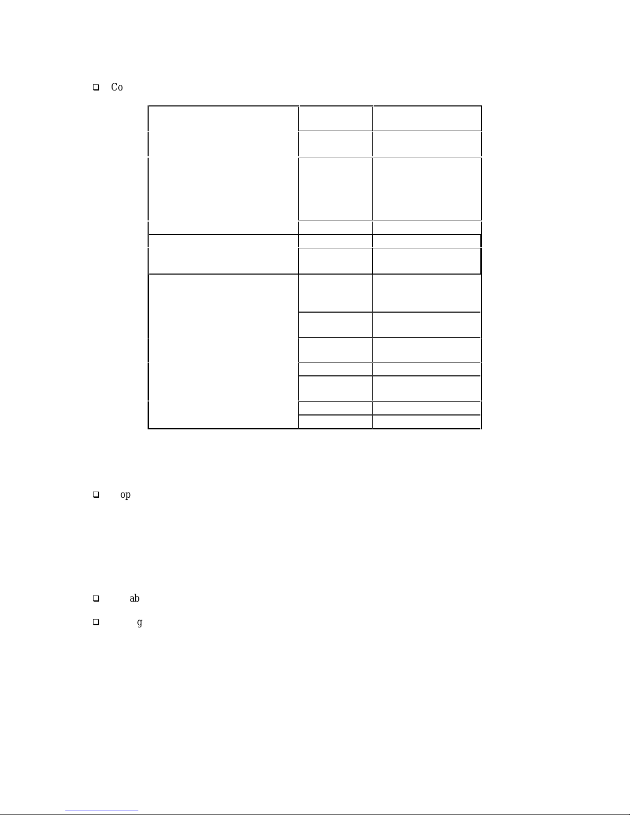
Installation Components
Table 1. Installation Components
Descr iption Function
i-Series Gateway
Provided
W/
Gatew ay
9
Universal Power Cord 120 VAC outlet
DB-9 RS232 Serial Cable (6 foot)
Mounting Hardware To attach brackets for rack mount
Mounting Brackets (2) For rack mounting
RS-530 type cable for high-speed links to
CSU/DSU or TA
System Administrator’s Guide The complete guide for the i-Series
Quick Installation Guide The condensed installation guide
RS-232, DB-25 to DB-9 modem cable
[male-male]. Note: This is a custom made cable.
50 pin cables with RJ-21 connectors.
Note: RJ21 cables, connecting blocks and
network cables may be ordered through NEC by
calling 1-617-454-6100.
Punch down blocks
Console port to PC for system
administration
For connecting WAN ports on i-Series
Gateway to CSU/DSU or TA
Gateway.
For connecting the i-Series Gateway to a
modem for remote configuration.
Telephony interface between the punch
down blocks and the i-Series Gateway.
(See page 6.)
Provides the interface between the RJ-21
connector and the PBX.
Parts not provided with the i- Series Gateway
Digital telephones and communication line cords are NOT supplied with this system.
Note: Use two-wire digital telephones only.
9
9
9
9
9
9
9
Optional
Needed
but not
supplied
Needed
but not
supplied
i-Series Gateway Page 4 G-6000G-SKE, Rev AA
Page 5
Typical Installation
Figure 1 shows a typical i-Series Gateway installation.
Figure 1. Typical Installation
RJ-21
(up to 12 Ports
per unit)
Punch Bloc k s
Cross-C onnect
Wires
RJ-21
(up to 12
Ports)
i-Series Gatew ay
PB X
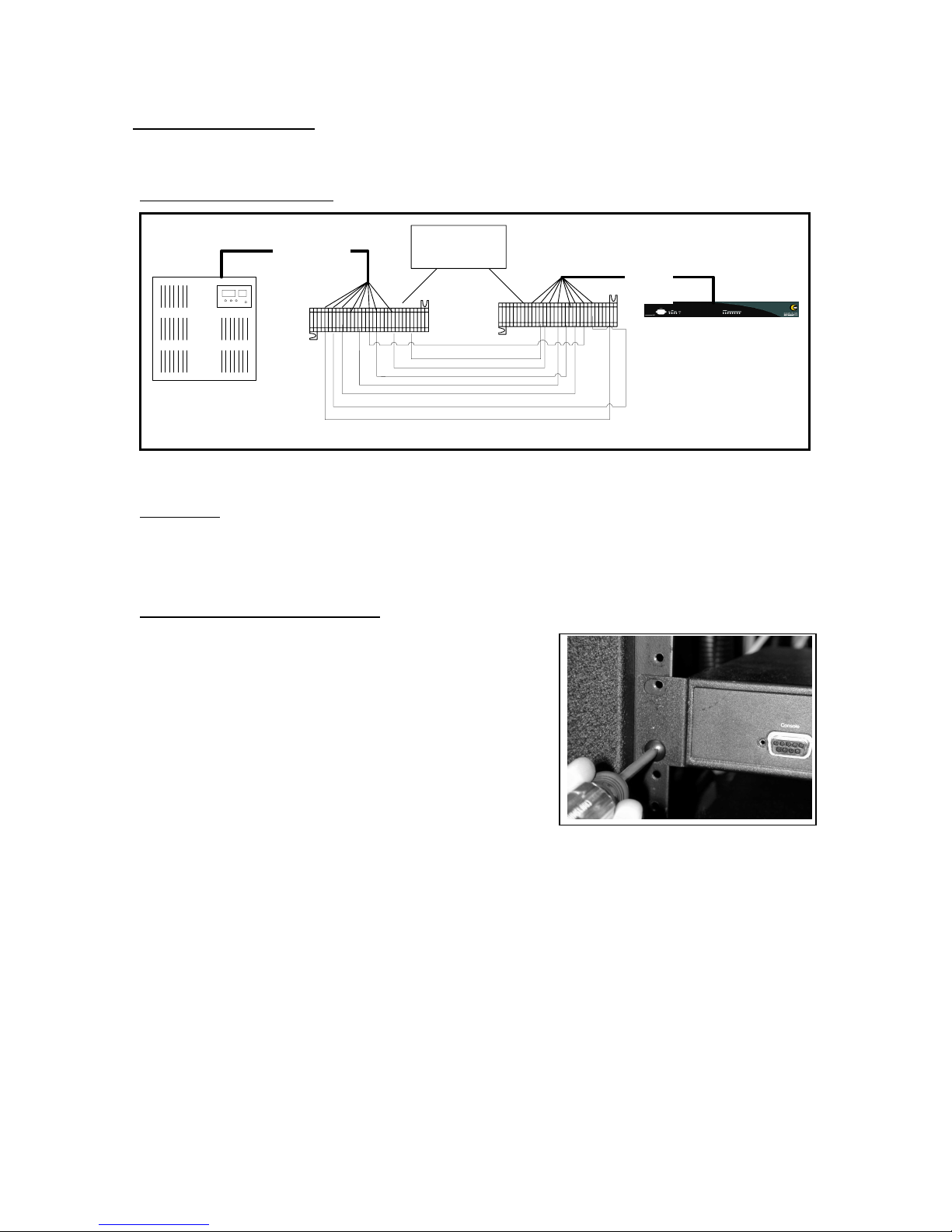
0RXQWLQJ
You can mount the i-Series Gateway in a standard 19-inch communication rack using the brackets provided
(Figure 2) or you can simply place it on a shelf within the rack.
Figure 2. Securing the unit to a rack
i-Series Gateway Page 5 G-6000G-SKE, Rev AA
Page 6
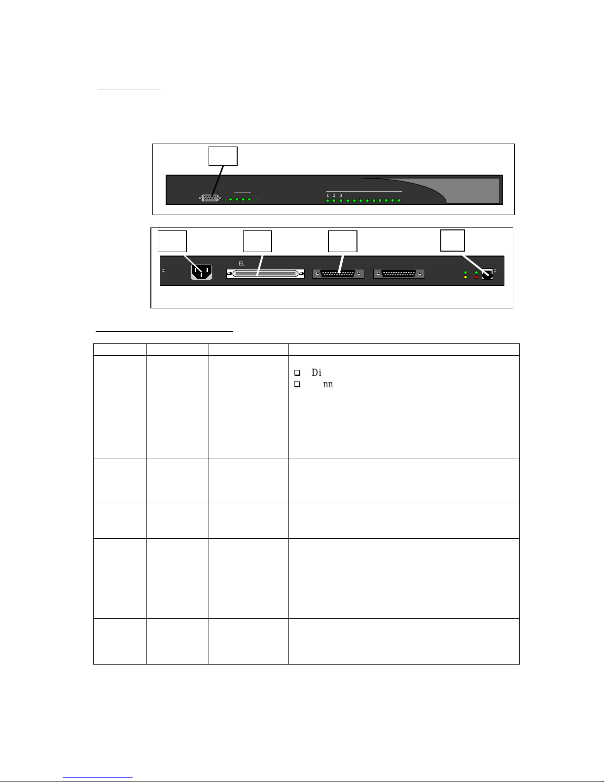
&RQQHFWLRQV
The i-Series Gateway requires connections A through E as shown below.
Front of Unit
A
Console
WAN
PW R 1 32
Reset
Port Status
31 2 8 9 10 11 127654
Back of Unit
B C D
100-240 V ~ 0.8A 50-60 HZ
TELEPHONY INTERFACE
WAN 1
E
WAN 2
0
Table 2. PBXtender Connections
Letter Label Cable Type Description
A Console DB-9 Connect to a PC for administration in two ways:
Direct serial connection to a PC.
Connect to a modem for remote access.
(See page 14 for modem installation and setup.)
Note: Set the COM port as follows; Baud rate: 9600,
Databits: 8, Parity: none, Stopbits: 1,
Software flow control: XON/XOFF
B - Power Connect to a 120VAC outlet.
Connect as the last step. (See page 8.)
C Telephony
Interface
RJ 21 Wire to a punchdown block and then to the PBX.
(See Table 3, page 7.)
D WAN1 DB 25, serial,
straight-through
Used for a synchronous or asynchronous-serial
connection. Connect to a TA, CSU/DSU, or other
network devi ce.
Note: An RS-530 type cable or DB-25 to M34 cable
should be used for high-speed links to V.35 equipment.
E LAN RJ 45 Ethernet Used for Telnet management or for connecting the unit
to the LAN for use in Voice over IP (RVP_IP)
applications.
LNK
CLN
XMT LNK
RCV CLN
i-Series Gateway Page 6 G-6000G-SKE, Rev AA
Page 7
Telephony Wiring
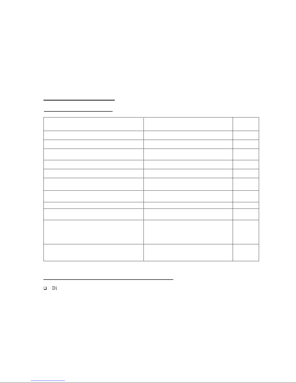
Table 3. Pin Assignments (25- P air Cable)
Pin Cable
Pair
26
1
28
3
30
5
32
7
Wire Color Abbreviations:
BK=Black, BR=Brown, RD=Red, OR=Orange, YL=Yellow, GN=Green, BL=Blue, VI=Violet, WH=White
SL=Slate
WH/BL
BL/WH
WH/GN
GN/WH
WH/SL
SL/WH
RD/OR
OR/RD
Port Pin Cable
Pair
1
2 36
3 38
4 40
34
9
11
13
15
RD/BR
BR/RD
BK/BL
BL/BK
BK/GN
GN/BK
BK/SL
SL/BK
Port
5 42
6 44
7 46
8 48
Pin Cable
17
19
21
23
Pair
YL/OR
OR/YL
YL/BR
BR/YL
VI/BL
BL/VI
VI/GN
GN/VI
Port
9
10
11
12
VT-100 Setup
Procedure
1. Make sure the i-Series Gateway is connected as shown on page 6.
2. You must use a communications package — for example, HyperTerminal — to configure and test the
i-Series Gateway. Attach one end of the RS-232 cable to your PC COM1 port and the other end to the
Console port connector on the front of the i-Series Gateway.
3. Set up HyperTerminal as follows:
Access: Start button > Programs > Accessories > HyperTerminal folder > HyperTerminal icon.
a
Type PBXgateway and click OK.
b
Within HyperTerminal go under File Properties and then select Connect using = Direct to COM1.
c
Select Configure and then set the parameters to 9600, 8, none, and Xon/Xoff and click OK.
d
Select the Settings tab and configure Emulation to VT100, then click OK.
e
4. Go to Power-Up sequence on the next page.
i-Series Gateway Page 7 G-6000G-SKE, Rev AA
Page 8

Power-Up
1. Once the VT-100 program is set up, plug the unit into an AC outlet. The device begins a series of selfdiagnostic tests, which are displayed as a series of LED flashes.
AC Power LAN Connection
Back of Unit (For a VOIP connection, see notes below.)
LAN Notes:
2. Once the power-up sequence is finished, the state of the following LEDs should be Green.
PWR and WAN 1 (Connected) Ports
Front of Unit
3. Go to Basic Configuration on the next page.
100-240 V ~ 0.8A 50-60 HZ
TELEPHONY INTERFACE
WAN 1
WAN 2
ANALOG LAN
LNK
XMT LNK
CLN
0
RCV CLN
The state for the LEDs labeled XMT (Transmit), RCV (Receive), and CLN (Collision) varies depending
on the status of the network. These LEDs are not critical for verifying the "Power-up Sequence".
LNK LED should be solid green.
If you connect an i-Series Gateway to an IP network, the unit requires an assigned IP address.
The Ethernet port on the Gateway operates only on 10-megabit Ethernet networks. It does not support
100 megabits.
LED States:
PWR: Solid Green
WAN1: Solid Green (Ready) if a synchronous device is connected to WAN 1.
Solid Orange (Ready) if an asynchronous ISDN TA is connected and accepting
commands (but there is no link up- in Call Suspend mode or have not dialed it yet).
Port LEDs: Solid Green if connected properly to PBX.
IMPORTANT: If any of the LEDs DO NOT power as explained, refer to the System
Administrator’s Gu ide for troubleshooting information.
Console
WAN
PW R 1 32
Reset
Port Status
31 2 8 9 10 11 127654
On initial power-up (or before the config file has been changed) the Management Interface (MI)
displays the following prompt.
If the i-Series Gateway is powered up
Press “Enter” to start the i-Series Gateway shell…..
prior to opening the terminal program,
this message will not appear.
Do you want to run the “Setup Wizard”
If you type “Yes”, the wizard asks a series of configuration questions. (See page 16.)
If you type “NO”, you enter the main MI.
LNK
CLN
i-Series Gateway Page 8 G-6000G-SKE, Rev AA
Page 9

Basic Configuration
1. Press Enter. The Welcome Screen of the MI is displayed.
(See Figure 3.)
Figure 3. Welcome Screen
IMPORTANT TERMINAL SETTINGS
The MI requires a screen size of 24 lines X 80 columns. Make sure the Welcome Screen
is bordered on all four sides with a # symbol, as shown in Figure 3.
To enlarge the screen (within the VT-100 application)
Click any corner of the screen.
Drag the screen to enlarge.
Check that the screen is bordered by “#” symbols.
2. Press any key to continue. The Main Menu will appear.
3. If you already familiar with using the MI proceed to the next page for information on setting the
parameters for different Installation Environments.
or
4. Press F1 for the MI Help Screen that provides basic information for navigating through the interface.
i-Series Gateway Page 9 G-6000G-SKE, Rev AA
Page 10

Installation Environments
Introduction
Which type
of Network
Device do
you have?
This section of the guide provides the necessary information to configure the i-Series
Gateway using the MI. The units are programmed at the factory with “default” settings
providing basic parameters to accommodate most network environments.
Before beginning the configuration process, it is necessary to identify the type of
network device connected to the i-Series Gateway. Once you know the connection type,
use Table 4, below, to find the appropriate configuration checklist.
Table 4. Network devices
To configure the i-Series Gate way with …..
A Synchronous-Serial device – V.35,
RS-232, RS-530 via WAN Port
(RVP_Direct)
An Asynchronous -serial device via WAN
Port(s) 1 or 2
(RVP_Direct) using RS-232 Protocol.
An IP* device – via Ethernet port
(RVP_IP)
* IP-based products from NEC America,
Inc. utilize Voice over IP (VoIP) technology
to deliver remote voice solutions. The voice
quality of these solutions is depend e nt on
variables such as available bandwidth,
network latency and Quality of Service (QoS)
initiatives, all of which are controlled by the
network and Internet Service Providers.
Because these variables are not in NEC
America, Inc. control, it cannot guarantee
the performance of the user’s IP-based
remote voice solution.
See page…..
11
12
13
i-Series Gateway Page 10 G-6000G-SKE, Rev AA
Page 11

6\QFKURQRXV6HULDO'HYLFH593B'LUHFW
Introduction
Figure 4. RVP_Direct Typical Installation
This section of the guide provides the necessary information to configure the i-Series
Gateway for connection to a synchronous-serial device. The units are programmed at
the factory with “default” settings providing basic parameters to accommodate many
network envi ronments.
Router
i-Series Gatew ay
Public
Punch Block
PBX
C orporate Facility
Router
DSU/CSUDSU/CSU
i-Series 6000
Extender
Punch Block
Branch Office
Prerequisites for Configuration
Both units must be installed properly and the network link between both devices must be operational.
Basic Configuration
Table 5. RVP_Direct Configuration Steps
You must ….……
to………… Default settings Refer to Syste m
Administrator’s Guide
Set the Telephone Port
compression algorithm
Provide adequate bandwidth
for all users.
for all active telephone
ports.
Enable/Disable WAN
ports
Enable WAN ports to
connect to network devic e.
Set the Sync Rate of the
WAN port.
Set the mode (interface
type) of the WAN port
(v.35, RS-232, RS-530).
Increase Jitter Delay
(for Frame Relay and
Async installs only).
Match the data rate (sync
rate) of the network device.
Match the interface type of
the networ k device.
Match network
characteristics of the Frame
Relay network.
i-Series Gateway Page 11 G-6000G-SKE, Rev AA
ADPCM 32 (on
all telephone
ports)
Chapter 4 - Port set u p,
Setting Voice
Parameters, page 61.
WAN 1 - Enabled Chapter 4 - WAN set up,
page 72.
512,000 kbps Chapter 4 - WAN set up,
page 74.
V.35 Chapter 4 - WAN set up,
page 80.
0 Chapter 4 - Setting Voice
Parameters; page 62.
Page 12

$V\QFKURQRXV6HULDO593B'LUHFW
Introduction
Figure 5. Async Connections
This section of the guide provides the necessary information to configure the
i-Series Gateway for connection to an asynchronous-serial device. The units are
programmed at the factory with “default” settings providing basic parameters to
accommodate many network environments.
i-Series Gatew ay
ISDN
ISDN TA
Punch Block
PBX
Corporate Facility
ISD N TA
Prerequisites for Configuration
The i-Series Gateway (at the corporate site) and the i-Series 6000TM Extender (at the branch office)
must be installed properly and the network link between both devices must be operational.
The network administrator must assign an IP address for both units in order to configure and test them
over a LAN or WAN.
Basic Configuration
Table 6. Configuration Steps
You must … to… Default settings Refer to System
Administrator’s
Guide
Enable the WAN port. Enable WAN functions WAN 1 Chapter 4, Enabling
WAN Port, page 73.
Set the mode (interface
type) of the WAN port.
Set the Async parameters
for the selected WAN port.
Set the Jitter Delay and
Compression settings.
Match the interface type
of the network device.
Match the settings for the
device being used.
Match the settings for the
device being used.
V.35 Chapter 4, Setting the
Mode, page 80.
- Chapter 4, Setting
ASYNC Parameters,
page 76.
- Chapter 4, Setting Jitter
and Compression, page
79.
i-Series 6000
Extender
Punch Block
i-Series Gateway Page 12 G-6000G-SKE, Rev AA
Page 13

,3'HYLFH593B,3
IP-based products from NEC America, Inc. utilize (VoIP technology to deliver remote voice
solutions. The voice quality of these solutions is dependent on variables such as available bandwidth,
network latency and QoS initiatives, all of which are controlled by the network and Internet Service
Providers. Because these variables are not in NEC America, Inc. control, it cannot guarantee the
performance of the user’s IP-based remote voice solution.
Figure 6. Typical Installation
R outer
LAN
i-Series 6000
Extender
Punch Block
i-Series 4000
Extender
Branch Office
Introduction
LAN
i-Series Gatew ay
Router
Punch Block
PBX
Corporate Facility
IP Network
This section of the guide provides the necessary information to configure the
i-Series Gateway for conne ction over an IP network.
Prerequisites for Configuration
Both units must be installed properly and the network link between both devices must be operational.
The network administrator must assign IP address i nformation for both Gatewa y and Remote units.
The network administrator must provide the remote users with User ID’s and Connect P asswords (if
assigned).
Basic Configuration
Table 7. Basic Configuratio n Steps
You must ….…… to………… Default settings Refer to System
Set the Telephone Port
compression method
Provide adequate bandwidth
for all users.
for all active telephone
ports.
Disable WAN ports Disable WAN ports that are
unnecessary for RVP_IP.
Tune Jitter Delay &
Packet Size
Set IP parameters;
9IP Address
9Subnet
Tune voice parameters to
match IP N etwork
characteristics.
Allow the i-Series Gateway
to communicate over the IP
network.
9Default Router
i-Series Gateway Page 13 G-6000G-SKE, Rev AA
ADPCM 32 (on all
telephone ports)
WAN 1 – Enabled
WAN 2 -Disabled
Jitter Delay: 0
Packet Size: 2
None Chapter 4 - Setting IP
Admin. Guide …….
Chapter 4 - Port set u p,
Setting Voice
Parameters; page 61.
Chapter 4 - WAN set
up, page 73.
Chapter 4 - Setting
Voice Parameters; page
61
Parameters; page 81
Page 14

Dial-Up Management Console
Introduction
The MI includes Zmodem functionality for the DB-9 dial-up management console port. An external
modem attached to the DB-9 port (not included with unit) is required to dial into the i-Series Gateway
management console interface. This console interface allows remote dial-up access using Zmodem
protocol to the management console. (Refer to Appendix A.)
When a dial-up connection is established to the MI of one unit, it is possible to “Rlogin” to other connected
units to access the MI of those units when the network connection between units is not functioning. This
connection allows access to all features and functions of the MI and the ability to configure, monitor, and
troubleshoot the unit from a remote location. (See the figure on page 6.)
Required Equipment
• Modem (not included with unit)
• Direct analog telephone line for connection to the modem
• RS-232, DB-25 to DB-9 modem cable [male-male] (See Table 8, below, for pinout information.)
• P r oper ly installed i-Series Gateway unit
Pinout Information
Table 8. Modem Cable Pinouts
DB-25 Male
Pin Function Pin Function
2 Tx 2 Rx
3 Rx 3 Tx
7 Common 5 Common
8 DCD 7 RTS
20 DTR 8 CTS
DB-9 Male
i-Series Gateway Page 14 G-6000G-SKE, Rev AA
Page 15

Setup Wizard
The i-Series Gateway provides a console setup wizard that guides a user through most of the required
programming/configuration required to complete initial setup of the units, via the VT100 management
console accessed through the DB-9 management port. You can use the MI to set parameters not
configurable through the wizard.
Access the setup wizard through the console MI, requiring a PC to connect to the unit (i-Series Gateway)
via the DB-9 console port. The wizard queries the user on the basics of the particular configuration, and
uses this information to establish the initial configuration pro gramming.
Standard Console UI vs. the Setup Wizard
When a unit is first powered up, it checks a Setup Wizard flag. If the flag is set, the standard console UI is
displayed. If the flag is not set, the system asks you to run the Setup Wizard. After this initial p rompt the
Setup Wizard flag is set. This prevents the unit from asking you to run the Wizard again. You can also
access the Setup Wizard through the console MI if you want to run it later.
How to access the Setup Wizard through the MI
Path: Gateway->Utilities -> Setup Wizard
i-Series Gateway Page 15 G-6000G-SKE, Rev AA
Page 16

Telnet Connection
,QWURGXFWLRQ
You can configure the i-Series Gateway using a Telnet session over the existing LAN connection. A
maximum of four Telnet connections can exist per unit at one time.
IMPORTANT:
• You must co nfig ure all IP parameters before you can establish a Telnet session to a unit.
• The i-Series Gateway must be powered up and online. (See Power-up procedure on page 8.)
3URFHGXUH
1. On a computer running Windows, open the Telnet application by selecting Start/Run from the
desktop.
2. Enter Telnet command along with the IP address assigned to the unit. (See below.)
Telnet address
3. Click OK.
The MI Welcome Screen is displayed. (See page 9.)
HTML Interface
Introduction
You can configure the i-Series Gateway using a standard Web server over an existing LAN connection.
This feature provides the system administrator complete management capabilities as well as status
information for both WAN and PORT connections.
IMPORTANT:
• You must configure all IP parameters for the i-Series Gateway before the Web server session can be
established.
• The i-Series Gateway must be connected to the LAN via the LAN port.
• The i-Series Gateway must be powered up and online. (See Power-up procedure on page 8.)
Procedure
1. Access the MI using a Telnet session or via the Console Port.
i-Series Gateway Page 16 G-6000G-SKE, Rev AA
Page 17

2. Access the Web Server parameter using the following path:
Configuration->IP->LAN->Web Server
3. Select YES for Enabled. Set the Timeout to 30.
4. Save the settings and Log out of the MI.
5. Open any web browser from your PC.
Example
: Windows Internet Explorer (version 5.X or higher)
6. At the http:// prompt type in the IP Addr ess of the i-Series Gateway as shown below.
7. The HTML pop-up window will appear.
IMPORTANT
INSTRUCTIONS
i-Series Gateway Page 17 G-6000G-SKE, Rev AA
Page 18

8. Double click the Start Managing the Device link.
9. The Main menu is displayed.
Power LED WAN LEDs Port LEDs
Menu Selections
LED States:
PWR: Solid Green
WAN1: Solid Green (Ready) if a synchronous device is connected to WAN 1.
Solid Orange (Ready) if an asynchronous ISDN TA is connected and accepting
commands (but there is no link up- in Call Suspend mode or have not dialed it yet).
Port LEDs: Solid Green if connected properly to PBX.
10. The MI is now accessible for complete i-Series Gateway configuration.
i-Series Gateway Page 18 G-6000G-SKE, Rev AA
Page 19

Optional Configur ation
The i-Series Gateway MI has optional configuration parameters providing the following capabilities:
1. Admin Password – If configured, this option restricts access to the i-Series 6000 Extender MI, by
requiring a password for entry. This Admin Password MUST be entered before any configuration
parameters are changed.
Note: Both units have their own separate Admin Passwords.
2. Connect Password – This option provides a secure WAN link between the units. If configured, a
Connect Password is required to connect to the alternate module.
Note: Refer to the System Administrator’s Guide (Issue AC) for more information on configuring these
options.
i-Series Gateway Page 19 G-6000G-SKE, Rev AA
Page 20

Appendix A
Setting the Modem DIP switches
The modem has a DIP switch located on the outside of the unit. This switch contr ols modem functionality
and must be set to the guidelines specified below prior to installin g the modem.
Function Setting Description
DTR Normal mode ON Computer must provide DTR signal for modem to
accept commands: dropping DTR terminates a call.
Verbal result codes ON -
Display result codes OFF -
No echo on offline commands OFF Suppress echo.
Auto answer ON ON Modem answers on first ring, or higher.
Carrier Detect (CD) normal ON Modem sends CD signal when it connects with
another modem, drops CD on disconnect.
The following table shows the settings required for a US Robotics 33.6 Fax modem (not supplied).
(US Robotics 33.6 Fax Modem) D IP Switch Settings
Function Setting Description
DTR Normal mode ON Computer must provide DTR signal for modem to accept
commands: dropping DTR terminates a call.
Verbal result codes ON Display result codes OFF No echo on offline commands OFF Suppress echo.
Auto answer ON ON Modem answers on first ring, or higher.
Carrier Detect (CD) normal ON Modem sends CD signal when it connects with another
modem, drops CD on disconnect.
The following table shows the settings for a Sportster 33.6 modem.
Switch
Position
1 UP DTR Normal mode Computer must provide DTR signal for modem
2 UP Verbal result codes 3 DOWN Disp lay result codes 4 DOWN No echo on offline commands Suppress echo.
5 UP Auto answer ON Modem answers on first ring, or higher.
6 UP Carrier Detect (CD) normal Modem sends CD signal when it connects with
7 DOWN Load factory defaults Loads generic template from read only memory
8 DOWN S mart mode Enable recognition (Smart mode).
Setting Function Description
to accept commands: dropping DTR terminates
a call.
another modem, drops CD on disconnect.
(ROM).
i-Series Gateway Page 20 G-6000G-SKE, Rev AA
Page 21

Installing the modem at the i-Series Gateway Site
Procedure
1. Connect the analog telephone line to the modem.
2. Plug the modem cable (provided with the unit) into the back of the modem.
3. Power-up the modem. The modem runs a series of self-diagnostic tests.
4. Plug the other end of the modem cable into the port labeled “Console port” on the front of the i-Series
Gateway.
5. Power-up the i-Series Gateway unit. The modem status LED for “Data Terminal Ready” should be
RED indicating the modem is ready to receive data.
Note: Refer to the Modem User’s Guide for specific LED information.
i-Series Gateway Page 21 G-6000G-SKE, Rev AA
Page 22

NEC America, Inc., Corporate Networks Group
4 Forest Parkway, Shelton, CT 06484
Tel: 800-365-1928 Fax: 203-926-5458
cng.nec.com
Other Important Telephone Numbers
Sales: 203-926-5450
Customer Service: 203-926-5444
Customer Service FAX: 203-926-5454
Technical Service: 203-925-8801
Discontinued Product Service: 900-990-2541
Technical Training: 203-926-5430
Emergency Technical Service (After Hours) 203-929-7920
(Excludes discontinued products)
i-Series Gateway Page 22 G-6000G-SKE, Rev AA
 Loading...