

Page 1

()
■■■■■■■
■■■■■■■
■■■■■■■
■■■■■■■
■■■■■■■
■■■■■■■
Server HX4500
User's Guide
■■■■■■■
■■■■■■■
■■■■■■■
■■■■■■■
■■■■■■■
■■■■■■■
■■■■■■■
■■■■■■■
Page 2

xxx
Page 3

Server HX4500
()
■■■■■■■
■■■■■■■
■■■■■■■
■■■■■■■
■■■■■■■
■■■■■■■
User's Guide
■■■■■■■
■■■■■■■
■■■■■■■
■■■■■■■
■■■■■■■
■■■■■■■
■■■■■■■
■■■■■■■
Page 4

Proprietary Notice and Liability Disclaimer
The information disclosed in this document, including all designs and related materials, is
the valuable property of NEC Computer Systems Division, Packar d Bell NEC, Inc.
(hereinafter “NEC CSD”) and/or its licensor s. NEC CSD and/or its licensors, as
appropriate, reserve all patent, copyright and other proprietary rights to this document,
including all design, manufacturing, reproduction, use, and sales rights thereto, except to
the extent said rights are expressly granted t o others.
The NEC CSD product(s) discussed in this document are warranted in accordance with the
terms of the Warranty Statement accompa nying each product. However, actual
performance of each such product is dependent upon factors such as system configuration,
customer data, and oper ator control. Since imple ment ation by customers of each product
may vary, the suitability of specific pro duct configurat ions and applications must be
determined by the customer and is not warrant ed by NEC CSD.
To allow for design and specification improve ment s, the information in this document is
subject to change at any time, without notice. Reproduction of this document or portions
thereof without prior written approval of NEC CSD is prohibited.
Trademarks
INTEL is a registered t r ademark of Inte l Corpo r at ion.
MS-DOS is a registered tr ademark of Microsoft Corporation.
Pentium is a registered trademark of Inte l Corpor ation.
All other product, brand, or trade names used in this publication are t he trademarks o r
registered trademarks of their respective trademark owners.
PN: 456-00005-000nnnnnnnnnnnnnnnnnn12/98
Copyright 1998
NEC Computer Systems Division
Packar d Bell NEC, Inc.
1 Packar d Bell Way
Sacramento, CA 95828-0903
All Rights Reserved
Page 5

Contents
Proprietary Notice and Liability Disclaimer
Regulatory Information
Using This Guide...................................................vii
Text Conventions............................................................................ viii
Related Documents.............................................................................ix
Safety Notices.....................................................................................x
Safety Notices for Users Outside of the U.S.A. and Canada...........xi
Care and Handling.............................................................................xii
System Overview.................................................. 1-1
Overview......................................................................................... 1-2
System Feature Summary........................................................... 1-3
Expanding the Server as Needs Grow......................................... 1-4
Configuration Constraints........................................................... 1-4
Chassis............................................................................................ 1-5
Status LED Indicator Descriptions.............................................. 1-6
Opening the Front Doors............................................................ 1-7
Chassis Features and Controls.....................................................1-9
System Board Features.................................................................. 1-11
Processor.................................................................................. 1-16
Memory.................................................................................... 1-16
Bus Master I/O Expansion Slots............................................... 1-16
Real-Time Clock/Calendar ....................................................... 1-16
BIOS........................................................................................ 1-16
Video....................................................................................... 1-17
SCSI Controller........................................................................ 1-17
Peripheral Controller................................................................ 1-17
External Device Connectors...................................................... 1-17
Keyboard and Mouse ................................................................ 1-17
Fans......................................................................................... 1-18
Peripheral Devices......................................................................... 1-18
Ultra2 Wide SCSI-2 Hard Drive Bays....................................... 1-18
Removable Media Drive Bays .................................................. 1-19
System Power................................................................................ 1-20
Software Locks via the BIOS Setup............................................... 1-20
Setting Up Your System ....................................... 2-1
Selecting a Site................................................................................ 2-2
Unpacking the System..................................................................... 2-3
Moving the System to the Site......................................................... 2-3
Getting Familiar With the System.................................................... 2-4
Making Connections........................................................................ 2-4
Connecting the Power Cords............................................................ 2-6
Powering On Your System.............................................................. 2-7
Contents iii
Page 6

Configuring Your System......................................3-1
Configuring Your System................................................................ 3-2
Resource Configuration Utility (RCU)............................................. 3-2
Using the RCU ........................................................................... 3-3
RCU Command Line Parameters................................................ 3-5
RCU Configuration Settings....................................................... 3-5
ISA Board Configuration............................................................ 3-6
BIOS Setup Utility .......................................................................... 3-8
Using the BIOS Setup Utility...................................................... 3-8
BIOS Setup Configuration Settings............................................. 3-9
Exiting BIOS Setup.................................................................... 3-9
SCSISelect Utility......................................................................... 3-14
Using the SCSISelect Utility..................................................... 3-14
SCSISelect Configuration Settings............................................ 3-15
Exiting SCSISelect................................................................... 3-15
Configuring the RAID Controller .................................................. 3-17
Configuring System Jumpers and Switches.................................... 3-18
Before You Begin..................................................................... 3-18
Configuring I/O Riser Board Function Select Switches............. 3-18
Configuring CPU Base Board Function Select Switches........... 3-20
Configuring Memory Board Function Jumpers......................... 3-21
Configuring System I/O Board Switches and Jumpers............... 3-21
Setting Switches and Jumpers................................................... 3-24
BIOS........................................................................................ 3-25
Updating the BIOS .............................................................. 3-25
Changing the BIOS Setup Language.................................... 3-26
Resetting the CMOS NVRAM.................................................. 3-27
Clearing and Changing the Password........................................ 3-28
Upgrading Your System ........................................4-1
Precautions...................................................................................... 4-4
Preparing Your System for Upgrade................................................ 4-6
Equipment Log........................................................................... 4-6
Removing the Front Doors..........................................................4-7
Installing the Front Doors........................................................... 4-7
Removing the Top Cover and Side Panels................................... 4-8
Installing the Top Cover and Side Panels.................................. 4-10
Modifying the System I/O Board................................................... 4-11
Installing Video Memory.......................................................... 4-11
Replacing the Non-Volatile Memory ........................................ 4-12
Replacing the Real-time Clock Battery..................................... 4-13
DIMMs......................................................................................... 4-15
Installing DIMMs..................................................................... 4-15
Removing DIMMs ................................................................... 4-17
Processors..................................................................................... 4-18
Installing a Processor Cartridge ................................................ 4-19
Removing a Processor Cartridge or Termination Board............. 4-22
Option Boards............................................................................... 4-23
Installation Considerations........................................................ 4-23
Controller/Adapter Hardware Configurations............................ 4-25
Installing an Option Board........................................................ 4-26
Removing an Option Board...................................................... 4-28
Power Supply................................................................................ 4-29
iv Contents
Page 7

Installing a Power Supply......................................................... 4-29
Removing a Power Supply........................................................ 4-30
Hot-Swapping a Power Supply ................................................. 4-30
Removable Media Devices ............................................................ 4-31
Installing a 5 1/4-Inch Device or 3 1/2-Inch Diskette Drive....... 4-33
Removing a 5 1/4-Inch Device or 3 1/2-Inch Diskette Drive ..... 4-37
Hard Disk Drives........................................................................... 4-38
Installing a Hard Drive............................................................. 4-39
Removing a Hard Drive............................................................ 4-42
Hot-Swapping a Hard Drive...................................................... 4-43
Problem Solving ...................................................5-1
Resetting the System........................................................................ 5-2
Troubleshooting Checklists.............................................................. 5-2
Initial System Startup................................................................. 5-2
Running New Application Software............................................ 5-3
After System Has Been Running Correctly................................. 5-4
Additional Troubleshooting Procedures ........................................... 5-5
Error Checking........................................................................... 5-5
Troubleshooting Guide............................................................... 5-5
Preparing the System for Diagnostic Testing.......................... 5-5
Monitoring POST While Running..........................................5-6
Verifying Proper Operation of Key System Indicators............5-6
Confirming Loading of the Operating System ........................ 5-7
Specific Problems and Corrective Actions ....................................... 5-7
Power LED Does Not Light........................................................ 5-7
System Cooling Fans Do Not Rotate........................................... 5-7
No Characters Appear On Screen................................................ 5-8
Characters are Distorted or Incorrect........................................... 5-9
Floppy Disk Drive Activity LED Does Not Light ....................... 5-9
Hard Disk Drive Activity LED Does Not Light........................... 5-9
Problems with Application Software......................................... 5-10
Error Messages.............................................................................. 5-10
Alarm Indication during POST................................................. 5-10
Alarm Indication during Operation........................................... 5-13
CPU Error Messages ........................................................... 5-14
Memory Error Messages...................................................... 5-14
Status LED.................................................................................... 5-15
System Cabling ....................................................A-1
Before You Begin............................................................................A-2
Static Precautions............................................................................A-2
RAID Configuration........................................................................A-3
Memory Configurations........................................B-1
Memory DIMM Configurations .......................................................B-2
Glossary
Equipment Log
Contents v
Page 8

vi Contents
Page 9

Contents vii
Page 10

Page 11

Using This Guide
This User’s Guide provides a quick reference to information about your
system. Its goal is to familiarize you with your system and the tasks
necessary for system configuring and upgrading.
This guide contains the following information:
Chapter 1, “System Overview” provides an overview of your
syste m and describes your system’s major system co mpo ne nts.
See this chapter to familiarize yourself with your system.
Chapte r 2, “Setting Up Your System” tells yo u how to select a
site, unpack the system, make cable connect ions, and power on
your system.
Chapt er 3, “Configuring Your System” tells you how to configure
the system and provides instructions for running the Resource
Configuration Utility, BIOS Setup Utility, and SCSISelect Utility.
It also provides information on system board jumper settings.
Chapter 4, “Upgrading Your System” provides you with
instructions for upgrading your system with additional processors,
optional memory, option cards, and peripheral devices.
Chap ter 5, “Pro blem Solving ” cont a ins helpful informa tion for
solv ing pr oblems that might oc cur with your syst e m.
Appendix A, “System Cabling” includes cabling information for
the onbo a rd SCSI co ntroller.
Appendix B, “Memory Configurat ions” defines the allowable
memory configurations for your system.
“Glossary” defines t he st andard acr onyms and technical ter ms
used in th is ma nu a l.
“Equipment Log” provides you with a sample equipment log for
documenting the system configuration and future updates you
may make to your system.
Using This Guide vii
Page 12
Text Conventions
This guide uses the following text c onventions.
War n ings, cautions, and not es have the following me anings:
Warnings alert you to situations that could result i n
serious personal injury or loss of life.
Cautions indi c ate situations that can damage the
system hardware or software.
Note:
Notes give important inf ormation about the
material being described.
Names of keyboard keys are printed as they appear on the
keyboard. For example, Ctrl, Alt, or Enter.
!
WARNING
!
CAUTION
T ext o r keystrok es that you enter appear as bo ldface type. For
example, type abc123 and press ENTER.
File names are pr inted in uppercase lett ers. For example,
AUTOEXEC.BAT.
viii Using This Guide
Page 13

Related Documents
In addition to this guide, the following system documentation is included
with your server either as electronic files on E
paper copy shipped with your server.
System Release Notes
Release Not es pro vide you with t he latest information about your
system. This infor mat ion was not avai lable at the time your user’s
guide was developed.
Getting Started Sheet
The Getting Started S heet prov ides several easy-to-follow steps to
become familiar with your server do cumentation and to complete
your inst a lla tion suc c es s fu l ly.
Net work Operating System Configuration Guide
This guide contains supp leme nt al instructions needed to insta ll
and configure your server Windows NT v4.0, Novell NetWare
v4.11, Santa Cruz Operation (SCO) OpenServer Re lease 5. 04, and
SCO UNIXWARE 7.0 Network Operating Systems. This
document is intended to complement the more detailed procedural
documents available from the vendor of the network operating
system.
XPRESSBUILDER
or as
Using This Guide ix
Page 14

Safety Notices
Caution: To reduce the risk of electric shock which co uld cause
per s onal injury, follow all safe ty no tices. The symbols shown are
used in your documentation and on your equipment to indicate
safety hazards.
Warning: Lith ium ba tte ries can be dangerous. Improper ha ndling
of lit h iu m bat t e r ies ma y re su lt in a n exp lo s io n. Dis pose o f lit hium
batteries as required by loca l ordinance or as normal waste if no
local ordinance exists.
Warning: The detachable power supply cord is intended to serve
as the disconnect device.
Warning: This equipment has two 3-wire, grounded power cords.
To prevent electrical hazards, do not remove or defeat t he ground
prong on the power cord. Replace the power cord if it gets
damaged. Contact your dealer for an exact replacement.
!
Warning: The DC push-button on/off switch on the front panel
does not turn off the syste m AC power. Also , +5vdc is present o n
the system board whenever the AC power cord is connected
between the system and an AC out let. Befor e doing the
procedures in this manual, make sure that your system is powered
off and unplug the AC power cord from the back of the chassis.
Failure to disconnect power before opening your system can result
in personal injury and equipment damage.
In the U.S.A. and Canada, each power cord must be a UL-listed
detachable power cord (in Canada, CSA-certified), type ST or SJT, 16
AWG, 3-conductor, provided with a molded-on NEMA type 5-15 P plug
cap at one end and a molded-on cord connector body at the other end.
The cord length must not exceed 9 feet ( 2.7 meter s).
x Using This Guide
Page 15

Outside the U.S.A. and Canada, the plug must be rated for 250 Vac, 10
amp minimum, and must display an international agency approval
marking. The cord must be suitab le for use in the end-user country.
Consult your dealer or the local electrical author it ies if you are unsure o f
the type of power cord to use in your country. The voltage change occurs
via a switch in the power supply.
Warning: Under no circumstances should the user attempt to
disassemble the power supply. The power supply has no userreplaceable parts. Inside the power supply are hazardous voltages
that can cause serious personal injury. A defective power supply
must be returned to your dealer.
Safety Notices for Users Outside of the U.S.A. and Canada
PELV (Protected Ext ra-Low Voltage) Integrity: To ensure the
extra-low voltage integrit y of the equipment, co nnect only
equipment with mains-protected electrically-compatible circuits to
the external port s.
Remote Earths: To pr event electr ica l shock, connect all loca l
(individual office) computers and computer support equipment to
the same electrical circuit of the building wiring. If you are
unsure, check the building wiring to avoid remote earth
conditions.
Earth Bo ndi n g : Fo r safe op er ation, only connect the equipment
to a building supply that is in accordance with current wiring
regulations in your countr y. In the U.K., those regu lations are t he
IEE.
Using This Guide xi
Page 16
Care and Handling
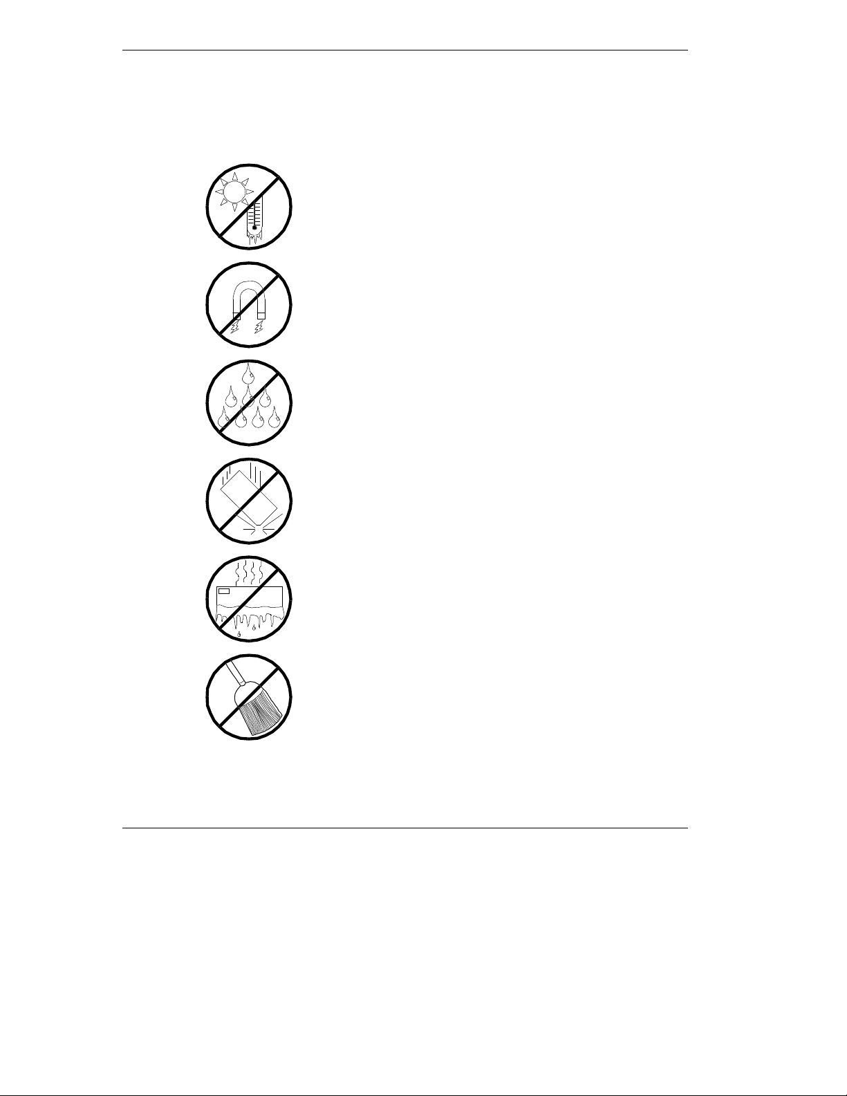
Use the following guidelines to pro p er ly handle and care for your
system.
Protect the system from extremely low or h igh
temperatures. Let the system warm (or cool)
to room temperature before using it.
Keep the system away from magnetic forces.
Keep th e system dry. Do n ot wash the
system with a wet cloth or pour fluid
into it.
Prot ect t he s ystem from bein g bum ped or
dropped.
xii Using This Guide
Check the system for con densa tion . If
condensation exists, allow it to evaporate
before powering on the system.
Keep th e system away fr om dust , sand,
and dirt.
Page 17

System Overview
Overview
Chassis
System Board Features
Peripheral Devic es
System Power
Software Locks via the BIOS Set up
1
Page 18

Overview
The server is a modular, multiprocessing server based on the Int el Pentium®
II Xeon chip set. The chip set incor po r ates a modular sca lea ble arc h itect ure that
integrates a 64-bit bus interface with three Peripheral Co mponent I nt er co nnect
(PCI) buses and an Indust r y Standard Arc h itect ure (ISA) bus. The architecture
supports Symmetrical Multiprocessing (SMP) and a variety of operating
systems. The chassis and system boards ar e designed to meet the needs of the
server marketplace.
The combination of comput ing performance, memory capacity, and integrated
I/O provides a high performance environment for many applications including
network servers and multi-user systems. The server is designed for use in
applications where downtime must be minimized. To this end, the server
includes or has the option to include the following.
Power system redundancy; in a system configured with redundant power
Self-c ontained power sup ply units tha t can b e easily insta lle d or removed
Hot-swap SCSI hard drive bays accessible from the front of the chassis; a
supplies, the system will continue to operate with a single power supply
failure.
from the back of the chassis.
failed drive can be removed, and a new drive installed without system
power being turned off.
High degree of SCSI hard disk fault tolerance and advanced disk array
management features through the use of RAID (Redundant Array of
Independent Disks) technology.
Hardware monitors (temperature and voltage) and software monitors to
indicate failure s.
E asy access to all parts for ser v ice.
1-2 System Overview
Page 19

System Feature Summary
A summary of the system features is included in Table 1-1.
Table 1-1. System Features
Feature Description
Modular board set System is intended for use with a modular board set based on Pentium II
Xeon processor technology; from one to four processors and up to 4 GB
of memo ry .
Add-in board support Rail and back panel slots support up to 11 add-in boards (two ISA and
nine PCI).
3 1/2-inch diskette drive 3 1/2-inch diskette drive is externally accessible.
One location for a 3 1/2-inch
removable media device
5 1/4-inch SCSI CD-ROM 5 1/4-inch CD-ROM drive is externally accessible.
Three locations f or 5 1/4 -
inch removable media
devices
12 locat ions f or 3 1/2-inc h
Ultra2 Wide SCSI-2 hard
drives
Hot swap-capable
backplane
Power supply From two to three 420 Watt autoranging power supplies are easily
Software: utilities, setup BIOS Setup, Resource Configuration Utility, and SCSISelect Utility. The
Security Mechanical: Key lock at the front door. One intrus ion se nsor for front door
One extern ally accessi ble 3 1/2-inch ha lf-heigh t bay is available for server
expansion.
Three externally accessible 5 1/4-inch half-height bays are available for
server expansion (diskette, CD-ROM, and/or tape drives).
Three hard disk drive cages; each holding up to four 3 1/2-inch hot-
swappable Ultra2 wide SCSI-2 hard drives. Each cage is secured behind
a metal EMI door; drives can be swapped in or out of the system without
powering it down. T he arr ay of drives allows eas y setup of RAID
applications.
A hot swap-capable backplane is part of each drive cage assembly for
SCSI hard drives. The backplane is designed for Ultra2 wide SCSI-2
devices that use the industry standard 80-pin Single Connector Attach
(SCA) connector. The backplane consists of a row of four drive
connectors.
removed/installed for service. In a three-supply system, the third supply is
redundant.
XPRESSBUILDER
E
CD-ROM contains the serve r management software.
to secure disk ette, hard disk, removabl e media devic e, pow er on/o f f
switch, reset switch, top cover, and left/right panel access. Three power
inter-lock sensors one on each side of the chassis and one on top of the
chassis. BIOS: Password enable.
CD-ROM contains the setup ut ilities a nd th e E SMPRO
System Overview 1-3
Page 20

Expanding the Server as Needs Grow
A typ ical mini mum sys te m config uration may includ e the following:
boa rd set co nsist i ng of sys te m I /O bo ard, CPU base bo ard w ith a
Pentium II Xeon processor, and a memory board
diskette drive and SCSI CD-ROM drive
three SCSI hard drive cages with one hard drive and a RAID contro ller
installed
ne t w o r k add - in bo a r ds
two 420 watt power supplies (an opt ional third power supply provides
redundant power)
onboard 2 MB video memory
system I/O board has two ISA slots and nine PCI slots for add-in boards.
The system I/O board also has a riser board for external I/O (serial,
parallel, video) interfaces.
chassis can hold six removable media drives: four 5 1/4-inch half-height
bays with a CD-R OM drive in s ta lle d in o ne bay; a nd t wo 3 1/ 2-inc h halfheight bays w ith a dis ket te dr ive installed.
As server/client needs grow, you can expand system processor capacity,
memory, drives, option boards, and the number of power supplies.
C PU base board ha s four slo ts fo r C PUs, for a configura ble ra nge of one,
two, three, or four processors.
Memory board supports 16 DIMM devices for up to a maximum memory
size of 4 GB.
System I/O board has eleven option board slots (two ISA and nine PCI).
C hassis can hold six re mova ble media drive s .
Three SCSI hard drive cages support up to 12 hot-swap bays for 3 1/2-
inch ultra wide SCSI-2 hard drives.
Confi gur a tion Cons tr ai nt s
The system has four 5 1/4-inch half-he ig ht ba ys access ib le fro m the front . These
bays are convenient for diskette, tape, and CD-ROM drives (removable media).
Because of the EMI generated by hard drives, the increased susceptibility to
ESD, and cooling requirements, hard drives should not be insta lled in the 5 1/4inch half- he ig ht bays.
1-4 System Overview
Page 21

Chassis
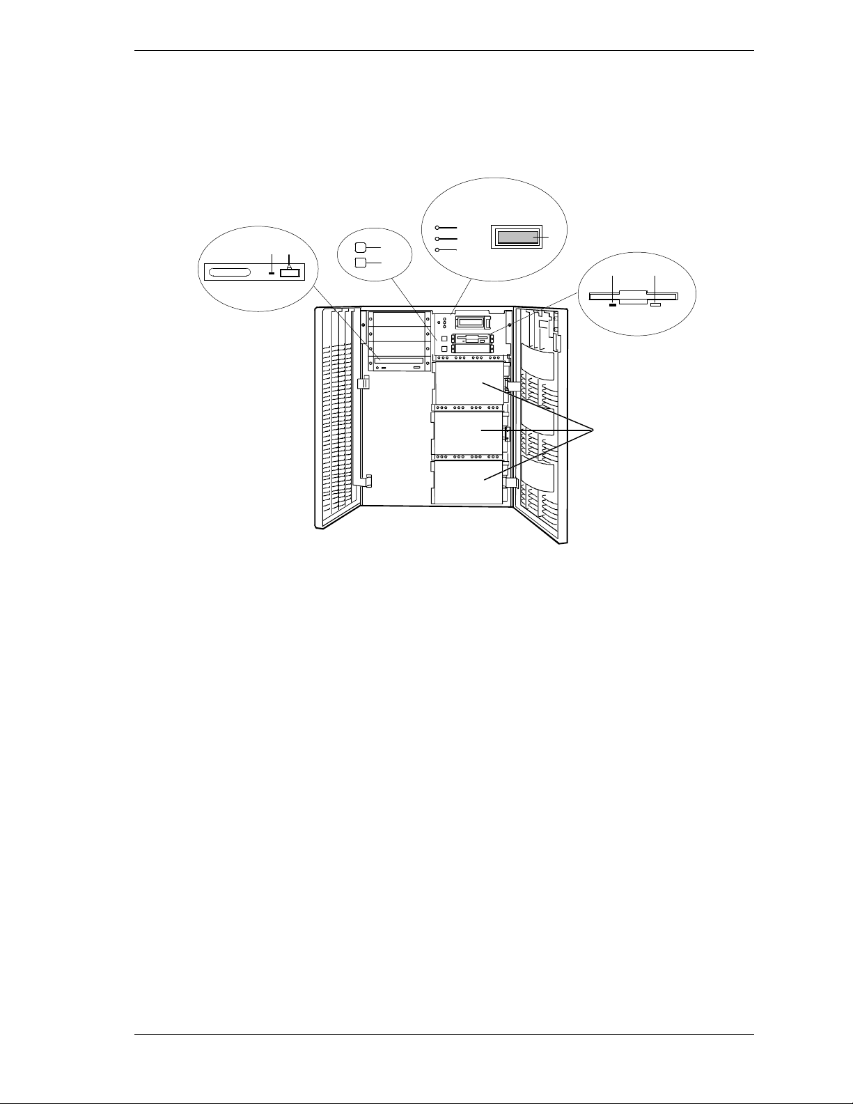
Figure 1-1 shows the server fro nt chassis features and controls.
A
B
C
FGH
3
POWER
STATUS
DISK
D
E
I
A
Power LED When green, power i s present in syst em . When off, power is
turned of f or power s ourc e is disrupt ed. See Table 1-1 f or a
list and description of the system LEDs.
B
Status LED
C
Disk LED
D
Key lock
E
LCD panel
F
Drive pr esent /pow er on
G
Drive acti v e
H
Drive faulty.
I
Casters (4) Used when moving the server. Fixed by the caster hol ders.
When green the syst em is OK. S ee Table 1-1 f or a li st and
description of the system LEDs.
When green, in ternal disk drives are being accessed. See
Table 1-1 for a list and description of the system LEDs.
Secures both front external doors.
Displays information about BIOS and system failures (error
and diagnostic information).
Each drive has three LEDs visible above the bay from the
front. See Table 1-2 for a list of SCSI disk drive status LED
indicators.
Figure 1-1. Front Chassis Features and Controls
System Overview 1-5
Page 22

Status LED In dicator Descr iptions
Table 1-2 lists the system status LED indicators along with a description of each
LED indicator. Table 1-3 lists the disk drive status LED panel indicators along
with a description of each LED indicator. Table 1-4 lists system status abnormal
conditions.
Table 1-2. System Status LED Indicators
LED Status Description Response
Power Off Power OFF None required (normal)
Green Power ON None required (normal)
Amber System power supply
failure
Status Off Power OFF None required (normal)
Green No alarms None required (normal)
Amber Abnormal condition
(see Table 1- 4)
Disk Off Not accessing disk drives None required (normal)
Amber Internal disk drive failure Check disk drive status LEDs
Green Accessing disk drives None required (normal)
Replace failed power supply module.
Check condition
Table 1-3. Disk Drive Status LED Panel Indicators
LED Status Description Response
Disk Drive
Present
Disk Drive
Activity
Off Disk drive not present None required (normal)
Green Disk drive present None required (normal)
Off Not accessing disk drive None required (normal)
Disk Drive
Status
1-6 System Overview
On Accessing disk drive None required (normal)
Off No alarms None required (normal)
Amb er Disk dr ive failure Replace d isk drive.
Page 23
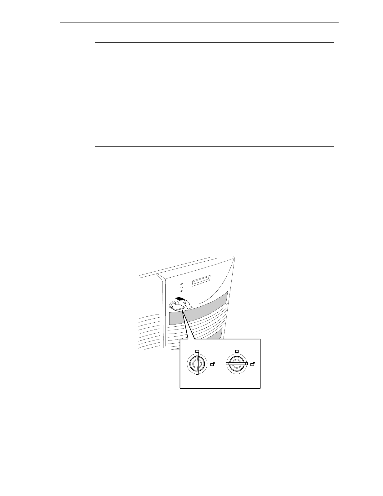
Table 1-4. System Status Abnormal Conditions
LED (Amber) Conditions
System Status Chassis intrusion (front cover)
Opening the Front Doors
You must open the right front door to turn the server power on or off, reset the
server, mount or dismount a floppy disk, or mount or dismount a hard disk
drive. Open the left front door to mount or dismount 5 1/4-inch removable
media devices.
Open the front doo rs as follows.
Unit fan alarm
Memory multi-bit error (SERR)
P6 bus error (SERR)
Thermal sensor
Temperatur e
Voltage
CPU thermal trip
PCI PERR# (OPB/ESC detect)
PCI SERR#
CPU internal error
WDT
IOCHK
To open the front doors, you need to use the securit y key provided with the
1.
server. Insert the secur it y key into t he key slot and turn the key to the right
(see the following figure).
LOCK
UNLOCK
System Overview 1-7
Page 24
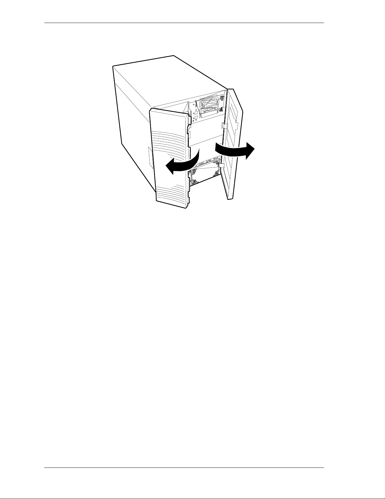
2. First open the right front door, then open the left door (see the following
figure).
1-8 System Overview
Page 25
Chassis Fea tures and Con tr ol s
Figure 1-2 shows the server fro nt chassis features and controls. Figure 1-3
shows the server rear chassis features and co nt rols.
E
J
K
H
F
G
I
D
CB
A
A
SCSI hard drive cages Used to mount the hard disks. Each cage contains four disks with
their three status LEDs mounted above.
B
Ejector button, 3 1/2-inch
diskette drive
Press to eject diskette.
C
Activity light, 3 1/2-inch
diskette drive
D
LCD panel Displays information about BIOS and system failures (error and
E
Power LED When green, power i s present in syst em . When off, power is
F
Status LED When green the system is O K. See Ta ble 1 - 2 for a l ist and
G
Disk LED When green, internal disk drives are being accessed. See Table
H
DC power switch Press to turn system DC power on or off.
I
Reset switch Press to cause a hard reset to the system; the power-on self test
J
Load/eject button, CD-ROM
drive
K
Activity light, CD-ROM drive When lit, drive is in use.
When lit, dri ve is i n use.
diagnostic information).
turned of f or power s ourc e is disrupt ed. See Table 1-2 f or a li st
and description of the system LED indicators.
description of the system LED indicators.
1-2 for a list and description of the system LED indicators.
(POST) will run.
Press to load CD and eject CD.
Figure 1-2. Front Chassis Features and Controls (front doors opened)
System Overview 1-9
Page 26
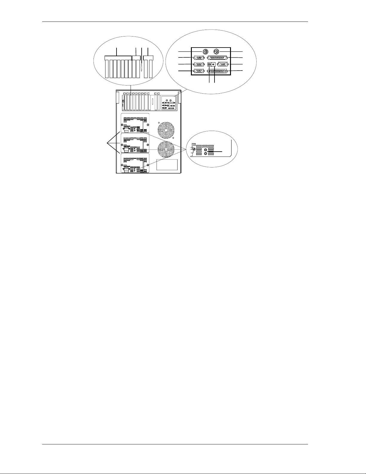
LONM
G
H
I
J
P
A Keyboard PS/2-c om p ati bl e 6- pi n mi ni- D I N c onnector.
B Printer LPT1 25-pin parallel port connector.
C VGA VGA mon it or 15-pin conn ec tor.
A
B
C
D
EF
K
D External-SCSI Narrow-SCSI 50-pin connector
See
E Dump button
F Function select
switches
G Mouse PS/2-compatible 6-pi n mini-DIN connect or.
H COM1 COM1 serial port 9-pin connector.
I COM2 COM2 serial port 9-pin connector.
J — Reserved.
K Power sta tus
LEDs
L PCI slots Two PCI add-in board slot locations (PCI #11 and PCI #12).
M Knocko ut Available to route SCSI signals to peripheral boxes.
N ISA slots Two ISA add-in board slot locations (ISA #1 and ISA #2).
O PCI slots Seven PCI add-in board slot locations (PCI #21, PCI #22, PCI #23, PCI #31, PCI #32, PCI
P Power supplies
(three shown)
Configuring Switch and Jumper Settings
See
Configuring Switch and Jumper Settings
Both indicators are gr een during normal op eration. Either or both indic ators go off when
power supply fails. See Table 1-1 for status descriptions.
#33, and PCI #34).
Possible configurations, installed from bottom most bay:
2 supp lies (nonredundant ), 3 supplies (one redundant).
Each power supply has a separate AC input power connector .
in Chapter 4 of this User’s Guide.
in Chapter 4 of this User’s Guide.
Figure 1-3. Rear Chassis Features and Controls
1-10 System Overview
Page 27
System Board Features
The board set includes the system I/O board, CPU base board, and a memory
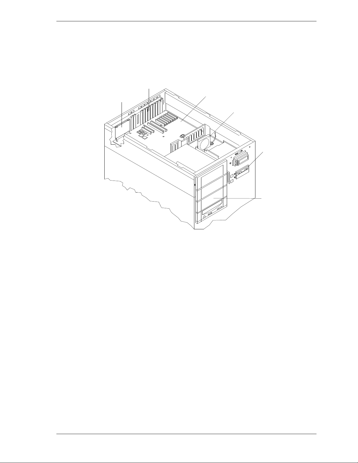
board. The system I/O board is mou nted at the top of the system. Figure 1-4
shows the system with the top co ver removed.
F
E
A
System I/O Board
B
Option board Fan
C
Diskette drive
A
B
C
D
D
Four 5 1/4-inch half-height bays with a CD-ROM
drive installed in bottom bay
E
I/O ris er boa rd
F
Expansion slot covers
Figure 1-4. System I/O Board Location
System Overview 1-11
Page 28
The CPU base board plugs into the underside of the system I/O board and the
memory board plugs into the CPU base board. Figure 1-5 shows the system with
the left side cover removed.
A
B
C
D
E
H
F
G
A CPU base board
B Memory b oa rd
C Rear CPU fan
Figure 1-5. CPU Base Board and CPU Board Location
1-12 System Overview
D Rear CPU fan
E Voltage Regulator Module socket
(VRM1 - VRM6)
F Front CPU fan (2)
G Pentium II Xeon processors (1 - 4)
H Voltage Module Socket (memory)
Page 29

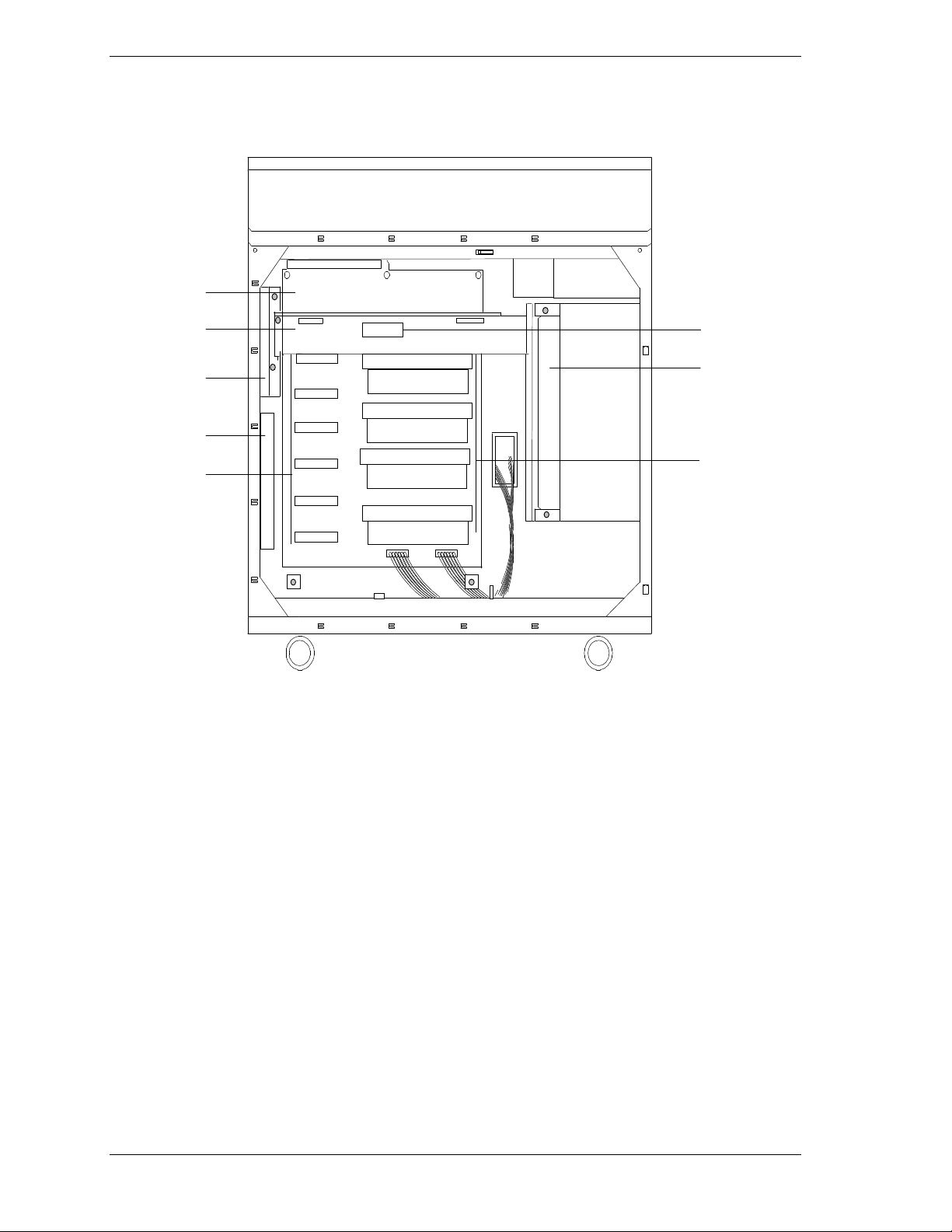
Figures 1-6, 1-7, and 1-8 show the major components on the system I/O board,
CPU base board, and Memory board. Table 1-5 summarizes t he featur es of the
boa rd set.
Table 1-5. Features of the Board Set
Feature Description
Multiple processor
slots
Upgradable
memory
Add-in board
support
SCSI controller Dual onboard SCSI-2 controller (PCI-based).
BIOS Flash memory-based BIOS (Basic Input/Output System ) and Setup
Video Integrated super VGA controller ships with either 1 MB or 2 MB of video
External device
connectors
Clock Real-time clock/calendar (RTC).
System hardware
monitoring
Configuration
utilities
Four processor sockets on the CPU base board, for a total of four
processors.
Sixteen DIMM sockets on the memory board, supporting up to 4 GB
memory us ing 256 MB DIMMs.
Two dedicated ISA bus slots and nine dedicated 32-bit PCI slots on the
system I/O board.
utilities.
memory. Upgrade socket (1 MB) is available for 1 MB system to
increase total video memory size to 2 MB.
Onboard connectors for two serial ports, parallel port, narrow SCSI port,
PS/2-compatible keyboard and mouse, and VGA monitor.
Detects chassis intrusion and contains sensors for temperature,
voltage, and fan failure.
Resource Config u ration Utility (RCU) and SCSISelect Utility.
System Overview 1-13
Page 30
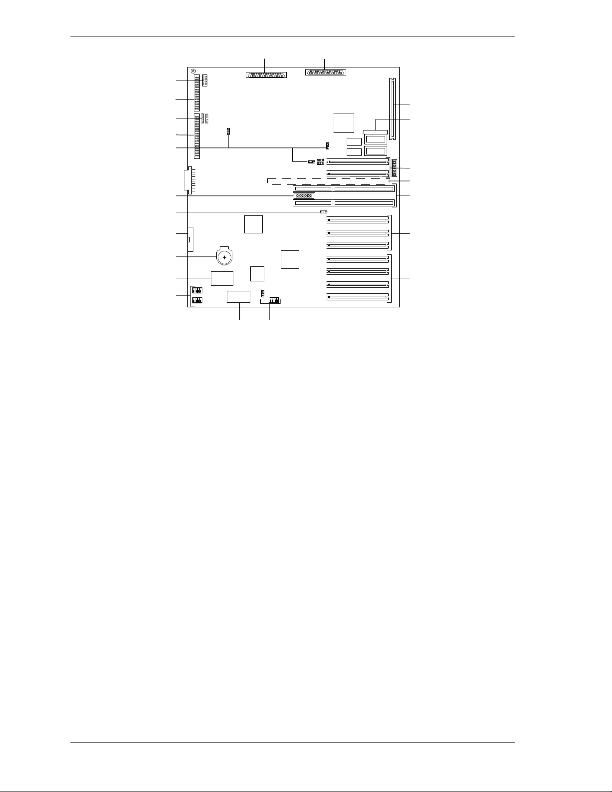
HI
J
SM
T
K
L
M
N
O
P
Q
R
M
G
F
E
D
C
B
A
A
PCI expansion slots (#31, #32, #33, and #34)
B
PCI expansion slots (#21, #22, and #23)
C
ISA expansion slots (#1 and #2)
D
CPU base board connector (underside of board)
E
PCI expansion slots (#11 and #12)
F
Optional Video DRAM sockets
G
I/O riser board connector
H
SCSI channel B connector
I
SCSI channel A connector
J
SCSI status cable connector
K
Option board fan connector
L
Front panel connector
M
Configuration jumpers
N
Reserved
O
Reserved
P
Diskette connector
Q
Real time clock battery
R
Flash board
S
Non-v olati le memo ry
T
Figure 1-6. System I/O Board Connector and Component Locations
1-14 System Overview
Power st atus c able c onnector
Page 31

F
A
I
B
G
H
C
D
E
A CPU front fan connector
B Memo r y board connector
C Pentium II Xeon processor (1 - 4)
D CPU front fan connector
E Configuration switch
F CPU rear fan connector
G Voltage module socket (VRM1 - VRM6)
H CPU rear fan connector
I Voltage Module Socket (memory)
Figure 1-7. CPU Base Board Component Locations
C
A DI MM sockets
B Configuration jumper
C DI MM sockets
Figure 1-8. Memory Board Component Locations
System Overview 1-15
A
B
Page 32

Processor
Each Pentium II Xeo n processor is packaged in a single edge contact (S.E.C.)
cartridge. The cartridge includes the processor core with an integrated 16 KB
primary (L1) cache; the secondar y (L2) cache; a thermal plate; and a back cover.
The cartridge is secured by a retention module attached to t he baseboard.
Depending on configuration, your system has one to four processors (see
Figure 1-7). Additional Pentium processors enhance performance and enable
symmetric multiprocessing (SMP). All processors access the same me mory and
I/O space and tasks can run on either CPU if your op er ating system (OS)
supports SMP.
Memory
The Memory board contains sixteen 168-pin DIMM sockets (see Figure 1-8,
A and C). A minimum system configuration includes 128 MB (using four 32
MB DIMMs) o f syst em memory. Sixteen DIMM sockets allow for system
memory expansion up to 4 GB (using sixteen 256 MB DIMMs). ECC
generation/checking is provided for detection and correction of memory errors.
Note:
Only use DIMMs approved for use in this server
system. Call your custom er service representative f or
information.
Bus Master I/O Expansion Slots
The server's expansio n capab il it ies meet t he needs o f high performance I/O
servers by providing a combination of PCI local bus and ISA connectors. The
system I/O board offers nine dedicated PCI slots and two dedicated ISA slots.
The system I/O board contains two ISA bus master I/O (input/output) expansion
slots (see Figure 1-6, C). The ISA architectur e suppo rt s 32-bit memory
addressing and 16-bit data transfers for the CPU, DMA, and bus masters.
The system I/O board also contains nine PCI bus master I / O expansion slots
(Figure 1-6, A, B, and E).
Real-Time Clock/Calendar
The real-time clock provides syste m clock/calendar information stored in a nonvolatile memory (NVRAM). The real-time clock battery (see Figure 1-6, Q)
provides power backup for the real-time clock.
BIOS
A BIOS and Setup Utility are located in the Flash memory (see Figure 1-6, R)
on the system I/O board and include support for system setup and PCI/ISA
Plug-and-Play auto-configurat ion. A number of security, reliability, and
management features ar e also incor porated to meet vital server needs.
1-16 System Overview
Page 33

Video
The onboard super VGA controller (PCI ) is a high-perfor mance SVGA
subsystem that supports:
BIOS compatibility with VGA, EGA, CGA, Hercules Graphics, and
MDA
1 MB of Video Memory expandable to 2 MB (Figure 1-6, F)
16-bit bus for high-speed displa y memor y access
hardware accelerated bit block transfers ( BITBLT)
72Hz refresh, non-interlaced at: 640x480, 800x600, or 1280x1024
resolutions
up to 16M colors at 640x480 and 800x600 resolutions, 64K colors at
1024x768 resolutions and 256 colors at 1280x1024 resolutions with the
optional 2 MB video memory.
SVGA drivers may be required to use the hi gh-
Note:
performance video modes.
SCSI Controller
The system I/O board includes a dual Ultra2 w ide SCSI-2 controller (Adaptec
AIC-7895) integrated as a PCI bus master. This controller supports data paths of
8-bit (fast/narrow SCSI) at a data transfer rate of 10 MB/sec and 16-bit
(fast/wide or ultra /wide SCSI) at a data transfer rat e of 20 MB/sec or 40
MB/sec. As a PCI bus master, this controller supports burst data transfer rates
up to the maximum of 133 MB/sec.
On this server, channel B is cabled to the four SCSI devices in the removable
media dr ive bays . Channe l A is available for optio nal SCS I dev ices.
Peripher al C o ntroller
The advanced integrated peripheral contro ller support s two serial ports and one
parallel port through the I/O riser board (see Figure 1-6, G). The advanced
integrated peripheral controller also supports the connection of two diskette
drives (see Figure 1-6, P).
External Device Connectors
The I/O panel provides connector s for a PS/2 compatible mouse and a keyboard,
connectors for VGA monitor, two serial port connectors, and a parallel port
connector. It also provides a narrow SCSI external connector .
®
Keybo ar d an d Mo us e
The keyboard/mouse cont ro ller is PS/2-co mpat ible.
System Overview 1-17
Page 34

Fans
In addition to the power supply fans, the system has an option board fan (see
Figure 1-4, B) cabled to the I/O board (see Figure 1-6, K) and three CPU fans
(see Figure 1-5, C, D and F) cabled to the CPU base board (see Figure 1-7, A,
D, F and H). The three CPU fans (front and rear) are redundant in configuration.
If one fan fails, its associated fan changes its rotating speed to high.
Peripheral Devices
The following paragraphs describe the Ultra2 wide SCSI-2 hard drive bays and
5 1/4-inch removable media drive bays.
Ultra2 Wide SCSI-2 Hard Drive Bays
The right side of the system contains up to three Ultra2 wide SCSI hard drive
cages for 3 1/2-inch SCSI-2 hard drives (see Figure 1-9). Each hard drive cage
has a hot-swap backplane that supports four drives. The backplanes require an
80-pin single connector att achment (S CA) co nnector o n the drives you install.
A drive carrier is required as part of the hot swap implementation. A 3 1/2-inch
peripheral between 1.0 and 1.6 inches high can be accommodated in each
carrier. A drive is mounted in the carr ier with four fasteners, and the carrier is
retained in the chassis by a locking handle.
A fault light on the front panel board g ives a genera l indication that there has
been a fault on a hot-swap drive. Each drive has a set of three lights to indicate
the fault or other status: power-o n (green LED), activity (green LED), or fault
(yellow LED).
Three hard drive cages
(EMI panel and exterior door
shown open)
Figure 1-9. Ultra2 Wide SCSI-2 Hard Drive Bays
1-18 System Overview
Page 35

The backplane has two main functions: SCSI drive control and system dat a
logging. Drive status is monitored to detect failing drives and to control LED
indicator s. T he backplane features include the following:
insertion and removal of hard drives while power is on (referred to as
“hot swap”)
simplified cable management
SCA connectors to simplify inserting and removing hard drives
SCSI management of fault LEDs.
Each backplane supports SCSI drives with SCA connectors.
Removable Media Drive Bays
On the upper left side of the system, four 5 1/4-inch half-height bays (see
Figure 1-10) are designed for peripherals with removable media (diskette, CDROM, tape). Two available adjacent 5 1/4-inch bays can be converted to a
single full-height bay. The 5 1/4- inch drives can be removed directly from the
front of the chassis. Remova l o f the syst em top cover may be required to
install/remove the device cables. Cosmet ic filler panel are inst alled over all
unused 5 1/4-inch bays.
Factory-installed CD-ROM reader plus
three bays for removable media
drives.
Factory-installed 3 1/2-inch diskette
drive plus second bay for removable
3 1/2-inch drive.
(Exterior doors shown open)
Figure 1-10. Removable Media Drive Bays
On the upper right side of the system, below t he LCD panel, are two built-in
3 1/2-inch bays. One contains a 3 1/2-inch diskett e drive that supports both 720
KB and 1.44 MB media (see Figure 1-10).
The SCSI terminati on r esi stor s must be installed in
Note:
the last SCSI drive of the dai sy chain cabling (bottom media
bay). All other dev ic es must have terminators removed.
System Overview 1-19
Page 36

System Power
The system may be configured with up to three 420 Watt power supplies. Each
supply automatically switche s between these input voltage ranges:
100-120 VAC at 50/60 Hz; 7 A maximum current
200-240 VAC at 50/60 Hz; 3.5 A maximum current
Each power supply provides DC outputs of +5 V, +12 V, +3.3 V, -5 V, and
-12 V. All output grounds connect to the power supply chassis and to earth
ground through the AC line cord. Each supply has:
individual AC input line cord that plugs into the external side of the
power supply
isolating device on each DC output so that the failure of one supply does
not affect the operation of the others
cooling fan integra l with each power supply enclosure. The fan circuit
implements fan failure detection.
In a system, power is drawn equally from all supplies installed. A system with
two power supplies can be fully loaded (all drive bays and add-in board slots
filled). The supp lies use a forced cur r ent - shar ing technique t hat ensures the
supplies share within 10 percent at full load. In a high-access system with three
power supplies, the third supply gives redunda ncy, becau se the load is
redistributed if one supply fails.
Software Locks via the BIOS Setup
The BIOS Setup has software feat ur es t hat let you cont rol access to one or more
parts o f the s ystem:
set and enable an administrative password
set and enable a user password
enable password on boot
disable writing to the diskette drive when secure mode is set.
If only a supervisor password is set and enabled, enter this password to boot the
server and run the SCU.
If both the user and administrative passwords are set and enabled, enter either
one to boot the server. Enter t he ad ministrative password to access t he SCU or
BIOS Setup to change the system configuration.
1-20 System Overview
Page 37

Setting Up Your System
Selecting a Site
Unpacking the System
Moving the System to the Site
Getting Familiar With the System
Making Connections
Connecting the Power Cords
Powering On Your System
2
Page 38

Selecting a Site
The system operates r eliably in a t ypical o ffice en vironme nt . Choo se a site that
meets the following requirements.
Site the system near grounded, three-pronged power o utlets.
Note:
NEMA 5-15R outlets for 100-120 Vac or NEMA 6-15R
outlets for 200-240 Vac. For other international sites, this
means three-pronged power outlets applicable for the
electrical c ode of t he r egion.
Be sure the power service connec tion is through a properly
grounded outlet.
For the United States and Canada, this means
!
CAUTION
Each power cord can be plugged into a separate phase of a main AC
supply, assuming the circuit is rated for that load.
Note:
For Denmark, the system must be c onnec ted to an
AC power source rated at 16 amps.
Select a site that is clean, dust-free, and well vent ilated. Keep front and
rear ventilating op enings free o f obstr u ctions. Locate the system away
from sources of heat, vibration, or physical shock
I solate the system from stro ng e lectr omagnetic fields and electrical noise
produced by electrical devices (such as air cond it ioners, large fans, large
electric motors, radio and TV transmitters, and high-frequency security
devices)
T he site shou ld be spacious enough to pro vide at least five inches (13
centimeters) behind the system and three inches (eight centimeters) on
each side of the system for proper cooling, airflow, and cable clearance.
Allow at least 11 inches (27 centimeter s) in front of the system for proper
front door clearance.
P osition the syste m for easy access for system maintenance and
installation of system upgrades.
2-2 Setting Up Your System
Page 39

Unpacking the System
!
CAUTION
Your system weighs approximately 207 pounds (94 kg). To
avoid personal i njur y , mak e sure you hav e someone help
you lift or move the system.
When you receive your system, inspect the shipping co ntainers prior to
unpacking. If the shipping boxes are damaged, note the damage, and if possible,
photograph it for reference. After re moving the cont ent s of the containers, keep
the cartons and the packing materials. If the cont ent s appear damaged when you
unpack the boxes, file a damage claim with the carrier immediately. To unpack
your system, see the unpacking instr uctions on the shipping carton.
Moving the System to the Site
Once you have selected t he system installation site, move it as follows.
1.
Casters are pro v ided on the botto m of the server. S low ly push the server t o
the selected installation locat ion.
!
CAUTION
For safety reasons, be sure to attach the caster holders on
the casters when the system is at the selected site.
2.
To stabilize the syst em, attach the caster holders o n t he cast er s as sho wn
below.
Setting Up Your System 2 -3
Page 40

Getting Familiar With the System
Before sett ing up your system, see Chapter 1, “System Overview,” to become
familiar with syst em features, such as the location of your system's securit y
keylocks and front and rear panel switc hes, indicators and connectors, etc.
Making Connections
Connect your keyboard, monitor, and mouse (see Figure 2-1). Connect any
external peripheral devices such as a printer or modem by following the
instruct ions included with t hese devices. To connect external SCSI cables, refer
to Cabling in Appendix A.
Note:
cable is inserted or rem ov ed when power i s appl ied to the
system.
Inserting a telephone line connector into a LAN board RJ- 45
port may result in personal injury and equipment damage.
Damage to the system may result if the keyboar d
!
CAUTION
2-4 Setting Up Your System
Page 41

IIKJ
E
F
G
H
A
B
C
D
A. Keyboard, PS/2-compatible 6-pin connector
B. Printer, parallel port 25-pin connector
C. VGA monit or, 15-pi n connector
D. External-narrow SCSI, 50-pin high density connector
E. Mouse, PS/2-compatibl e 6-pin conn ector
F. COM1, serial port 9-pin connector
G. COM2, serial port 9-pin connector
H. Res erved, 9-p in co nnect or
I. PCI slots, nine PCI add-in board slots
J. Reserved, connector knockout
K. ISA slots, two ISA add-in board slots
Figure 2-1. Making Connections
Setting Up Your System 2 -5
Page 42

Connecting the Power Cords
Plug the female end of each AC power cord into the input receptacles on the
rear of the power supplies (see Figure 2-2). Plug the male end of each power
cord into NEMA 5-15R outlet for 100-120 Vac or NEMA 6-15R outlet for 200240 Vac. If the power cords supplied with the system are not compatible with
the AC wall outlet in your region, o bt ain a suitable power cor d that meets t he
following cr iter ia.
The power cord must be rated for the available AC voltage and have a
current rating that is at least 125% of the current rat ing of the system.
T he power cord connecto r t hat plugs into the wall outlet must be
terminated in a grounding-type male plug designed for use in your region.
It must have certification marks showing certification by an agency
acceptable in your region.
T he po wer cord connector that plugs into the system must be an IEC-
type CEE-22 female connector.
The power cord must be less than 1.8 meters (6.0 feet) long.
!
WARNING
Your system shipped with two AC power cords. Do not
attempt to modif y or use the supplied AC power cords if it
not the exact type requi r ed.
Figure 2-2. Connecting the AC Power Cord
2-6 Setting Up Your System
Page 43

Powering On Your System
Power o n you r system as follows.
1. Make sure all external devices, such as a video display, keyboard, and
mouse (optional) have been connected, and t he power cor ds are connected.
2. Power on the video d isplay and any other external devices.
3. Open the right front door and press the power on/off switch on the front
panel (see Figure 2-3).
4. Verify that the Power LED is lit. If it is not lit, ensure the AC power cords
are connected to functional AC power sour ces.
After a few seconds your s yst em begins the internal Power-O n Se lf Tests
(POST). POST automatically checks the system, CPU module, memory,
keyboard, and most installed peripheral devices. If you have problems powering
on your system, refer to Problem Solving in Chap ter 6.
After you have successful l y powered on your system, verify that the system
boo ts to a DOS p r ompt . You can now run the E
XPRESSBUILDER
CD-ROM.
Power LED
Power On/Off Switch
Figure 2-3. Powering On Your System
Setting Up Your System 2 -7
Page 44

Page 45

Configuring Your System
Configuring Your System
Resource Configurat i on Utility (RCU)
BIOS Setup Utility
SCSISelect Utility
Viewing the Event Log
Configuring the RAID Controller
Configuring Syst em Jumpers and Switches
3
Page 46

Configuring Your System
Configuration and setup utilit ies are used to change your system configuration.
You can configure your system, as well as any option boards you may add to
your system, using the Resource Configuration Utility (RCU) diskette. Also,
several unique system parameters are configured using BIOS Setup (stored in
the system FLASH memory). A diskette is not needed to run BIOS Setup.
The SCSISelect Utility, also stored in the system FLASH memor y, is used if
you need to configure the SCSI controller in your system or to perform a SCSI
disk format or verify disk operation of these dr ives. A diskette is not needed to
run SCSISelect.
A Ut ilities d iskette contains the Event Log Utility. The Event Lo g Utility is used
to read stored syste m event information.
If your system has been factory configured, the RCU, BIOS Setup, or
SCSISelect utilities do not need to be run unless you want to change the
password or security features, add option boards or devices, or upgrade the
boards in your system.
There are some system configuration parameters that ar e set by jumpers.
However, these parameter s do not usua lly require change. F inally, the EZ-SCSI
utility is included with your s yste m. This program performs MS-DOS driver
installation for SCSI devices in your system a nd also inst alls ba sic utilities that
format a nd ma na ge SCSI hard disk drives . Refe r to the documentation supp lied
with the EZ-SCSI utility for more information.
The following provide procedures for running the RCU, BIOS Setup, and the
Utilities diskette. Also, a section describing t he syst em jumper configurations is
presented. Several configurat ion tables are a lso pro v ided to recor d changes you
make to the default system configuration.
You use the E
diskett e s.
XPRESSBUILDER
CD-ROM to create the RCU and Utilities
Resource Configuration Utility (RCU)
The Resource Configuration Utility is used to configure your system. The RCU
can be used to configure the memory subsystem, peripheral device subsystems,
and interface adapters. RCU recognizes ISA Plug-and-Play boards and PCI
boards and displays their configuration. ISA (non-Plug and Play) adapter boards
must be added to the RCU configuration to reserve the resources required by the
ISA boards.
After you add options using the RCU, the system automatically configures and
initializes them during system initialization at boot up.
3-2 Configuring Your System
Page 47

The RCU stores t he configuration information in the non-volat ile memory on
your system. When you exit the RCU, the configurat ion information is written
to non-volatile memory. The R C U also mainta ins the Set up co nfigura tio n,
which is stored in the batter y-backed me mory. This means that when you exit
the RCU, the Setup and RCU configurat ion agree with each ot her.
Using the RCU
If you are adding a non-Plug and Play ISA option board, run the RCU before
installing the board using procedures found in the Upgrades and Options
chapter of this guide. If you are upgrading system memory, do so before running
the RCU using procedures found in the Upgrades and Options chapter of this
guide. Use the RCU as fo llows.
Note:
configurati on. Always save the current settings before
reconfiguring the system.
The system can fail following improper
1. Power on the system.
2. If the diskette drive is disabled, enable it using the BIOS Setu p utility,
explained later (see BIOS Setup Utility). Specify the correct t ype of diskette
drive.
3. Using the E
XPRESSBUILDER
CD-ROM, create the RCU diskette. Note that the
CD-ROM refers to the RCU as the SCU.
4. Start the RCU by rebooting the system, with the RCU diskette in Drive A.
When the RCU banner is displayed, pr ess
and the Resource
Enter
Configuration Utility Main Menu shown in Table 3-1 displays.
5. Select Learn about configuring your computer from the RCU Main Menu
and press
through the information and press t he
6. Using the up and
. The Resource Configuration Utility Menu shown in Table 3-2
Enter
if you need information on system configuration. Read
Enter
key when you are done.
F10
down
arrows, highlight Configure Computer and press
displays. The keys that ar e active while viewing a screen are displayed on
the bottom of the screen.
Note:
additional information on each option. To retur n from help,
press
Press the F1 key at any time for help and
.
ESC
7. Select Step 1: Important System Configurat ion information and press
to learn more about the Resour ce Configurat ion Utility.
Configuring Your System 3-3
Enter
Page 48

8. Select Step 2 to add an ISA board to your system (see “ISA Board
Configuration”).
9. Select Step 3 to view your systems configurat ion settings. The normal
(default) RCU sett ings are sho wn in table 3-3.
Table 3-1. Resource Configuration Utility Main Menu
Menu Options Description
1. Learn about configuring your computer Provides basic instructions on system configuration and
using th e Help program.
2. Configure computer Lists automatically detected boards, and enables manually
adding, moving and removing boards. Plug-and-Play boards
don’t require configuration files. If the ISA board requires
configuration files, use “Add or remove boards” for a menu
to enter or change ISA board configurations. (See ISA
Board Configuration.)
INSERT adds a board not detected or has not been
installed.
DEL removes a selected board.
F7 moves a selected board to a different slot.
3. Set date Enables viewing and changing the date that the computer
uses.
4. Set time Enables viewing and changing the time that the computer
uses.
5. Maintain system configuration diskette Enables viewing and changing Configuration (.CFG) files
and System Configuration Infor ma tion (SCI ) files.
6. Exit from this utility Exits from the RCU.
Table 3-2. Resource Configuration Utility Menu
Menu Options Description
Step 1. Important System configuration
information.
Step 2. Add and remove boards Lists automatically detected boards, and enables manually
Step 3. View and Edit Details Enables viewing and changing your system configuration
Step 4. Examine Switches or Print Report Enables viewing the required switch and jumper settings
Step 5. Save and Exit Allows you to save your configuration and exits to the
Provides information on the Resource Configuration
program and how it differs from ISA board configuration.
adding, moving and removing boards. Plug-and-Play boards
don’t require configuration files. This list shows all the
boards and options that will be installed in your system.
settings including embedded features, functionality, IRQs,
and port selections. Perform Step 3 only if you need to
change the system default settings.
and allows printing of a configuration report.
operating system. You can also exit without saving.
3-4 Configuring Your System
Page 49

RCU Command Line Parameters
There are RCU options that can be enabled by star ting the RCU from the
command line with the appropr iate sw itch listed below. To enable an option,
insert the RCU diskette in drive A and type
followed by one of these command line parameters:
/HHigh resolution display. Sets the display mode to 43 lines for an EGA
add-in video controller board or to 50 lines for a VGA board. T he default is
25 lines for all add-in video controller boards.
/M Mono chr ome display. The d isplay screens are s ho w n us ing
monochro me attr ibutes, even o n a co lor display. The de fault is to display
color, unless a monochro me video display is detected. Use this parameter
when you have redirected the conso le to one of the onboard ser ial ports.
RCU Configuration Settings
Table 3-3 sho ws the recommended RCU settings for a sample system and
provides a place for you to record any changes you make to the settings. To
display the configuration settings, select St ep 3 under the Resour ce
Configuration Utility Menu. To edit any of the configurat ion parameters, use the
up and down arrows to highlight the desired configuration parameter and press
. Press ing F6 at this point allows you to edit any of the parameters
Enter
resources (IRQs, DMAs, I/O ports or memory).
at the MS-DOS prompt,
A:SD
Table 3-3. RCU Configurations
Main Menu Normal Setting Your Configuration
System - Express 5800 HX4500 System Board
RS - 232 COM Port 1 PORT 3F8h - 3FFh IRQ 4
RS - 232 COM Port 2 PORT 2F8h - 2FFh IRQ 3
Parallel Port PORT 378h - 37Fh IRQ 7
Floppy Controller Enabled
Mouse Controller Enabled
PCI -2 - PCI Ether net Contr oller
PCI Function 1 Enabled
PCI -3 - PCI Ether net Contr oller
PCI Function 1 Enabled
Embedded - PCI PCI Bridge - Bus 2
PCI Function 1 Enabled
Embedded - PCI SCSI Controller
PCI Function 1
PCI Function 2
Embedded - PCI VGA Controller
PCI Function 1
Standard VGA Resources
Enabled
Enabled
Enabled
Enabled
Configuring Your System 3-5
Page 50

ISA Board Configuration
If adding a non-Plug and Play ISA board to your system, use the following
procedures to define and add the option board. It’s necessary to define an ISA
board to prevent other boards in the system from using the same IRQ levels,
DMA channels, I/O port addresses, or memory addresses, that your I S A board
uses.
You must run the RCU and add the ISA board to the configurat ion before
installing the ISA board in the system. Otherwise, the reso urces on the ISA
board may conflict with a Plug-and-Plug board in the system.
BIOS automatically assigns ISA P lug-and-P lug boards t o the next availa ble slot .
If the slot displayed in Step 2: “Add or Remove Boards” is not the actual slot, it
can be moved by using the F7 function key.
IRQ levels, DMA channels, I/O port addr esses,
Note:
and memory addresses defined using this procedure should
reflect the same setti ngs defined by supplied jumpers and/or
configurati on doc um ents.
1.
Insert the RCU diskett e into dr ive A: and power o n t he system. The syst em
boots-up using the RCU diskette.
2.
The RCU Main Menu shown in Table 3-1 is displayed. At the Startup Menu,
enter choice 2, Configure Computer.
3.
The Resource Configuration Utility Menu shown in Table 3-2 is displayed.
Select Step 2 Add or Remove Boards and press
4.
The Step 2: Add or remove boards screen is disp layed. At this scree n s elect
Add by pressing
5.
The Add screen is displayed telling you to locate t he diskette that contains
Insert
the .cfg file for the board. Press
6.
The Select a Configuration (CFG) file to add screen is displayed. At this
.
Enter
at this screen.
Enter
.
screen select No t L i st ed by pressing F5.
7.
The Add a board without a .cfg file screen is displayed. Read through the
information and press
. The Add a board without a .cfg file screen
Enter
reappears. When t he screen reappears select Create .cfg file and press
8.
The Create A Board CFG File screen is displayed. At this screen ente r t he
board description and manufacturer and press
9.
The New Board Setup scr een is displayed. Using t he s c rollable lis t se lect the
Enter
.
resources used by the new ISA board. Table 3-4 pro vides a place for you to
record the configuration you assign to the board.
Enter
.
10.
Press
when you are finished selecting the resources used by the new
F10
ISA board.
3-6 Configuring Your System
Page 51

11. The View Current Settings screen is d isplayed. Pr ess
Enter
to save the
current settings.
12. The Add confirmation screen is displayed. Review the manufacturer’ s
comments and press
Table 3-4. ISA Board Configurations
ISA Board Definitions Your Configuration
Board Description:
Manufacturer:
Interrupts (Select from scrollable list)
DMA Channels (Select fro m scrollable list )
Port address (Select from scrollable list)
Start
End
Mem ory addres s (Sel ect fr om scrollable l ist)
Start
Length
Enter
.
Slot (Select from scrollable list)
13. The Add screen is displayed. Select the slot in w hich you want to install the
board and press
Note:
configurati on, a Caution message is displayed. Pr ess
at the message. This l eads you t o screens that allow you to
resolve the conflic t.
If the board you add causes a conflict in the
Enter
.
Enter
14. The Step 2: Add or remove boards screen is displayed . At this screen se lect
Done by pressing
F10
.
15. The Steps in configuring your computer screen is displayed. At this screen
select “Step 4: Examine switches or print report” and press
Enter
.
16. The Step 4: Examine switches or print report screen is displayed. T he
boards marked with an arrow indicate that the boards in your system may
have jumpers and switc hes t hat you must physica lly verify or that a software
statement with additional information about the board is provided. Select
Done by pressing
F10
.
Note:
configurati on does not have switches, jumpers, software
statements, or connection information, an Information
message appears on the screen. Pres s
to the next step.
If the ISA board you are adding to the
Enter
and proceed
Configuring Your System 3-7
Page 52

17. The Steps in configuring your computer screen is displayed. At this screen
select “Step 5: Save and exit” and press
Enter
.
18. The Save and exit screen is displayed. At this screen se lect “Save the
configuration and restart t he co mputer” and press
Enter
.
19. The Reboot screen is displayed. At t h is screen press
20. Now that you have reserved the syst em resources, you can insta ll the ISA
board.
BIOS Setup Utility
The BIOS Setup Utility, like the RCU, is used to change system configuration
parameters. This utility has several unique parameters and many parameters that
are also configurable w ith the RCU. The utility is reside nt in the syst em FLASH
memory and does not require a diskette or an oper ating syste m present to run.
However, some parameters set with the BIOS Setup Utility that can also be set
with the RCU, are overwritten by the RCU the next time the RCU is run.
Using the BIOS Setup Utility
You access the BIOS S et up Utility when you tu r n o n or reboot your system. To
run the BIOS Setup Utility, perform the following pro cedur e.
1. Power on or reboot the system. BIOS displays the following:
Press <F2> to enter SETUP
Enter
.
2. Press F2. After BIOS POST completes, the BIOS Setup Utility starts and the
Main Menu is displayed. The menu bar at the top o f the Main Me nu lists t he
following selections.
Menu Use
Main Use this menu for basic system configuration.
Adv anced Use thi s men u f or settin g the Advanced Fea tures availabl e on your
system.
Security Use this menu to set User and Supervisor Passwords and the Backup
and Virus-Check reminders.
Server Use this menu for confi guring Server Features.
Exit Exits the current menu.
Use the arrow keys to select a menu or an ite m on a displayed menu. Press
the value keys (listed in the table below) to cycle through the allowable
values for the selected field. Use the Exit menu’s “Save Values” select ion to
save the c urrent values on a ll the menus.
To display a submenu, posit ion the curso r on a selection that has a submenu
and press
. Selections with submenus are preceded by an arrow.
Enter
3-8 Configuring Your System
Page 53

See the following table for information on the keys you use with Setup.
These keys are also listed at the bottom of the Setup menu.
Key Function in Setup Menu
F1 or Alt-H General Help window.
ESC Exit the curr ent m enu.
← or → arrow keys
↑ or ↓ arrow keys
TAB or SHIFT-TAB Cycle cursor up and down.
HOME or EN D Move cursor to top or bottom of wi ndow.
PAGE UP or PAGE DOWN Move cursor to next or previous page.
F5 o r - Select the previous val ue for the field.
F6 or + or SPACE Select the next value for the field.
F9 Load default configuration values for this menu.
F10 Load previous configuration values for this menu.
ENTER
ALT-R Refresh the s creen.
Select a different menu.
Move cur sor up and dow n. The cursor moves only to the
settings that you can change.
Exec ute c omma nd or Select
BIOS Setup Configuration Settings
Table 3-5 shows the normal settings for the BIOS Setup Utility and provides a
place for you to record any changes you make to these settings.
➨
submenu.
Exiting BIOS Setup
To exit Se tup, select Ex it from the me n u bar to dis pl ay th e Exit Setup me nu.
The following describes the options on this menu. Note that ESC does not exit
t his me n u. You must select one of the items from the menu or me nu bar to exit
this menu.
Selection Description
Save changes and Exit Stores the selections displayed in the menus in CMOS and exits
Exit without Saving
Changes
Get Default Values Displays default values for all Setup menus. Useful if BIOS
Load Previous Values Reverts to previously saved values if the new values have not
Save Changes Stores the current selections without exiting the Setup program.
the Setup program.
Exits the program without saving any changes you have made in
this session. Previous selections remain in effect.
detects a problem with the values stored in CMOS.
been saved to CMOS.
Configuring Your System 3-9
Page 54

Table 3-5. BIOS Setup Configurations, Main Menu
Menu Parameter Name Normal Setting or
Display Only
MAIN MENU
System Time
Enter current time (hour, minutes, seconds on
24 hour clock).
System Date
Enter current date.
*Diskette A:
Use +/- to change values; indicates the type of
diskette drive installed.
*Diskette B:
Use +/- to change values; indicates the type of
diskette dri ve ins tall ed (Not Inst alled in your
system).
Memory Cache
Press Enter for menu.
Memory Cache Enabled
Cac he Sys tem BIOS Area Write Protec ted
Cac he Video BIOS Area Write Protec ted
Cache Base 0 - 512K Write Back
Current Time
Current Date
1.44MB, 3 1/2”
Not Installe d
Your Configuration
Cache Base 512K - 640K Write Back
Cac he Extended Memory Ar ea Write Back
*Cache Memory Regions
Cache C800-CBFF Uncached
Cache CC00-CFFF Uncached
Cache D000-D3FF Uncached
Cache D400-D7FF Uncached
Cache D800-DBFF Uncached
Cache DC00-DFFF Uncached
Memory Shadow
Press Enter for menu.
System Shadow Enabled
Video Shadow Enabled
*Regions with Legacy Expansion ROMs
* This parameter is overwritten by the RCU setting.
3-10 Configuring Your System
Page 55

Table 3-5. BIOS Setup Configurations, Main and Advanced Menu
Menu Parameter Name Normal Setting or
Display Only
MAIN MENU
*Boot Sequence
Press Enter for menu.
POST Errors Enabled
Boot Sequence A: then C:
*Numlock
Press Enter for menu.
Numlock ON
Key Click Enabled
Key Board auto-repeat rate 10/sec
Key Board auto-repeat delay 1 sec
Base Memory: 640 KB Display only
Extende d Memory: 127 MB Display only
ADVANCED MENU
*Integrated Peripherals
Press Enter for menu.
Serial Port 1 3F8, IRQ 4
Serial Port 2 2F8, IRQ 3
Parallel Port 378, IRQ 7
Parallel Mode Bi-directional
Diskette Controller Enabled
Memory Reconfiguration
Press Enter for menu.
Memory Reconfiguration Enabled
DIMM Group #1 Status Normal
DIMM Group #2 Status none
DIMM Group #3 Status none
DIMM Group #4 Status none
Your Configuration
* This parameter is overwritten by the RCU setting.
Configuring Your System 3-11
Page 56

Table 3-5. BIOS Setup Configurations, Advanced Menu
Menu Parameter Name Normal Setting or
Display Only
ADVANCED MENU
Clear DIMM Errors Press Enter
DIMM Error Pause Enabled
CPU Reconfiguration
Press Enter for menu.
CPU Reconfiguration Enabled
CPU #4 Status Normal
CPU #3 Status Normal
CPU #2 Status Normal
CPU #1 Status Normal
Clear CPU Errors Press Enter
CPU Error Pause Enabled
PCI Devices
Press Enter for menu.
PCI Parity Error Enabled
PCI IRQ1 Auto
PCI IRQ2 Auto
PCI IRQ3 Auto
PCI IRQ4 Auto
PCI IRQ5 Auto
PCI IRQ6 Auto
PCI IRQ7 Auto
PCI IRQ8 Auto
PCI IRQ9 Auto
PCI IRQ10 Auto
PCI IRQ11 Auto
PCI IRQ12 Auto
PCI IRQ13 Auto
Your Configuration
3-12 Configuring Your System
Page 57

Table 3-5. BIOS Setup Configurations, Security and Hardware Menu
Menu Parameter Name Normal Setting or
Display Only
PCI IRQ14 Auto
PCI IRQ15 Auto
PCI IRQ16 Auto
Advanced
Press Enter for menu.
Reset Config uration Data No
SECURITY MENU
Supervisor Password is Disabled
User Password is Disabled
*Set Supervisor Password Press Enter.
Set User Password Press Enter.
**Password on boot Disabled
**Diskette Write Normal
**Diskette access Everyone
System backup reminder Disabled
Virus check reminder Disabled
Power Switch Mask Unmasked
SCSI Select Utility Mask Unmasked
Your Configuration
SYSTEM HARDWARE MENU
Thermal Sensor
Press ENTER for menu.
Thermal Sensor Enabled
Upper Limit 65
Lower Limit 5
ESM IRQ IRQ 10
Console Redirection Disabled
SMI Enabled
Error Log Initialization No
* Enabling supervisor password requires a password for entering SETUP.
** These parameters require prior setting of supervisor password.
Configuring Your System 3-13
Page 58

SCSISelect Utility
The system I/O board includes an integrat ed AIC7895 dual SCSI host controller
used to manage SCSI devices in your system. When used, Channel A of this
controller provides support for four internally mounted u ltra/w ide hard disk
drives. Channel B provides support for internally mounted tape and CD-ROM
devices as well as externally co nnect ed S CSI devices.
The integrated SCSI host controller is configured using the SCSISelect utility.
Use the SCSISelect utility to:
change the SCSI host adapter s default values.
check and/or change SCSI device settings for a particular device.
perform low-level formatting on SCSI disk devices.
perform verify operations on SCSI disk devices.
When disabling access t o t he SCSIS elect Ut ilit y, the SCSI S elect utility should
be use d in conjunction with the BIOS Setup Utility. Changing the BIOS Set up
Utility “SCSI Select Ut ility Mask” parameter to Masked prevents t he use of the
SCSI Select utility via Ctrl-A, but the “Press <Ctrl-A> for SCSI Select” prompt
is still displayed. Changing the SC SISelect utility “Displa y <Ctrl-A> M e ssage
During BIOS Initialization” parameter to Disabled prevents the prompt from
being displayed. In combination these parameters can be used to prevent access
to the SCSISelect utility during boot.
Using the SCSISelect Utility
To run the SCSISelect Utilit y, perform the following procedure.
1. Power-o n the system. The syst em boots u p.
2. Dur ing in it ializa tion, pr e ss
SCSISelect detects the AIC-7895 host adapter, it displays a selection menu
listing the bus and device number of each channel. When the selection menu
appears, select the channel you wish t o configure as follows.
Bus : Device : Channel Selected SCSI Channel
00 : 01 : A A
00 : 01 : B B
3. Once you select the channel, the following screen is displayed.
Screen Description
Configure/View Host Adapter Settings Configure host adapter and device settings.
SCSI Disk Utilities The utility scans the SCSI bus for SCSI devices,
+ A. The SCSISelect Utility start s. When
Ctrl
report s a description of each devic e. Run t hese
before
utiliti es
configuring SCSI devices.
3-14 Configuring Your System
Page 59

4. If you wish to format a disk, ver ify disk media, or display a list of devices
and their SCSI Ids, se lect “SCS I Disk Utilities”. If you wish to configure the
adapter or a device, select “Configure/View Host Adapter Settings”.
SCSISelect Conf iguration Settings
The following keys are active for all SCSISelect screens.
Key Action
Arrows
ENTER
ESC
F5
F6
Table 3-6 shows the normal settings for the SCSISelect Utility and provides a
place for you to record any changes you make to these settings.
Exiting SCSISelect
To exit SCSISelect, press
changed any settings, you are prompted to save t he changes befor e you exit).
Up and down arrows move from one parameter to another within a
screen.
Displays options for a configurable parameter. Selects an option.
Moves back to previous screen or parameter or EXIT if at the Main
menu.
Switches between color and monochrome.
Resets to host adapter defaults.
until a message prompts you to exit (if you
Esc
Configuring Your System 3-15
Page 60

Table 3-6. SCSISelect Setup Configurations
Recommended Setting or
Option
SCSI Bus Interface Definitions
Host Adapter SCSI ID 7
SCSI Parity Checking Enabl ed
Host Adapter SCSI Termination Enabled
Additional Options
Boot Device Options Press Enter for menu
Boot Channel A First
Boot SCSI ID 0
Boot LUN Number 0
SCSI Device Configuration Press Enter for menu
Initiate Sync Negotiation Yes
Maximum Sync Transfer Rate 40.0
Enable Disconnection Yes
Initiate Wide Negotiation Yes
Send Start Unit Command Yes
BIOS Multiple LUN Support no
Include in BIOS Scan Yes
Advanced Configuration Options Press Enter for menu.
Reset SCSI Bus at IC Initialization Enabled
Extended BIOS Translation for DOS Drives
>1 GByte
Host Adapter BIOS (Configuration Utility
Reserves BIOS Space)
Support Removable Disks
Under BIOS as Fixed Disks
1, 2
Display <Ctrl-A> Messages During BIOS
Initialization
BIOS Support for Bootable CD-ROM Disabled1
BIOS Support for INT 13 Extensions Enabled
1
No effect if BIOS is disabled.
2
Do not remove m edi a from a removab l e m edi a dr i ve if it is und er B IO S c ontr ol.
3
Set to Disable if NetWare 3.12 or 4.11 Network Operating System is installed.
4
Set to 40.0 for channel A or 10.0 for channel B.
5
Set to Yes for channel A or No for channel B.
6
Set to Enabled for channel B or Disabled for channel A.
7
Set to 0 for channel A or 5 for channel B.
Display Only Your Configuration
7
4
5
1 and 5
1
1
Enabled
Enabled.
Boot Only
Enabled
1
1
1
6
1
3-16 Configuring Your System
Page 61

Configuring the RAID Controller
The system comes with a three channel SecuRAID 530 Redundant Array of
Inexpensive Devices (RAID) Controller board. The board gives your system the
added security of fault tolerance. The system is pre-configured at the factory.
Use Table 3-8 to determine how the RAID controller was configured at t he
factory. If you want to change the RAID level or add additional hard disks to the
array, you must use the RAID Configuration Utility.
If you are adding the RAID controller to an existing system, the RAID
Configurat ion Utility allows you to configure your disk array before installing
your network operating system.
Table 3-8. RAID Configurations
Number of
Hard Drives
1JBOD1 JBOD (Mylex RAID 7) JBOD is an acronym for Just
21 2 Mirrorin g (RAID 1) Drives are paired and mirrored.
35 3 Striping with Parity (RAID 5) Data is striped across
4 or more 5 4 (one standby
RAID Level
Configured
Hard Drives in
Array
drive)
Description
a Bunch Of Disks. Each drive can operate
independently as with a common host bus adapter; or
multiple drives may be spanned and seen as a single
very large drive. No redundancy is provided.
All data is 100% duplicated on an equivalent drive
(fully redundant).
several physical driv es. Par i ty protect ion is used for
data redundancy.
Striping with Parity (RAID 5) with a standby drive
The a rray consi sts of three ON-LINE drives and on e
STAN DBY dr ive. The standby replacement drive, or
hot spare, is one of the most important fea tures RAID
provid es to ac hiev e automati c, non-stop service wi th a
high degree of fault-tolerance.
The RAID Config uration Utility utility is inc luded with the RAID co ntro ller.
The SecuRAID 530 controller supports various versions o f RAID technology
(referred to as RAID levels). To use any RAID level, you must configure the
RAID controller using the RAID Configuration Utility configuration utility
prior to installing your Network Operating System. For an explanation of this
utility, refer to the RAID Configuration Utility Utilities Installation Guide and
User Manual that was shipped with the controller. Chapter 2 of the manual
(Configuration Strategies) describes RAID technology and provides tips on
making your array perform well in your specif ic a pplicat ion. C ha pter 3
(Preparing the Array) covers array hardware preparation, configuration, and
initialization. After completing the steps in chapter 3, you can install your
Network Operating System.
Configuring Your System 3-17
Page 62

If you want to remotely configure the array (from a PC client); increase arr a y
capacity online; or monitor statistics on disk and controller act ivity, you must
install the Global Array Manager (GAM) option provided with your RAID
subsystem. The GAM option includes diskettes and user do cumentation. Use of
GAM is docu mented in the Global Array Manager 2 Server Installation Guide.
Increasing array capacity is covered in the MORE User Guide. This user guide
covers enhancements to both the Global Array manager and RAID
Configur atio n U til ity utilities softw are t ha t implement on line RAID expansion
(MORE) technology.
Configuring System Jumpers and Switches
This section describes t he jumpers and switches used on the I/O riser boar d,
CPU base boar d, and syst em I/O board.
Before You Begin
Only a qualified technical person should perform the procedures in this section.
Note:
system boards. Modify the boards only at an ESD
workstation. Otherwise, wear an antistatic wrist str ap
attached to chassis ground.
The system jumpers ena ble you to set specific operating parameters for your
system. A jumper is a small plastic-encased conducto r (shorting plug) that slips
over two jumper pins.
Electrostatic discharge (ESD) can damage the
Configuring I/O Riser Board Function Select Switches
The following describes how to configure and set the I/O riser board function
select sw itches for specific operating parameters. The function select DI P
switches configure t he use of the fro nt panel reset switch and the use of an
optional uninterruptible power supply (UPS) unit.
!
CAUTION
Before doing the procedur es i n this section, make sure that
your system is powered off. Unplug all AC power cords from
the back of the chassis. Failure to disconnect power befor e
setting switches and mov ing jumpers can result in personal
injury and equipm ent damage.
Figure 3-1 shows the DIP sw itches. The sw itc hes consist of a block of four
switches, access ib le o n t he I/O panel locat ed on the I/O r iser boar d at the rear of
the chassis.
3-18 Configuring Your System
Page 63

A
B
Function Select Switches and Dump
Button
4
ON
DIP
2143
A Function select switches
B Reserved
Figure 3-1. Function Select Switches
Note:
your system configur ation. If your system requires a switch
change, change only the switch setting for that condition.
Otherwise keep the switches at t heir factory settings.
The switches are set correctly at t he factory for
Table 3-9 shows the switch configurations and functions. Set the switches per
Table 3-9 and the following steps. To change a switch set ting, use the following
procedure.
Note:
switches, otherwise the settings will not be recognized.
At the front of the server, pr ess the Power switch off.
1.
At the rear of the server, locat e t he Funct ion Select DIP switch (see Figure
2.
Power must be completely off before setting the
3-1) that you want to change.
Set the appropriate switch on or off, accord ing to Table 3-9.
3.
Note:
UPS unit, power the unit up before switching power on the
server.
Press the main Po wer switch on.
4.
If using an UPS unit, the server powers up as soon as the UPS unit is
If you set SW3 to On for use with an optional
turned on.
If not using the UPS unit, press the Power button on the front of the
server.
Configuring Your System 3-19
Page 64

Table 3-9. Function Select Switch Settings
SwitchDescription Settings Function
SW1 Reserved for
future use.
SW2 Reset
Off (fact ory setting)
On
Off
Front panel Reset pushbutton switch is disabled.
pushbutton
control
SW3 AC power
source control
On (factory setting)
Front panel Reset pushbutton switch is enabled.
Off (fact ory setting)OnDC power can only be turned on from the front panel
switch. If AC goes off and then back on, system will not
power on until front panel switch is used.
DC power will turn on when AC power comes on. Use
this setting with an optional uninterruptible power
supply (UPS) that auto-cycles AC power or if no UPS
and auto-power on after power lose is desired.
SW4 Reserved for
future use.
Off (fact ory setting)
On
Configuring CPU Base Board Function Select Switches
This section describes how to configure the CPU base board function switch for
the speed of the CPUs. Figure 3-2 shows the location and settings of the CPU
base board sw itche s .
Figure 3-2. CPU Base Board Function Switch
3-20 Configuring Your System
CPU Speed
400 MHZ
450 MHZ
4
3
2
1
OFF
4
3
2
1
OFF
Page 65

Confi gur i ng Me m ory Bo ar d Function Jumper s
This section describes how to configure the memory board jumper for 60ns.
Figure 3-3 shows the location and set tings of the memory board jumper.
P02
P04
A
B
C
P14
P16
Figure 3-3. Memory Board Jumper
D
Configuring System I/O Board Switches and Jumpers
The system I/O board switc hes and jumpers e na ble you to set specific operating
parameters for your system. Figure 3-4 shows the location of the switches and
jumpers. Table 3-10 lists the syste m I/O board switches and jumpers a nd t heir
factory default settings.
P03
P05
P15
P17
60 50
Configuring Your System 3-21
Page 66

Reserved
10K9
A
B
C
Reserved
P16
SCSI Channel A
4J1
A
B
C
Reserved
P25
Reserved
13A1
2143
OFF
Figure 3-4. System I/O Board Switches and Jumpers
3-22 Configuring Your System
CMOS Clear
Password Clear
13A
2143
OFF
FLASH Code
9A2
A
B
C
Model Type
8A2
2143
OFF
Page 67

Table 3-10. System I/O Board Switch and Jumper Configurations
Switch/
Jumper Description Option Setting
SCSI Channel A
4J1
FLASH Code
9A2
Reserved
P16
Reserved
P18
Reserved
10K9
Reserved
13A1 SW1
Reserved
13A1 SW2
Reserved
13A1 SW3
SCSI channel A
select
FLASH
reprogramming
protection
All three jump ers
must be to the left.
All nine jumpers
must be in.
Narrow SCSI for channel
A
Wide SCSI for channel A
BIOS write protected; no
update
BIOS not write protected;
update
Required on factory
default.
Required on factory
default.
Required on factory
default.
Required on factory
default.
Required on factory
default.
Required on factory
default.
A-B
B-C
A-B
B-C
A-B
B-C
IN IN IN
B-C B-C
OFF OFF OFF
OFF OFF OFF
OFF OFF OFF
Factory
Default
B-C
(down)
B-C
(down)
B-C
(left)
(down)
Your
Setting
B-C
(left)
B-C
(down)
Reserved
13A1 SW4
CMOS Clear
13A SW1
Pas sword Clear
13A SW2
Reserved
13A SW3
Reserved
13A SW4
Model Type
8A2 SW1
Model Type
8A2 SW2
Model Type
8A2 SW3
Real-tim e clo ck
CMOS protection
Password
protection
Used with switches
8A2 SW2, 8A2
SW3 and 8A2 SW4
to set server model
Used with switches
8A2 SW1, 8A2
SW3 and 8A2 SW4
to set server model
Used with switches
8A2 SW1, 8A2
SW2 and 8A2 SW4
to set server model
Required on factory
default.
RTC CMOS clear
RTC CMOS not cleared
Pas swor d clear
Pas sword protected
Required on factory
default.
Required on factory
default.
Required on factory
default.
Required on factory
default.
Required on factory
default.
OFF OFF OFF
ON
OFF
ON
OFF
OFF OFF OFF
OFF OFF OFF
ON ON ON
ON ON ON
OFF OFF OFF
OFF
OFF
Model Type
8A2 SW4
Used with switches
8A2 SW1, 8A2
SW2 and 8A2 SW3
to set server model
Required on factory
default.
OFF OFF OFF
Configuring Your System 3-23
Page 68

Setting Swit ches and Jumpers
!
Before doing the procedur es i n this section, make sure that
your system is powered off. Unplug the AC power cords
from the back of the chassis. Failure to disconnect power
before moving the jumper s can resul t in personal injury and
equipment damage.
CAUTION
Note:
wrist strap.
Observe static precauti ons. Use an antistatic
Change the setting of any of the configurat ion switc hes or jumpers on any of the
syste m boards as follows.
1.
Power off the system and remove t he co vers as described in Chapter 5,
“Problem Solving.”
2.
Check to ensure the syste m power cords are removed from the back of the
system.
3.
Locate the switch or jumper you are changing (see Figure 3-4).
4.
To change a switch setting, use a pen or your finger to move the switc h to
the desired setting. To change a jumper setting, use a pair of needle-nose
pliers or your fingers to remove the jumper from its current location.
Position the jumper over the two pins for the desired setting and press it onto
the pins. Be careful not to bend the pins. See Table 3-10 for board switch or
jump e r settings.
5.
Record changes to the board sett ings in Table 3-10.
6.
Install the system covers and power up the system.
7.
Run the Setup Utility to verify your r econfiguration of the board.
3-24 Configuring Your System
Page 69

BIOS
The following contains procedures for updating your BIOS and changing the
language used by the BIOS Setup Utility.
Updating the BIOS
You should use this procedure when you receive a BIOS FLASH disket te from
your service representative. Update the system BIOS as follows.
Note:
you want to save the event log cont ents, run the Event Log
Reader Utility .
This procedure clears the ev ent log contents. If
1. Insert a bootable DOS diskette into Drive A and power up the system.
2. Remove the MS-DOS diskette and insert the BIOS FL ASH d iskette into
Drive A.
3. Enter PHLASH and press
Enter
.
4. After the system reboots, load the default values by pressing F2 to enter
setup. At the Exit Menu, select GET DEFAULT VALUES.
5. Clear the event log by selecting CLEAR EVENT LOG at the Server Menu.
Press space bar to change NO to YES and press
CHANGES & EXIT and press
Enter
to continue. The system reboots.
. Select SAVE
Esc
If the procedure fails, perform the following steps and then retry the Update
BIOS procedure.
1. Turn off the system and remove the panels as described in Chapter 4,
“Upgrading Your System.”
2. Ensure the FLASH Code jumper 9A2 is set to pins B-C to enable updates to
the BIOS (see Figure 3-4).
3. Replace the panel and power up the system with the BIOS FLASH diskett e
inserted in Drive A.
Configuring Your System 3-25
Page 70

Changing the BIOS Setup Language
The BIOS Setup Utility used by your system supports two languages: English
and one other. As shipped from the facto r y, the BIOS Setup Utility supports
English and French. If you want to use either German, Spanish, or Italian as the
second language, you must use the Multi-Language BIOS FLASH Diskettes to
change the supported languages. The diskettes include the following.
Multi-Language B IOS FLASH Diskette 1 of 2 . This diskette contai ns the
English/French and English/German language files along wit h t he
PhoenixPhlash Utilit y.
Multi-Language B IOS FLASH Diskette 2 of 2 . This diskette contai ns the
Eng lish/Spanish a nd Eng lish/Ita lian language files a long with the Cris is
Recovery Utility.
Language Change Instructions
Follow these steps to change the BIOS Setup language.
1. Using the E
XPRESSBUILDER
CD-ROM, create the Multi-Language BIOS
FLASH Diskettes.
2. Insert Multi-Language BIOS FLASH diskette 1 of 2 into floppy disk drive A
and power up the system.
3. Insert Multi-Language BIOS FLASH diskette 1 of 2 into floppy disk drive A
and power up the system. The BIOS FLASH Diskette Language Selector
menu displays. The selections are:
1. English/German
2. English/French
3. English/Spanish
4. English/Italian.
4. Enter the number corresponding with your language choice and press
Enter
If you choose either English/ Spanish or English/Italian, you are asked to
load disket te 2 of 2. If so, insert Multi-Langu a g e BIOS FLASH diskette 2 of
2 into floppy disk drive A.
5. An acknowledgment message displays:
You are about to Flash your system in English/xxx
Is this correct
.
Using the arrow keys, highlight YES and press
6. The PhoenixPhlash Status message displays. This screen displa ys t he
progress of the PhoenixPhlash Utility. During the load ing of the BIOS, the
system sounds a ser ies o f shor t beeps. When the utility is complete, it
displays a complete message along with the following:
PRESS ANY KEY TO RESTART THE SYSTEM
3-26 Configuring Your System
Enter
.
Page 71

7. Remove the Multi-Language BIOS FLASH diskette from floppy disk drive
A.
8. Press any key and the system restarts. You can verify the language change
by pressing the F2 key to enter the BIOS Setup Utility.
BIOS Recovery Inst r u ct i o n s
If the BIOS language update procedure fails, leaving your BIOS in an unusable
and unrecoverable state, perform the following steps and t hen retr y the BIOS
language update.
Because of the small amount of code available in the non-erasa ble bo ot block
area, video is not available to direct the recover y procedur e. The procedur e can
be monitored by listening to the speaker and looking at the diskette drive LED.
When the system gives a continuous series of short beeps and the diskette drive
LED is lit, the system is copying the reco very code into the FLASH. As soon as
the system gives a long beep, the recovery is complete (takes appro ximately 75
seconds).
1. If the BIOS language update procedure fails while using Multi-Language
BIOS FLASH diskette 1 of 2, insert Multi-Language BIOS FLASH diskette
2 of 2 into floppy disk drive A. Otherwise, keep diskette 2 of 2 in floppy
disk drive A.
2. Power off the system and tur n t he power back o n.
3. When the system beeps and the diskette drive LED is lit, the system is
copying the recovery code into t he FLASH. As soo n as t he syste m emits a
long beep, the recovery is complete.
4. Power off the system.
5. Remove the Multi-Language BIOS FLASH diskette 2 of 2 from floppy disk
drive A. Proceed to the previous procedure to change the BIOS Set up
language.
Resetting the CMOS NVRAM
Reset the CMOS NVRAM as fo llows.
1. Power off the system and remove the panels as descr ibed in chapter 5 of this
guide.
2. Move the CMOS Clear switch 13A SW1 to ON (see Figure 3-4).
3. Turn the system on and wait for the POST to complete. This automatically
reprograms the CMOS NVRAM to the default settings.
4. Power off the system.
5. Move the CMOS Clear sw itch back to OFF.
6. Replace the panels and power on the system.
7. Run the Setup Utility to configure your system.
Configuring Your System 3-27
Page 72

Clearing and Changing the Password
Clear and change the password as follows.
1. Power off the system and remove the panels as described in the Upgrades
and Options chapter.
2. Move the Password Clear switch 13A SW2 to ON (see Figure 3-4).
3. Power on the system and wait for POST to complete. This automatically
clears the old password.
4. Power off the system.
5. Move the Passwor d Clear switch back to OFF.
6. Replace the panels and power on the system.
7. To sp ecify a new passw ord r un the Setu p Utility.
3-28 Configuring Your System
Page 73

Upgrading Your System
Precautions
Preparing Your System for Upgrade
Modifying the System I/O Board
DIMMs
Processors
Option Boards
Power Supply
Removable Media Devices
4
Hard Disk Drives
Page 74

This section c on tain s ste p- by-step i nstruc tions for removal a nd inst allation of all t h e
major syste m co mpone nt s. When you d isassemble the server, note the orientation and
placement of any cables or shielding that you remove.
!
WARNING
The DC push button on/off switch on the front panel does not turn off
system AC power. Also, +5v dc is present on t he system board
whenever the AC power cord i s connected between the system and
an AC outlet. Before performing any procedures, first power off the
DC push button switch l oc ated on t he front panel. Make sure your
system is powered off and the A C power cord i s unpl ugged from the
system. Failure to disconnect power before openi ng your system can
result in personal i njury and equipment damage.
!
CAUTION
The server management logic on the system board monitors system
voltage changes. W hen poweri ng down your sy stem, you may
experience a 1- to 5-second del ay from the time you press the push
button power on/off switc h and y our system powering down. This is
normal system operation and is required by the server management
logic.
!
CAUTION
Operating your system with the access cover removed can damage
system components. F or pr oper c ooling and airflow, always replace
the access cover befor e poweri ng on.
Upgrading Your System 4-3
Page 75

Precautions
The following warnings and cautions apply throughout this chapter. Only a technically
qualified person should integrate and configure the system.
The only procedure that can safely be done with the system power on is insta lling (or
hot-swapping) an SCA drive/carrier assembly in one of the SCSI hot-swap drive cages
or hot-swapping a failed power supply. For any other procedures inside the system, turn
off system power and disconnect t he AC po wer co rd s.
Before doing the procedur es i n this chapter, make sure that your
system is powered off and unpl ug all A C power cords. Failure to
disconnect power befor e opening your system can result in per sonal
injury and equipm ent damage.
!
WARNING
System power on/off.
button) on the front panel DOES NOT tur n off the system AC power.
To remove power from system, y ou must unpl ug the AC power cords
(from wall outlet s or power supply) .
Hazardous conditions, power supply.
and energy level s are present inside the power supply. Ther e are no
user serviceabl e parts inside it; servicing should be done by
technically qualified personnel.
Hazardous conditions, devices & cables.
conditions may be present on power, t elephone, and communicati on
cables. Turn off the system and disconnect the power cords,
telecommunic ations systems, networks, and modems attached to
the system before opening it. Otherwise, personal i njur y or
equipment damage can r esul t.
The DC push-button on/off switc h ( a c onv ex
Hazardous voltage, current,
Hazardous electrical
4-4 Upgrading Your System
Page 76

!
CAUTION
Electrostatic discharge (ESD) and ESD protection.
damage disk drives, boar ds, and other parts. This system can
withstand normal levels of environmental ESD while y ou ar e hotswapping SCSI hard drives or hot-swapping a failed fan modul e or
power supply. Howev er , we recommend that you do all procedures
in this chapter only at an ES D workstati on. If one is not available,
provide some ESD prot ection by wearing an antistatic wrist strap
attached to chassis ground (any unpainted metal surface) on your
system when handling part s.
ESD can
ESD and handling boards.
can be extremely sensitive to ESD. Hold boards only by their edges.
After removi ng a board fr om its prot ec tive wrapper or from the
system, plac e it component- si de up on a gr ounded, static-f ree
surface. Use a conductive foam pad if available but not the board
wrapper. Do not slide board over any surface.
Chassis covers, proper coo ling and airflow.
and airflow, always install the chassis side and top cover s befor e
turning on the system. O per ating it without these covers in place c an
damage system parts.
Always handle boards caref ully . T hey
For proper cooling
Contact your sa les represe nt ative or dealer for a list of approved optional peripheral
devices.
Upgrading Your System 4-5
Page 77

Preparing Your System for Upgrade
Have the following too ls available:
Phillips screwdriver (#1 bit and #2 bit)
flat-head screwdriver
sma ll nee d le no se plie r s
pen or pencil
ut il ity knife
ESD workstation or antistatic wrist strap (recommended)
IC removal tool.
Equipment Log
Use the equipment log form located at the end of this guide to record the model and
serial number of your syst em, a ll installed opt ions, and an y other pertinent information
specific to your system. You need this information when configuring your system.
4-6 Upgrading Your System
Page 78

Removin g th e Fr on t D oors
You must remove the front doors to remove the side panels on your system. To remove
the front doors.
1. Open the front door s and power o ff the syste m. Ensure the power cords are
unplugged from the AC wall out let.
2. Lift one of the front doors and pull it towards you (see Figure 4-1). The mounting
pins of the front door are disengaged from their mounting holes on the front of the
system.
3. Remove the other front door in the same manner.
Figure 4-1. System Front Doors
Installing the Front Doors
Insta ll the front doors as fo llows.
1. Orient one of the front doors so the mounting pins of the front door are aligned with
their mounting holes on the front of the system. Slide the lower mounting pin into
its mounting hole and then slide in the upper pin.
2. Install the other front door in the same manner.
Upgrading Your System 4-7
Page 79

Removing the Top Cover and Side Panels
To install options in your s yste m, you should do the following.
To modify the system I/O board, add an option board, or add a removable media
device, remove the top cover
To add memory or a proces so r, re move the left side panel
T o insta ll a hard d isk cage, re move the to p cover and right side panel.
!
CAUTION
For proper cooli ng and airflow, do not operate the system with the
top cover or side panels removed. Always replace them before
powering on the system .
Do not damage or bend the EMI fingers that ar e loc ated along the
edges of the top cover and side panels, as you remove and install
them, or your system may not meet EMI requirements.
!
WARNING
If you are removing the top cov er or side panels after the system is
set up, you must first power off the system and all external devices.
Unplug
the system power cords.
4-8 Upgrading Your System
Page 80

Remove the top cover or a side panel as follows.
1. Power off the system and ensure the power cords are unplugged from their AC wall
outlet.
2. Observe the safety and ESD precautions listed at the beginning of this chapt er .
3. The top cover and side panels are secured from the front edge with two thumb lock
screws. Loo sen the thumb screws (see Figure 4-2) .
Top Cover Screws
Top cover screws
Right panel screws
Right Panel Screws
Left Panel Screws
Left panel screws
Figure 4-2. Mounting Screws for Top Cover and Side Panels
4. Slide the top cover or side panel toward the front of the chassis about an inch until it
stops (see Figure 4-3).
5. Pull the top cover or side panel out and away from the chassis.
6. Set the cover or panel aside for reattaching later.
Upgrading Your System 4-9
Page 81

Figure 4-3. Top Cover and Side Panels Removal
Installing the Top Cover and Side Panels
Install the top co ver and side panels as follows.
1. Before replacing the top cover or side panel, make sure no tools or loose parts have
been left inside the system chassis.
2. Make sure all option boards ar e firmly seat ed in their respective slots and that all
interior cables are proper ly connected.
3. The top cover and side panels have tabs that align with the slots in the chassis (see
Figure 4-3). Align the tabs with the slots in the chassis and carefully push inward.
4. Slide the cover or panel toward the rear of the chassis so the tabs firmly engage in
the slots.
5. Attach the cover or panel to the chassis by firmly tightening the two thumb screws.
Note:
reconnect the peripher als, and power on the peripheral s and system .
4-10 Upgrading Your System
If your system is already set up, plug the system back in,
Page 82

Modifying the System I/O Board
The following provides procedures for upgrading and configuring the system I/O board
in your system. Topics covered include:
installing video memory
replacin g the non-vo latile memory
replacing the real-time clock battery.
Note:
and other components; place them on an antistatic surface. Wear an
antistatic wri st str ap attached to chassis ground.
Electrostatic discharge (ESD) can damage add-in boards
Installing Video Memory
The base system includes two 512K video memory modules and two sockets on the
system I/O board. If you add two addit ional 512K video memory modules into the
sockets shown in Figure 4-4, the base video memory size is increased from 1 MB to 2
MB.
Figure 4-4. Video Memory Location
In stall v ideo me mory as follows.
Note:
Observe static precauti ons. Use an antistatic wrist strap.
1. If the system is on, power off the system and remove the top cover as described
earlier.
Upgrading Your System 4-11
Page 83

2. Align the beveled edge of the video memory module with the notched corner of the
video memory socket. See Figure 4-4 for the video memory socket locat ion.
3. Press the video memory module down firmly until it is fully seated in its socket.
4. Replace the top cover and power on the syste m.
Replacing the Non-Volatile Memory
You may need to replace the non-volatile memory because of its inter nal integr a l
lithium batt e r y life span. Contact your sales represent a tive or dealer for a list of
approved devices. The batt ery is located o n your system I/O board ( see Figure 4-5).
Notice the dot on the chip. Use the dot to correctly position the chip on the system
board.
!
CAUTION
Danger of explosion if the battery is incorrectly replac ed. Replace
only with same or equivalent type recommended by manufacturer .
Dispose of lithi um batteries as required by local ordinanc e or as
normal waste if no local or dinanc e ex ists. Do not expose the
component to excessive heat or fire. Keep all batteri es away f r om
children.
Replace the non-volatile memory as follows.
Note:
Observe static precauti ons. Use an antistatic wrist strap.
1. Power off the system and remove the to p cover as descr ibed earl ier.
2. If the non-volatile memory is secured by a tie-wrap, remove the tie-wrap. Us ing a
IC removal tool or a small po inted tool, gently pry up each end of the non-volatile
memory and pull it straight up out of its socket (see Figure 4-5).
3. Orient the new chip over its socket so the dot is prop er ly oriented. Carefully insert
the chip into its socket connectors.
4. Press down on the chip until it is firmly seated in its socket.
5. Replace the side panel and turn on the system.
6. Run the BIOS Setup to restore proper configuration settings.
4-12 Upgrading Your System
Page 84

Figure 4-5. Non-Volatile Memory Location
Replacing the Real-time Clock Battery
You may need to replace the real-time clock (RTC) battery because o f its batt er y life
span. The batter y powers the c lock in the absence of power. When the battery starts to
weaken, it loses vo ltage, and t he syst em settings stored in CMOS RAM (for exa mp le,
the date and time) may be wrong.
The battery (Vendor Part No. CR2450) is available through many vendors. It is located
on your system I/O board (see Figure 4-6). Notice the plus (+) sign on the batt er y. The
sign assists in cor r ectly pos it ioning t he battery on the system board. Contact your sa les
representative or dealer for a list o f approved devices.
Upgrading Your System 4-13
Page 85

Figure 4-6. Location of the Real-Time Clock Battery
Danger of explosion if the battery is incorrectly replac ed. Replace
only with same or equivalent type recommended by manufacturer .
Dispose of lithi um batteries as required by local ordinanc e or as
normal waste if no local or dinanc e ex ists. Do not expose the
component to excessive heat or fire. Keep all batteri es away f r om
children.
Replace the battery as follows.
+
!
CAUTION
Note:
1.
Power off the system and remove t he to p cover as described earlier.
2.
If the battery has a protective plastic cover, remove the cover by lift ing it awa y fro m
Observe static precauti ons. Use an antistatic wrist strap.
the battery. Use your finger nail or a small pointed too l to gently push up the bottom
edge of the battery. See Figure 4-6 for socket location.
3.
Orient the new battery over its socket with the plus (+) sign on the battery facing up.
4.
Carefully insert t he top of the batter y into t he socket connectors and gently push the
battery into the socket until it is firmly seated in the socket.
5.
Replace the top co ver and turn o n the syste m.
6.
Run the BIOS Setup to restore configuration settings to the real-time-clock.
4-14 Upgrading Your System
Page 86

DIMMs
The memory board cont ains sixteen DIMM sockets arranged in four banks (see Figure
1-8). Each 168-pin socket can hold a single 72-bit DIMM module with 32MB, 64MB,
128MB, or 256MB of memor y. When all sixteen sockets are populated, the memory
board supports a maximum of 4GB of memory with 256MB DIMMs. DI MMs must be
identical wit hin a bank.
The first bank of DIMMs should be installed in so ckets P02, P03, P04 and P 05 (see
Figure 4-7). When you install addit ional DIMMs, you must start with bank 2 and
continue to bank 4. When you remove DIMMs, you must start with the highest
populated bank of DIMMs.
The following provides procedures for configuring the memory in your system.
!
WARNING
If the system was running, any pr oc essor and heat sink installed is
hot. To avoid the possibility of a burn while configuring m em ory, let
the components cool for 10 minutes before continuing with the
procedures described here.
Installing DIMMs
When properly installed, t he DIMM modu le is oriented at an angle of 90 degrees
rela tive to th e memo ry bo ard.
1.
Power off the system and remove the left side panel as described earlier.
A
C
B
Bank
P17
P15
P13
P11
P09
P07
P05
P03
D
C
B
A
Figure 4-7. Inserting Memory DIMMs
P16
P14
P12
P10
P08
P06
P04
P02
2.
Remove the metal panel supporting the memory board. The support panel is secured
to the chassis by two black fasteners. Re lea se eac h fastener by slowly pulling it
towards you (listen for two clicks). Grasp the left side of the support panel and
swing it away from the chassis to remove it. Set the support panel aside for later
installation.
Upgrading Your System 4-15
Page 87

Note:
Hold DIMMs only by their edges.
Observe static precauti ons. Use an antistatic wrist strap.
3. Open the ejectors on both sides of the memory board (see Figure 4-8). Holding the
memory board by its edges, carefully pull it out until the edge connectors ar e free.
Place the memory board o n an antistatic surface.
Figure 4-8. Memory Board Ejectors
4. Holding the DIMM modu le only by the edges, remove it from its antistatic package.
5. DIMMs are keyed so they can only be inserted one wa y. Position the DIMM o ver
the socket on the board (see Figure 4-7, A and B). The notches in the bottom edge
of the DIMM mate w ith t he raised bumps in the DIMM socket.
6. Press down evenly on the DIMM until it seats correctly. The w hite levers on the
socket s ar e not "tools" to aid in the insert ion, only to keep the DIMMs in place and
to aid in extraction. The levers sho uld click in place once the DIMM is fully
inserted.
7. Repeat the above steps to install any remain ing DIMMs.
8. Hold the memor y board by its edges and start to insert it into the slot guides. On the
CPU baseboard, locat e the memory boar d connect or . Do not pr ess in on the boar d
yet! Ease board into the slot guides unt il it is just touching the connector on the
CPU baseboard.
9. Be sur e the ejector levers are extended so they can engage the chass is frame. P r ess
the board carefully but firmly into the CPU baseboard connecto r to seat the boar d.
Close the ejector s on both sides o f the memor y board. Be sure the ejector is firmly
hooked in the chassis frame before closing the ejector.
4-16 Upgrading Your System
Page 88

10. Hook the right side of the support panel into t he chassis frame and swing the
support panel into position so that the rear edge of the memory boards fit s s nug
against the panel. The support panel is secured to the chassis by two black fasteners.
Push in on the support panel fasteners until they click in the locked pos it ion.
11. Replace the left side panel and turn on the system.
12. Run the BIOS Setup to co nfirm the DIMMs ar e installed correctly.
Removing DIMMs
Remove DIMMs from their sock ets as follows.
1. Power off the system and remove t he left side panel as described earlier in this
chapter.
2. Remove the metal panel supporting the memory board. The support panel is secured
to the chassis by a pin. Release the support panel by pulling the two black fasteners
towards you (listen for two clicks). Grasp the left side of the support panel and
swing it away from the chassis to remove it. Set the support panel aside for later
installation.
3. Open the ejectors on both sides of the memory board ( see Figure 4-8). Holding the
memory board by its edges, carefully pull it out until the edge connectors ar e free.
Place the memory board o n an antistatic surface.
Note:
only by their edges. Place them on an antistatic surface; do not sli de
them across any surface. A pplyi ng too much pressure can break the
retaining clips or damage the socket slot. Apply only enough
pressure on the retai ning clips to release the DIMM.
Use extreme care when removing a DIMM. Hold DIMM s
4. Remove the DIMM modules one at a t ime starting from the highest numbered
sockets.
5. To remove each DIMM, gently spread the retaining clips (see Figure 4-7, C) just
enough so that you can pull the top edge of the DIMM awa y fro m the clips.
6. Carefully lift the DIMM away from the socket and stor e it in an antistatic package.
7. Repeat the above steps to remove the remaining DIMM s.
8. Hold the memor y board by its edges and start to insert it into the slot guides. On the
CPU baseboard, locat e the memory boar d connect or . Do not pr ess in on the boar d
yet! Ease board into the slot guides unt il it is just touching the connector on the
CPU baseboard.
9. Be sur e the ejector levers are extended so they can engage the chass is frame. P r ess
the board carefully but firmly into the CPU baseboard connecto r to seat the boar d.
Close the ejector s on both sides o f the memor y board. Be sure the ejector is firmly
hooked in the chassis frame before closing the ejector.
Upgrading Your System 4-17
Page 89

10. Hook the right side of the support panel into the chassis frame and swing the
support panel into position so that the rear edge of the memory boards fit s s nug
against the panel. The support panel is secured to the chassis by two black fasteners.
Push in on the support panel fasteners until each clicks in the locked po s it ion.
11. Replace the left side panel and turn on the system.
Processors
The following paragraphs provide procedures for installing and removing the Pentium
II Xeon Processo r Single Edge Co nt act (S.E.C.) cartridge. Use these pro cedur es when
upgrading or replacing your processor(s). Each processor is packaged in a S.E.C.
cartridge. The cartridge includes the processor cor e with an integrated 16 KB primary
(L1) cache, secondar y (L2) cache, heat sink, and a back cover. The processor s are
supported by one or more voltage regulator modules (VRM) on the CPU baseboard,
depending on the number of installed processors.
Each S.E.C. cart r idge installs in a Slot 2 connector on the CPU baseboard. Each slot
must contain either a pro cessor cartridge or a termination board (if there are less t han
four processors installed). The VRM modules are installed in a bank of VRM socket s
adjacent to the processors.
Note:
processors must be matched for speed. If replacing a processor, the
replacement pr oc essor m ust m atch the speed of all installed
processors. If upgr ading a processor, all processors must be
upgraded to match.
Electrostatic discharge (ESD) can damage components; place them
on an antistatic surf ace. Update the CPU baseboard using an
antistatic wri st str ap attached to chassis ground.
Your system may have up to four processors. All installed
!
CAUTION
4-18 Upgrading Your System
Page 90

!
If the system was running, any pr oc essor and heat sink installed is
hot. To avoid the possibility of a burn, let the components cool f or 10
minutes before continuing with these procedures.
Installing a Processor Cartridge
Use the following procedure to inst all a processor cartridge.
WARNING
Note:
bottom slot and termi nation boards in the remaining slot s. S om e
systems may have more processors, depending on configuration. All
processors must be matched in speed.
1.
Power off the system and remove the left side panel as described ear lier.
2.
Remove the clear plastic air duct covering the pro cessors. The air duct is secured to
All systems ship with a processor cartr idge installed in the
the chassis by three pins (see Figure 4-9 A, B and C). Release the air duct pins by
pulling them towards you. Set the air duct aside for later installation.
A
VRM 6
VRM 5
VRM 4
VRM 3
VRM 2
VRM 1
PROC4
PROC3
PROC2
PROC1
B
Figure 4-9. Air Duct Attachment
Note:
Hold processors only by their edges.
Observe static precauti ons. Use an antistatic wrist strap.
C
Upgrading Your System 4-19
Page 91

3. Remove the t erminat ion card from the slot abo ve t he installed processor
cartridge(s).
Remove the retention arm locking the ter mination card in place by pressing in
on the right side o f the bar to release the arm.
Pull the retention arm to war d s you to release the arm from the module (see
Figure 4-10, 1 and 2).
Retention
Arm
2
1
Figure 4-10. Removing the Retention Arm
Open the two card ejectors (one on each side) and pull the card out of the
system (see Figure 4-11).
7HUPLQDWLRQ
&DUG
(MHFWRU
(MHFWRU
Figure 4-11. Removing the Termination Card
4. Remove a new processor cartr idge from its antistatic package and place it on a
grounded static-free surface or conductive foam pad.
If tabs are not attached to the cartridge, remove them from the termination card and
install on the c artridge.
Slightly spread open each tab so that the two pegs on the tab fit into two holes
at the corner of the cartridge. Use care in opening the tab to prevent breakage.
4-20 Upgrading Your System
Page 92

5. Open the tabs on the cartridge and align the cartridge with the slot so that the heat
sink faces down.
If installing a termination card, align the card so that the embossed logo o n the card
faces up.
6. Insert the cartridge into the guide rails of the retention module (see
Figure 4-12) and carefully push into the module until resistance is felt. Check that it
is firmly seated (tabs should be closed).
Figure 4-12. Installing the Processor
7. Reattach the ret ent ion ar m as fo llows.
Align the end of the retention arm with a single alignment dot to the left and the
end with the two dots to the right. The dots should match corresponding dots on
the cartridge or terminator board.
Push the left end of the retention arm into its slot on the on the left side of the
re te n tio n mod ule.
Turn the retention arm to the right and snap it into place on the right side of the
re te n tio n mod ule.
8. Insta ll the r eq uired VRM modules ( single processo r systems come with t w o VRM
modules installed in VRM sockets 1 and 2). As you add processors, you need to
install additional VRM mod ules.
For a second pro cessor, install a VRM module in socket 3 (for a total of three
VRM modules for two processor s).
For a third processor , insta ll a VRM modu le in sockets 4 and 5 (for a total of
five VRM modules for three processors).
For a fourth processor, install a VRM module in socket 6 (for a total of six
VRM modu les fo r fo ur processors).
9. Install the clear plastic air duct covering the processors. The air duct is secured to
the chassis by three pins (see Figure 4-9).
Upgrading Your System 4-21
Page 93

10. Replace the left side panel and turn o n the syste m.
12. After you have installed a new processor, run the BIOS Setup Utility to configure
its speed.
Removi ng a Processo r Ca rtridge or Termination Board
Use the following procedure to remove a processor cartridge or termination board.
1. Power off the system and remove the left side panel as described earlier.
2. Remove the clear plastic air duct covering the processors. The air duct is secured to
the chassis by three pins (see Figure 4-9). Release the air duct pins by pulling them
towards you. Set the air duct aside for later installation.
Note:
Hold processors only by their edges.
Observe static precauti ons. Use an antistatic wrist strap.
3. On the processor or termination card being removed, push in the right end of the
retention arm to unlock the arm.
4. Pull the retention arm toward you and remove the arm (see Figure 4-10).
5. Pull the two tabs on the cartridge or termination board straight out to disengage the
cartridge or board from the CPU baseboard (see Figure 4-11).
6. Pull the cartridge or termination board straight out of the retention modu le. Place on
a grounded, static-free surface o r conduct ive foam pad.
7. Put the old cartridge in conductive foam and store in an antistat ic package.
8. Install a new processor cartridge or termination card (see “Inst alling a Processor
Cartridge or Termination Card” ). If not installing a proc esso r, inst all a termination
card the same way as a cartridge and remove the appropriate VRM module(s).
9. Install the clear plast ic air duct co vering the processors. The air duct is secured to
the chassis by three pins (see Figure 4-9).
10. Replace the left side panel and turn on the system.
4-22 Upgrading Your System
Page 94

Option Boards
The following paragraphs describe how to install and remove ISA and PCI option
boards. The system I/O boar d has t wo dedicated I SA bus mast er expansion slots and
nine dedicated PCI bus expansion slots (see Figure 4-13).
The high-performance PCI loca l bus allows t he adopt ion of newer networ king
technology, such as 100 Mega-bit/second Ethernet NICs, with a minimum of effort and
without concern for I/ O bottlenecks. The PCI local bus offers up to 133 Megabyte /sec ond bandwidt h.
P2 PCI #11
P3 PCI #12
P11 ISA #1
Figure 4-13. PCI and ISA Slot Locations
Installation Considerations
Newer adapters, designed for Plug-and-Play systems, are automatically configured by
the system without any user inter vent ion. O lder ISA adapt er s must be manuall y
configured as detailed below. Once the manual configuration is complete, the Plug-andPlay adapters are configured around the manually configured adapters without causing
any resource co nflicts.
P12 ISA #2
P4 PCI #21
P5 PCI #22
P6 PCI #23
P7 PCI #31
P8 PCI #32
P9 PCI #33
P10 PCI #34
Upgrading Your System 4-23
Page 95

ISA adapters can be Plug-and-Play. ISA adapters that are not Plug-and-Play must be
manually configured following the instru ctions supplied with the board. The
configuration is defined to the system by creating the ISA configuration file when
running the RCU. If you are adding a non-Plug-and-P lay ISA option board, run the
RCU before insta lling the board. For deta ils on running the SCU, see Chapter 3,
“Configuring Your System”.
On system power-up and reboot, BIOS initiates a scan sequence looking for Plug-andPlay option boards installed since the last power up or reboot. The Plug-and-Play scan
sequence is as fo llows.
First - BIOS scans for any Plug-and-Play ISA option board installed in slots P11
- P12, st arting wit h slot P11.
Second - BIOS scans for any Plug-and-Play PCI option board installed in slot s
P2 - P10, starting with slot P2.
Always install option boards in the first available slot in the scan seque nce. Fo r
example, if there are PCI o pt ion boards installed in slots P2 and P3 of your system and
slots P4 - P10 are vacant, install your Plug-and-Play option board into slot P4.
4-24 Upgrading Your System
Page 96

Control ler / A dapter Hard w ar e Co nfigurati o ns
Table 4-1 lists the option boards you may add to your system and provides information
on slot location.
Table 4-1. Option Board Hardware Configurations
Memory
Address I /O Address
Option Board Irq
1, 4
1, 4
3
3
3
3
Set by BIOS Set by BIOS Set by BIOS
Set by BIOS Set by BIOS Set by BIOS
Set by BIOS Set by BIOS Set by BIOS
Set by BIOS Set by BIOS Set by BIOS
Set by BIOS Set by BIOS Set by BIOS
Set by BIOS Set by BIOS Set by BIOS
SMC 9432TX (1st)
SMC 9432TX (2nd)
3COM 3c905B (1st)
3COM 3c905B (2nd)
Adaptec 3940UW
Mylex DAC960
2
Onboard 7895 SCSI Set by BIOS Set by BIOS Set by BIOS
1. For disk controllers plugged into slots and the onboard disk controllers, the sequence for BIOS scanning to
determi n e the pr i m ary ( B oot) disk controller is:
ISA slots P11 and P12
PCI slot P2 and P3 (first PCI bus)
Onboard 7895 SCSI (first PCI bus)
PCI slot P4 through P6 (second PCI bus)
PCI slot P7 through P10 (third PCI bus).
It’s recomm en ded that the BIOS be disabl ed on all SC SI c ontrollers except for th e contr ol l er with the boot disk dri ve
attached (see SCSISelect Utilities in Chapter 3, “ Configuring Your System”. This saves memory address resources
and provi d es c ontr ol over the boot d evice indepen d ent of board slot locations.
2. Additional IRQs can be made available as follows:
Disabling Comm Port 1 = IRQ4 is available
Disabling Comm Port 2 = IRQ3 is available
Disabling Parallel Port = IRQ7 is available.
3. A maximum of five LAN channels consisting of any combination of single or dual channel. Install ISA LAN card in
the first available ISA slot from the top. Install PCI LAN card in the first available PCI slot from the top.
4. A maximum of four SCSI controllers may be installed. Install the first controller card in PCI slot P2 and the second
controller in PCI slot P3.
Upgrading Your System 4-25
Page 97

Installing an Option Board
Install an option board as follows.
1. Power off the system and remove the top cover as described earlier in this chapter.
Note:
Observe static precauti ons. Use an antistatic wrist strap.
2. Remove the option board from its protective wrapper, holding the board only by the
edges. Do not touch the board components or the gold connecto r s.
3. Record the option board serial number in the equipment log.
4. Set any board jumpers or switches as descr ibed in the documentation that comes
with the option board.
Note:
board for information on whether the board is to be install ed in a PCI
or ISA expansion slot.
Refer to the documentation accompanying the option
5. If the PCI board has a handle attached to one end, remove the handle
(see Figure 4-14).
Figure 4-14. Removing the Board Handle
6. See Table 4-1 to determine the recommended option board slot assignment and
configuration parameters. See Figure 4-13 to determine system board slot locations.
7. Determine the expansion slot cover that corresponds to the desired expansion slot.
Release the cover lock by pressing on the cover tab and remove the expansion slot
cover (see Figure 4-15).
4-26 Upgrading Your System
Page 98

Figure 4-15. Removing the Expansion Slot Cover
8. Holding the board by its top edge or upper corners, firmly press the board into an
expansion slot on the system I/O board. The tapered foot of the option board
retaining bracket must fit into the mating slot in the expansion slot frame.
9. The retaining bracket fits into the space that was occup ied by the expansion slot
cover. Secure the expansion board by pushing down on the cover tab (see Figure 4-
16).
10. If you have installed a SCSI host adapter board, go to Appendix A, “Cabling,” for
procedures on cabling these boards into the system. For all other boards, continue
with step 11.
Upgrading Your System 4-27
Page 99

Figure 4-16. Installing an Option Board
11. Connect any external cab les ( if they are needed) to the installed option board.
12. Replace the top cover and power on the system.
Removing an Option Board
Note:
slots to maintai n the electromagnetic emissions character istics of the
system and to assure proper cooling of the system components.
Expansion slot cover s must be installed on all vacant
1. Power off the system and remove the to p cover as descr ibed earl ier.
2. Unplug any cables attached to the option board you are removing.
3. Determine the expansion slot retaining bracket t hat correspo nds to desired
expansion slot and release the cover lock by pressing on the cover tab (see Figure 4-
15).
4. Hold the board at each end, and carefully rock it back and forth until the edge
connectors pull free. Make sure t hat you do not scrape the board against ot her
components.
5. Remove the board from the expansion slot and p lace it in an antist atic wrapper.
6. If you are r eplacing a board, go to "Installing an Option Board," otherw ise continue.
7. Install an expansion slot cover over the vacant s lot. Secure the co ver by pushing
down on the cover tab (see Figure 4-16).
8. Replace the top cover and power on the syste m.
4-28 Upgrading Your System
Page 100

9. If you removed an non-Plug-and-Play ISA option board, run the RCU to configure
the system.
Power Supply
The following paragraphs provide procedures for installing an addit ional power supp ly,
removing a power supply, or swapping out a faulty power supply.
Installing a Power Supply
Use this procedure to add an optional power supply to your system.
1. Power off the system.
2. Each empty power supply expansion bay has a blank cover. From the bay where
you want to install a power supply, remove the two screws securing the blank cover
(see Figure 4-17, B).
3. Slide the new power supply into t he chassis and tighten the thumb screws (see
Figure 4-17, A) that secures the power supply.
4. Connect the power cord to the AC wall outlet and to the input receptacle on the rear
of the new power supply.
5. Power on the system.
B
A
Figure 4-17. Power Supply
Upgrading Your System 4-29
 Loading...