

Page 1

Express5800/320Ma:
Operation and Maintenance Guide
NEC Solutions (America), Inc.
NR574
Page 2

Notice
The information contained in this document is subject to change without notice.
UNLESS EXPRESSLY SET FORTH IN A WRITTEN AGREEMENT SIGNED BY AN AUTHORIZED REPRESENTATIVE
OF NEC, NEC MAKES NO WARRANTY OR REPRESENTATION OF ANY KIND WITH RESPECT TO THE
INFORMATION CONTAINED HEREIN, INCLUDING WARRANTY OF MERCHANTABILITY AND FITNESS FOR A
PURPOSE. NEC assumes no responsibility or obligation of any kind for any errors contained herein or in connection with
the furnishing, performance, or use of this document.
Software described in NEC (a) is the property of NEC and/or its licensees, (b) is furnished only under license, and (c) may
be copied or used only as expressly permitted under the terms of the license.
NEC documentation describes all supported features of the user interfaces and the application programming interfaces
(API) developed by NEC and/or its licensees. Any undocumented features of these interfaces are intended solely for use
by NEC personnel and are subject to change without warning.
This document is protected by copyright. All rights are reserved. No part of this document may be copied, reproduced, or
translated, either mechanically or electronically, without the prior written consent of NEC Solutions (America), Inc.
The NEC Solutions (America), Inc. logo, Express5800/320Ma, and the Express5800/320Ma logo, are trademarks of NEC
Solutions (America), Inc. ActiveService Network is a trademark of Stratus Technologies Bermuda, Ltd. All other
trademarks and trade names are the property of their respective owners.
Manual Name: Express5800/320Ma: Operation and Maintenance Guide
Part Number: NR574
Express5800/320Ma Software Release Number: 4.1.0
Publication Date: January 2006
NEC Solutions (America), Inc.
10850 Gold Center Drive, Suite 200
Rancho Cordova, CA 95670
© 2006 NEC Solutions (America), Inc. All rights reserved.
Page 3

Contents
Preface ix
1. Overview of Express5800/320Ma 3.2 GHz, 3.6 GHz, and Dual-Core
Systems 1-1
System Design 1-1
System Features 1-2
System Components and CRUs 1-3
2. Hardware Operation 2-1
Standby Power 2-1
System Power 2-1
Starting Up the System 2-2
Shutting Down the System 2-2
Fan Speed 2-3
3. Troubleshooting the Hardware 3-1
System LEDs 3-1
CPU-I/O Enclosure Status LEDs 3-3
SATA Disk-Drive LED 3-5
PCI Slot Status LEDs 3-7
Ethernet Port and VTM Port LEDs 3-8
Modem Assembly LEDs 3-10
General Disk Drive Problems and Solutions 3-12
CD- or DVD-Drive Problems and Solutions 3-13
Using the Dump Button to Create a Dump File 3-15
4. General Servicing Information 4-1
Unpacking CRUs 4-1
Storing CRUs 4-2
Repacking CRUs 4-3
Contents iii
Page 4

Contents
Replacing a CRU 4-3
General Safety Precautions 4-4
5. CRU Replacement Procedures 5-1
Before Replacing CRUs 5-1
Using ESD Precautions 5-2
Tools 5-3
Removing and Replacing the Bezel 5-3
Removing and Replacing a CPU-I/O Enclosure 5-4
Removing a CPU-I/O Enclosure 5-5
Replacing a CPU-I/O Enclosure 5-8
Replacing the System Backplane Assembly 5-10
Removing the System Backplane Assembly 5-10
Replacing the System Backplane Assembly 5-12
Resetting the Ethernet Address of an Ethernet Team 5-14
Removing and Replacing a CPU-I/O Enclosure Cover 5-15
Removing an Enclosure Cover 5-17
Replacing an Enclosure Cover 5-18
Replacing or Installing a PCI Adapter 5-19
Removing a PCI Adapter 5-20
Installing a PCI Adapter 5-23
Removing and Replacing the PCI Riser Assembly 5-27
Removing the PCI Riser Assembly 5-27
Replacing the PCI Riser Assembly 5-31
Removing and Inserting a SATA Disk Drive 5-32
Replacing a SATA Backplane Assembly 5-34
Removing and Replacing a CD or DVD Drive 5-36
Removing a CD or DVD Drive 5-36
Replacing a CD or DVD Drive 5-37
Replacing an IDE Backplane Assembly 5-38
Replacing a CPU Fan 5-42
Replacing a Power Supply Unit Fan 5-45
Replacing or Installing a VTM 5-48
Removing a VTM 5-48
Installing a VTM 5-49
Replacing or Installing a Modem Assembly 5-49
Removing a Modem Assembly 5-50
Installing the Modem Assembly 5-51
iv Express5800/320Ma: Operation and Maintenance Guide
Page 5

Appendix A. Installing the AK533 Kit in an
Express5800/320Ma 3.2 GHz System A-1
Index Index-1
Contents
Contents v
Page 6

Figures
Figure 1-1. Main Enclosures of Express5800/320Ma 3.2 GHz, 3.6 GHz, and
Dual-Core Systems 1-3
Figure 1-2. CPU-I/O Enclosure: Front Panel 1-5
Figure 1-3. CPU-I/O Enclosure: Rear Panel 1-5
Figure 1-4. CPU-I/O Enclosure: Interior Components 1-6
Figure 1-5. System Backplane Assembly 1-7
Figure 3-1. CPU-I/O Enclosure Status LEDs 3-3
Figure 3-2. SATA Disk-Drive LED 3-5
Figure 3-3. PCI Slot LEDs 3-7
Figure 3-4. Ethernet Port and VTM Port LEDs 3-9
Figure 3-5. Modem Assembly LEDs 3-10
Figure 3-6. Pressing the Dump Button 3-15
Figure 4-1. Shipping Impact Indicators 4-2
Figure 5-1. Removing the Bezel 5-4
Figure 5-2. Unlocking the Rear Interlock on an Enclosure 5-6
Figure 5-3. Unlocking the Front Release Levers on an Enclosure 5-7
Figure 5-4. Removing a CPU-I/O Enclosure 5-7
Figure 5-5. Removing the System Backplane Assembly 5-12
Figure 5-6. Changing the Mode of an Ethernet Team 5-15
Figure 5-7. Removing an Enclosure Cover 5-17
Figure 5-8. Replacing an Enclosure Cover 5-18
Figure 5-9. PCI Slot Locations 5-19
Figure 5-10. Stabilizing the PCI Riser Assembly 5-21
Figure 5-11. Removing the PCI Adapter Support Clip 5-21
Figure 5-12. Removing a PCI Adapter from PCI Slot 1 5-22
Figure 5-13. Removing a PCI Adapter from the PCI Riser Assembly 5-23
Figure 5-14. Removing the Blank PCI Slot Faceplate from Slot 1 5-24
Figure 5-15. Storing a Blank PCI Faceplate 5-25
Figure 5-16. Removing the Blank PCI Faceplate from Slot 2 or 3 5-26
Figure 5-17. Releasing the PCI Adapter Supports 5-28
Figure 5-18. Unlocking the Dual PCI Cover 5-29
Figure 5-19. Removing the PCI Riser Assembly 5-30
Figure 5-20. Removing a SATA Disk Drive 5-33
Figure 5-21. Removing the SATA Backplane Assembly 5-35
Figure 5-22. Removing a CD or DVD Drive 5-37
Figure 5-23. Removing the IDE Ribbon Cable from the IDE Backplane
Assembly 5-39
Figure 5-24. Removing the Screws from the IDE Backplane 5-40
vi Express5800/320Ma: Operation and Maintenance Guide
Page 7

Figure 5-25. Routing Power Cables Through the Chassis Divider 5-41
Figure 5-26. Disconnecting a CPU-Fan Power Connector 5-43
Figure 5-27. Removing a CPU Fan 5-44
Figure 5-28. Disconnecting the PSU-Fan Power Connector 5-46
Figure 5-29. Removing the PSU Fan 5-47
Figure 5-30. Removing the VTM 5-48
Figure 5-31. Removing the Modem Module 5-51
Figure A-1. Stabilizing the PCI Riser Assembly A-2
Figure A-2. Installing the PCI Adapter Support Clip A-3
Figure A-3. Installing the PCI Support Bracket A-4
Figure A-4. Removing the Blank PCI Filler Panel A-4
Figure A-5. Installing the Dual-PCI Cover A-5
Figure A-6. Installing the Blank PCI Faceplate in Slot 2 or 3 A-6
Figure A-7. Storing a Blank PCI Faceplate A-6
Figure A-8. Releasing the PCI Adapter Supports A-7
Figure A-9. Installing the PCI Riser Assembly A-8
Figures
Figures vii
Page 8

Tables
Table 1-1. Standard CRUs of Express5800/320Ma 3.2 GHz, 3.6 GHz, and
Dual-Core systems 1-4
Table 1-2. Optional CRUs and Components 1-4
Table 3-1. General Status LED Meanings 3-2
Table 3-2. CPU-I/O Enclosure Status LEDs 3-4
Table 3-3. SATA Disk Drive LED 3-6
Table 3-4. PCI Slot Status LEDs 3-8
Table 3-5. Ethernet Port LED States 3-9
Table 3-6. VTM Port LED States 3-10
Table 3-7. Modem Assembly LEDs 3-11
Table 3-8. Troubleshooting Disk Drives 3-12
Table 3-9. Troubleshooting the CD or DVD Drive 3-14
viii Express5800/320Ma: Operation and Maintenance Guide
Page 9

Purpose of This Manual
The Express5800/320Ma: Operation and Maintenance Guide documents how to
operate and maintain Express5800/320Ma 3.2 GHz, 3.6 GHz, and Dual-Core systems.
It explains how to start up and shut down the system, how to interpret system
operational status based on the state of the light-emitting diodes (LEDs), and how to
remove and replace the customer-replaceable units (CRUs).
Audience
This manual is intended for anyone who monitors and maintains Express5800/320Ma
3.2 GHz, 3.6 GHz, and Dual-Core system hardware.
Notation Conventions
This document uses the notation conventions described in this section.
Warnings, Cautions, and Notes
Warnings, cautions, and notes provide special information and have the following
meanings:
Preface
WARNING
!
A warning indicates a situation where failure to take
or avoid a specified action could cause bodily harm or
loss of life.
CAUTION
!
A caution indicates a situation where failure to take or
avoid a specified action could damage a hardware device,
program, system, or data.
NOTE
A note provides important information about the operation
of a system.
Preface ix
Page 10

Preface
Typographical Conventions
The following typographical conventions are used in Express5800/320Ma system
documents:
• The bold font emphasizes words in text or indicates text that you type, the name of
a screen object, or the name of a programming element. For example:
Before handling or replacing system components, make sure that you are
properly grounded by using a grounded wrist strap.
In the System Properties dialog box, click the Hardware tab.
Call the RegisterDeviceNotification function.
• The italic font introduces new terms and indicates programming and command-line
arguments that the user defines. For example:
Many hardware components are customer-replaceable units (CRUs), which
can be replaced on-site by system administrators with minimal training or tools.
copy filename1 filename2
Pass a pointer for the NotificationFilter parameter
• The monospace font indicates sample program code and output, including
message text. For example:
Getting Help
If you have a technical question about Express5800/320Ma hardware or software, try
these online resources first:
• Online support from NEC Technical Support. You can find the latest technical
information about an Express5800/320Ma through online product support at the
NEC Technical Support Web site:
• Online product support for Microsoft
support is the computer manufacturer who provided your software, or an
authorized Microsoft Support Provider. You can also find the latest technical
information about Microsoft Windows
product support at the Microsoft Help and Support Web site:
#include <iostream.h>
The operation completed successfully.
http://support.necsam.com/servers/
®
products. Your primary source for
®
and other Microsoft products through online
http://support.microsoft.com/
x Express5800/320Ma: Operation and Maintenance Guide
Page 11

Notices
Preface
If you are unable to resolve your questions with the help available at these online sites,
and the Express5800/320Ma system is covered by a service agreement, please
contact NEC Technical Support (866-269-1239).
• All regulatory notices are provided in the site planning guide for your system.
• Although this guide documents modem functionality, modems are not available for
all systems. Ask your sales representative about modem availability.
• ActiveService Network (ASN) is not currently available, but may be ordered in the
future.
Preface xi
Page 12

Preface
xii Express5800/320Ma: Operation and Maintenance Guide
Page 13

Chapter 1
Overview of Express5800/320Ma 3.2
The following sections provide an overview of Express5800/320Ma 3.2 GHz, 3.6 GHz,
and Dual-Core systems:
• “System Design” on page 1-1
• “System Features” on page 1-2
• “System Components and CRUs” on page 1-3
System Design
The design of Express5800/320Ma 3.2 GHz, 3.6 GHz, and Dual-Core systems
includes the following:
• Fault-tolerant architecture
Critical components are redundant (duplexed). If one duplexed component fails,
the system continues to operate with the redundant component in simplex mode
until you can remove an enclosure or the system from service to replace the failed
component.
GHz, 3.6 GHz, and Dual-Core Systems
1-
• Customer-replaceable units (CRUs), parts that you can replace on-site with
minimal training or tools
Some CRUs are hot-pluggable. You can replace them without interrupting system
operation.
• Fault-hardened drivers that enhance application reliability and availability
• Optional support by the ActiveService Network (ASN)
This support provides remote service and incident management of the system by
NEC Technical Support, or your authorized service representative. Connectivity to
the ASN is through a pair of remote management adapters — Virtual Technician
Modules (VTMs) — and a modem, only through a modem, or over the Internet.
Overview of Express5800/320Ma 3.2 GHz, 3.6 GHz, and Dual-Core Systems 1-1
Page 14

System Features
System Features
Express5800/320Ma 3.2 GHz, 3.6 GHz, and Dual-Core systems include the following:
• Two CPU- I ⁄O enclosures for dual-modular redundancy (DMR)—Each enclosure
contains independent CPU and I/O elements. The CPU and I/O elements can
operate with each other, or, if necessary, with elements in the second enclosure to
emulate a single logical system.
A CPU- I ⁄ O enclosure fits into any slot in the system, and it locks into a system
backplane assembly when fully inserted. Ejector levers on the enclosure facilitate
insertion or removal.
• Intel
®
Xeon™ processor technology:
– Express5800/320Ma 3.2 GHz systems: one processor in each enclosure
(second processor is optional)
– Express5800/320Ma 3.6 GHz systems: two processors in each enclosure
– Express5800/320Ma Dual-Core systems: two dual-core processors in each
enclosure
Two-way symmetric multiprocessing (SMP) is available on dual-processor
systems.
• Eight dual-inline memory module (DIMM) slots in each enclosure.
• Online-upgradeable basic input/output system (BIOS).
• One Baseboard Management Controller (BMC) in each enclosure to monitor
system operation and report faults to the system management software.
• One VTM in each enclosure and a single backplane modem assembly for the
system:
– Express5800/320Ma 3.2 GHz systems: VTMs optional, modem optional
– Express5800/320Ma 3.6 GHz and Dual-Core: VTMs standard, modem
optional
VTMs provide redundant access points to the system even when the system is not
operational. Access to the VTMs is through the modem assembly or over a local
area network (LAN).
• One slimline CD-ROM or DVD±RW drive in each enclosure.
• Two embedded Ethernet ports on each enclosure that you can configure to operate
at 10, 100, or 1000 megabits per second (Mbps).
1-2 Express5800/320Ma: Operation and Maintenance Guide
Page 15
System Components and CRUs
• Two to six 64-bit, 100-MHz user-configurable PCI-X adapter slots:
– –Express5800/320Ma 3.2 GHz systems: one low-profile slot per enclosure
standard, install optional AK533 attachment kit to add two full-height slots.
– Express5800/320Ma 3.6 GHz, and Dual-Core systems: one low-profile slot
and two full-height slots per enclosure standard
• Two serial ports, three USB 2.0 ports, and a video port on the system backplane
assembly.
• Support for up to six internal Serial Advanced Technology Attachment (SATA) disk
drives, three in each enclosure. The disks in one enclosure can mirror the disks in
the other for fault-tolerance.
• Support for EMC
®
CLARiiON® or Symmetrix® external storage systems with
installation of appropriate HBAs.
• Support for the Windows Server 2003 operating system:
– Express5800/320Ma 3.2 GHz, 3.6 GHz, and Dual-Core systems: Enterprise
Edition with SP1
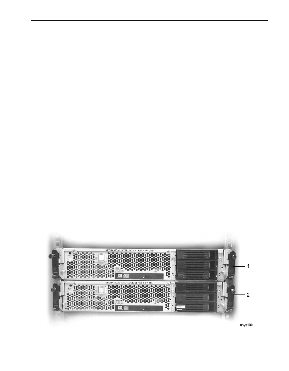
Figure 1-1 shows a system, with its bezel detached.
System Components and CRUs
Each system includes two CPU- I ⁄ O enclosures, as shown in Figure 1-1.
Figure 1-1. Main Enclosures of Express5800/320Ma 3.2 GHz, 3.6 GHz, and Dual-Core Systems
1CPU-I⁄ O enclosure, CPU 0, I/O 10
Overview of Express5800/320Ma 3.2 GHz, 3.6 GHz, and Dual-Core Systems 1-3
Page 16

System Components and CRUs
2CPU-I⁄ O enclosure, CPU 1, I/O 11
Ta bl e 1- 1 lists the systems’ standard CRUs.
Table 1-1. Standard CRUs of Express5800/320Ma 3.2 GHz, 3.6 GHz, and Dual-Core systems
Standard CRUs
Bezel
CPU-I/O enclosures
System backplane assembly
PCI adapters and PCI riser assembly
Internal SATA disk drives
SATA backplane assembly
IDE backplane assembly
CD or DVD drives
CPU fans and PSU fan
VTMs
Modem assembly
Ta bl e 1- 2 lists the systems’ optional CRUs and components.
Table 1-2. Optional CRUs and Components
Optional CRUs and Components Documentation
External USB floppy drive Vendor documentation
EMC CLARiiON and Symmetrix storage
systems
Keyboard-video-mouse (KVM) switch NEC 4-Port KVM Switch: Installation and User’s
Power distribution unit (PDU) Vendor documentation
Vendor documentation and, for the
AX100 storage system, Attaching an EMC
CLARiiON AX100 Storage System to an
Express5800/320Ma System.
Guide
Figure 1-2 shows the front panel of a CPU-I ⁄ Oenclosure.
1-4 Express5800/320Ma: Operation and Maintenance Guide
Page 17
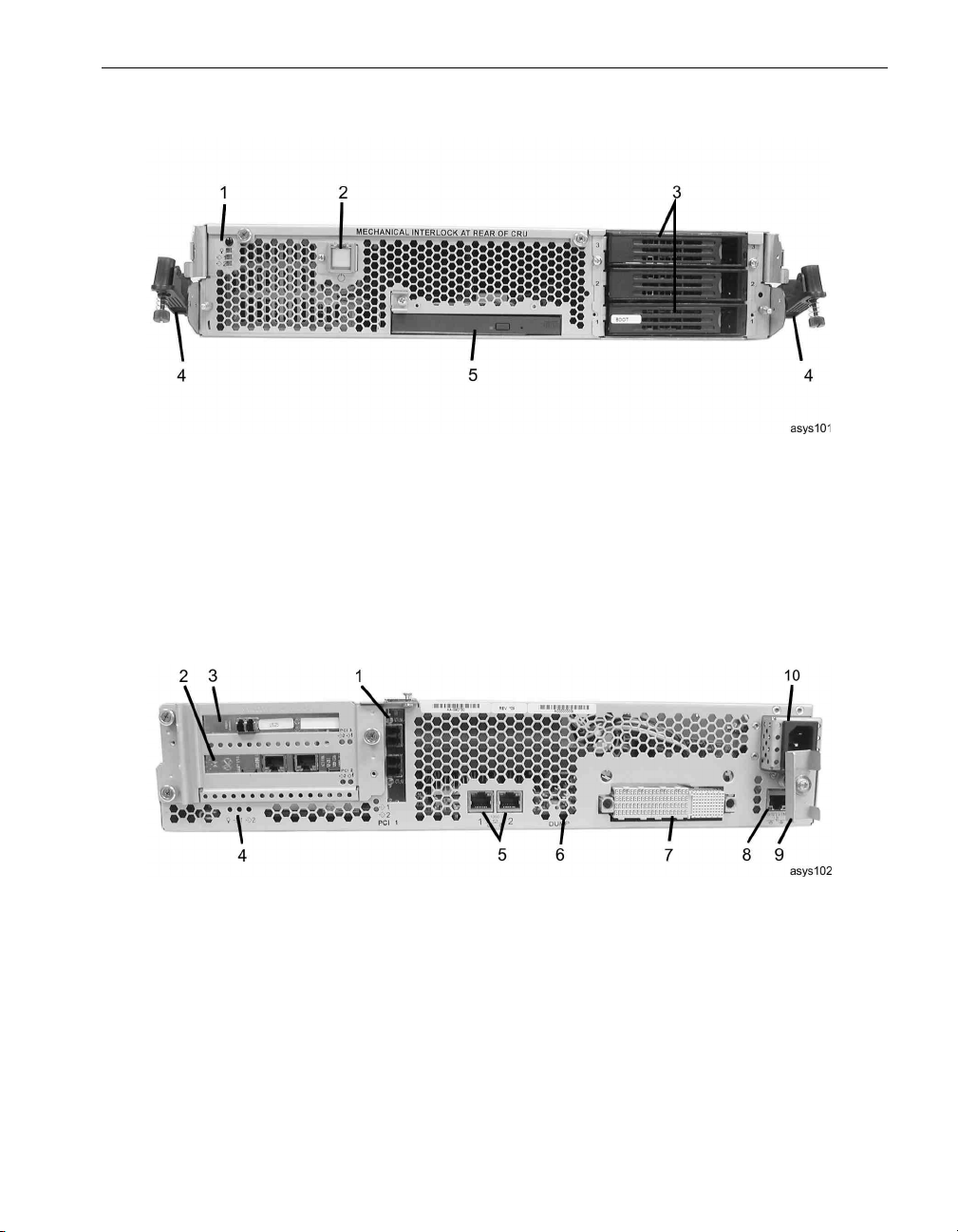
System Components and CRUs
Figure 1-2. CPU-I/O Enclosure: Front Panel
1CPU-I⁄ O enclosure status LEDs (front) 4 Release levers
2 Power button 5 CD or DVD drive
3 SATA disk drives
Figure 1-3 shows the rear panel of a CPU-I ⁄ Oenclosure.
Figure 1-3. CPU-I/O Enclosure: Rear Panel
1 Slot 1, low profile (PCI Slot Info - 9 in ftSMC) 6 Dump button
2 Slot 2, full height† (PCI Slot Info - 10)
3 Slot 3, full height† (PCI Slot Info - 11) 8 10/100-Mbps VTM Ethernet port
4CPU-I⁄ O enclosure status LEDs (rear) 9 Mechanical interlock
5 10/100/1000-Mbps Ethernet ports 10 Power receptacle
† Slots 2 and 3 are located on the PCI riser assembly, which is standard in
Express5800/320Ma 3.6 GHz and Dual-Core, is optional for Express5800/320Ma 3.2 GHz
systems. To add slots 2 and 3 to an Express5800/320Ma 3.2 GHz system, install the
optional AK533 PCI riser assembly kit. See Appendix A.
Overview of Express5800/320Ma 3.2 GHz, 3.6 GHz, and Dual-Core Systems 1-5
7 Backplane connector
Page 18
System Components and CRUs
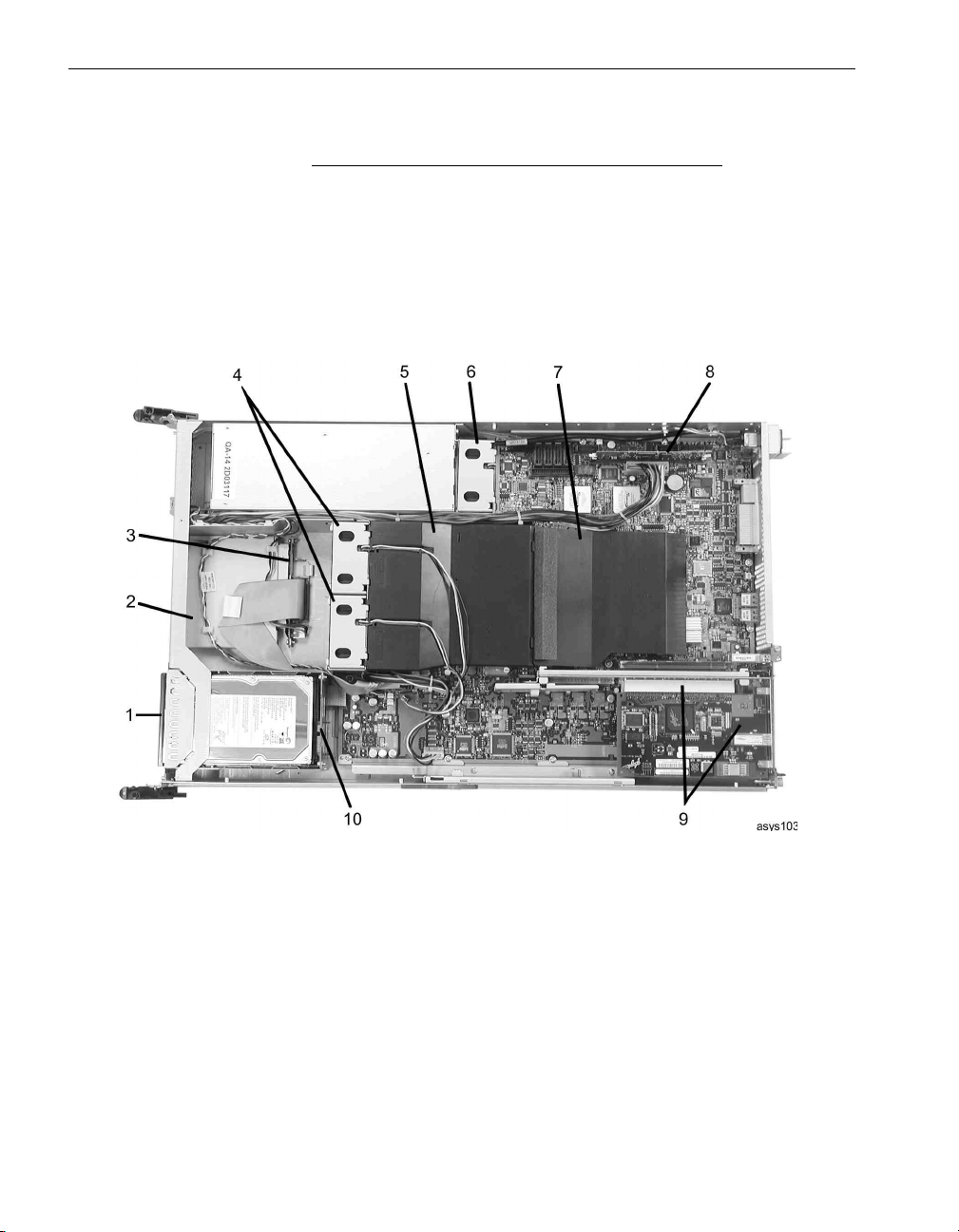
Figure 1-4 shows the internal components of a CPU-I ⁄ Oenclosure.
NOTE
Also see the inside of each CPU- I ⁄ O enclosure cover for
a quick-reference diagram that labels the internal
components of the enclosure.
Figure 1-4. CPU-I/O Enclosure: Interior Components
1 SATA disk drives 6 PSU fan
2 CD/DVD drive bay 7 DIMM baffle
3 IDE backplane assembly 8 VTM
4 CPU fans 9 PCI riser assembly and PCI adapters
5 CPU plenum 10 SATA backplane assembly
Figure 1-5 shows the system backplane assembly, which is located at the rear of the
system. When you insert CPU- I ⁄ O enclosures into the system enclosure, they are
connected to each other by the system backplane assembly.
1-6 Express5800/320Ma: Operation and Maintenance Guide
Page 19
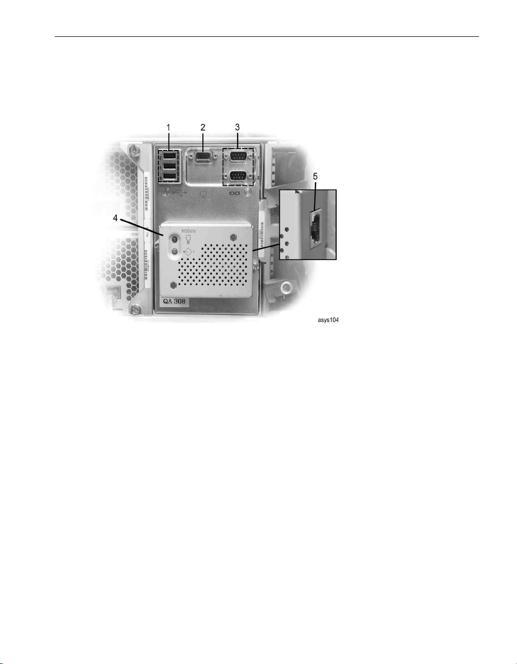
System Components and CRUs
The assembly contains the serial, USB, and VGA ports, as well as a socket for the
detachable modem assembly.
Figure 1-5. System Backplane Assembly
1 USB ports
2 VGA (monitor) port
3 Serial ports
4 Modem assembly
5 Phone line connector
Overview of Express5800/320Ma 3.2 GHz, 3.6 GHz, and Dual-Core Systems 1-7
Page 20

System Components and CRUs
1-8 Express5800/320Ma: Operation and Maintenance Guide
Page 21

Chapter 2
See the following for information about the basic operation of Express5800/320Ma 3.2
GHz, 3.6 GHz, and Dual-Core systems:
• “Standby Power” on page 2-1
• “System Power” on page 2-1
• “Starting Up the System” on page 2-2
• “Shutting Down the System” on page 2-2
• “Fan Speed” on page 2-3
See the vendor documentation for information about operating optional equipment.
Standby Power
When one or both of the system power cords are connected to live AC power outlets,
low-level standby power is present in the system. Standby power enables the primary
BMC controller to monitor the status of system components, even when the system
power is off.
Hardware Operation
2-
Standby power also allows for continuous operation of the VTMs and the modem
assembly; therefore, while the system power is off, administrators can still connect to
the system through the VTMs or the modem assembly to diagnose problems, or to turn
system power on and off from a remote location.
Standby power remains present even after the system has been powered down. To
remove power to the standby devices, remove the power cords.
System Power
Express5800/320Ma 3.2 GHz, 3.6 GHz, and Dual-Core systems have two power
buttons, one on each CPU- I ⁄ O enclosure. Because only one enclosure is the primary
or active enclosure, only one power button is the active button: the one whose LED is
lit (assuming the system has standby power). This button, which you press to start the
system, indicates the primary CPU- I⁄ Oenclosure.
Hardware Operation 2-1
Page 22

Starting Up the System
The system power button is located on the front of the system and functions as follows:
• If the system power is off and standby power is on, pressing the power button turns
the system on and boots the operating system.
• If the system power is on and the operating system or BIOS is starting, stopping,
or running, pressing the power button for several seconds shuts down the system
in the same way as the shut down option from Windows. (Standby power remains
on.)
• If the operating system hangs or a hardware failure occurs, pressing the power
button for several seconds shuts down the system power. (Standby power remains
on.)
NOTE
If you do not want to risk loss of data that might occur from
this action, and if the system contains VTM adapters, you
can attempt less severe actions to restart the system. See
the Express5800/320Ma Virtual Technician Module
User’s Guide for more information.
Starting Up the System
Make sure the system power cords are plugged into live AC outlets.
To boot a system and start the operating system
1. Turn on the monitor and any other peripheral devices.
2. On the CPU- I⁄ O enclosure whose power-button LED is lit, lift the plastic cover that
shields the system power button (number 2 in Figure 1-2) and press the button.
Shutting Down the System
Exit from all applications before shutting down a system.
To shut down a system
1. Click the Start button on the Windows desktop, and then click Shut Down.
2. In the Shut Down Windows dialog box, select Shut Down in the drop-down list,
and then click OK.
3. Turn off power to the monitor and any peripheral devices.
2-2 Express5800/320Ma: Operation and Maintenance Guide
Page 23

Fan Speed
You might notice fan-speed increases in high-temperature environments, during high
system activity periods, or while performing an IPL (loading the operating system
software), shutting down the system, or restarting Windows. The increase in fan speed
ensures adequate cooling under these conditions and is normal behavior.
Fan Speed
NOTE
The system’s standby devices have power even after the
system has been powered down. To remove power to the
standby devices, you must remove the power cords.
Hardware Operation 2-3
Page 24

Fan Speed
2-4 Express5800/320Ma: Operation and Maintenance Guide
Page 25

Chapter 3
See the following sections for information about troubleshooting Express5800/320Ma
3.2 GHz, 3.6 GHz, and Dual-Core systems:
• “System LEDs” on page 3-1
• “General Disk Drive Problems and Solutions” on page 3-12
• “CD- or DVD-Drive Problems and Solutions” on page 3-13
• “Using the Dump Button to Create a Dump File” on page 3-15
System LEDs
System LEDs are located on the front and rear of each CPU-I ⁄ O enclosure.
The LEDs can be single-color or bicolor:
• Single-color LEDs are green, amber, or white.
• Bicolor LEDs can be green or amber.
Troubleshooting the Hardware
3-
At any time, the LEDs can also have one of three different states:
• Unlit, or OFF
• Steady on, or ON
• Blinking
You can determine the state of a particular component by interpreting the combinations
of LED colors and states. For example, you can determine if system components are
operating in duplex or simplex mode. Duplex mode means that the components are
partnered and the partner is operating properly. Simplex mode means that the partner
failed or was removed.
Ta bl e 3- 1 describes the general meaning of the LED colors and states.
Troubleshooting the Hardware 3-1
Page 26

System LEDs
Table 3-1. General Status LED Meanings
LED Color
(Purpose) LED State CRU State
Green
(Power indicator)
Amber
(Fault/Identify
indicator)
White
(Simplex/Duplex
indicator)
Unlit Offline or unpowered
Blinking Green Offline with standby power (enclosure)
Duplexed and active (disk drive)
Steady Green Online and functioning normally
Duplexed and inactive (disk drive)
Unlit Offline or functioning normally
Steady Amber Broken or partially broken
Blinking Amber Simplexed and unsafe to remove (disk drive)
Component is being identified
Unlit or steady white Duplexed and safe to remove
Blinking white Simplexed and unsafe to remove
For more specific information about each status LED and actions you can take
depending on the state of the system, see one of the following sections:
• “CPU-I/O Enclosure Status LEDs” on page 3-3
• “SATA Disk-Drive LED” on page 3-5
• “PCI Slot Status LEDs” on page 3-7
• “Ethernet Port and VTM Port LEDs” on page 3-8
• “Modem Assembly LEDs” on page 3-10
See Chapter 2, “Hardware Operation” for information about the LED in the system
power button.
For information about LEDs in optional components, see the vendor documentation.
3-2 Express5800/320Ma: Operation and Maintenance Guide
Page 27
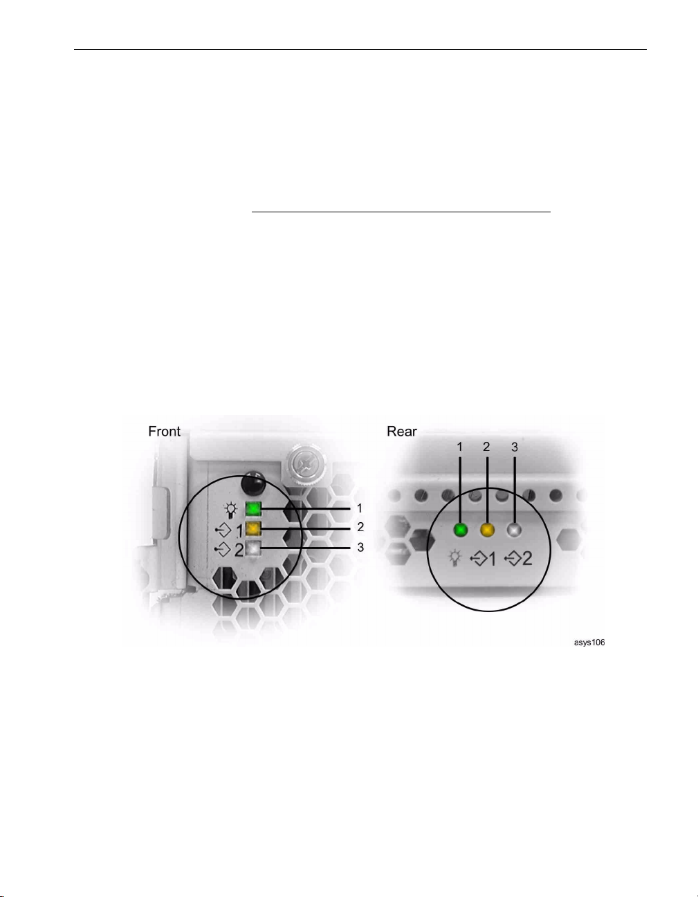
CPU-I/O Enclosure Status LEDs
Each CPU- I ⁄ O enclosure contains three LEDs that describe the status of the
components in the enclosure, including the CPU, BMC, VTM, PCI adapters, and SATA
disk drives. These LEDs, which are located on the front and rear of each enclosure, are
green, amber, and white. The CPU-I ⁄ O enclosure status LEDs are shown in
Figure 3-1 and described in Tab le 3- 2.
NOTE
During the boot process, the BMC verifies that all devices
in the CPU- I ⁄ O enclosures are present and performing
normally before the BMC activates that enclosure. If a
component has failed, the BMC removes power from that
enclosure. As a result, the LEDs on an enclosure might
turn on briefly and then turn off, or the LEDs might not turn
on at all, indicating a failed component of the enclosure.
Figure 3-1. CPU-I/O Enclosure Status LEDs
System LEDs
1 Green LED (power indicator)
2 Amber LED (fault/identify indicator)
3 White LED (simplex/duplex indicator)
Troubleshooting the Hardware 3-3
Page 28

System LEDs
Table 3-2. CPU-I/O Enclosure Status LEDs
LED and State Description/Action
Green, unlit Power off or no standby power.
Green, blinking Standby power.
Green, steady Online or booting.
Amber, unlit Offline or functioning normally.
Amber, steady Broken or partially broken components (CPU, BMC, VTM, PCI adapter, or
Action: If necessary, verify that the AC power cords are connected at
both ends. Verify that the system power connections are seated properly.
Action: Press the power button to boot the system.
SATA disk drive) in the enclosure.
Action: Refer to ftSMC for information about the failure, then attempt to
correct the failure within the operating system. For help in interpreting the
information displayed in ftSMC, see the Help for ftSMC and
Express5800/320Ma: System Administrator’s Guide. If you need to
remove an enclosure for troubleshooting, first determine if it is safe to pull
by verifying the state of the white status LED.
the
If you are unable to fix the condition, contact NEC Technical Support or
your authorized service representative.
Amber, blinking Either the CPU element or the I/O element is being identified from a
command in ftSMC.
For more information about locating a component by flashing an LED, see
the Help for ftSMC or the Express5800/320Ma: System Administrator’s
Guide.
White, unlit Safe to remove, offline or power off.
White, steady Operating in duplex mode. If system power is off (green blinking LED), the
BMC and VTM are operating in duplex mode.
It is safe to remove the enclosure, because its partner keeps the system
operational.
3-4 Express5800/320Ma: Operation and Maintenance Guide
Page 29
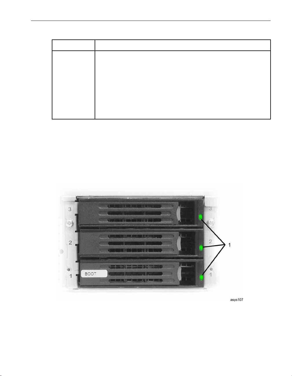
Table 3-2. CPU-I/O Enclosure Status LEDs (Continued)
LED and State Description/Action
White, blinking Operating in simplex mode.
SATA Disk-Drive LED
Each CPU- I ⁄ O enclosure can support up to three internal SATA disk drives. Each
SATA disk drive has a single green-amber LED (number 1 in Figure 3-2) on its bezel.
Ta bl e 3- 3 describes the SATA disk drive LED states.
Figure 3-2. SATA Disk-Drive LED
System LEDs
If system is on (steady green LEDs), removing the enclosure will crash
the system because no partner is available.
If system power is off (green blinking LED), either the BMC or the VTM is
operating in simplex mode. If you remove the enclosure, you cannot
power the system on, or access the system remotely.
Action: Return the offline partner component to service.
1 SATA Disk Drive LEDs
Troubleshooting the Hardware 3-5
Page 30

System LEDs
Table 3-3. SATA Disk Drive LED
State Description/Action
Unlit Not powered, safe to pull.
Green, steady Duplexed and inactive, safe to pull.
Green, blinking Duplexed and active, safe to pull.
Amber, steady Broken and safe to pull.
Amber, blinking Simplexed and unsafe to pull for one of the following reasons:
Action: Verify that the drive is properly installed. Verify the connection
by removing and replacing the drive.
Refer to ftSMC for information about the failure and attempt to correct
the failure in the operating system. For help in interpreting the
information displayed in ftSMC, see the Help for ftSMC and
Express5800/320Ma: System Administrator’s Guide. If necessary,
replace the drive with a new one.
If you are unable to fix the condition, contact NEC Technical Support or
your authorized service representative.
the
– If the drive is part of a Rapid Disk Resync (RDR) drive pair, the
partner drive is unavailable.
Action: Reinsert the partner drive to restore duplex operation.
Verify that the partner drive is functioning normally.
– If the drive is not part of an RDR pair, a non-mirrored volume
exists on the drive. Or, a mirrored volume exists on the drive, but its
partner volume is unavailable.
Action: If the drive contains a mirrored volume, reinsert the drive
that contains its partner volume to restore duplex operation. If the
drive is not mirrored, consider creating an RDR drive pair or
another type of mirrored set to increase fault tolerance.
– If the drive is part of an RDR drive pair or it contains part of a
mirrored volume pair, the drive or volume is resynchronizing.
Action: Wait for the process to complete.
For information about RDR and mirrored volumes, see the
Express5800/320Ma: System Administrator’s Guide.
See “General Disk Drive Problems and Solutions” on page 3-12 for additional
troubleshooting information.
3-6 Express5800/320Ma: Operation and Maintenance Guide
Page 31

PCI Slot Status LEDs
Each PCI slot has two LEDs, one amber LED and one white LED, that indicate the
status of the PCI slot. The PCI slot status LEDs are adjacent to each PCI slot at the
rear of the enclosure, as shown in Figure 3-3.
NOTE
Figure 3-3 shows a system that contains PCI slots 2
and 3.
Figure 3-3. PCI Slot LEDs
System LEDs
1 Amber LED (fault/identify indicator)
2 White LED (simplex/duplex indicator)
Ta bl e 3- 4 describes the PCI slot status LED states.
Troubleshooting the Hardware 3-7
Page 32

System LEDs
Table 3-4. PCI Slot Status LEDs
LED and State Description/Action
Amber, unlit Operating normally, or slot is empty.
Amber, steady PCI adapter or slot has failed.
Amber, blinking PCI slot is being identified from a command in ftSMC.
White, unlit Offline.
Action: Refer to ftSMC for information about the failure and attempt to
correct the failure in the operating system. For help in interpreting the
information displayed in ftSMC, see the Help for ftSMC and
Express5800/320Ma: System Administrator’s Guide. If necessary,
replace the PCI adapter.
If you are unable to fix the condition, contact NEC Technical Support or
your authorized service representative.
For more information about locating a component by flashing an LED, see
the Help for ftSMC or the Express5800/320Ma: System Administrator’s
Guide.
the
White, steady Operating in duplex mode.
White, blinking Operating in simplex mode and unsafe to remove. Taking it offline will
result in lost connectivity.
Action: If necessary, insert an identical adapter in the corresponding slot
in the other enclosure to enable duplex mode.
Ethernet Port and VTM Port LEDs
Each CPU- I ⁄ O enclosure contains up to three Ethernet ports. Two ports, which
operate at 10, 100, or 1000 Mbps, are connected to the embedded Ethernet controller.
Another port, which operates at 10 or 100 Mbps, is dedicated to the VTM (if installed).
Each port has two integrated LEDs that indicate Ethernet activity and connection
speed.
The Ethernet ports and the VTM port are shown in Figure 3-4. Tab le 3 - 5 and Ta b le 3 -6
describe the system Ethernet port LED states and VTM port LED states, respectively.
3-8 Express5800/320Ma: Operation and Maintenance Guide
Page 33

Figure 3-4. Ethernet Port and VTM Port LEDs
1 Ethernet port ACT/LINK LED 3 VTM port 10/100-Mbps LED
2 Ethernet port 10/100/1000-Mbps LED 4 VTM port ACT/LINK LED
Table 3-5. Ethernet Port LED States
System LEDs
Function (Location) Color and State Description
ACT/LINK (Left) Unlit Link not present
Green, steady Link present
Green, flashing Ethernet activity
10/100/1000 (Right) Unlit 10-Mbps connection
Green, steady 100-Mbps connection
Amber, steady 1000-Mbps connection
Amber, flashing Identifies the PCI adapter when you click on
Identify Adapter on the General tab in the
PROSet utility.
Troubleshooting the Hardware 3-9
Page 34

System LEDs
Table 3-6. VTM Port LED States
Function (Location) Color and State Description
10/100 (Left) Unlit 10-Mbps connection
ACT/LINK (Right) Unlit Link not present
Modem Assembly LEDs
When present, a single modem assembly is attached to the system backplane
assembly at the rear of the system. The modem assembly has two LEDs: a green
power LED and an amber fault LED (Figure 3-5).
Figure 3-5. Modem Assembly LEDs
Green, steady 100-Mbps connection
Green, steady Link present
Green, flashing Ethernet activity
1 Green LED (power indicator)
2 Amber LED (fault/identify indicator)
Ta bl e 3- 7 describes the modem assembly LED states.
3-10 Express5800/320Ma: Operation and Maintenance Guide
Page 35

CAUTION
!
Do not remove the modem assembly when it is powered
on (steady green LED). For information about removing
and replacing a modem assembly, see “Replacing or
Installing a Modem Assembly” on page 5-49.
Table 3-7. Modem Assembly LEDs
LED and State Description/Action
Green, unlit Powered off and safe to pull.
Green, steady Powered on and unsafe to pull.
Action: If you need to replace the modem, either turn the modem power
off or shut down the system and unplug the power cords. For information
about removing and replacing a modem assembly, see “Replacing or
Installing a Modem Assembly” on page 5-49.
Amber, off Operating normally.
Amber, steady Broken or hung.
System LEDs
Action: Refer to ftSMC for information about the failure and attempt to
correct the failure in the operating system. For help in interpreting the
information displayed in ftSMC and, if necessary, resetting the modem,
see the Help for ftSMC and the
Administrator’s Guide. If necessary, replace the modem assembly.
If you are unable to fix the condition, contact NEC Technical Support or
your authorized service representative.
Amber, blinking Modem is being identified.
See the Express5800/320Ma: System Administrator’s Guide for the
procedure to identify a modem.
Express5800/320Ma: System
Troubleshooting the Hardware 3-11
Page 36

General Disk Drive Problems and Solutions
General Disk Drive Problems and Solutions
Ta bl e 3- 8 lists some possible problems that the internal SATA disk drives may
encounter, as well as some corrective actions.
Table 3-8. Troubleshooting Disk Drives
Problem Action
System will not boot
from system disk
Cannot access data Some files might contain viruses. Run a virus-scan utility on the disk drive.
Disk drive fails, or disk
status LED is steady
amber
System does not
recognize disk drive
Ensure that the disk-drive boot is enabled through the BIOS setup
program.
Try to boot from the system disk’s mirrored partner. To do so, unlatch the
suspected faulty system disk.
Some files might be corrupted. If possible, restore the files from a backup.
If there is a problem with the system files, and you have an Automated
System Recovery (ASR) backup, use the ASR backup to repair the system
files. See the Help for Windows for more information.
Use the System event log and ftSMC to try to determine what might have
caused the disk drive to fail. For more information about the System event
log and ftSMC, see the Help for Windows and the Express5800/320Ma:
System Administrator’s Guide. If you cannot resolve the problem, contact
NEC Technical Support or your authorized service representative.
Ensure that the disk drive was installed correctly. See “Removing and
Inserting a SATA Disk Drive” on page 5-32 and “Removing and Replacing
a CD or DVD Drive” on page 5-36 for information about installing a disk
drive. For external floppy disk drives, ensure that the USB cable is plugged
into the USB connectors on the system backplane assembly. Note that you
cannot connect the floppy drive through the USB connectors on the
keyboard.
3-12 Express5800/320Ma: Operation and Maintenance Guide
Page 37

CD- or DVD-Drive Problems and Solutions
Table 3-8. Troubleshooting Disk Drives (Continued)
Problem Action
Slow response time The disk drive might be full. Ideally, at least 15 percent of the disk drive
should be free for system activity. Delete unnecessary files, or move files
to another disk drive.
You might need to defragment the disk drive.
Mirror regeneration might be occurring. Try to schedule mirror
regeneration for a time when the system is not heavily used. However, if
the disk contains business-critical data, you should regenerate the mirrors
as soon as possible.
The disk drive might be reading a compressed file. In the future, avoid
compressing files that are heavily used.
Many read or write operations might be queued to the disk drive. If the
Express5800/320Ma Software Availability Manager indicates an unusually
high number of disk requests outstanding, you should examine how your
applications are using the disks. For more information about the
Express5800/320Ma Software Availability Manager, see the
Express5800/320Ma Software Availability Manager User’s Guide.
Errors might be occurring on the drive. Check the system event log.
CD- or DVD-Drive Problems and Solutions
The CD or DVD drive has a single LED that indicates whether the drive is busy. It does
not have an LED that indicates whether a fault has occurred.
Ta bl e 3- 9 lists some possible problems that the CD-ROM drive could encounter, as well
as some corrective actions.
Troubleshooting the Hardware 3-13
Page 38

CD- or DVD-Drive Problems and Solutions
Table 3-9. Troubleshooting the CD or DVD Drive
Problem Action
CD-ROM drive is not
working properly
System cannot read CD
or DVD
CD or DVD drawer will
not open
Ensure that the CD or DVD has been inserted correctly.
Ensure that the CD or DVD has been inserted into the correct
drive, and that you are accessing the correct drive on the
Windows desktop.
Check for environmental problems that can damage CD or DVD
media and drive heads. Environmental problems can result from
airborne contaminants (smoke, steam, dust, and ashes) or
radiated interference (hand-held receivers, communications and
radar installations, and radio/television broadcast transmitters).
Check that no paper or plastic label, or any residue, is attached to
the surface of the CD or DVD that is in use.
Ensure that the correct drivers are installed.
Ensure that the CD or DVD drive was installed correctly. See
“Removing and Replacing a CD or DVD Drive” on page 5-36 for
more information.
Ensure that the CD or DVD is clean and does not contain any
scratches. Attempt to read a known good CD or DVD.
If you are attempting to load a DVD, verify that the drive is a DVD
drive by checking the logo on the front panel of the drive.
Insert a straightened paper clip into the emergency eject hole.
System will not boot
from CD or DVD drive
Busy Indicator stays on Ensure that the CD or DVD has been inserted correctly.
3-14 Express5800/320Ma: Operation and Maintenance Guide
Ensure that CD boot is enabled through the BIOS Setup
program.
Ensure that the CD or DVD drive is operating properly by
attempting the same operation with a different CD or DVD. If the
second CD or DVD works, the first one might be damaged.
Page 39

Using the Dump Button to Create a Dump File
Using the Dump Button to Create a Dump File
To enable NEC Technical Support or your authorized service representative to
diagnose problems with your system, you might need to create a snapshot, or dump
file, of the system’s memory while the system is running.
One method for creating a dump file on a system is to press the dump button on its
primary CPU- I ⁄ O enclosure (the enclosure with a lit power button). The dump button
is located inside a pin-hole opening (Figure 3-6) at the rear of each enclosure. You
need a fine-tipped object, such as an unfolded paper clip or pushpin, to reach the
button.
Figure 3-6. Pressing the Dump Button
NOTE
Because the dump button reboots the entire system, you
need to schedule downtime for this procedure. If your
CPU- I ⁄ O enclosures are duplexed, you might prefer to
use the Dump and Go command in ftSMC, which can
dump system memory while keeping the system online.
For more information, see the Express5800/320Ma:
System Administrator’s Guide or the Help for ftSMC.
To create a dump file, press and hold the dump button for at least three seconds, but
no longer than eight seconds, then release it. In response, the system:
Troubleshooting the Hardware 3-15
Page 40

Using the Dump Button to Create a Dump File
• Goes offline with its memory intact
• Dumps a snapshot of the memory to C:\sradumps\Memoryn.dmp
• Reboots and returns to online status
To ensure that the system generates a dump file, verify that you have not changed the
following default settings in ftSMC under Drivers, Board Instance Driver - srabid:
• DumpQuickEnabled = True
• DumpNumberOfFilesToSave = 2 (must be greater than 0)
If you use the dump button incorrectly, or if the button is pressed by mistake, the system
ignores the dump signal and, ultimately, deactivates the button to prevent the system
from crashing, as follows:
• If you tap the button, hold it for less three seconds, or hold it for longer than eight
seconds, the system counts this as a spurious signal and ignores it.
• If you press the button more than once within a five-second period, the system also
counts this as a spurious signal and ignores it.
• If seven spurious activations occur within a 24-hour period, the system disables the
dump button (only on the enclosure where it was activated) and sends an alert to
NEC Technical Support or your authorized service provider.
All spurious signals from the dump button and the deactivation alert are logged in the
Application event log for the operating system.
The system resets the spurious signal count and re-enables the dump button only if you
reset the Base Management Controller (BMC) for the enclosure. To reset the BMC,
take the affected enclosure offline, remove and replace it, then bring it online again.
NOTE
If you intend to generate a dump file for an enclosure
where the dump button has been disabled, you should
use another method to save the dump file before resetting
the BMC, because you might lose valuable
troubleshooting data by doing so.
3-16 Express5800/320Ma: Operation and Maintenance Guide
Page 41

Using the Dump Button to Create a Dump File
To generate a dump file when the dump button on the primary enclosure is disabled,
do one of the following:
• In ftSMC, select the CPU node for the primary enclosure, then select Dump and
Go from its Action Menu. For more information, see the Express5800/320Ma:
System Administrator’s Guide and the online help for ftSMC.
• On a system that contains VTMs, open a VTM session to the primary enclosure
and click NMI (non-maskable interrupt) on the Troubleshoot Server tab. For more
information, see the Express5800/320Ma Virtual Technician Module User’s Guide.
Troubleshooting the Hardware 3-17
Page 42

Using the Dump Button to Create a Dump File
3-18 Express5800/320Ma: Operation and Maintenance Guide
Page 43

Chapter 4
General servicing information is discussed in the following sections:
• “Unpacking CRUs” on page 4-1
• “Storing CRUs” on page 4-2
• “Repacking CRUs” on page 4-3
• “Replacing a CRU” on page 4-3
• “General Safety Precautions” on page 4-4
See Chapter 5, “CRU Replacement Procedures” for detailed information.
Unpacking CRUs
Upon receiving a CRU, perform the following:
• Inspect the packing slip to ensure that the correct CRU was received.
• Inspect the packing container for damage.
General Servicing Information
4-
• Check the shipping impact indicators to ensure that they have not been activated
(see Figure 4-1).
If any of the following conditions apply to your shipment, see “Using the Dump Button
to Create a Dump File” on page 3-15:
• The package is damaged.
• An impact indicator has been activated.
• You received the wrong shipment.
If there are no problems, unpack the CRU.
General Servicing Information 4-1
Page 44

Storing CRUs
Figure 4-1. Shipping Impact Indicators
To unpack the CRU
1. While observing any printed directions or warnings, carefully open the package.
2. Carefully remove the protective packaging and save it for possible reuse in storing
3. Verify that you received the correct CRU by checking the packing slip and the bar
4. Inspect the CRU for shipping damage.
HANDLE
WITH CARE
WARNING
or returning a CRU.
code label on the CRU.
TIP-N-TELL
UP
msys034
5. If the CRU is wrapped in an antistatic bag, keep it in the bag until it is installed. If
you are not going to install the CRU immediately, protect it from damage by
repacking it in its shipping package.
Storing CRUs
If you need to store a CRU, keep it in the protective packaging and take the following
precautions:
• Ensure that the CRU is right-side up by following the directions on the carton.
• Comply with all warning labels.
• Avoid placing the CRU in a location where heavier items might be placed on it.
• Protect the CRU from exposure to dust, electromagnetic fields, vibrations, extreme
heat, or any other environmental conditions that might damage the CRU.
• Avoid prolonged storage that could reduce the useful life of the CRU.
If you are uncertain about the proper storage conditions for a specific CRU, see “Using
the Dump Button to Create a Dump File” on page 3-15.
4-2 Express5800/320Ma: Operation and Maintenance Guide
Page 45

Repacking CRUs
When returning a defective or incorrect CRU, package the CRU using the original
packing materials or the replacement-CRU packing materials. Ensure that the CRU is
adequately protected from the following:
• Dents, scratches, and impact damage
• Magnetic fields and static electricity
• Accidental opening of the package in transit
• Detachment of the address label
If you are uncertain that the CRU will be adequately protected during shipment, see
“Using the Dump Button to Create a Dump File” on page 3-15. Also, see “Using ESD
Precautions” on page 5-2 for information about how to protect components from
exposure to static electricity.
Replacing a CRU
Before replacing a CRU, do the following:
• Confirm that the CRU has failed and needs to be replaced. You can view failure
information from the status LEDs on each hardware component and from your
system’s event or error logs.
• Determine if a component needs to be taken out of service. Refer to your system
administration or analysis documentation to remove the component from service
via software before removing it physically.
• Take proper grounding precautions. When handling components, especially those
with exposed integrated circuits, use proper grounding procedures to avoid
electrostatic discharge (ESD) damage to the component. See “Using ESD
Precautions” on page 5-2.
• Observe the proper safety precautions. Follow the precautions listed in “General
Safety Precautions” on page 4-4.
Repacking CRUs
After replacing a CRU, do the following:
• Replace the bezels, if applicable, and close the cabinet doors.
• Place the component in service if it is out of service.
• Verify system operation.
• Package and ship the failed component. See “Repacking CRUs” on page 4-3.
General Servicing Information 4-3
Page 46

General Safety Precautions
General Safety Precautions
• To help identify problems that might occur during the CRU removal and
replacement, read the entire procedure before performing it.
• Provide the space and illumination necessary to safely perform the procedure.
• Conduct all activities in compliance with all applicable industry safety standards
and practices.
• When performing maintenance procedures, do not wear conductive articles or
material such as rings, bracelets, keys, chains, garments with metallic thread, and
so forth.
4-4 Express5800/320Ma: Operation and Maintenance Guide
Page 47

Chapter 5
CRU Replacement Procedures
Express5800/320Ma 3.2 GHz, 3.6 GHz, and Dual-Core systems accommodate safe
and easy removal, replacement, and addition of customer-replaceable units (CRUs).
CRU replacement procedures are discussed in the following sections:
• “Before Replacing CRUs” on page 5-1
• “Removing and Replacing the Bezel” on page 5-3
• “Removing and Replacing a CPU-I/O Enclosure” on page 5-4
• “Replacing the System Backplane Assembly” on page 5-10
• “Removing and Replacing a CPU-I/O Enclosure Cover” on page 5-15
• “Replacing or Installing a PCI Adapter” on page 5-18
• “Removing and Replacing the PCI Riser Assembly” on page 5-26
• “Removing and Inserting a SATA Disk Drive” on page 5-31
• “Replacing a SATA Backplane Assembly” on page 5-33
• “Removing and Replacing a CD or DVD Drive” on page 5-35
• “Replacing an IDE Backplane Assembly” on page 5-37
5-
• “Replacing a CPU Fan” on page 5-41
• “Replacing a Power Supply Unit Fan” on page 5-44
• “Replacing or Installing a VTM” on page 5-47
• “Replacing or Installing a Modem Assembly” on page 5-48
Before Replacing CRUs
Observe the following warnings, cautions, and notes when replacing or adding CRUs.
WARNING
!
If a component is not a CRU, do not attempt to remove
or replace it. Doing so may result in serious personal
injury and/or damage to the system.
CRU Replacement Procedures 5-1
Page 48

Before Replacing CRUs
!
!
WARNING
RISK OF EXPLOSION IF BATTERY IS REPLACED BY
AN INCORRECT TYPE. DISPOSE OF USED
BATTERIES ACCORDING TO THE INSTRUCTIONS
PROVIDED WITH THE BATTERY.
CAUTION
When replacing a CRU, always observe the following
guidelines.
• Do not remove a CRU when its white LED is blinking. This indicates
that the CRU is operating in simplex mode (its duplex partner is not
functional). Removing the CRU would cause the system to fail.
• Observe ESD handling precautions if they are indicated for the
procedure.
• Read the entire procedure so that you fully understand it. If any part
of the procedure is not clear, see “Using the Dump Button to Create a
Dump File” on page 3-15.
• When necessary, refer to your system administration documentation
for instructions in how to identify a failed component and take it offline
before servicing it.
NOTE
A quick-reference diagram on the inside of each
CPU- I ⁄ O enclosure cover labels the internal components
of the enclosures. Refer to the diagram when replacing a
CRU to determine the route of cables from the CRU to the
connectors on the main board of the enclosure. On this
diagram, connectors are identified by circuit board
junction, for example, J16 is the power connector for a
CPU fan.
Using ESD Precautions
Doing work inside an uncovered CPU- I ⁄ O enclosure exposes electronic components
to potential damage from ESD.
5-2 Express5800/320Ma: Operation and Maintenance Guide
Page 49

Tools
Removing and Replacing the Bezel
CAUTION
!
To avoid damaging ESD-sensitive components during
handling, always take the following precautions.
1. Ground yourself before working inside an enclosure. Put a grounding strap on your
wrist and attach its other end to some suitable grounding point, such as a
computer-system cabinet.
2. Discharge static electricity by touching an unpainted portion of the enclosure or
system just before handling ESD-sensitive parts.
3. Store PCI adapters in their static-protective envelope until you are ready to install
them in the system.
4. Hold a PCI adapter by its edges.
Although you can replace some CRUs without the use of tools, others require use of
the following tools:
• An ESD strap
• A #2 or #1 Phillips head screwdriver
Removing and Replacing the Bezel
The systems have a single removable bezel that attaches to the face of both
CPU- I ⁄ O enclosures.
Estimated time: One minute.
Tools: None.
To remove the bezel
1. Grasp the bezel on its right and left sides if the system is in a rack, or on its top and
bottom sides if the system is in a pedestal case.
2. Pull the bezel straight toward you (Figure 5-1) until it snaps free from the ball studs.
3. If you are replacing a defective bezel, set it aside for repacking. See “Repacking
CRUs” on page 4-3.
CRU Replacement Procedures 5-3
Page 50

Removing and Replacing a CPU-I/O Enclosure
Figure 5-1. Removing the Bezel
To attach the bezel
1. At the front of the system, align the bezel with its location on the system frame.
Align the LED light pipes inside the bezel with the left side of the system if it is in a
rack, or with the bottom of the system if it is in a pedestal case.
2. Press the U-shaped openings on the inside of the bezel into the ball studs on the
mounting rails until the bezel snaps into place.
Removing and Replacing a CPU-I/O Enclosure
Remove a CPU- I ⁄ O enclosure to replace it or to access its internal components for
other procedures.
See the following sections:
• “Removing a CPU-I/O Enclosure” on page 5-5
• “Replacing a CPU-I/O Enclosure” on page 5-8
Estimated time: Five minutes, not including the time for other CRU replacement
procedures.
Tools: None.
5-4 Express5800/320Ma: Operation and Maintenance Guide
Page 51

Removing a CPU-I/O Enclosure
WARNING
!
To avoid personal injury or damage to the system, two
persons are required to replace an enclosure.
1. If necessary, use ftServer Management Console (ftSMC) to take the enclosure
offline. See the Help for ftSMC for detailed instructions.
Verify that the enclosure is offline before proceeding.
2. Remove the bezel, as described in “Removing and Replacing the Bezel” on
page 5-3.
3. Disconnect all of the data cables from the rear of the enclosure. Then, disconnect
the power cord.
CAUTION
!
You must disconnect the VTM network cable before you
disconnect the power cord. When you remove the power
cord, the mechanical interlock at the rear of the system
springs into the unlocked position and could damage the
VTM connector or cable (Figure 5-2, inset).
Removing and Replacing a CPU-I/O Enclosure
4. Ensure that the mechanical interlock on the rear of the enclosure is in the unlocked
position (number 1 in Figure 5-2). If the system is in a rack, the unlocked position
is the vertical position. If the system is in a pedestal case, the unlocked position is
the horizontal position.
CRU Replacement Procedures 5-5
Page 52

Removing and Replacing a CPU-I/O Enclosure
Figure 5-2. Unlocking the Rear Interlock on an Enclosure
1 Mechanical interlock (unlocked position)
2 Mechanical interlock (locked position)
3 VTM Ethernet cable
5. Loosen the two thumbscrews (number 1 in Figure 5-3) on the release levers at the
front of the enclosure.
6. Pull on the two release levers to loosen the enclosure from the rails (number 2 in
Figure 5-3). Pull the enclosure a few inches out of the slot.
5-6 Express5800/320Ma: Operation and Maintenance Guide
Page 53

Removing and Replacing a CPU-I/O Enclosure
Figure 5-3. Unlocking the Front Release Levers on an Enclosure
1 Thumbscrew
2 Release lever (unlocked)
7. With one person supporting the enclosure on each side, pull it straight out until it is
stopped by the safety lever (Figure 5-4) on its right side. Push down the front end
of the lever to disengage it.
Figure 5-4. Removing a CPU-I/O Enclosure
1 Safety lever
8. With each person holding a side of the enclosure, pull the enclosure straight out
and place it on a flat, stable surface.
CRU Replacement Procedures 5-7
Page 54

Removing and Replacing a CPU-I/O Enclosure
If you are replacing the CPU- I ⁄ O enclosure with a new enclosure, transfer the SATA
drives, the CD or DVD drive, the VTM (if applicable), the PCI riser assembly (if
applicable), and the PCI adapters from the old enclosure to the new enclosure.
NOTES
1. Before you remove the SATA disk drives from the old
enclosure, label the drives on the bezel of each drive
to ensure that you can replace them in the proper
order. The numerical slot designation for each disk is
noted on the front of the SATA drive bay.
2. When you remove the PCI riser assembly from the old
enclosure, you do not need to remove the PCI
adapters from it. Transfer the entire PCI riser
assembly, with adapters, to the replacement system.
3. The replacement enclosure will contain the same
CPU and memory configuration as the enclosure you
are replacing. Do not remove processors or memory
modules from the enclosure when you return it to
NEC Solutions (America), Inc.
Refer to the following sections for more information:
• “Replacing or Installing a PCI Adapter” on page 5-18
• “Removing and Replacing the PCI Riser Assembly” on page 5-26
• “Replacing or Installing a VTM” on page 5-47
• “Removing and Inserting a SATA Disk Drive” on page 5-31
• “Removing and Replacing a CD or DVD Drive” on page 5-35
When you are finished removing components from the old CPU- I⁄ O enclosure, set
it aside for repacking. See “Repacking CRUs” on page 4-3.
Replacing a CPU-I/O Enclosure
NOTES
1. The first CPU- I ⁄ O enclosure to complete power up is
the primary (boot) enclosure: the LED in its power
switch will be lit.
2. Each CPU- I⁄ O enclosure is identical (aside from
installed options) and may occupy either of the two
enclosure slots.
5-8 Express5800/320Ma: Operation and Maintenance Guide
Page 55

Removing and Replacing a CPU-I/O Enclosure
WARNING
!
To avoid personal injury or damage to the system, two
persons are required to replace an enclosure.
1. Ensure that the mechanical interlock on the rear of the enclosure is in the unlocked
position (number 1 in Figure 5-2).
2. With one person supporting the enclosure on each side, align the rear end of the
enclosure with the appropriate rails on both sides (Figure 5-4). The enclosure
should be perfectly level.
3. With the release levers in the open position (number 2 in Figure 5-3), slide the
enclosure almost all the way into its opening.
4. Position the lower ends of the release levers over the inside edge of the positioning
pins, then push the release levers into their fully-closed position to push the
enclosure into place.
5. Tighten the two thumbscrews (number 1 in Figure 5-3) to lock the enclosure
securely into the backplane.
6. Turn the mechanical interlock on the rear of the system into the locked position
(number 2 in Figure 5-2), and plug in the power cord.
7. Plug in all of the data cables.
8. Restore the enclosure to service in ftSMC.
CAUTION
!
When you plug the power cord into the
CPU- I ⁄ Oenclosure, its white LED will blink for about 30
seconds while its BMC is synchronizing. Do not remove
the enclosure during this process! If the white LED
continues to blink for several minutes, contact NEC
Technical Support or your authorized service
representative.
9. Ensure that the enclosure and any CRUs you replaced are functioning properly.
• Verify that all installed options appear in ftSMC, and, if applicable, that they are
operating in Duplex mode. (Note that it could take the system several minutes
to update the status of all the devices in ftSMC, particularly for mirrored disk
drives.)
• In the Intel PROset utility, click each Ethernet PCI adapter and then click the
General tab to verify that the adapters have a link and are actively passing
packets. For information about PROSet and troubleshooting PCI adapters, see
the Express5800/320Ma: PCI Adapter Guide.
CRU Replacement Procedures 5-9
Page 56

Replacing the System Backplane Assembly
If any devices are not functioning properly, verify that you properly installed all of
the data cables. If the cabling is correct, try removing and replacing the enclosure
again to resolve the problem, starting with “Removing a CPU-I/O Enclosure” on
page 5-5.
10. Install the bezel, as described in “Removing and Replacing the Bezel” on page 5-3.
Replacing the System Backplane Assembly
To replace a system backplane assembly, you must disconnect both
CPU- I ⁄ O enclosures from it. Also, you must remove the modem assembly from the old
backplane assembly to install it on the new system backplane assembly.
NOTES
1. Because you remove both enclosures from operation
to replace a system backplane assembly, you must
schedule downtime to shut down the system.
2. When you replace a system backplane assembly with
a new assembly, you need to reset the Ethernet
address (also known as the MAC address) of any
Ethernet team that includes embedded Ethernet PCI
adapters. In addition, your network administrator must
update any network filtering or security settings that
might be based on the Ethernet (MAC) addresses of
any embedded Ethernet adapter, teamed or
non-teamed.
Estimated time: Fifteen minutes.
Tools: None.
See the following sections:
• “Removing the System Backplane Assembly”
• “Replacing the System Backplane Assembly” on page 5-12
• “Resetting the Ethernet Address of an Ethernet Team” on page 5-14
Removing the System Backplane Assembly
1. Shut down the system.
2. Remove the bezel, as described in “Removing and Replacing the Bezel” on
page 5-3.
5-10 Express5800/320Ma: Operation and Maintenance Guide
Page 57

Replacing the System Backplane Assembly
3. Release each CPU- I ⁄ O enclosure from the system chassis, as follows:
a. Disconnect all of the data cables from the rear of the enclosure. Then,
disconnect the power cord.
CAUTION
!
You must disconnect a VTM network cable before you
disconnect the power cord. When you remove the power
cord, the mechanical interlock at the rear of the system
springs into the unlocked position and could damage the
VTM connector or cable (Figure 5-2, inset).
b. Ensure that the mechanical interlock on the rear of the enclosure is in the
unlocked position (number 1 in Figure 5-2). If the system is in a rack, the
unlocked position is the vertical position. If the system is in a pedestal case, the
unlocked position is the horizontal position.
c. Loosen the two thumbscrews (number 1 in Figure 5-3) on the release levers at
the front of the enclosure.
d. Pull on the two release levers to loosen the enclosure from the rails (number 2
in Figure 5-3). Pull the enclosure out only 3 or 4 inches to separate it from the
backplane. You do not need to remove the enclosures from the rails.
4. Disconnect all of the cables from the system backplane assembly, if you have not
done so already.
5. Remove the modem assembly from the system backplane assembly, as follows:
a. Disconnect the phone line from the modem assembly.
b. Loosen the two captive screws (number 2 in Figure 5-31) that fasten the
modem assembly to the system backplane assembly.
c. Disconnect and remove the modem assembly by pulling it gently off of the
system backplane assembly.
6. Loosen the two thumbscrews (number 1 in Figure 5-5) on the system backplane
assembly.
7. Slide the system backplane assembly to the left if the system is in a rack, or toward
the top of the enclosure if the system is in a pedestal case. Pull the assembly out
of the system (Figure 5-5).
CRU Replacement Procedures 5-11
Page 58

Replacing the System Backplane Assembly
Figure 5-5. Removing the System Backplane Assembly
1 Thumbscrew
2 Modem connector
NOTE
If the system backplane assembly does not slide, pull the
enclosures a little further out of the system chassis.
If the system backplane assembly is defective, set it aside for repacking. See
“Repacking CRUs” on page 4-3.
Replacing the System Backplane Assembly
1. Line up the new system backplane assembly with the system chassis, as shown in
Figure 5-5. (The USB connectors are located on the side of the assembly that is
closest to the PCI adapters.)
5-12 Express5800/320Ma: Operation and Maintenance Guide
Page 59

Replacing the System Backplane Assembly
2. Insert the system backplane assembly into the enclosure, then slide it to the right
if the system is in a rack (Figure 5-5). Slide the assembly toward the bottom of the
enclosure if the system is in a pedestal case.
The thumbscrews on the assembly should line up with the screw holes on the rear
of the enclosure.
3. Tighten the two thumbscrews on the system backplane assembly to fasten it to the
system chassis.
4. Attach the modem assembly to the new system backplane assembly, as follows:
a. Press the modem assembly firmly into the connector (number 2 in Figure 5-5).
The modem connector is keyed to fit only the correct way.
b. Tighten the two captive screws on the modem assembly to fasten it to the
system backplane assembly.
c. Connect the phone line to the connector on the modem assembly.
5. Connect all of the cables to the system backplane assembly.
6. Replace each CPU- I ⁄ O enclosure, as follows:
a. Ensure that the mechanical interlock on the rear of the enclosure is in the
unlocked position (number 1 in Figure 5-2).
b. With the release levers on the front of the enclosure in the open position
(number 2 in Figure 5-3), slide the enclosure almost all the way into its
opening.
c. Position the lower ends of the release levers over the inside edge of the
positioning pins, then push the release levers into their fully-closed position to
push the enclosure into place.
d. Tighten the two thumbscrews (number 1 in Figure 5-3) to lock the enclosure
securely into the backplane.
e. Turn the mechanical interlock on the rear of the system into the locked position
(number 2 in Figure 5-2), and plug in the power cord.
f. Plug in all of the data cables.
NOTE
If you need to reset the Ethernet address of any Ethernet
team that includes embedded Ethernet PCI adapters, as
discussed in the following section, do not reconnect the
network cables to the embedded Ethernet PCI adapter
ports until after you reset the address(es).
7. Start the system and ensure that it is functioning properly. If necessary, reset the
Ethernet address of any Ethernet teams, as discussed in the following section.
8. Replace the bezel, as described in “Removing and Replacing the Bezel” on
page 5-3.
CRU Replacement Procedures 5-13
Page 60

Replacing the System Backplane Assembly
Resetting the Ethernet Address of an Ethernet Team
When you replace a system backplane assembly, you must reset the Ethernet address
of any Ethernet teams that include embedded Ethernet PCI adapters.
NOTE
This section applies only to teams with embedded PCI
Ethernet adapters. Teams with other types of Ethernet
PCI adapters are not affected by replacing the system
backplane assembly.
Typically, the Ethernet address of a team is the permanent MAC address of the primary
(active) adapter for the team. The MAC addresses for embedded Ethernet PCI
adapters in Express5800/320Ma 3.2 GHz and 3.6 GHz systems are stored in the
system backplane assembly. If you replace the assembly with a new one, the MAC
addresses of all the embedded Ethernet PCI adapters in the system change. If the
embedded Ethernet PCI adapters were in teams before you replaced the system
backplane assembly, those teams continue to use Ethernet addresses from the old
assembly.
Continuing to use these old addresses might cause network problems in the future,
especially if the old system backplane assembly is repaired and redeployed in another
Express5800/320Ma system on your network. Therefore, when you replace the system
backplane assembly, you should change the Ethernet addresses of any teams with
embedded Ethernet PCI adapters before you bring your system back into service.
You can change the Ethernet address of a team in the Intel
®
PROSet utility. For more
information about PROset and teaming Ethernet adapters, see the
Express5800/320Ma: PCI Adapter Guide.
To update the Ethernet Address for a team
NOTE
You can accomplish the same goal by deleting teams with
embedded adapters and creating them again; however,
you will lose any customized settings for the teams by
doing so.
1. Start PROSet in one of the following ways:
• Double-click PROSet in the system tray:
• Double-click PROSet in the Control Panel:
5-14 Express5800/320Ma: Operation and Maintenance Guide
Page 61

Removing and Replacing a CPU-I/O Enclosure Cover
2. In the left pane of the Intel(R) PROSet for Wired Connections dialog box,
right-click the appropriate team. In the menu that appears, click Change Team
Mode (see Figure 5-6). Click a mode different from the one with the check mark.
NOTE
Changing the team mode forces PROSet to update the
Ethernet address of the team.
Figure 5-6. Changing the Mode of an Ethernet Team
3. Again, right-click the team in the device tree in the left pane, and, on the menu that
appears, click Change Team Mode. Verify that the mode has been changed.
4. Click OK to allow PROSet to process the procedure and to close. Allow PROSet
time to process the update, approximately 30 seconds.
5. Restart PROSet and restore the team to its previous mode.
6. Click Apply to process and save the changes. Again, allow PROSet processing
time.
7. Reconnect the network cables to the embedded Ethernet PCI adapter ports and
verify network connectivity.
Removing and Replacing a CPU-I/O Enclosure Cover
Remove the cover of a CPU- I ⁄ O enclosure to access the CRUs located within it.
Estimated time: One minute.
Tools: ESD strap and #2 Phillips head screwdriver.
CRU Replacement Procedures 5-15
Page 62

Removing and Replacing a CPU-I/O Enclosure Cover
See the following sections:
• “Removing an Enclosure Cover” on page 5-16
• “Replacing an Enclosure Cover” on page 5-17
Removing an Enclosure Cover
1. Remove the CPU-I/O enclosure.
2. Loosen the thumbscrews (number 2 in Figure 5-7) at the front of the cover and the
screw at the rear of the enclosure (number 1).
NOTE
You do not need to fully remove the screw at the rear of
the enclosure to remove the cover unless you intend to
replace or install a PCI adapter in slot 1 (Figure 5-9).
Figure 5-7. Removing an Enclosure Cover
1 Rear screw
2 Thumbscrews
3. Slide the cover toward the front of the enclosure slightly, pulling from the
thumbscrews (number 2 in Figure 5-7).
4. Lift the cover straight upwards to remove it.
5-16 Express5800/320Ma: Operation and Maintenance Guide
Page 63

Replacing an Enclosure Cover
1. Place the cover on top of the enclosure, with about 1/4 inch of the cover
overhanging the front of the enclosure (Figure 5-8). The side of the cover with the
thumbscrews should be located at the front of the enclosure.
2. Slip the right and left edges of the cover over the edges of the enclosure, and press
down firmly until the cover snaps into place.
3. Slide the cover toward the rear of the enclosure until the screw notch at the rear of
the cover slides under the screw at the rear of the enclosure, or lines up with the
empty screw hole (Figure 5-8).
If necessary, press down on the cover near the rear of the enclosure as you push
the cover firmly into place.
4. Fasten the two thumbscrews at the front of the enclosure and the screw at the rear
of the enclosure (Figure 5-7).
Figure 5-8. Replacing an Enclosure Cover
Removing and Replacing a CPU-I/O Enclosure Cover
CRU Replacement Procedures 5-17
Page 64

Replacing or Installing a PCI Adapter
Replacing or Installing a PCI Adapter
NOTES
1. The PCI slots are physically labeled 1-3 (Figure 5-9)
on the enclosure chassis. (Your system might contain
only slot 1). The ftServer Management Console
(ftSMC) interface displays these PCI slots as PCI Slot
Info - 9, 10, and 11.
2. No slots are reserved.
3. PCI slots 2 and 3, when present, are located on a PCI
riser assembly inside the CPU- I ⁄ O enclosure. While
performing the procedures to install or remove these
PCI adapters, you must remove the PCI riser
assembly as described in “Removing and Replacing
the PCI Riser Assembly” on page 5-26.
4. Install full-height and extra-long PCI adapters only in
PCI slot 2 or 3.
5. For information about replacing an Ethernet PCI
adapter that is part of an Ethernet fault-tolerant team,
also see the Express5800/320Ma: PCI Adapter
Guide.
Figure 5-9. PCI Slot Locations
1 Slot 1, low profile (PCI Slot Info - 9 in ftSMC)
2 Slot 2, full height (PCI Slot Info - 10)
3 Slot 3, full height (PCI Slot Info - 11)
To replace a PCI adapter, remove the PCI adapter from the CPU- I ⁄ O enclosure
enclosure and install the replacement adapter.
5-18 Express5800/320Ma: Operation and Maintenance Guide
Page 65

Estimated time: Five to ten minutes, depending on the slot in which the PCI adapter is
located.
Tools: ESD strap and #2 Phillips head screwdriver.
See the following sections:
• “Removing a PCI Adapter” on page 5-19
• “Installing a PCI Adapter” on page 5-22
Removing a PCI Adapter
1. Remove the CPU-I/O enclosure.
2. With the enclosure on a stable, flat surface, remove the enclosure cover.
3. If you are removing a PCI adapter from slot 1, remove the screw on the PCI adapter
(the same screw that fastens the enclosure cover, Figure 5-8), and skip to step 6.
4. If you are removing a PCI adapter from slot 2 or 3, remove the PCI riser assembly
as described in steps 3 - 5 of “Removing the PCI Riser Assembly” on page 5-26.
5. Attach the PCI riser assembly to the CPU- I ⁄ O enclosure cover to stabilize it before
you remove the PCI adapter.
Replacing or Installing a PCI Adapter
CAUTION
!
Remove or install PCI adapters in the PCI riser assembly
only after you have stabilized the assembly. If you do not
stabilize the PCI riser assembly, you might bend or
damage the PCI adapters or the PCI riser assembly.
Do the following:
a. Temporarily replace the enclosure cover.
b. Align the four hooks on the PCI riser assembly with the four rectangular slots
on the cover, and lower the assembly into place (Figure 5-10).
c. Slide the PCI riser assembly in the direction of the light pipes (number 3 in
Figure 5-10) to lock the assembly onto the cover.
d. Remove the PCI adapter support clip, if it is installed (Figure 5-11).
CRU Replacement Procedures 5-19
Page 66

Replacing or Installing a PCI Adapter
Figure 5-10. Stabilizing the PCI Riser Assembly
1 PCI riser assembly
2 Slots in enclosure cover
3 Light pipes
Figure 5-11. Removing the PCI Adapter Support Clip
5-20 Express5800/320Ma: Operation and Maintenance Guide
Page 67

Replacing or Installing a PCI Adapter
6. Pull the PCI adapter out of the PCI slot (Figure 5-12 or Figure 5-13). If the adapter
does not disconnect easily, use a firm side-to-side tugging motion while
maintaining steady pressure on the adapter.
7. If you are replacing a defective PCI adapter, set it aside for repacking. See
“Repacking CRUs” on page 4-3.
Figure 5-12. Removing a PCI Adapter from PCI Slot 1
CRU Replacement Procedures 5-21
Page 68

Replacing or Installing a PCI Adapter
Figure 5-13. Removing a PCI Adapter from the PCI Riser Assembly
Installing a PCI Adapter
NOTE
If you are installing a PCI adapter in slot 1, ensure that the
adapter is a low profile adapter and that it also has a
low-profile faceplate. If necessary, replace the faceplate
before you begin the following procedure.
1. If necessary, do the following:
a. Remove the CPU-I/O enclosure.
b. With the enclosure on a stable, flat surface, remove the enclosure cover.
2. If you are installing a PCI adapter in slot 1, do the following:
a. Remove the screw at the rear of the enclosure (number 1 in Figure 5-7).
b. Remove the blank PCI slot faceplate (Figure 5-14) if you are installing a PCI
adapter in slot 1 for the first time.
c. Skip to step 4.
NOTE
You can store a spare blank PCI slot faceplate to the side
of PCI slots 2 and 3 (Figure 5-15). Secure it to the
enclosure frame with plastic push-top replaceable rivets.
5-22 Express5800/320Ma: Operation and Maintenance Guide
Page 69

Replacing or Installing a PCI Adapter
Figure 5-14. Removing the Blank PCI Slot Faceplate from Slot 1
Figure 5-15. Storing a Blank PCI Faceplate
1 Plastic push-top replaceable rivets
2 Blank PCI slot faceplate
3. If you are installing a PCI adapter in slot 2 or 3 of an Express5800/320Ma 3.6 GHz
or Dual-Core system, or of an Express5800/320Ma 3.2 GHz system with a PCI
riser assembly (AK533 kit), do the following (if you have not already done so):
a. Remove the PCI riser assembly as described in steps 3 - 5 of “Removing the
PCI Riser Assembly” on page 5-26.
CRU Replacement Procedures 5-23
Page 70

Replacing or Installing a PCI Adapter
b. Attach the PCI riser assembly to the top of the CPU-I ⁄ O enclosure cover as
described in step 5 of “Removing a PCI Adapter” on page 5-19.
CAUTION
!
Remove or install PCI adapters in a PCI riser assembly
only after you have stabilized the assembly on the
CPU- I ⁄ O enclosure cover. If you do not stabilize the
assembly, you might bend or damage the PCI adapters or
the PCI riser assembly.
4. Press the PCI adapter firmly into the PCI slot with both hands. The PCI connector
is keyed to fit only the correct way. It must snap into place.
5-24 Express5800/320Ma: Operation and Maintenance Guide
Page 71

Replacing or Installing a PCI Adapter
5. If applicable, when you are finished using the enclosure cover to stabilize the PCI
riser assembly, do the following:
a. If there are two adapters in the PCI riser assembly, install the PCI adapter
support clip to bind them to each other (Figure 5-11).
b. Slide the PCI riser assembly away from the direction of the light pipes (number
3 in Figure 5-10) to unlock the assembly from the cover.
c. Pull straight up on the assembly to remove it (Figure 5-10). Place it aside.
d. Remove the enclosure cover.
e. If you are installing a PCI adapter in slot 2 or slot 3 for the first time, remove the
blank PCI slot faceplate(s) from the dual-PCI adapter cover (Figure 5-16).
First, remove the plastic rivet, then pull the faceplate off from the inside of the
dual-PCI cover.
NOTE
You can store a spare blank faceplate and/or support clip
to the side of PCI slots 2 and 3 (Figure 5-15). Secure the
parts to the enclosure frame with plastic push-top
replaceable rivets.
f. Replace the PCI riser assembly as described in steps 2 - 6 of “Replacing the
PCI Riser Assembly” on page 5-30.
6. Replace the enclosure cover.
7. Replace the CPU-I/O enclosure.
Figure 5-16. Removing the Blank PCI Faceplate from Slot 2 or 3
1 Plastic rivet
2Tab
CRU Replacement Procedures 5-25
Page 72

Removing and Replacing the PCI Riser Assembly
Removing and Replacing the PCI Riser Assembly
On systems where the PCI riser assembly is present, you can remove the assembly to
install or remove PCI adapters or to replace the PCI riser assembly itself. When
replacing a defective PCI riser assembly, remove the PCI adapters from the defective
assembly and install them in the new assembly.
Estimated time: Five to ten minutes.
Tools: ESD strap and #2 Phillips head screwdriver.
See the following sections:
• “Removing the PCI Riser Assembly” on page 5-26
• “Replacing the PCI Riser Assembly” on page 5-30
Removing the PCI Riser Assembly
1. Remove the CPU-I/O enclosure.
2. With the enclosure on a stable, flat surface, remove the enclosure cover.
3. If the PCI riser assembly contains extra-long PCI adapters, loosen the thumbscrew
on the PCI adapter supports at the side of the enclosure, then slide the supports
toward the front of the enclosure to release the PCI adapters (Figure 5-17).
5-26 Express5800/320Ma: Operation and Maintenance Guide
Page 73

Removing and Replacing the PCI Riser Assembly
Figure 5-17. Releasing the PCI Adapter Supports
1 PCI adapter supports
2 Thumbscrew
4. Loosen the three thumbscrews on the dual-PCI adapter cover at the rear of the
enclosure (Figure 5-18). Pull the cover straight back out of the enclosure until it
stops, releasing the PCI adapter faceplates.
5. Gently pull the PCI riser assembly out of its slot (Figure 5-19).
CRU Replacement Procedures 5-27
Page 74

Removing and Replacing the PCI Riser Assembly
Figure 5-18. Unlocking the Dual PCI Cover
1 Dual PCI cover
2 Thumbscrews
5-28 Express5800/320Ma: Operation and Maintenance Guide
Page 75

Removing and Replacing the PCI Riser Assembly
Figure 5-19. Removing the PCI Riser Assembly
1 PCI riser assembly
2 PCI adapter
3 Support clip on faceplate tabs
If you intend to replace a defective PCI riser assembly, also do the following:
1. Stabilize the PCI riser assembly on the enclosure cover and remove the PCI
adapters as described in steps 5 - 6 of “Removing a PCI Adapter” on page 5-19.
2. Remove the PCI riser assembly from the enclosure cover as described in steps 5b
and 5c of “Installing a PCI Adapter” on page 5-22.
3. Set the PCI riser assembly aside for repacking. See “Repacking CRUs” on
page 4-3.
4. Stabilize the new PCI riser assembly on the enclosure cover and install the PCI
adapters.
5. If there are two adapters in the PCI riser assembly, install the PCI adapter support
clip to bind them to each other (Figure 5-11).
6. Remove the new PCI riser assembly from the cover, then remove the cover from
the enclosure.
CRU Replacement Procedures 5-29
Page 76

Removing and Replacing the PCI Riser Assembly
Replacing the PCI Riser Assembly
1. If necessary, perform the following steps:
a. Remove the CPU-I/O enclosure.
b. With the enclosure on a stable, flat surface, remove the enclosure cover.
c. If the PCI riser assembly contains extra-long PCI adapters, loosen the
thumbscrew on the PCI adapter supports at the side of the enclosure, then
slide the supports toward the front of the enclosure to allow clearance for the
adapters (Figure 5-17).
d. Loosen the three thumbscrews on the dual-PCI adapter cover at the rear of the
enclosure (Figure 5-18). Pull the cover straight back out of the enclosure until
it stops.
2. Align the PCI riser assembly with the enclosure (Figure 5-19).
From the rear of the enclosure, the PCI riser assembly plugs into the left-most PCI
slot. The PCI slots on the PCI riser assembly should face the side of the enclosure
with the PCI adapter supports.
3. Press the PCI riser assembly firmly into its slot with both hands. It is keyed to fit
only the correct way. It must snap into place.
4. Slide the dual-PCI adapter cover at the rear of the enclosure into the enclosure until
it stops. Ensure that the tab of each PCI adapter faceplate (and the support clip, if
installed) is fully inserted into the slot in the dual-PCI adapter cover (number 3 in
Figure 5-19). The PCI adapter faceplates and the support clip have notches that
align with tabs in the dual-PCI cover to properly support the adapters.
5. Fasten the three thumbscrews on the dual-PCI adapter cover.
6. If the PCI riser assembly contains extra-long PCI adapters, slide the PCI adapter
supports on the side of the enclosure toward the rear of the enclosure and tighten
the thumbscrew to lock the PCI adapters into place (Figure 5-17, inset).
7. Replace the enclosure cover.
8. Replace the CPU-I/O enclosure.
5-30 Express5800/320Ma: Operation and Maintenance Guide
Page 77

Removing and Inserting a SATA Disk Drive
Removing and Inserting a SATA Disk Drive
Each CPU- I ⁄ O enclosure contains three SATA disk drives, which are located on the
front panel of the enclosure. You can remove these drives to replace them or to perform
other maintenance procedures.
Estimated time: One minute for each disk.
Tools: None.
NOTE
Anytime you remove more than one SATA disk drive at a
time, label the drives on the bezel of each drive to ensure
that you can replace them in the proper order. The
numerical slot designation for each disk is noted on the
front of the SATA drive bay.
1. Remove the bezel. See “Removing and Replacing the Bezel” on page 5-3.
2. Press the green release button on the latch on the front of the disk drive, pull the
latch, and remove the disk drive as shown in Figure 5-20.
CAUTION
!
If the status LED for a disk drive is blinking amber, do not
remove the drive (see “SATA Disk-Drive LED” on
page 3-5).
CAUTION
!
Do not pull the drive, use the latch.
CRU Replacement Procedures 5-31
Page 78

Removing and Inserting a SATA Disk Drive
Figure 5-20. Removing a SATA Disk Drive
1 Release button
2 Latch
3. If you are replacing a damaged disk drive, set it aside for repacking. See
“Repacking CRUs” on page 4-3.
4. With the disk drive lever in the open position, slide the replacement disk drive into
the system until it stops. Then, push on the latch until the drive locks into place. The
latch should snap closed.
5. Attach the bezel. See “Removing and Replacing the Bezel” on page 5-3.
The new disk drive automatically resynchronizes with its partner if the companion disk
drive is part of an RDR virtual disk. For more information about using RDR to mirror
disks, see the Express5800/320Ma: System Administrator’s Guide.
5-32 Express5800/320Ma: Operation and Maintenance Guide
Page 79

Replacing a SATA Backplane Assembly
The SATA backplane assembly includes both the SATA drive bay and the circuit board
at the rear of the drive bay. These items are attached to each other and slide out of the
CPU- I ⁄ O enclosure in one piece.
To remove the SATA backplane assembly, you must remove the SATA disk drives.
NOTE
Before you begin this procedure, label the SATA disk
drives on the bezel of each drive to ensure that you can
replace them in the proper order. The numerical slot
designation for each disk is noted on the front of the SATA
drive bay.
Estimated time: Fifteen minutes.
Tools: ESD strap and #2 Phillips head screwdriver.
1. Remove the CPU-I/O enclosure.
2. With the enclosure on a stable, flat surface, remove the enclosure cover.
Replacing a SATA Backplane Assembly
3. If you have not already done so, label the SATA disk drives to ensure that you can
replace them in the proper order.
4. Remove the SATA disk drives.
5. Remove the two screws (number 1 in Figure 5-21) from the front of the SATA
backplane assembly.
6. Grasp the metal plate at the top of the SATA backplane assembly and, gently
pulling toward you, remove the assembly from the enclosure (Figure 5-21).
Set the assembly aside for repacking. See “Repacking CRUs” on page 4-3.
CRU Replacement Procedures 5-33
Page 80

Replacing a SATA Backplane Assembly
Figure 5-21. Removing the SATA Backplane Assembly
1 Screws
2 SATA backplane assembly
7. Slide the new SATA backplane assembly into the enclosure. Push firmly to engage
the backplane connector.
8. Insert and fasten the two screws (number 1 in Figure 5-21) on the front of the SATA
backplane assembly.
9. Replace the SATA disk drives to their designated slots.
10. Replace the enclosure cover.
11. Replace the CPU-I/O enclosure.
5-34 Express5800/320Ma: Operation and Maintenance Guide
Page 81

Removing and Replacing a CD or DVD Drive
Removing and Replacing a CD or DVD Drive
Each CPU- I ⁄ O enclosure contains a CD or DVD drive on the front panel. You can
replace this drive if it is defective, or remove a CD drive to replace it with a DVD drive.
You also must remove the CD or DVD drive if you need to replace the IDE backplane
assembly.
Estimated time: Five minutes.
Tools: ESD strap and #2 Phillips head screwdriver.
CAUTION
!
Do not attempt to remove the CD or DVD drive from a
CPU- I ⁄ O enclosure while the enclosure is still in the
system.
See the following sections:
• “Removing a CD or DVD Drive” on page 5-35
• “Replacing a CD or DVD Drive” on page 5-36
Removing a CD or DVD Drive
1. Remove the CPU-I/O enclosure that contains the drive.
2. With the enclosure placed on a stable surface, remove the screw at the front of the
drive (number 1 in Figure 5-22).
CRU Replacement Procedures 5-35
Page 82

Removing and Replacing a CD or DVD Drive
Figure 5-22. Removing a CD or DVD Drive
1Screw
2Tabs
3 CD or DVD drive
3. Grasp the tabs on the top and bottom of the screw hole and, gently pulling the drive
toward you (Figure 5-22), remove the drive from the system.
If you are replacing a defective drive, set it aside for repacking. See “Repacking
CRUs” on page 4-3.
Replacing a CD or DVD Drive
1. Insert the drive into the drive bay. Push firmly to engage the drive connector.
2. Insert the screw (number 1 in Figure 5-22) and tighten firmly.
3. Replace the CPU-I/O enclosure.
5-36 Express5800/320Ma: Operation and Maintenance Guide
Page 83

Replacing an IDE Backplane Assembly
The IDE backplane assembly is a small circuit board located behind the CD/DVD drive
bay. You need to remove the CD or DVD drive to replace the assembly.
Estimated time: Fifteen minutes.
Tools: ESD strap and #1 Phillips head screwdriver (shaft at least 6 inches long, less
3/16 inch wide).
1. Remove the CPU-I/O enclosure.
2. With the enclosure on a stable, flat surface, remove the enclosure cover.
3. Remove the CD or DVD drive as described in “Removing a CD or DVD Drive” on
page 5-35.
4. Remove the IDE power cable (number 4 in Figure 5-23) from the assembly.
NOTE
Pull on the connector (not the wires) to disconnect the
power cable.
5. Remove the IDE ribbon cable from its retaining clip, then remove the IDE ribbon
cable from the IDE backplane assembly by gently pulling back on both connector
levers at the same time (number 3 in Figure 5-23).
Replacing an IDE Backplane Assembly
NOTE
Pull on the connector levers (not the ribbon cable) to
release the IDE ribbon cable. You cannot release the
cable until both levers are disengaged.
6. Push the IDE power cable and ribbon cable aside.
7. Remove the two screws that hold the assembly in place.
To reach the screws, insert an extra long screwdriver into the slot for the CD or DVD
drive and feed it through the screw holes at the rear of the slot (Figure 5-24).
8. Remove the IDE backplane assembly from the enclosure. Separate the plastic
insulator (number 2 in Figure 5-24) from the assembly and save it for the new
assembly.
Set the old assembly aside for repacking. See “Repacking CRUs” on page 4-3.
CRU Replacement Procedures 5-37
Page 84

Replacing an IDE Backplane Assembly
Figure 5-23. Removing the IDE Ribbon Cable from the IDE Backplane Assembly
1 Screws
2 IDE ribbon cable
3Levers
4 IDE power cable
5-38 Express5800/320Ma: Operation and Maintenance Guide
Page 85

Replacing an IDE Backplane Assembly
Figure 5-24. Removing the Screws from the IDE Backplane
1 CD/DVD drive bay
2 Plastic insulator
3 IDE backplane assembly
4Screw
9. Align the new IDE backplane assembly with the enclosure.
The connector for the CD or DVD drive on the backplane should face toward the
front of the enclosure. Ensure that the screw holes on the assembly and the
enclosure line up (Figure 5-24).
10. Place the plastic insulator (number 2 in Figure 5-24) against the new IDE
backplane assembly. Then, insert and fasten the two screws that hold the plastic
insulator and assembly in place.
WARNING
!
Do not install the IDE backplane assembly without the
plastic insulator. The insulator keeps the electrical
contacts on the IDE backplane assembly from
touching the sheet metal at the rear of the CD or DVD
drive, thus preventing an electrical short.
To reach the screws on the IDE backplane assembly, insert an extra-long
screwdriver into the slot for the CD or DVD drive and feed it through the screw holes
at the rear of the slot (Figure 5-24).
CRU Replacement Procedures 5-39
Page 86

Replacing an IDE Backplane Assembly
11. Connect the IDE ribbon cable to the assembly (Figure 5-23).
Push the connector firmly into the backplane until the levers on the backplane
connector snap into place. If necessary, push down on the levers to ensure that
they are locked.
12. Connect the IDE power cable to the assembly. It is keyed to fit correctly.
13. Gently push the IDE ribbon cable down to the bottom of the enclosure and reinsert
it into the retaining clip (to improve airflow into the enclosure).
14. Ensure that the IDE power cable is correctly routed through the notch in the divider
between the backplane and the power supply unit (Figure 5-25). Threading the
cable in this manner prevents damage to the cable when you replace the enclosure
cover.
Figure 5-25. Routing Power Cables Through the Chassis Divider
1 Notch in divider
2Power cables
15. Replace the CD or DVD drive as described in “Replacing a CD or DVD Drive” on
page 5-36.
16. Replace the enclosure cover.
17. Replace the CPU-I/O enclosure.
5-40 Express5800/320Ma: Operation and Maintenance Guide
Page 87

Replacing a CPU Fan
Each CPU- I ⁄ O enclosure contains two CPU fans, regardless of the number of CPUs
installed.
Estimated time: Ten minutes.
Tools: ESD strap.
1. Remove the CPU-I/O enclosure.
2. With the enclosure on a stable, flat surface, remove the enclosure cover.
3. Disconnect the fan power connector from the main board by pulling straight up on
the connector (Figure 5-26). If necessary, push the IDE ribbon cable aside to
access the connector.
NOTE
Pull on the connector (not the wires) to disconnect the
power cable.
4. Carefully remove the fan power cable (number 2 in Figure 5-26) from the guides on
the CPU plenum.
Replacing a CPU Fan
5. Pull the fan straight up to remove it from the enclosure (Figure 5-27). Set the
defective fan aside for repacking. See “Repacking CRUs” on page 4-3.
CRU Replacement Procedures 5-41
Page 88

Replacing a CPU Fan
Figure 5-26. Disconnecting a CPU-Fan Power Connector
1 CPU fans
2 CPU-fan power cables
3 CPU plenum
4 Power connector, J14
5 Power connector, J16
5-42 Express5800/320Ma: Operation and Maintenance Guide
Page 89

Figure 5-27. Removing a CPU Fan
Replacing a CPU Fan
6. Align the replacement fan with the notches in the chassis and install it.
The side of the fan with the label faces the CPU. The fan is keyed to fit only one
way. Ensure that the fan is straight and level with the bottom of the enclosure.
7. Route the fan power cable through the appropriate guides on the CPU plenum and
over to the connector on the main board (Figure 5-26).
The fan power cables must be flat on the surface of the CPU plenum to prevent
chafing when you replace the enclosure cover.
8. Connect the fan power cable to the appropriate power connector on the main
board. Plug the fan for CPU 0 into junction J14 and the fan for CPU 1 into junction
J16. (CPU 0 and CPU 1 are labeled on the CPU plenum.)
Although the power connectors are identical, you must plug the fans into their
designated connectors; otherwise, fan sensor information in ftSMC will be
inconsistent.
9. Replace the enclosure cover.
10. Replace the CPU-I/O enclosure.
CRU Replacement Procedures 5-43
Page 90

Replacing a Power Supply Unit Fan
Replacing a Power Supply Unit Fan
Each CPU- I ⁄ O enclosure contains one power supply unit (PSU) fan.
Estimated time: Ten minutes.
Tools: ESD strap.
CAUTION
!
When removing or installing the power supply fan, be
careful not to damage the light pipes routed along the side
wall of the enclosure. (item 2, Figure 5-28).
1. Remove the CPU-I/O enclosure.
2. With the enclosure on a stable, flat surface, remove the enclosure cover.
3. Disconnect the fan power connector (number 1 in Figure 5-28) from the main board
by pulling straight up on the connector. If necessary, push the black PSU power
cable out of the way to access the fan power connector.
NOTE
Pull on the connector (not the wires) to disconnect the
power cable.
5-44 Express5800/320Ma: Operation and Maintenance Guide
Page 91

Replacing a Power Supply Unit Fan
Figure 5-28. Disconnecting the PSU-Fan Power Connector
1 Power connector, J43
2 Light pipes
4. Push the large bundle of power cables aside and pull the PSU fan straight up to
remove it from the enclosure (Figure 5-29). If you are replacing a defective fan, set
it aside for repacking. See “Repacking CRUs” on page 4-3.
CRU Replacement Procedures 5-45
Page 92

Replacing a Power Supply Unit Fan
Figure 5-29. Removing the PSU Fan
5. Align the new fan with the notches in the chassis and install it.
The side of the fan with the label faces the rear of the enclosure. The fan is keyed
to fit only one way. Ensure that the fan is straight and level with the bottom of the
enclosure.
6. Connect the fan power cable to the PSU fan power connector (junction J43) on the
main board. It is keyed to fit correctly.
7. Replace the enclosure cover.
8. Replace the CPU-I/O enclosure.
5-46 Express5800/320Ma: Operation and Maintenance Guide
Page 93

Replacing or Installing a VTM
Use the following procedures to replace an existing, defective VTM or install a VTM for
the first time.
Estimated time: Five minutes.
Tools: ESD strap.
See the following sections:
• “Removing a VTM” on page 5-47
• “Installing a VTM” on page 5-48
Removing a VTM
1. Remove the CPU-I/O enclosure.
2. With the enclosure on a stable, flat surface, remove the enclosure cover.
3. If necessary, gently push any power cords from the PSU aside to expose the VTM
(Figure 5-30).
4. Press down on the two levers (number 1 in Figure 5-30) on the VTM slot to release
the VTM. Remove the VTM.
Replacing or Installing a VTM
5. Set the VTM aside for repacking. See “Repacking CRUs” on page 4-3.
Figure 5-30. Removing the VTM
1Levers
2VTM
CRU Replacement Procedures 5-47
Page 94

Replacing or Installing a Modem Assembly
Installing a VTM
1. Install the VTM firmware on the system disk:
a. Insert the Express5800/320Ma VTM Firmware Update CD in the CD or DVD
drive.
b. In the VTM Firmware Setup message box, click OK.
2. If necessary, perform the following steps:
a. Remove the CPU-I/O enclosure.
b. With the enclosure on a stable, flat surface, remove the enclosure cover.
c. Gently push any power cords from the PSU aside to expose the VTM slot.
d. Ensure that the two white levers on the VTM slot are open (number 1 in
Figure 5-30).
3. Holding the new VTM by its edges, insert it into the slot. The VTM is keyed to fit
correctly. Press the VTM straight down firmly until it snaps into place.
4. Ensure that the white levers are in the locked (fully upright) position and that the
VTM is firmly seated in its slot. If necessary, remove the VTM, reset the levers, and
repeat step 3.
5. Replace the enclosure cover.
6. Replace the CPU-I/O enclosure.
Replacing or Installing a Modem Assembly
The modem assembly is located on the system backplane assembly. You can remove
the modem to install a replacement, or you can install the modem for the first time, as
described in the following sections:
• “Removing a Modem Assembly”
• “Installing the Modem Assembly” on page 5-50
Estimated time: Ten minutes.
Tools: ESD strap and a #2 Phillips head screwdriver.
CAUTION
!
When you replace or install a modem assembly, you must
turn power to the modem connector off to prevent damage
to the modem and the system. You can use a modem
control program (as described in the following
procedures) to change the power state of the modem
while the system remains online. Otherwise, you must
shut down the system and remove the power cords.
5-48 Express5800/320Ma: Operation and Maintenance Guide
Page 95

NOTE
If you are installing a modem on the system for the first
time, and your system does not contain VTMs, you must
restart (or shutdown and start) the system after you install
the modem to update the value of a BIOS setting.
Removing a Modem Assembly
To turn the modem off while the system is online
1. Open a command prompt window and enter the following command to change
directory:
cd \program files\stratus\customerservice\supporttools
2. Enter the following command to start the modem control program:
modemcontrol.bat
A menu of service options is displayed.
3. Type the number for Turn the modem off and press Enter.
4. Type the number for Display modem status and press Enter. Verify that the
modem power is off. The value for Power must be FA L S E .
You can also verify that the power (green) LED on the modem is off.
Replacing or Installing a Modem Assembly
5. Type 0 and press Enter to exit the program.
If you encounter any problems with the modem control program, contact NEC
Technical Support or your authorized service representative for assistance.
To physically remove the modem assembly
1. If you have not used the modem control program to turn the modem off, shut the
system down and remove the power cords.
2. Disconnect the phone line from the modem assembly.
3. Loosen the two captive screws that fasten the modem assembly to the system
backplane assembly at the rear of the enclosure.
4. Disconnect and remove the modem assembly by pulling it gently off of the system
backplane assembly (Figure 5-31).
5. Set the defective modem assembly aside for repacking. See “Repacking CRUs” on
page 4-3.
CRU Replacement Procedures 5-49
Page 96

Replacing or Installing a Modem Assembly
Figure 5-31. Removing the Modem Module
1 System backplane assembly
2Captive screw
3 Modem assembly
4 Phone line connector
Installing the Modem Assembly
To physically install the modem assembly
1. If you have not already done so, use the modem control program to turn power to
the modem connector off (see “Removing a Modem Assembly” on page 5-49), or
shut the system down and remove the power cords.
2. If you are installing a modem assembly for the first time, remove the two screws on
the metal plate that covers the modem connector, and put the metal plate aside.
3. Line up the modem assembly with the connector on the system backplane
assembly (Figure 5-31).
4. Press the modem assembly firmly into the connector. The modem connector is
keyed to fit only the correct way.
5. Tighten the two captive screws on the modem assembly to fasten it to the system
backplane assembly.
5-50 Express5800/320Ma: Operation and Maintenance Guide
Page 97

Replacing or Installing a Modem Assembly
6. Connect the phone line to the connector (number 4 in Figure 5-31) on the modem
assembly.
7. If applicable, replace the power cords.
If you are installing the modem assembly for the first time, and your system does not
contain VTMs, you must start or restart the system to update a BIOS setting for the
modem. The BIOS setting assigns COM1 to the modem, thus disabling serial
connector 1 on the system backplane assembly.
You can change the BIOS setting during a system restart, from the ftServer Setup
utility, using the following procedure. You can also change the BIOS setting while the
system is running by performing the procedure that follows this one; however, you must
eventually restart the system for the change to take effect.
To change the BIOS setting during a system reboot
NOTE
Use the arrow keys, unless otherwise stated, to navigate
within the ftServer Setup utility.
1. Shutdown and reboot the system.
2. While the system is rebooting, press the F2 key to enter the ftServer Setup utility.
The system may take a minute or so to display the ftServer Setup utility Main menu.
3. On the ftServer Setup Main menu, select the Advanced tab.
4. On the Advanced tab, select I/O Device Configuration, then press Enter.
5. Select Serial PortA Connection, then press Enter.
(COM1 is named Serial PortA Connection in the BIOS.)
6. Use the plus key (+) to toggle to Internal Modem, then press Enter.
7. Press Esc, then select Exit Saving Changes and press Enter.
8. At the Setup Confirmation dialog box (with “Yes” highlighted), press Enter to
return to the system boot process.
For more information about using ftServer Setup, see the Express5800/320Ma:
Technical Reference Guide.
To change the BIOS setting from ftSMC with the system running
1. In ftSMC, expand ftServer (Local) and ftServer Drivers, right-click the BIOS
Setup node, and select Properties.
2. In the BIOS Setup Properties page, set the ComAModem property to True, and
click OK.
CRU Replacement Procedures 5-51
Page 98

Replacing or Installing a Modem Assembly
3. Restart the system to enable the BIOS update to take effect.
To turn the modem on
1. Open a com
2. mand prompt window and enter the following command to change directory:
cd \program files\stratus\customerservice\supporttools
3. Enter the following command to start the modem control program:
modemcontrol.bat
A menu of service options is displayed.
4. Type the number for Turn the modem on and press Enter.
5. Type the number for Display modem status and press Enter. Verify that the
modem power is on. The value for Power must be TRUE.
You can also verify that the power (green) LED on the modem is on.
6. Type 0 and press Enter to exit the program.
If you encounter any problems with the modem control program, contact NEC
Technical Support or your authorized service representative for assistance.
5-52 Express5800/320Ma: Operation and Maintenance Guide
Page 99

Appendix A
Installing the AK533 Kit in an
Express5800/320Ma 3.2 GHz System
By default, each Express5800/320Ma 3.2 GHz system includes two low-profile PCI
adapter slots, one slot per CPU-I ⁄ O enclosure. The optional AK533 attachment kit
allows you to install two additional PCI slots (slots 2 and 3) in each enclosure of an
Express5800/320Ma 3.2 GHz system. Because these are full-height PCI slots, they
allow you to take advantage of additional external storage options that are available
only with full-height HBAs.
For more information about the location and numbering of these expansion slots, see
“Replacing or Installing a PCI Adapter” on page 5-18. For more information about the
PCI adapters available for Express5800/320Ma systems, see the
Express5800/320Ma: PCI Adapter Guide.
NOTE
The information in this appendix applies only to
Express5800/320Ma 3.2 GHz systems.
The AK533 kit includes the following parts, enough to add two full-height PCI slots to
each CPU- I ⁄ O enclosure in an Express5800/320Ma 3.2 GHzsystem:
A-
• Two PCI riser assemblies
• Two PCI support brackets
• Two dual-PCI slot covers
• Two dual-PCI support clips
• Miscellaneous connection hardware
Estimated time: Ten minutes, each enclosure.
Tools: ESD strap and #2 Phillips head screwdriver.
Installing the AK533 Kit in an Express5800/320Ma 3.2 GHz System A-1
Page 100

Installing the AK533 Kit in an Express5800/320Ma 3.2 GHz System
To install the AK533 attachment kit
1. Remove a CPU-I/O enclosure and place it on a stable, flat surface.
2. If you have PCI adapters to install in the PCI riser assembly (number 1 in
Figure A-1), install them now, as follows:
CAUTION
!
Remove or install PCI adapters in a PCI riser assembly
only after you have stabilized the assembly on the
CPU- I ⁄ O enclosure cover. If you do not stabilize the
assembly, you might bend or damage the PCI slots or the
PCI riser assembly.
a. Align the four hooks on the PCI riser assembly with the four rectangular slots
on the enclosure cover, and lower the assembly into place (Figure A-1).
b. Slide the PCI riser assembly in the direction of the light pipes (number 3 in
Figure A-1), to lock the assembly onto the cover.
Figure A-1. Stabilizing the PCI Riser Assembly
1 PCI riser assembly
2 Slots in enclosure cover
3 Light pipes
A-2 Express5800/320Ma: Operation and Maintenance Guide
 Loading...