

Page 1

Express5800/320Ma:
Virtual Technician Module User’s Guide
NEC Solutions (America), Inc.
NR561
Page 2

Notice
The information contained in this document is subject to change without notice.
UNLESS EXPRESSLY SET FORTH IN A WRITTEN AGREEMENT SIGNED BY AN AUTHORIZED REPRESENTATIVE
OF NEC, NEC MAKES NO WARRANTY OR REPRESENTATION OF ANY KIND WITH RESPECT TO THE
INFORMATION CONTAINED HEREIN, INCLUDING WARRANTY OF MERCHANTABILITY AND FITNESS FOR A
PURPOSE. NEC assumes no responsibility or obligation of any kind for any errors contained herein or in connection with
the furnishing, performance, or use of this document.
Software described in NEC (a) is the property of NEC and/or its licensees, (b) is furnished only under license, and (c) may
be copied or used only as expressly permitted under the terms of the license.
NEC documentation describes all supported features of the user interfaces and the application programming interfaces
(API) developed by NEC and/or its licensees. Any undocumented features of these interfaces are intended solely for use
by NEC personnel and are subject to change without warning.
This document is protected by copyright. All rights are reserved. No part of this document may be copied, reproduced, or
translated, either mechanically or electronically, without the prior written consent of NEC Solutions (America), Inc.
The NEC Solutions (America), Inc. logo, Express5800/320Ma, and the Express5800/320Ma logo, are trademarks of NEC
Solutions (America), Inc. ActiveService Network is a trademark of Stratus Technologies Bermuda, Ltd. All other
trademarks and trade names are the property of their respective owners.
Manual Name: Express5800/320Ma: Virtual Technician Module User’s Guide
Part Number: NR561
Express5800/320Ma Software Release Number: 4.1.0
Publication Date: January 2006
NEC Solutions (America), Inc.
10850 Gold Center Drive, Suite 200
Rancho Cordova, CA 95670
© 2006 NEC Solutions (America), Inc. All rights reserved.
Page 3

Contents
Preface vii
1. Introduction to VTMs and the VTM Console 1-1
Overview of the VTM and VTM Console 1-1
VTM System Operation and Configuration 1-2
What You Can Do Using the VTM Console 1-3
Parts of the VTM Console Interface 1-3
Description of the VTM Console Tabs 1-5
What You Can Do on the Manage Tab 1-5
What You Can Do on the Card Info Tab 1-6
What You Can Do on the Server Info Tab 1-6
What You Can Do on the SSL Tab 1-6
What You Can Do on the Troubleshoot Server Tab 1-7
Express5800/320Ma Documentation 1-7
2. Connecting to a VTM Console 2-1
Prerequisites for Using the VTM Console 2-1
Installing the JRE and Setting the Browser Options 2-2
Overview of How to Use the VTM Console 2-3
Connecting to a VTM Console Session 2-3
Logging On to the VTM Console 2-4
Logging Out of the VTM Console 2-6
Troubleshooting Connections to a VTM 2-6
Problem: Security for Internet Is Set to High 2-6
Problem: LAN Settings in the Browser Are Using a
Proxy Server 2-7
3. Reviving a System That Is Not Responding 3-1
When the System Fails to Start 3-1
Restoring the Default BIOS Setup Options 3-2
Restarting a System with Faulty Hardware 3-2
Contents iii
Page 4

Contents
When the System Is No Longer Responding 3-2
Performing a Non-Maskable Interrupt 3-3
Resetting the Operating System 3-4
Powering Off the System from the Manage Tab 3-5
Forcing the System to Power Off 3-6
Powering On the System 3-6
Viewing the System Configuration 3-7
Viewing the System Event Log 3-8
Understanding a State-Sensitive Recovery 3-9
Understanding a Fault-Resilient Boot 3-9
4. Using AVR 4-1
Using Advanced Video Redirection 4-1
Starting and Ending an AVR Session 4-2
Logging On to the Host from an AVR Session 4-2
Managing AVR Sessions 4-3
Setting Monitor Controls in an AVR Session 4-3
Setting Video Capture Parameters in an AVR Session 4-4
Setting Languages for an AVR Session 4-6
Setting AVR to Use Typing Mode 4-6
Using the Virtual Keyboard 4-7
Sending Special Key Sequences in an AVR Session 4-7
Using SSL for Keyboard Entries in an AVR Session 4-8
Restoring Mouse Behavior 4-8
Hiding the Client Computer’s Cursor in an AVR Session 4-9
Using AVR in View-Only Mode 4-9
Troubleshooting AVR Sessions 4-10
Configuring and Connecting Remote Storage Devices 4-10
Configuring a CD-ROM or Floppy Disk Drive as a
Remote Storage Device 4-11
Configuring a Local ISO Image File as a Remote
Storage Device 4-12
Connecting a Configured Local Storage Device to the Host 4-13
Disconnecting a Device from the Host 4-14
Removing a Configured Device 4-15
Opening a Configured Device 4-15
The iSCSI Server Target Configuration Dialog Box 4-16
Viewing a Snapshot of the Last Screen Before an ASR Event 4-16
5. Viewing the VTM Configuration 5-1
Viewing VTM Information 5-1
Viewing the Status of the Connection to the System 5-2
iv Express5800/320Ma: Virtual Technician Module User’s Guide
Page 5

Viewing the Network Settings 5-2
Rebooting the VTM 5-3
6. Configuring SSL for VTM Access 6-1
Overview of SSL 6-1
Setting the VTM to Use a Standard Login 6-2
Setting the VTM to Use SSL 6-2
Requesting a Signed Server Certificate 6-3
Uploading a Signed Server Certificate 6-4
Viewing the Server Certificate 6-5
Configuring an Expiration Notification 6-5
Appendix A. POST and Online Diagnostic Codes A-1
POST Codes A-1
Base POST Routine Codes A-1
Server BIOS POST Codes A-15
BIOS Boot Block POST Codes A-17
Online Diagnostic Test Codes A-19
CPU Diagnostic Test Codes A-19
I2C Bus Diagnostic Test Codes A-21
Primary I/O Element Diagnostic Test Codes A-22
Secondary I/O Element Diagnostic Test Codes A-29
Contents
Glossary Glossary-1
Index Index-1
Contents v
Page 6

Contents
vi Express5800/320Ma: Virtual Technician Module User’s Guide
Page 7

Purpose of This Manual
The Express5800/320Ma: Virtual Technician Module User’s Guide documents how to
use the Virtual Technician Module (VTM) console, a Web-based interface used to
remotely monitor Express5800/320Ma systems and diagnose system problems.
Audience
This manual is intended for Express5800/320Ma system administrators, especially
those who troubleshoot an Express5800/320Ma system from a remote location.
Notation Conventions
This document uses the notation conventions described in this section.
Warnings, Cautions, and Notes
Warnings, cautions, and notes provide special information and have the following
meanings:
WARNING
!
A warning indicates a situation where failure to take
or avoid a specified action could cause bodily harm or
loss of life.
Preface
CAUTION
!
A caution indicates a situation where failure to take or
avoid a specified action could damage a hardware device,
program, system, or data.
NOTE
A note provides important information about the operation
of a system.
Typographical Conventions
The following typographical conventions are used in Express5800/320Ma documents:
Preface vii
Page 8

Preface
• The bold font emphasizes words in text or indicates text that you type, the name of
a screen object, or the name of a programming element. For example:
Before handling or replacing the clock card, make sure that you are properly
grounded by using a grounded wrist strap.
In the System Properties dialog box, click the Hardware tab.
Call the RegisterDeviceNotification function.
• The italic font introduces new terms and indicates programming and command-line
arguments that the user defines. For example:
Many hardware components are customer-replaceable units (CRUs), which
can be replaced on-site by system administrators with minimal training or tools.
copy filename1 filename2
Pass a pointer for the NotificationFilter parameter
• The monospace font indicates sample program code and output, including
message text. For example:
#include <iostream.h>
The operation completed successfully.
viii Express5800/320Ma: Virtual Technician Module User’s Guide
Page 9

Getting Help
If you have a technical question about Express5800/320Ma hardware or software, try
these online resources first:
• Online support from NEC Technical Support. You can find the latest technical
information about an Express5800/320Ma through online product support at the
NEC Technical Support Web site:
Preface
http://support.necsam.com/servers/
Notices
• Online product support for Microsoft
®
products. Your primary source for
support is the computer manufacturer who provided your software, or an
authorized Microsoft Support Provider. You can also find the latest technical
information about Microsoft Windows
®
and other Microsoft products through online
product support at the Microsoft Help and Support Web site:
http://support.microsoft.com/
If you are unable to resolve your questions with the help available at these online sites,
and the Express5800/320Ma system is covered by a service agreement, please
contact NEC Technical Support (866-269-1239).
• All regulatory notices are provided in the site planning guide for your system.
• Although this guide documents modem functionality, modems are not available for
all systems. Ask your sales representative about modem availability.
• ActiveService Network (ASN) is not currently available but may be ordered in the
future.
Preface ix
Page 10

Preface
x Express5800/320Ma: Virtual Technician Module User’s Guide
Page 11

Chapter 1
Introduction to VTMs and the VTM
The following topics introduce the Virtual Technician Module (VTM) and VTM console:
• “Overview of the VTM and VTM Console”
• “VTM System Operation and Configuration”
• “What You Can Do Using the VTM Console”
• “Parts of the VTM Console Interface”
• “Description of the VTM Console Tabs”
• “Express5800/320Ma Documentation”
Overview of the VTM and VTM Console
The Virtual Technician Module (VTM) is an adapter with firmware, which is an add-on
part of an Express5800/320Ma system. The firmware on the VTM enables authorized
system administrators to manage and diagnose the system from the local system or,
more typically, from a remote system.
Console
1-
You can use the VTM regardless of the state of the host system because the VTM runs
on standby power and has its own network connection, CPU, memory, and operating
system.
The VTM console is the Web-based interface used to monitor the Express5800/320Ma
system and to manage and diagnose system problems. The VTM console runs on a
Web browser through an HTTP server on the VTM, and provides authenticated and
secure access to the Express5800/320Ma system from any location.
System administrators typically use ftServer Management Console (ftSMC), a snap-in
to Microsoft Management Console (MMC), to manage and monitor an
Express5800/320Ma system. However, if the host system is inaccessible from ftSMC
because of network or system problems, administrators can log on to the VTM console
to troubleshoot the problem and attempt to restore the system. For more information
about ftSMC, see the online Help for ftSMC.
Introduction to VTMs and the VTM Console 1-1
Page 12

VTM System Operation and Configuration
Related Topics
• “VTM System Operation and Configuration”
• “What You Can Do Using the VTM Console”
• “Parts of the VTM Console Interface”
VTM System Operation and Configuration
The Express5800/320Ma system provides two VTMs for redundancy in case problems
occur with one of the VTMs or I/O subsystems. One VTM is the primary, or the active
VTM. The other VTM is secondary, and operates in standby mode, monitors the
primary VTM, and takes over operation if the primary VTM becomes unavailable.
The VTM console indicates the status and state of the VTMs at the bottom left of every
Web page. The VTM console displays the status as Primary or Secondary to indicate
whether the VTM you have logged in to is the active or standby VTM. The VTM console
also displays the state as Duplexed when both VTMs are working properly, or
Simplexed if only one of the VTMs is working. If the primary VTM fails, the secondary
VTM becomes active.
Before you use the VTMs to troubleshoot a system, verify that:
• The VTMs are connected to the network or that a modem is connected to the VTM
COM port on the system.
• IP addresses are assigned to the VTMs, if your network does not use DHCP to
assign IP addresses.
• You know the user ID and password for the VTM account.
For information about connecting phone and Ethernet lines to the VTMs and
configuring the user ID, see the Express5800/320Ma ActiveService Network
Configuration Guide. For information about the user ID and password, see “Logging On
to the VTM Console” on page 2-4.
Related Topics
• “Overview of the VTM and VTM Console”
• “Parts of the VTM Console Interface”
• “Overview of How to Use the VTM Console”
1-2 Express5800/320Ma: Virtual Technician Module User’s Guide
Page 13

What You Can Do Using the VTM Console
What You Can Do Using the VTM Console
Use the VTM console to manage and diagnose the system in which the VTMs are
installed. You can dial in to the VTM console through a modem or, if the VTMs are
connected to a network, you can connect to the VTM over your intranet.
If you have a service contract with NEC Solutions (America), Inc. or an authorized
service representative, set up an ActiveService Network (ASN) account to enable your
system to send alerts (call-home alarm messages) to the NEC Technical Support when
unusual events occur on the system. You can also enable NEC Technical Support or
your authorized service representative to access the system through a connection to
the ASN.
Use the VTM console to troubleshoot the system by performing the following tasks:
• View the system event log to obtain state information about the host system and
the VTMs
• From the client computer running the VTM console, mount a storage device or
image on the host
• Revive the system if it is not responding
• Power on the system
• Monitor the state of the VTMs by checking the status bar
• Control the server’s keyboard, video and mouse remotely using Advanced Video
Redirection (AVR)
Related Topics
• “Overview of the VTM and VTM Console”
• “Parts of the VTM Console Interface”
• “Description of the VTM Console Tabs”
• “Overview of How to Use the VTM Console”
Parts of the VTM Console Interface
The VTM console interface consists of tabs, a status bar, and a To Peer button that you
use to configure, view, or manage the Express5800/320Ma system and the VTM.
VTM Console Tabs
Figure 1-1 shows the tabs that appear at the top of each VTM console Web page. For
a list of tasks that you can perform on each tab, see “Description of the VTM Console
Tabs” on page 1-5.
Introduction to VTMs and the VTM Console 1-3
Page 14
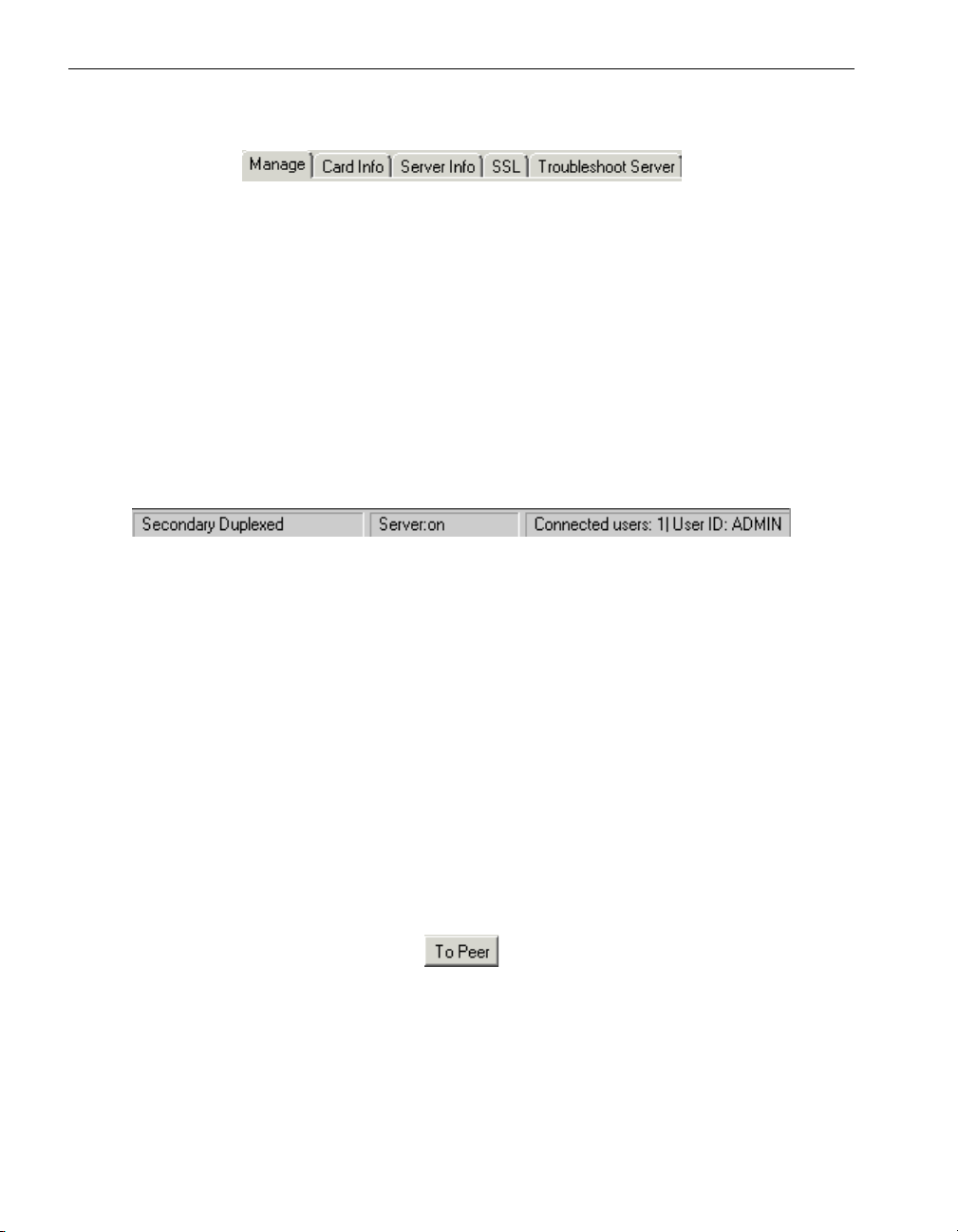
Parts of the VTM Console Interface
Figure 1-1. Tabs on the VTM Console
Status Bar
A status bar (see Figure 1-2) at the bottom of each Web page displays the following
connection information about the VTM and Express5800/320Ma system:
• VTM you are logged in to (Primary or Secondary) and whether one or both
VTMs are operating (Simplexed or Duplexed, respectively)
• Whether the server is powered on or off
• Number of users connected and ID of the users who are logged in
Figure 1-2. VTM Console Status Bar
The Manage page also displays a To Pe e r bu tt on , so that you can switch to the primary
VTM.
To Peer Button
At the time you connect to a VTM, it could be the primary or secondary VTM. You can
identify whether the VTM you are about to log on to is primary or secondary by looking
at the status bar, which displays either Primary or Secondary. For access to all the
features of the VTM console, log on to the primary VTM. The To Peer button, shown in
Figure 1-3, enables you to switch between the primary and secondary VTMs.
To switch to the other VTM, click To Peer before logging in to the VTM console.
Typically, you switch to the primary VTM so that you can use Advanced Video
Redirection (AVR) and remote storage.
Figure 1-3. To Peer Button
Related Topic
• “Description of the VTM Console Tabs”
1-4 Express5800/320Ma: Virtual Technician Module User’s Guide
Page 15

Description of the VTM Console Tabs
Each tab on the VTM console enables you to perform different tasks.
• “What You Can Do on the Manage Tab”
• “What You Can Do on the Card Info Tab”
• “What You Can Do on the Server Info Tab”
• “What You Can Do on the SSL Tab”
• “What You Can Do on the Troubleshoot Server Tab”
What You Can Do on the Manage Tab
Use the Manage tab on the primary VTM to configure and use Advanced Video
Redirection (AVR) and remote storage. AVR enables you to control the video,
keyboard, and mouse of the Express5800/320Ma system remotely. Remote storage
enables you to connect up to three storage devices or image files from a remote
management PC to the host system.
Use the Manage tab on the primary or secondary VTM to view the system event log,
view a snapshot of the last screen when an asynchronous server restart (ASR) event
occurs, reboot the operating system when it is not responding, or power the system on
and off.
Description of the VTM Console Tabs
To switch to the other VTM, click To Peer . Typically, you switch to the primary VTM so
that you can use Advanced Video Redirection (AVR) and remote storage.
Use the Manage tab to:
• Start and end an AVR session
• Configure remote storage
• View a snapshot of the last screen before an ASR event
• Power off the system or force a system shutdown
• Power on the system
• View the system event log
Introduction to VTMs and the VTM Console 1-5
Page 16

Description of the VTM Console Tabs
What You Can Do on the Card Info Tab
The Card Info tab displays network settings, connection status, VTM serial number,
software revision, and other information about the VTM.
Use the Card Info tab to:
• View VTM information
• View the status of the connection between the VTM and the system
• View the network settings
What You Can Do on the Server Info Tab
The Server Info tab displays information about the Express5800/320Ma system that
has been set on the host using the ftServer Management Console (ftSMC).
Use the Server Info tab to view the server configuration.
What You Can Do on the SSL Tab
The SSL tab enables you to generate and upload a Secure Socket Layer (SSL) server
certificate and certificate authority (CA) certificate to ensure secure transmission over
the Internet. You can also set the VTM console to connect through an SSL Web server
or a non-SSL Web server.
Use the SSL tab to:
• Set the VTM to allow a standard login
• Set the VTM to use an SSL login
• Request a signed server certificate
• Upload a signed server certificate
• View the server certificate
• Display an expiration notification
1-6 Express5800/320Ma: Virtual Technician Module User’s Guide
Page 17

Express5800/320Ma Documentation
What You Can Do on the Troubleshoot Server Tab
The Troubleshoot Server tab provides procedures to perform the following tasks:
• Work around problems that caused the system to fail to start.
• Attempt to revive the system when the operating system is no longer responding.
Each procedure represents progressively more severe methods for reviving the
system.
Use the Troubleshoot Server tab to:
• Restart the system with faulty hardware
• Restore the default BIOS setup options on the system
• Perform a non-maskable interrupt (NMI) on the system
• Perform a hard reset of the system
• Force a shut down of the system
Express5800/320Ma Documentation
See the site planning guide for your system for a list of documents pertaining to your
system.
Related Topics
• VTM Online Documentation
• VTM Console Help System
VTM Online Documentation
This document is available at the following locations:
• From the VTM console as a Help system
• In the Express5800/320Ma Help and Manuals folder on the system desktop, which
also contains all other documents for the specific model of Express5800/320Ma
system on which the Help system is installed
You can view the documents in the Help system or open them in PDF format for
viewing or printing.
• On the World Wide Web at:
http://support.necsam.com/servers/
Introduction to VTMs and the VTM Console 1-7
Page 18

Express5800/320Ma Documentation
VTM Console Help System
The online Help system for the VTM console provides this document in a format that
you can view online in a browser such as Microsoft Internet Explorer 5.x and
Netscape
To display the online Help from the VTM console, click Help.
Use the Contents tab to view a list of the topics in the Help. Use the Index tab to look
up keywords to find information. Use the Search tab to find information that contains a
specific word.
®
Navigator® 6.x, or later versions.
1-8 Express5800/320Ma: Virtual Technician Module User’s Guide
Page 19

Chapter 2
Connecting to a VTM Console
The following topics explain how to connect to the VTMs and the VTM console:
• “Prerequisites for Using the VTM Console”
• “Installing the JRE and Setting the Browser Options”
• “Overview of How to Use the VTM Console”
• “Connecting to a VTM Console Session”
• “Logging On to the VTM Console”
• “Logging Out of the VTM Console”
• “Troubleshooting Connections to a VTM”
Prerequisites for Using the VTM Console
Before using the VTM console, make sure that:
• You know the user ID and password for logging in to the VTM console. By default,
these are both set to ADMIN, but they can be changed in the ftServer Management
Console (ftSMC). For more information, see the online Help for ftSMC.
2-
• An ActiveService Network (ASN) account has been created to enable the NEC
Technical Support to diagnose Express5800/320Ma system problems remotely
through the VTM console. This account is listed in ftSMC as the SMM ASN Hub ID.
Access to the ASN requires a service contract with NEC Solutions (America), Inc.
or an authorized service representative, and is implemented across a modem or
over the Internet. For instructions in setting up your ASN account, see the
Express5800/320Ma ActiveService Network Configuration Guide.
• You have installed the Java™ 2 Runtime Environment (JRE) and set the browser
options.
Related Topics
• “Overview of How to Use the VTM Console”
• “Connecting to a VTM Console Session”
• “Logging On to the VTM Console”
Connecting to a VTM Console 2-1
Page 20
Installing the JRE and Setting the Browser Options
Installing the JRE and Setting the Browser Options
Before logging in to the VTM console, install the Java 2 Runtime Environment (JRE) on
the computer that will run the VTM console, and then set certain Internet browser
options.
NOTE
The JRE is installed by a remote installation of ftServer
management software from the Express5800/320Ma
ExpressBuilder CD (1 of 2).
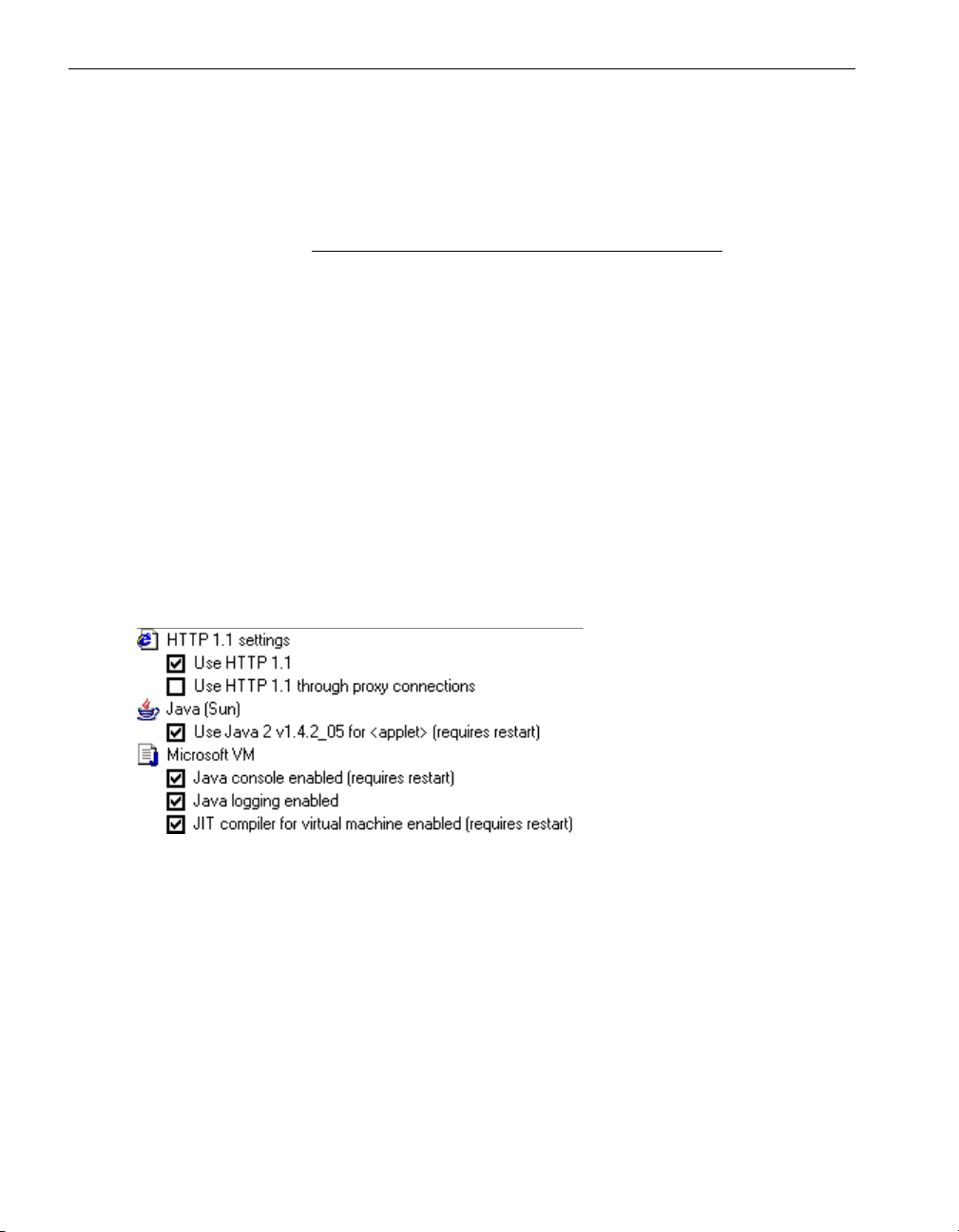
To install the JRE and set the browser options
1. In a Web browser, download and install the Java 2 Runtime Environment, Standard
Edition 1.4.2_05.
2. In your computer’s Control Panel, double-click Internet Options, and then click
the Advanced tab.
3. In the Internet Properties dialog box, select the check boxes as shown in
Figure 2-1.
Figure 2-1. Internet Options to Set for Using the VTM Console
4. Click OK to apply the settings. You must restart the system for these settings to
take effect.
Related Topic
• “Prerequisites for Using the VTM Console”
2-2 Express5800/320Ma: Virtual Technician Module User’s Guide
Page 21

Overview of How to Use the VTM Console
Overview of How to Use the VTM Console
1. Use a Web browser to connect to a VTM.
2. Take note of the status of the VTM you have connected to. If the status is
secondary, and if you want to use Advanced Video Redirection (AVR) or remote
storage, click To Peer on the login page. AVR and remote storage are available
only when you are logged in to the primary VTM.
3. Log on to the VTM console.
4. From the VTM console, view system configuration items, diagnose system
problems, and perform troubleshooting tasks.
5. When you finish, log off the VTM console.
Related Topics
• “Prerequisites for Using the VTM Console”
• “What You Can Do Using the VTM Console”
• “Connecting to a VTM Console Session”
Connecting to a VTM Console Session
You connect to the VTM console through a Web browser. If you use Microsoft Internet
Explorer and are unable to connect to a VTM console, ensure that the Internet Explorer
configuration is correct, as described in “Installing the JRE and Setting the Browser
Options” on page 2-2 and “Troubleshooting Connections to a VTM” on page 2-6.
Consider creating a Web page that contains a list of updated IP addresses for the
VTMs in your network. Providing this information on an accessible Web page enables
system administrators of Express5800/320Ma systems to more quickly connect to a
VTM and diagnose system problems.
NOTE
Connect to the primary VTM to access all the VTM
console functionality. Advanced Video Redirection and
remote storage are not available from the secondary
VTM.
Connecting to a VTM Console 2-3
Page 22

Logging On to the VTM Console
To connect to a VTM
1. Open a Web browser.
2. Enter the IP address of the primary or secondary VTM, and press Enter.
NOTE
The IP address of a VTM is displayed in ftServer
Management Console (ftSMC). In ftSMC, expand
ftServer (Local), ftServer I/O Enclosures, I/O
Enclosure - 10. Expand VTM Adapter - 3 or VTM
Adapter - 4. Click the nested instance of VTM
Adapter - 3 or VTM Adapter - 4 and view the value next
to IpAddress in the details pane.
3. When the Confirmation dialog box opens and asks if you want to accept the
Secure Socket Layer (SSL) server certificate, click Yes, No, or Always.
When the VTM console login window opens, you can log on to the VTM console.
Related Topics
• “Troubleshooting Connections to a VTM”
• “Prerequisites for Using the VTM Console”
• “Overview of How to Use the VTM Console”
• “Setting the VTM to Use SSL”
Logging On to the VTM Console
After connecting to the VTM, log on to the VTM console by entering a user ID and
password on the login page.
The VTM console has a default user name and password of ADMIN. To ensure
security, change the password on this account in the ftServer Management Console
(ftSMC).
CAUTION
!
If you have a service contract with NEC Solutions
(America), Inc. or an authorized service representative,
do not change the SMM ASN Hub ID or SMM ASN Hub
Password unless advised to do so by the NEC Technical
Support.
2-4 Express5800/320Ma: Virtual Technician Module User’s Guide
Page 23

Logging On to the VTM Console
An indicator in the bottom left of the login page shows whether you are logging in to the
primary VTM or secondary VTM. To log on to the peer VTM (the VTM not currently
displayed on the login page), click To Peer.
NOTE
Log on to the primary VTM to access all the VTM console
functionality. Advanced Video Redirection and mounting a
device on the host are not available from the secondary
VTM.
To log on to the VTM console
1. On the VTM login page, click Click here to login with SSL under the VTM
Homepage title to log on so that the VTM session uses a secure, encrypted
channel.
2. Next to User ID on the login page, type the user ID for the account.
3. Next to Password, type the password for the account.
4. Click Login.
NOTE
If you navigate to another Web site while the VTM session
is active, your VTM session ends and you must log on
again.
To log on to the Peer VTM
1. On the VTM login page, click To Peer.
2. In the User ID field on the login page, type your VTM user ID name.
3. In the Password field, type the password.
4. Click Login.
Related Topics
• “Connecting to a VTM Console Session”
• “Prerequisites for Using the VTM Console”
• “Overview of How to Use the VTM Console”
• “VTM System Operation and Configuration”
Connecting to a VTM Console 2-5
Page 24

Logging Out of the VTM Console
Logging Out of the VTM Console
To log off the VTM console, click Logout at the bottom of any page, and then click OK.
The VTM login page opens, where you can log on again when you are ready.
Although you are still connected to the VTM after logging out, authorized users can
access the Express5800/320Ma system by logging in to the VTM console if they supply
the correct user ID and password.
NOTE
If the VTM console is idle for 30 minutes or longer, you will
be automatically logged out and must log on again.
Related Topics
• “Logging On to the VTM Console”
• “Overview of How to Use the VTM Console”
Troubleshooting Connections to a VTM
The following settings in Microsoft Internet Explorer 5.0 and subsequent versions can
prevent you from connecting to the VTM:
• The security setting for Internet connections is set to High.
• The LAN settings in Internet Explorer are using a proxy server.
Problem: Security for Internet Is Set to High
Symptom. The following message displays: Your current security settings
prohibit ActiveX controls on the page. As a result, the page may
not display correctly.
Resolution. Reset the security setting for all Internet connections, or for the
connections to specific VTMs. If using a lower setting for all Internet connections is not
acceptable, reset the security setting for the VTMs to which you want to connect.
To reset the security setting for all Internet connections
1. On the Internet Explorer Too l s menu, click Internet Options.
2. Click the Security tab, and then click the Internet icon.
3. Under Security level for this zone, the security is displayed as High. Move the
slider down to the Medium position or lower, and click OK.
2-6 Express5800/320Ma: Virtual Technician Module User’s Guide
Page 25

Troubleshooting Connections to a VTM
To reset the security setting for specific VTMs
1. On the Internet Explorer Too l s menu, click Internet Options.
2. Click the Security tab.
3. Click the Local intranet icon, and then click Sites.
4. In the Local intranet dialog box, click Advanced.
5. In the additional Local intranet dialog box, type the IP address of each VTM next
to Add this Web site to the zone, and click Add. After entering all the VTMs to
which you want to connect, click OK twice to close both Local intranet dialog
boxes.
6. On the Security tab, under Security level for this zone, move the slider to the
Medium position or lower, and click OK.
Problem: LAN Settings in the Browser Are Using a Proxy Server
Symptom. A pop-up window warns: Internet Explorer could not open the
Internet site http://IP_address_of_Virtual_Technician_Module or
A connection with the server could not be established; or a page
displays the warning The page cannot be displayed.
Although other problems can cause this symptom, typically the cause is that the LAN
settings in Internet Explorer are using a proxy server.
Resolution. Specify settings to prevent Internet Explorer from using a proxy server to
connect to the VTMs.
To prevent Internet Explorer from using a proxy server to connect to the VTMs
1. On the Internet Explorer Too l s menu, click Internet Options.
2. Click the Connections tab, and then click LAN Settings.
3. If Use a proxy server is selected, do one of the following:
• If the IP addresses of the VTMs are recognized as local addresses and the
security settings on the proxy server permit, click Bypass proxy server for
local addresses. Click OK twice to close the Local Area Network (LAN)
Settings dialog box and the Internet Options dialog box.
• If the IP addresses of the VTMs are not recognized as local addresses, click
Advanced. Under Exceptions, type the IP addresses of the VTMs next to Do
not use proxy server for addresses beginning with. Click OK three times to
close the Proxy Settings, Local Area Network (LAN) Settings, and Internet
Options dialog boxes.
Connecting to a VTM Console 2-7
Page 26

Troubleshooting Connections to a VTM
2-8 Express5800/320Ma: Virtual Technician Module User’s Guide
Page 27

Chapter 3
Reviving a System That Is Not
The “When the System Fails to Start” on page 3-1 topic describes what you can do
when a fault-resilient boot has not successfully started the operating system.
The following topics explain how to use the VTM console to revive a system when the
operating system is no longer responding:
• “When the System Is No Longer Responding”
• “Powering On the System”
• “Viewing the System Configuration”
• “Viewing the System Event Log”
• “Understanding a State-Sensitive Recovery”
• “Understanding a Fault-Resilient Boot”
When the System Fails to Start
If your system fails to start, you can perform one or both of the following procedures:
Responding
3-
• Restart a system with faulty hardware
Perform this procedure to start the system, if possible, despite a CPU enclosure or
I/O enclosure that is only partially functional.
• Restore the default BIOS setup options
Restores the system BIOS Setup options to their default (factory) settings.
Reviving a System That Is Not Responding 3-1
Page 28

When the System Is No Longer Responding
Restoring the Default BIOS Setup Options
Restore the BIOS Setup options on a system to their default (factory) settings when the
system does not start with the current settings. The default settings are optimal settings
for the system.
To restore the default BIOS Setup options
1. On the Troubleshoot Server tab, make sure that power to the system is off. Click
Power off server to turn off power to the system.
2. Click Restore default BIOS settings to select it.
3. Optionally, select Normal, the default value, or Boot with faulty hardware. See
“Restarting a System with Faulty Hardware” for more information about the Boot
with faulty hardware option.
4. Click Power on Server.
5. In the Confirmation dialog box, click Ye s.
Restarting a System with Faulty Hardware
If your system fails to start because no fully functional pair of CPU and I/O elements is
present, you can force the system to start, if possible, using a CPU element or I/O
element that is only partially functional.
To restart a system with a partially functional CPU or I/O element
1. On the Troubleshoot Server tab, make sure that power to the system is off. Click
Power off server to turn off power to the system.
2. Click Boot with faulty hardware.
3. Click Power on Server.
4. In the Confirmation dialog box, click Ye s.
Related Topic
• “Restoring the Default BIOS Setup Options”
When the System Is No Longer Responding
When the operating system on an Express5800/320Ma system has been operational
but ceases to respond to user actions, the system controller automatically performs a
state-sensitive recovery (SSR) to try to restore the operating system. An SSR moves
through a set of progressively more severe steps to try to restore the system. See
“Understanding a State-Sensitive Recovery” on page 3-9 for more information about
SSR.
3-2 Express5800/320Ma: Virtual Technician Module User’s Guide
Page 29

If the system is still not responding after an SSR, or if the operating system has been
restored but another part of the system (for example, keyboard or mouse) is not
responding to the operating system, try the following procedures, which are listed in
order by ascending severity level:
• Perform a non-maskable interrupt from the Troubleshoot tab.
• Perform a hard reset from the Troubleshoot tab.
• Power off the system from the Manage tab.
• Force the system to power off from the Troubleshoot tab.
Related Topics
• “Viewing the System Event Log”
• “Powering On the System”
Performing a Non-Maskable Interrupt
If the Express5800/320Ma system is not responding, but the operating system is
running, perform a non-maskable interrupt (NMI) from the VTM console. An NMI saves
the contents of memory to a dump file, and then restarts the operating system.
Interrupts try to keep all CPUs synchronized while the system controller attempts to
resolve the problem.
When the System Is No Longer Responding
NOTE
If the operating system is not running, the NMI button is
unavailable and cannot be clicked. In this case, try
performing a hard reset.
If the NMI is successful, a message is displayed indicating that the operating system
has failed. The operating system is then restarted. If the NMI does not restore the
operating system, the system controller starts a state-sensitive system recovery, and
then starts a full fault-resilient boot if the SSR fails.
CAUTION
!
Before performing an NMI, make sure that no other
administrators are using the system.
If performing an NMI does not resolve the problem, see “When the System Is No
Longer Responding” for a list of other steps to try.
Reviving a System That Is Not Responding 3-3
Page 30

When the System Is No Longer Responding
To perform a non-maskable interrupt
1. On the VTM console, click the Troubleshoot Server tab, and then click NMI.
2. On the Confirmation dialog box, click OK.
Related Topics
• “When the System Is No Longer Responding”
• “Resetting the Operating System”
• “Powering Off the System from the Manage Tab”
• “Forcing the System to Power Off”
Resetting the Operating System
If the Express5800/320Ma system is not responding, and you have already performed
a non-maskable interrupt (NMI), try a hard reset from the VTM console. In this process,
the system controller does one of the following:
• If the operating system is running, the system controller performs a state-sensitive
recovery, except that it skips the NMI.
• If the operating system is not running, but standby power is available, the system
controller starts a full fault-resilient boot.
CAUTION
!
Before resetting the host system, make sure that no other
administrators are using the system.
If resetting the operating system does not resolve the problem, try powering off the
system.
To reset the operating system
1. On the VTM console, click the Troubleshoot Server tab, and then click Hard
Reset.
2. On the Confirmation dialog box, click OK.
Related Topics
• “When the System Is No Longer Responding”
• “Performing a Non-Maskable Interrupt”
• “Powering Off the System from the Manage Tab”
• “Forcing the System to Power Off”
3-4 Express5800/320Ma: Virtual Technician Module User’s Guide
Page 31

When the System Is No Longer Responding
Powering Off the System from the Manage Tab
You can click ftServer Power Button on the Manage tab of the VTM console to start
up and shut down the Express5800/320Ma system. When the system is booting or
running, a green indicator and the text Server Power is ON are displayed in the
Front Panel group box. Otherwise, Server Power is OFF is displayed, and the
indicator is gray.
Clicking ftServer Power Button works the same way as tapping the button on the front
panel of the system. The system responds in different ways, depending on the current
state of the operating system:
• If the operating system or the BIOS is starting, stopping, or running, click ftServer
Power Button to shut down the system, preventing the system from starting up.
• If the operating system hangs or a hardware failure occurs, click ftServer Power
Button to attempt to shut down the system. If the operating system is completely
hung, a graceful shutdown may not be possible, in which case the system controller
attempts a state-sensitive recovery (SSR).
• If the operating system is running normally, click ftServer Power Button to shut
down the operating system. You can change the behavior of the button while the
operating system is running in the Shutdown Event Tracker dialog box in
Windows, which is controlled by Group Policy settings. For instructions, see your
Windows documentation.
To turn off the system from the Manage tab
1. On the VTM console, click the Manage tab, and then click ftServer Power Button.
2. On the Confirmation dialog box, click OK.
Related Topics
• “When the System Is No Longer Responding”
• “Performing a Non-Maskable Interrupt”
• “Resetting the Operating System”
• “Forcing the System to Power Off”
Reviving a System That Is Not Responding 3-5
Page 32

Powering On the System
Forcing the System to Power Off
If the operating system stops responding, the system controller typically attempts a
state-sensitive recovery (SSR). However, you can force the system to shut down,
bypassing the SSR, by clicking ftServer Power Off on the Troubleshoot Server tab.
NOTE
Before forcibly shutting down the system, try performing a
non-maskable interrupt or a hard reset first.
Clicking ftServer Power Off works the same way as holding in the power button on the
front panel of the system for more than 4 seconds, shutting down the system.
CAUTION
!
Before removing power, make sure other administrators
are not using the system and that essential applications
do not become unavailable unexpectedly.
To force a system shutdown
1. Exit from any applications that are running.
2. On the VTM console, click the Troubleshoot Server tab, and then click ftServer
Power Off.
3. On the Confirmation dialog box, click OK.
Related Topics
• “When the System Is No Longer Responding”
• “Performing a Non-Maskable Interrupt”
• “Resetting the Operating System”
• “Powering Off the System from the Manage Tab”
Powering On the System
When standby power is on, you boot the Express5800/320Ma system by clicking either
ftServer Power Button on the Manage tab or ftServer Power On on the Troubleshoot
Server tab. These buttons work the same way as tapping the power button on the front
panel of the computer.
3-6 Express5800/320Ma: Virtual Technician Module User’s Guide
Page 33

Viewing the System Configuration
Before you boot the system, make sure that:
• AC power is being applied to the system.
• The monitor and any other peripheral devices are turned on.
For more information about operating the system hardware, refer to the operation and
maintenance guide for your system.
To boot the system from the Manage tab
1. On the VTM console, click the Manage tab.
2. In the Front Panel group box, click ftServer Power Button.
To boot the system from the Troubleshoot Server tab
1. On the VTM console, click the Troubleshoot Server tab.
2. Click ftServer Power On.
Related Topics
• “Powering Off the System from the Manage Tab”
• “Forcing the System to Power Off”
Viewing the System Configuration
To view the server settings, click the Server Info tab. Server settings are configured at
the host level and cannot be changed in the VTM console.
The fields on the Server Info page are:
• Name. Name of the server.
• IP Address. Server IP address.
• TimeZone. Time zone in which the server is located.
• POST Code. Last power-on self-test code (POST) received from the system
controller. For a list of POST codes, see Appendix A.
• Server State. Current state of the server.
• System LCD. Current state of the system.
Reviving a System That Is Not Responding 3-7
Page 34

Viewing the System Event Log
Viewing the System Event Log
The system event log is a list of recorded Express5800/320Ma system and VTM events
that you can view on the VTM console to diagnose system problems. See Figure 3-1
for an illustration of the system event log as displayed in the VTM console. Both the
primary and secondary VTMs and the primary and secondary system controllers send
messages to the primary VTM, where they are logged.
You can read system event log entries using the VTM console when the host system
is either running or shut down. You can also read the system event log entries from the
application log on the host. The primary VTM maintains its own system event log,
whereas the secondary VTM does not have a system event log unless it becomes the
primary VTM.
Figure 3-1. System Event Log
To view the system event log
1. On the VTM console, click the Manage tab, and then click View SEL.
2. To clear all of the entries in the log, click Clear.
3. When you finish viewing the entries, click Close.
Related Topic
• “When the System Is No Longer Responding”
3-8 Express5800/320Ma: Virtual Technician Module User’s Guide
Page 35

Understanding a State-Sensitive Recovery
Understanding a State-Sensitive Recovery
If the Express5800/320Ma system stops responding, the system controller
automatically starts a state-sensitive recovery (SSR). An SSR tries to isolate a CPU to
preserve the state of the system and to create dump information that can be used to
diagnose the problem.
In an SSR, the system controller performs three procedures that move through
progressively more-severe recovery levels. After each procedure, the system controller
waits to receive a heartbeat, or message, from the host system before trying a more
invasive procedure.
The system controller logs the system failure in the system event log, and then tries
each of the following, in order, until the system is restored to normal operation:
1. Initiates a non-maskable interrupt (NMI) to try to avoid rebooting the system, to
save the contents of system memory to a dump file, and to restart the operating
system.
2. Issues a hard reset, which changes the system state to “crashed,” and isolates the
CPU whose state it wants to preserve. The system controller then tries to reboot
the system, while keeping the specified CPU isolated and in a broken state.
3. Performs a full fault-resilient boot (FRB), which takes both CPUs offline and tries to
boot the system. Dump information is lost during this process.
For information about how to retrieve dump files, see the Express5800/320Ma: System
Administrator’s Guide or the online Help for ftServer Management Console (ftSMC).
Related Topics
• “Understanding a Fault-Resilient Boot”
• “When the System Is No Longer Responding”
Understanding a Fault-Resilient Boot
In a fault-resilient boot (FRB), the system controller makes up to six consecutive
attempts to start the Express5800/320Ma system. Each attempt involves restarting
CPU and I/O elements in a fixed order. This configuration is used when you start a
system that has been powered off; it is not used when you simply restart the operating
system.
The system controller tries each boot configuration in the list only once, and does not
repeat the boot process if all of the configurations fail. If one of the boot configurations
is successful, the FRB process stops and the system controller stops trying to restart
CPU or I/O elements. The operating system is responsible for bringing any additional
hardware into operation, including, if possible, the other CPU and I/O elements.
Reviving a System That Is Not Responding 3-9
Page 36

Understanding a Fault-Resilient Boot
Because an FRB powers off CPU and I/O elements to restore the system, dump files
cannot be recovered to diagnose the reason for the system problem.
Related Topics
• “Understanding a State-Sensitive Recovery”
• “When the System Is No Longer Responding”
3-10 Express5800/320Ma: Virtual Technician Module User’s Guide
Page 37

Chapter 4
The following topics explain how to configure and use Advanced Video Redirection
(AVR):
• “Using Advanced Video Redirection”
• “Managing AVR Sessions”
• “Configuring and Connecting Remote Storage Devices”
• “Viewing a Snapshot of the Last Screen Before an ASR Event”
Using Advanced Video Redirection
Advanced Video Redirection (AVR) enables you to control the keyboard, video, and
mouse (KVM) of an Express5800/320Ma system remotely from a VTM console. The
system’s video is redirected to the client computer running the VTM console, and the
client computer’s mouse and keyboard are redirected to the server. The mouse and
keyboard connect to the system over an internal USB bus, and the video connects to
the system over an internal VGA bus. AVR is available only when you are logged in to
the primary Virtual Technician Module (VTM).
Using AVR
4-
Multiple users can each run AVR and other remote desktop sessions simultaneously,
resulting in competition for control of the Windows desktop. For example, you can log
on to the VTM over your local area network (LAN) while NEC Technical Support or
other authorized service representative dials in, and you can each have your own AVR
sessions open.
The following topics explain how to start and end an AVR session:
• “Starting and Ending an AVR Session”
• “Logging On to the Host from an AVR Session”
Using AVR 4-1
Page 38

Using Advanced Video Redirection
Starting and Ending an AVR Session
If you start an Advanced Video Redirection (AVR) session and you are inactive for a
period of time, or if the Express5800/320Ma system shuts down, the AVR session
ends.
To start an AVR session
1. On the VTM console, click the Manage tab, and then click Advanced Video
Redirection.
2. Using the keyboard and mouse, diagnose the system as needed.
3. To exit from the AVR session, click the Close button at the top-right of the
Advanced Video Redirection window. Allow several seconds for the window to
close.
Options on the main AVR window allow you to send special key sequences during the
AVR session.
The Sync Mouse option is not supported at this time.
Related Topics
• “Logging On to the Host from an AVR Session”
• “Sending Special Key Sequences in an AVR Session”
• “Managing AVR Sessions”
Logging On to the Host from an AVR Session
If no one is logged on to the host system when you start an Advanced Video
Redirection (AVR) session, a message instructs you to log on.
To log on to the host from an AVR session
1. After you start an AVR session, click Ctrl-Alt-Del at the bottom of the AVR window.
2. On the login window, type your user ID and password, and click Login.
Related Topics
• “Starting and Ending an AVR Session”
• “Managing AVR Sessions”
4-2 Express5800/320Ma: Virtual Technician Module User’s Guide
Page 39

Managing AVR Sessions
The menus on the Advanced Video Redirection window control the way data is
captured on the monitor of the Express5800/320Ma system during an Advanced Video
Redirection (AVR) session. See the following for descriptions of the tasks that you can
perform using these menus:
• “Setting Monitor Controls in an AVR Session”
• “Setting Video Capture Parameters in an AVR Session”
• “Setting Languages for an AVR Session”
• “Setting AVR to Use Typing Mode”
• “Using the Virtual Keyboard”
• “Sending Special Key Sequences in an AVR Session”
• “Using SSL for Keyboard Entries in an AVR Session”
• “Restoring Mouse Behavior”
• “Hiding the Client Computer’s Cursor in an AVR Session”
• “Using AVR in View-Only Mode”
• “Troubleshooting AVR Sessions”
Managing AVR Sessions
Setting Monitor Controls in an AVR Session
In an Advanced Video Redirection (AVR) session, you can change the brightness,
sharpness, contrast, and other settings to control the appearance of the AVR monitor
simulation.
To set the monitor controls
1. Click Settings, point to Display, and click Monitor Controls.
2. Specify the following information:
• Next to Position X and Position Y, move the scroll bar to shift the monitor
output horizontally and vertically. To let the system select the best value to use
in both fields, click Auto-position. If you select Auto-position, the changes take
place immediately.
• Next to Sharpness, move the scroll bar to specify the desired sharpness. To
let the system select the best value to use, click Auto-sharpness. If you select
Auto-sharpness, the changes take place immediately.
• Next to Brightness, move the scroll bar to specify the desired brightness.
• Next to Contrast, move the scroll bar to specify the desired contrast.
Using AVR 4-3
Page 40

Managing AVR Sessions
3. To set the brightness and contrast for the three Red/Green/Blue (RGB) color
components separately, click Fine Tuning, and type values in the additional fields
that appear. Or, use the scroll bar to set the RGB components.
4. Do one of the following:
• To apply the settings for only this AVR session, click Apply and then click
Close.
• To use these settings for subsequent AVR sessions until you change them
again, click Save and then click Close.
NOTE
To return to the default AVR monitor settings, select
Defaults on the AVR Monitor Control Settings dialog
box, and then click Close.
Related Topics
• “Setting Video Capture Parameters in an AVR Session”
• “Managing AVR Sessions”
Setting Video Capture Parameters in an AVR Session
In an Advanced Video Redirection (AVR) session, you can control how the video data
is captured for the simulation.
To set the video capture parameters
1. Click Settings, point to Display, and click Video Capture Parameters.
2. In the Frame Rate (screen/sec) field, specify how often frames are sent to the
computer running the AVR session. The higher the value, the more often screens
are sent. The default value of zero (0) sends frames at the highest possible rate.
3. In the Compression field, select the type of compression (compression mode) to
use for the video data. Use the information in Ta bl e 4 -1 to select a mode based on
the bandwidth between your system and the Virtual Technician Modules (VTMs),
and the performance and image quality you require. The default value is Fast
compression 1.
NOTE
If you are using any compression scheme, do not rely on
colors for information. For example, in ftServer
Management Console (ftSMC), icons may appear
dimmed instead of bright yellow.
4-4 Express5800/320Ma: Virtual Technician Module User’s Guide
Page 41

Managing AVR Sessions
Table 4-1. Selecting Compression Modes for AVR Sessions
Mode Performance Bandwidth Image Quality
No compression Lowest Highest Highest
Fast compression1 Fastest Medium Lowest
Fast compression2 Fast Lowest Lowest
Good quality Compression1 Medium Low Medium
Best quality compression1 Medium Medium Good
Best quality compression2 Low Low Good
4. In the Noise Sensitivity field, specify a value to determine whether a frame should
be updated, based on changes detected in the frame. Specify a high value to
enable the VTM to detect noise more easily, which results in a frame update. A low
value in the field makes the VTM less able to detect frame changes that result from
user interactions such as mouse movements. Valid values are from 0 to 3000. The
default and optimal value is 1000 to provide the sharpest image.
5. In the Tile Auto Update Period (ms) field, specify the maximum amount of time to
allow (in milliseconds) between frame updates, regardless of whether the frame
content has changed. The default value is 5000. Setting the value to 0 indicates you
want the frame to update only when the frame content has changed.
6. Do one of the following:
• To apply the settings for only this AVR session, click Apply and then click
Close.
• To use these settings for subsequent AVR sessions until you change them
again, click Save and then click Close.
NOTE
To return to the default AVR video parameters, select
Defaults on the AVR Video Capture Settings dialog box,
and then click Close.
Related Topics
• “Setting Monitor Controls in an AVR Session”
• “Managing AVR Sessions”
Using AVR 4-5
Page 42

Managing AVR Sessions
Setting Languages for an AVR Session
For Advanced Video Redirection (AVR) to work properly, specify the languages used
on the Express5800/320Ma system and the client computer running the VTM console.
To set languages on the server and client computer
1. Click Settings, and then click Languages.
2. Under Client, select the language being used on the computer running the VTM
console.
3. Under Remote, select the language being used on the server.
4. Click OK.
Related Topics
• “Setting AVR to Use Typing Mode”
• “Managing AVR Sessions”
Setting AVR to Use Typing Mode
The Typing Mode menu option ensures that the Express5800/320Ma system correctly
recognizes keys that you press during an Advanced Video Redirection (AVR) session.
Typically, when you press a key on your keyboard, both the actions of pressing the key
and releasing the key are sent separately over the Internet. Since the time between
these actions is dependent on the network, keys can sometimes be erroneously
repeated in AVR if a key stays pressed longer than the character repeat rate, which is
set in the Control Panel for the server’s keyboard.
To set AVR to use Typing Mode
• Click Settings, point to Keyboard, and click Typing Mode.
A check mark next to AVR Typing Mode indicates that pressed and released keys
are sent over the Internet as a pair to ensure that keys are not repeated.
Related Topics
• “Sending Special Key Sequences in an AVR Session”
• “Using the Virtual Keyboard”
• “Managing AVR Sessions”
4-6 Express5800/320Ma: Virtual Technician Module User’s Guide
Page 43

Using the Virtual Keyboard
In an Advanced Video Redirection (AVR) session, you can use a virtual keyboard
instead of typing on your own keyboard. The virtual keyboard is useful, for example, if
your computer keyboard is designed for another language and does not have all the
keys that are on the keyboard directly attached to the Express5800/320Ma system.
The virtual keyboard is based on the language used by the remote computer (the
server) and specified for the AVR session in the Language Selection dialog box.
To use the virtual keyboard in an AVR session
• Click Settings, point to Keyboard, and click Show Virtual Keyboard.
Related Topics
• “Setting Languages for an AVR Session”
• “Managing AVR Sessions”
Sending Special Key Sequences in an AVR Session
In an Advanced Video Redirection (AVR) session, most keys that you press transfer to
the Express5800/320Ma system correctly. Special key sequences that include keys
such as Alt, Ctrl, and Shift (for example, Alt+F4) do not transfer to the system properly
through a browser. AVR provides mechanisms for correctly transferring these special
key sequences:
Managing AVR Sessions
• Sending a single special key sequence. Requires you to click a button each time
before sending the special key.
• The Sticky Key option. The system recognizes special keys until you turn off the
option.
The LEDs at the bottom right of the AVR window indicate the current status of the Alt
key (left LED), Ctrl key (middle LED), and Shift key (right LED). The LED states are:
• Green. The key has not been pressed
• Yellow. The key has been pressed once
• Red. The key has been pressed two or more times
• Gray. Sticky Key mode is disabled
Using AVR 4-7
Page 44

Managing AVR Sessions
To send a single special key sequence
1. On the AVR window, select one of the following to send a key sequence that
contains that key: Ctrl, Alt, or Shift.
2. On your keyboard, press the key that represents the latter part of the key sequence
you want to send.
For example, to send the Alt+F4 key sequence, click Alt on the AVR window, and then
press F4 on your keyboard.
To set AVR to remember special key sequences
• Click Settings, point to Keyboard, and click Sticky Key Mode.
A check mark next to Sticky Key Mode indicates that each Alt, Ctrl, and Shift key
will be sent in combination with the next pressed key.
For example, to send Alt+F4, enable Sticky Key Mode, and then press Alt and F4
simultaneously.
Related Topic
• “Managing AVR Sessions”
Using SSL for Keyboard Entries in an AVR Session
You can use a Secure Socket Layer (SSL) connection to send keyboard strokes during
an Advanced Video Redirection (AVR) session.
To send keyboard strokes over an SSL connection
• Click Settings, point to Keyboard, and click Secure Keyboard.
A check mark next to Secure Keyboard indicates that SSL will be used to send
keyboard strokes to the server.
Related Topics
• Chapter 6, “Configuring SSL for VTM Access”
• “Managing AVR Sessions”
Restoring Mouse Behavior
If your mouse is not functioning properly in an Advanced Video Redirection (AVR)
session, you can restore the mouse to proper functioning by having it use the mouse
settings from the host.
4-8 Express5800/320Ma: Virtual Technician Module User’s Guide
Page 45

To restore mouse behavior
1. In an AVR session, click Settings.
2. Point to Mouse and then click Read Mouse Acceleration.
Related Topics
• “Hiding the Client Computer’s Cursor in an AVR Session”
• “Managing AVR Sessions”
Hiding the Client Computer’s Cursor in an AVR Session
In an Advanced Video Redirection (AVR) session, the cursors of both the client
computer (a crosshair) and the Express5800/320Ma system are displayed by default.
To hide or show the client computer’s cursor
• Click Settings, point to Mouse, and click Show Client Cursor. Repeat the process
to turn the cursor back on again.
A check mark next to Show Client Cursor indicates that the cursor of the client
(local) computer will be shown.
Managing AVR Sessions
Related Topics
• “Restoring Mouse Behavior”
• “Managing AVR Sessions”
Using AVR in View-Only Mode
Although Advanced Video Redirection (AVR) sessions are typically used to enter data
on the Express5800/320Ma system using the remote keyboard, you can set the
session to prevent keyboard entry and to allow only viewing of the server’s desktop
from the VTM console.
To enable or disable View-Only mode
• Click Settings, and then click View-Only Mode.
A check mark next to View-Only Mode indicates that no data can be written to the
server.
Related Topics
• “Managing AVR Sessions”
• “Troubleshooting AVR Sessions”
Using AVR 4-9
Page 46

Configuring and Connecting Remote Storage Devices
Troubleshooting AVR Sessions
If the keyboard does not work in an Advanced Video Redirection (AVR) session, click
in the AVR window. If the keyboard still does not work, click the Settings menu, and
ensure that View-Only Mode is not selected.
Related Topics
• “Using AVR in View-Only Mode”
• “Starting and Ending an AVR Session”
• “Managing AVR Sessions”
Configuring and Connecting Remote Storage Devices
In a VTM console session, you can mount on the host system a storage device that is
connected to your local computer. You can use this storage device to install, copy, or
move files to and from the Express5800/320Ma system.
You can mount up to three different storage devices on the system simultaneously. The
device can be a floppy disk drive, a CD-ROM drive, or an ISO image file. The device
appears at the server's USB port when the operating system is loaded. ISO image files
must reside on the client PC.
The iSCSI server that is built into the VTM console provides images of hard disks,
floppy disks, or CD-ROM drives, and emulates these devices.
To mount remote storage devices
1. Configure one of the following local devices so that you can connect it to the host
system:
• CD-ROM or floppy disk drive
• ISO image file
2. Connect the device to the Express5800/320Ma system.
Related Topics
• “Configuring a CD-ROM or Floppy Disk Drive as a Remote Storage Device”
• “Configuring a Local ISO Image File as a Remote Storage Device”
• “Connecting a Configured Local Storage Device to the Host”
4-10 Express5800/320Ma: Virtual Technician Module User’s Guide
Page 47

Configuring and Connecting Remote Storage Devices
Configuring a CD-ROM or Floppy Disk Drive as a Remote Storage Device
This procedure explains how to configure a local CD-ROM or floppy disk device as a
remote storage device that you can mount on the Express5800/320Ma system. See
“Configuring and Connecting Remote Storage Devices” on page 4-10 for general
information about configuring devices to mount on the host.
NOTE
Configuring the device is different from connecting it to the
host. See “Connecting a Configured Local Storage Device
to the Host” on page 4-13 for instructions on connecting a
configured device.
Once configured, a device remains in the list of configured devices until the VTM
console session ends or until you click Request iSCSI Logout or Force iSCSI Logout.
To configure a CD-ROM or floppy disk as a remote storage device
1. Click the Manage tab, and then click Remote Storage.
NOTE
You can click Remote Storage only if you are logged in to
the primary Virtual Technician Module (VTM).
2. In the Remote Storage Settings dialog box, select the iSCSI slot you want to
configure (0, 1, or 2).
3. Click LocalMedia Login, and then click Ye s or No to indicate whether to include
CD-ROMs in the search for devices to mount. Clicking No may result in a faster
search. If you search for subsequent devices to configure, the message asking if
you want to search for CD-ROMs does not appear.
4. In the iSCSI Server Target Configuration dialog box, select the device to be
mounted, and click Next.
5. If you selected a floppy drive in the previous step, and you want to prevent data
from being saved to the floppy disk, click readonly to select it, and click OK.
NOTE
When the connection established successfully
message is displayed, the search is complete, even
though the progress bar still appears to be searching.
6. Click OK to return to the Remote Storage Settings dialog box.
7. Connect the device to the host.
Using AVR 4-11
Page 48

Configuring and Connecting Remote Storage Devices
Related Topics
• “Configuring a Local ISO Image File as a Remote Storage Device”
• “Opening a Configured Device”
• “Connecting a Configured Local Storage Device to the Host”
Configuring a Local ISO Image File as a Remote Storage Device
This procedure explains how to configure an ISO image file as a remote storage device
that you can mount on the Express5800/320Ma system.
NOTE
Configuring the image file is different from connecting it to
the host. See “Connecting a Configured Local Storage
Device to the Host” on page 4-13 for instructions on
connecting a configured device.
When configured, an image file remains in the list of configured devices until the VTM
console session ends or until you click Request iSCSI Logout or Force iSCSI Logout.
To configure an image file as a remote storage device
1. Click the Manage tab, and then click Remote Storage.
NOTE
You can click Remote Storage only if you are logged on to
the primary Virtual Technician Module (VTM).
2. In the Remote Storage Settings dialog box, select the iSCSI slot you want to
configure (0, 1, or 2).
3. Click LocalMedia Login, and then click No if you are prompted to search for
CD-ROMs. If you already configured a device or image in this VTM console
session, the message asking if you want to search for CD-ROMs does not appear.
4. In the iSCSI Server Target Configuration dialog box, select New Image, and click
Next.
5. In the add LocalMedia - Connection dialog box, type a text identifier or name for
the image, and click OK.
6. Under Select Image/Devicefile from Filesystem, double-click the folder in which
the image file resides. The files and folders within the folder you double-clicked are
displayed.
If you select a folder in error, click refresh directory structure to display the
high-level folders again.
4-12 Express5800/320Ma: Virtual Technician Module User’s Guide
Page 49

Configuring and Connecting Remote Storage Devices
7. Under Select Image/Devicefile from Filesystem, select the file to be mounted on
the host.
8. Under logical type of Image/Devicefile, select the type of media from which the
image file was created. If the image file was created from a CD-ROM, select
CDROM. If the file was created from data on a hard drive, select Blockdevice.
9. Select or clear the following, as applicable, and click OK:
• To prevent the image file from being changed, click readonly to select it.
• If the image file is a removable device, click removable to select it.
NOTE
When the connection established successfully
message is displayed, the search is complete, even
though the progress bar still appears to be searching.
10. Click OK to return to the Remote Storage Settings dialog box.
11. Connect the device to the host.
Related Topics
• “Opening a Configured Device”
• “Connecting a Configured Local Storage Device to the Host”
Connecting a Configured Local Storage Device to the Host
Use this procedure to connect the configured local devices or images to the
Express5800/320Ma system. Since the connection process connects all the local
devices and images that have been configured, ensure that you configure all the
devices or images at one time before connecting.
NOTE
To disconnect or change to a different device or image
after connecting, you must disconnect the device from the
server.
To connect the configured remote storage device to the host
1. In the Remote Storage Settings dialog box, select an iSCSI slot that contains a
configured device or image (all configured devices are connected at once,
regardless of the one selected).
2. Click Connect to Host I/F to select it.
Using AVR 4-13
Page 50

Configuring and Connecting Remote Storage Devices
3. If a System Settings Change message appears, indicating that the operating
system has finished installing new devices and asking if you want to restart the
computer, click No. You do not need to restart the computer.
4. When a message in the main AVR window indicates that a high-speed USB device
is plugged into a non-high-speed USB hub, ignore the message and close it.
The connected device is available on the server as a floppy disk drive or CD drive.
Related Topics
• “Configuring and Connecting Remote Storage Devices”
• “Disconnecting a Device from the Host”
Disconnecting a Device from the Host
Use the following procedure to disconnect a local device from the Express5800/320Ma
system.
CAUTION
!
Failure to use this procedure can cause unpredictable
results in the operating system.
To disconnect the device from the host
1. Start an Advanced Video Redirection (AVR) session to display and control the
server.
2. In AVR, on the server’s taskbar at the bottom of the window, double-click the Safely
Remove Hardware icon (keyboard with green arrow) .
The Safely Remove Hardware dialog box opens.
3. In the Hardware devices box, select USB Mass Storage Device and click Stop.
4. On the Stop a Hardware device dialog box, select USB Mass Storage Device
and click OK.
5. If you connected multiple devices, repeat steps 3 and 4 for each configured device;
otherwise, go to step 6.
6. On the Safely Remove Hardware dialog box, click Close.
7. In the VTM console on the Remote Storage Settings dialog box, clear the
Connect to Host I/F check box. A message warns you that data corruption can
result if data transfers are occurring.
8. Click OK. The device is safely disconnected from the host.
4-14 Express5800/320Ma: Virtual Technician Module User’s Guide
Page 51

9. When a message in the main AVR window indicates that a high-speed USB device
is plugged into a non-high-speed USB hub, ignore the message and close it.
10. Close the Remote Storage Settings dialog box and, optionally, the AVR session.
The device continues to be listed as an iSCSI session until you remove the device from
the list of configured iSCSI sessions.
Related Topics
• “Configuring a CD-ROM or Floppy Disk Drive as a Remote Storage Device”
• “Configuring a Local ISO Image File as a Remote Storage Device”
• “Removing a Configured Device”
• “Connecting a Configured Local Storage Device to the Host”
Removing a Configured Device
You can remove a device from the list of configured iSCSI sessions. You might need
to do this, for example, to free up a session for another device.
To remove a configured device
1. In the Remote Settings dialog box, click to select the device that you want to
remove.
2. Under Slot Management, click Request iSCSI Logout.
3. When a message asks if you are sure you want to close the connection, click OK.
Configuring and Connecting Remote Storage Devices
The device continues to be configured for the duration of the VTM console session, and
you can open the connection again (connect it to an iSCSI session).
Opening a Configured Device
You can open a connection again if you need to reconnect it to the
Express5800/320Ma system. Opening a connection assigns a previously configured
device to an available iSCSI session.
To open a configured device
1. In the Remote Settings dialog box, select an iSCSI session.
2. Under Slot Management, click LocalMedia Login.
3. Select the device and click Next.
4. Select or clear the following, as applicable, and click OK:
• To prevent the image file from being changed, click readonly to select it.
• If the image file is a removable device, click removable to select it.
Using AVR 4-15
Page 52

Viewing a Snapshot of the Last Screen Before an ASR Event
NOTE
When the connection established successfully
message is displayed, the search is complete, even
though the progress bar still appears to be searching.
5. Connect the device to the host.
The iSCSI Server Target Configuration Dialog Box
In the iSCSI Server Target Configuration dialog box, select a device to mount, and
click Next. If you select a CD-ROM or floppy drive, make sure a disk is in the drive.
To configure a CD-ROM or floppy drive as a remote storage device, see step 4 and
following in “Configuring a CD-ROM or Floppy Disk Drive as a Remote Storage Device”
on page 4-11.
To configure an ISO image file as a remote storage device, see step 4 and following in
“Configuring a Local ISO Image File as a Remote Storage Device” on page 4-12.
Viewing a Snapshot of the Last Screen Before an ASR Event
The Virtual Technician Module (VTM) is configured to take a snapshot of the screen
when an asynchronous server restart (ASR) event occurs (for example, the blue screen
in Windows). The screen snapshot appears in your browser, and helps to identify the
reasons for the server crash.
The ASR snapshot is stored in the VTM's volatile memory and contains the time and
date the snapshot was taken. If no ASR event has occurred since the VTM was last
turned on, the message No ASR Screen Available is displayed.
To view a snapshot at an ASR event
• Click the Manage tab, and then click ASR Screenshot.
Related Topic
• “When the System Is No Longer Responding”
4-16 Express5800/320Ma: Virtual Technician Module User’s Guide
Page 53

Chapter 5
The Card Info tab on the VTM console displays VTM configuration information. The
following topics explain how to perform tasks from the Card Info tab:
• “Viewing VTM Information”
• “Viewing the Status of the Connection to the System”
• “Viewing the Network Settings”
• “Rebooting the VTM”
Viewing VTM Information
Click the Card Info tab and look in the Card Info group box to view the following types
of information about the VTM:
Part Number. Part number of the VTM card. Use this number to request a replacement
card.
I/O Chassis Slot. Slot number in which the VTM card is installed. The first number,
which is either 10 or 11, indicates which I/O element contains the card you logged into.
Viewing the VTM Configuration
5-
Serial Number. Serial number of the VTM card.
Software Revision. Software revision on the card, which you can use to check if newer
revisions are available.
Firmware Revision. Current version of the firmware, which can be used to check if
newer revisions are available.
Core Version. Core version of the firmware.
Viewing the VTM Configuration 5-1
Page 54

Viewing the Status of the Connection to the System
Viewing the Status of the Connection to the System
To view the status of the connection from the VTM to the system, click the Card Info
tab, and look in the Connector Status group box. The status is displayed as either
connected or not connected.
Related Topics
• “When the System Is No Longer Responding”
• “Viewing the System Event Log”
Viewing the Network Settings
Network settings comprise information about network connections for the VTM.
Network connections are configured in the ftServer Management Console (ftSMC). For
configuration instructions, see the online Help for ftSMC.
To view network settings
1. Click the Card Info tab.
In the Network group box, the MAC address assigned to the VTM port is displayed
next to Ethernet Address.
2. In the Network group box, click Network Settings.
The fields in the Ethernet group box are:
• IP Address. IP address for the LAN connection to the VTM.
• Netmask. Subnet mask number for the LAN.
• Gateway IP. Gateway IP address for the LAN.
• Use DHCP. Check box indicating whether IP addresses are obtained from a
DHCP server. If the check box is not checked, static IP addresses are
assigned.
The fields in the PPP group box are:
• IP Address. IP address used for the PPP connection between the
Express5800/320Ma system and the VTM.
• Netmask. Subnet mask number for the PPP connection.
3. When you finish viewing the settings, click Close.
Related Topic
• “VTM System Operation and Configuration”
5-2 Express5800/320Ma: Virtual Technician Module User’s Guide
Page 55

Rebooting the VTM
Reboot the Virtual Technician Module (VTM) after you upload a new SSL certificate.
To reboot the VTM
1. Click the Card Info tab, and then click Reboot VTM.
2. On the Confirmation dialog box, click OK.
You are logged out of the VTM console and returned to the login page, where you
can log on again.
Rebooting the VTM
Viewing the VTM Configuration 5-3
Page 56

Rebooting the VTM
5-4 Express5800/320Ma: Virtual Technician Module User’s Guide
Page 57

Chapter 6
Secure Socket Layer (SSL) is a transmission protocol that secures customer message
transmissions and access to the Virtual Technician Module (VTM). The following topics
explain how to set the VTM to use either an SSL or non-SSL connection:
• “Overview of SSL”
• “Setting the VTM to Use a Standard Login”
• “Setting the VTM to Use SSL”
• “Requesting a Signed Server Certificate”
• “Uploading a Signed Server Certificate”
• “Viewing the Server Certificate”
• “Configuring an Expiration Notification”
Overview of SSL
The Secure Socket Layer (SSL) transmission protocol provides secure access to the
Virtual Technician Module (VTM) by encrypting data sent between the VTM and the
VTM console session and requiring server authentication. To use SSL encryption and
server authentication for a VTM console session, a server certificate and a certificate
authority (CA) certificate are required to authenticate the transmission.
Configuring SSL for VTM Access
6-
Related Topics
• “Setting the VTM to Use a Standard Login”
• “Setting the VTM to Use SSL”
• “Requesting a Signed Server Certificate”
• “Uploading a Signed Server Certificate”
Setting the VTM to Use a Standard Login
By default, users log on to the VTM console using standard login, in which data sent
between you and the Express5800/320Ma system is not encrypted.
Configuring SSL for VTM Access 6-1
Page 58

Setting the VTM to Use SSL
To set up VTMs to enable a standard login
1. Click the SSL tab.
2. Clear the Secured Web Access (SSL) check box.
3. Click Apply.
A check mark next to Secured Web Access (SSL) indicates that secure connections
can be made to the VTM console.
Related Topics
• “Setting the VTM to Use SSL”
Setting the VTM to Use SSL
Before you set up the Virtual Technician Module (VTM) to enable or require the use of
SSL during VTM console sessions, ensure that the following conditions have been met:
• The server certificate is valid.
• All users have a certificate authority (CA) certificate from the same CA that issues
the VTM server certificate.
CAUTION
!
You must complete the above items before selecting the
Secured Web Access (SSL) check box on the SSL page;
otherwise, you cannot log on to the VTM.
To set the VTM to enable an SSL connection
1. Click the SSL tab.
2. Request a signed server certificate.
3. Upload the signed server certificate to the VTM console.
4. To use SSL to encrypt data sent to and from the server during VTM console
sessions, select Secured Web Access (SSL).
5. If you installed a client certificate from your selected CA, and you have a CA
certificate from the same CA on your browser, select Enforce Client Certificate,
in the Certificate Authority Certificate group box, to force administrators of the
Express5800/320Ma system to use this certificate when they connect to the VTM.
6-2 Express5800/320Ma: Virtual Technician Module User’s Guide
Page 59

Requesting a Signed Server Certificate
6. To enable users with a valid certificate installed on their browsers to connect to the
VTM console automatically, select Auto log-on.
NOTE
Auto log-on is enabled only if you select Enforce Client
Certificate.
7. Next to Symmetric Encryption Strength (bit), select the number of bits for the
encryption strength.
8. To save the entry, click Apply.
9. Click the Card Info tab and click Reboot VTM. For instructions on rebooting the
VTM, see “Rebooting the VTM”.
Related Topics
• “Overview of SSL”
• “Logging On to the VTM Console”
• “Requesting a Signed Server Certificate”
• “Uploading a Signed Server Certificate”
Requesting a Signed Server Certificate
Request a signed server certificate if your server certificate is expiring, or if you want
to use your own certificate instead of the default one that NEC Solutions (America), Inc.
provides. After requesting a signed certificate, you must upload it.
To request a signed server certificate
1. Click the SSL tab to open the SSL page, and then click Request Generation.
2. In the Keysize box of the Request Generation dialog box, enter the key size of the
certificate.
3. In the Country, State/Province, and Location boxes, enter the appropriate
information to identify where the certificate will be used.
4. In the Organization, Organizational Unit, and Common Name boxes, enter
additional information describing the organization requesting this certificate.
5. In the Email Address box, enter a contact email address for the person generating
the SSL request.
6. To start generating the certificate request, click Start CSR Generation, and then
click OK.
Configuring SSL for VTM Access 6-3
Page 60

Uploading a Signed Server Certificate
NOTE
To check the progress after starting the generation, click
Request Status in the Server Certificate group box. The
status, generation date, and name of the user who
generated the request are displayed. When the
generation finishes, you can click View CSR on the
Request Status dialog box to view the certificate request
text.
7. After generation is complete, copy the certificate text (displayed in ASCII) from the
Request Generation dialog box, and paste it into the request to your CA. Follow
the instructions provided by your specific CA to submit your request.
8. When the CA returns the signed server certificate, copy the certificate text to the
clipboard or to a text file for using in uploading the certificate.
Related Topics
• “Setting the VTM to Use SSL”
• “Uploading a Signed Server Certificate”
• “Viewing the Server Certificate”
Uploading a Signed Server Certificate
After requesting and receiving the signed server certificate from a certificate authority
(CA), upload the signed server certificate.
To upload a signed server certificate
1. In the Server Certificate group box, click Upload.
2. In the Upload Certificate dialog box, paste the copied certificate text into the text
box.
3. Click Upload to upload the new certificate.
4. Click Close.
5. To have the system start using the new signed server certificate, click the Card Info
tab, and then click Reboot VTM.
Related Topics
• “Setting the VTM to Use SSL”
• “Requesting a Signed Server Certificate”
• “Viewing the Server Certificate”
6-4 Express5800/320Ma: Virtual Technician Module User’s Guide
Page 61

Viewing the Server Certificate
You can view the server certificate that the system will use after you reboot the VTM.
To view the server certificate
1. Click the SSL tab to open the SSL page.
2. In the Server Certificate group box, click View.
3. When you finish viewing the certificate, click Close.
Related Topics
• “Overview of SSL”
• “Setting the VTM to Use SSL”
Configuring an Expiration Notification
You can configure the Virtual Technician Module so that it will warn you when your
Secure Socket Layer (SSL) certificate is about the expire.
To configure an expiration notification
1. Click the SSL tab.
2. To have the system notify you when a certificate is about to expire, select the
Notification on Certificate Expiration check box.
Viewing the Server Certificate
3. In the days to notify before expiration box, enter the number of days before the
expiration that you want to be notified about the expiration date.
4. Click Apply.
Related Topics
• “Overview of SSL”
• “Setting the VTM to Use SSL”
Configuring SSL for VTM Access 6-5
Page 62

Configuring an Expiration Notification
6-6 Express5800/320Ma: Virtual Technician Module User’s Guide
Page 63

Appendix A
POST and Online Diagnostic Codes
Power-on self-test (POST) and online diagnostic codes for Express5800/320Ma 3.2
GHz and 3.6 GHz systems are hexadecimal values that indicate a test or initialization
routine. The codes appear on the Server Info page of the VTM console.
POST Codes
The following topics describe the codes for the initialization routines that are performed
when the system is booting:
• “Base POST Routine Codes”
• “Server BIOS POST Codes”
• “BIOS Boot Block POST Codes”
Base POST Routine Codes
00
Null POST code.
A-
01
Initialize the IPMI driver interface.
02
Verify that the system can run in real mode.
03
Disable nonmaskable interrupts (NMI).
04
Get the CPU type.
06
Initialize the system hardware.
POST and Online Diagnostic Codes A-1
Page 64

POST Codes
07
08
09
0A
0B
0C
0E
Disable shadow ROM and execute ROMEXEC code from flash memory.
Initialize the chipset with initial POST values.
Verify CMOS checksum and verify real time clock.
Initialize the CPU registers.
Enable the CPU cache.
Initialize caches with initial POST values.
Initialize the I/O component.
0F
Initialize the local bus IDE.
10
Initialize power management.
11
Load alternate registers with initial POST values.
12
Restore CPU control word during warm boot.
13
Initialize PCI bus mastering devices.
14
Initialize the keyboard controller.
16
Calculate the BIOS ROM check sum.
A-2 Express5800/320Ma: Virtual Technician Module User’s Guide
Page 65

17
Initialize the cache before determining the amount of memory.
18
Initialize the 8254 timer.
1A
Initialize the 8237 DMA controller.
1C
Reset the programmable interrupt controller.
20
Test the DRAM refresh rate.
22
Test the 8742 keyboard controller.
24
Set the extra segment (ES) register to 4GB.
POST Codes
26
Enable the A20 line.
28
Autosize DRAM.
29
Initialize the POST memory manager.
2A
Clear 512 KB of base RAM.
2B
Initialize enhanced CMOS.
2C
RAM failure on address line xxxx.
2E
RAM failure on data bits xxxx of low byte of memory bus.
POST and Online Diagnostic Codes A-3
Page 66

POST Codes
2F
30
32
33
34
35
36
Enable the cache before system BIOS shadow.
RAM failure on data bits xxxx of high byte of memory bus.
Test the clock frequency of the CPU bus.
Initialize the Phoenix Dispatch Manager.
CMOS test.
Reinitialize the registers.
Warm start shutdown.
37
Reinitialize the chipset.
38
Shadow system BIOS ROM.
39
Reinitialize cache.
3A
Autosize cache.
3B
Initialize server debug.
3C
Configure the advanced chipset registers.
3D
Load the alternate register with CMOS values.
A-4 Express5800/320Ma: Virtual Technician Module User’s Guide
Page 67

3E
Read hardware.
3F
Test the extended memory for ROM Pilot.
40
Check the speed of the processor.
41
Initialize the extended memory for ROM Pilot.
42
Initialize the interrupt vectors.
44
Set the BIOS interrupt.
45
Initialize the POST device.
POST Codes
46
Check the ROM copyright notice.
47
Initialize support for the intelligent input/output bus by initializing global variables
used by related code.
48
Check the video configuration against CMOS.
49
Initialize the PCI bus and devices.
4A
Initialize all video adapters in the system.
4B
Quiet boot start.
POST and Online Diagnostic Codes A-5
Page 68

POST Codes
4C
4E
4F
50
51
52
54
Shadow the video BIOS ROM.
Display the BIOS copyright notice.
Multiboot initialization.
Display the CPU type and speed.
Initialize the EISA board.
Test the keyboard.
Set key click if enabled.
55
Initialize the USB.
56
Enable the keyboard.
57
Initialize 1394 high performance serial bus.
58
Test for unexpected interrupts.
59
Initialize the POST display service.
5A
Display the prompt “Press F2 to enter SETUP.”
5B
Disable the CPU cache.
A-6 Express5800/320Ma: Virtual Technician Module User’s Guide
Page 69

5C
Test RAM between 512 and 640 KB.
5E
Test base memory address.
60
Test extended memory.
62
Test external memory address lines.
64
Jump to user patch 1.
66
Configure the advanced cache registers.
67
Initialize the multiprocessor API.
POST Codes
68
Enable external and CPU caches.
69
Set up the System Management Mode area.
6A
Display the cache size of the external L2.
6B
Load custom defaults.
6C
Display the shadow area message.
6E
Display a possible high address for UMB recovery.
70
Display error messages.
POST and Online Diagnostic Codes A-7
Page 70

POST Codes
72
74
76
7A
7C
7D
7E
Check for configuration errors.
Test the real-time clock.
Check for keyboard errors.
Set Num Lock to default setting.
Set up the hardware interrupt vectors.
Initialize intelligent system monitoring (ISM).
Initialize the coprocessor if present.
80
Start the Boot Block POST. Initialize the PCI - 8259 interrupt controller, and the host
bridge.
82
Initialize MTRR, set caching mode to write-protect the BIOS, set default caching
strategy, and enable L1 cache.
83
Initialize the timers reference.
84
Initialize the floppy drive and the LPT port.
8C
Determine the size of the memory and set up the MCH.
85
Determine whether to force crisis recovery.
A-8 Express5800/320Ma: Virtual Technician Module User’s Guide
Page 71

86
Perform a checksum of the BIOS.
87
Start executing the main BIOS.
88
Initialize the BIOS data area.
89
Enable nonmaskable interrupts.
8A
Initialize the extended BIOS data area.
8B
Test and initialize the PS/2 mouse.
8C
Initialize the floppy disk controller.
POST Codes
8E
Determine the disk format.
8F
Determine the number of ATA drives.
90
Initialize the hard disk controllers.
91
Initialize the local bus hard disk controllers.
92
Jump to user patch 2.
93
Build an MPTBLE for multiprocessor boards.
95
Install a CD-ROM for boot.
POST and Online Diagnostic Codes A-9
Page 72

POST Codes
96
97
98
99
9A
9B
9C
Clear the huge ES segment register.
Fix up multiprocessor table.
Search for option ROMs. Issue beep code on checksum failure.
Check for self-monitoring analysis and reporting technology (SMART) drive.
Shadow option ROMs.
Report CPU speed to power management.
Set up power management.
9D
Initialize the security engine.
9E
Enable hardware interrupts.
9F
Determine the number of ATA disk drives.
A0
Set the time of day.
A2
Check the key lock.
A4
Initialize the typematic rate.
A8
Erase the F2 prompt.
A-10 Express5800/320Ma: Virtual Technician Module User’s Guide
Page 73

AA
Scan for F2 keystroke.
AC
Enter SETUP.
AE
Clear the boot flag.
B0
Check for errors.
B1
Inform ROM pilot that POST has ended.
B2
POST done: prepare to boot the operating system.
B3
Store enhanced CMOS.
POST Codes
B4
Issue one short beep before booting the operating system.
B5
Terminate quiet boot.
B6
Check the password.
B7
Initialize the Advanced Configuration and Power Interface (ACPI) BIOS.
B8
Initialize the system.
B9
Prepare the boot.
BA
Initialize the Desktop Management Interface (DMI) parameters.
POST and Online Diagnostic Codes A-11
Page 74

POST Codes
BB
BC
BD
BE
BF
C0
C1
Initialize plug-and-play Option ROMs.
Clear the parity checkers.
Display the multiboot menu.
Clear the screen.
Check the virus and backup reminders.
Try to boot with INT 19.
Initialize the POST error manager.
C2
Initialize error logging.
C3
Initialize error display functions.
C4
Initialize the system error handler.
C5
Test plug-and-play dual CMOS.
C6
Initialize the note dock.
C7
Initialize the note dock late.
C8
Force calculation of checksum.
A-12 Express5800/320Ma: Virtual Technician Module User’s Guide
Page 75

C9
Calculate an extended checksum.
CA
Check the serial key.
CB
Initialize the ROM and the RAM.
CC
Initialize serial video.
CD
Initialize ATA drives.
CE
Initialize light pen, if present.
CF
Test XBDA (Extended BIOS Data Area).
POST Codes
C005
Disable MTRR.
C006
Enable MTRR.
C007
Set CRC seed.
C008
Set the failure period.
C009
Adjust the memory size.
C00A
Reformat the CMOS.
C00C
Initialize the OEM type.
POST and Online Diagnostic Codes A-13
Page 76

POST Codes
C00D
C00E
C00F
C010
C011
C012
C013
Set latency time between chips in the PCI-to-PCI bus.
Log Data Queue Strobing (DQS) in memory.
Initialize CMOS if jumper is set to do so.
Offline POST table end.
Broken POST table end.
Offline Sync POST table end.
Online Sync POST table end.
C014
Offline diagnostic POST table end.
C015
Extended memory POST table end.
C030
Verify that the chipset, fault tolerant switch, and PXH registers are set up correctly.
C031
Initialize the chipset, fault tolerant switch, and PXH registers.
C032
Enable the ROM cache.
C033
Initialize the chipset, fault tolerant switch, and PXH registers again.
C034
Set up the MAC address.
A-14 Express5800/320Ma: Virtual Technician Module User’s Guide
Page 77

C040
Determine which BMC is primary (master).
C123
Perform a fast set up of the RAM.
CEO8
Set failure period.
D001
Start AP (application processor) BIST (built-in self test).
FFFF
Standalone POST table end.
Server BIOS POST Codes
C1
Check boot type.
POST Codes
C2
Save boot type.
C3
Check required boot type.
C4
Start support for the BIOS hot keys.
C5
End support for the BIOS hot keys.
C6
Initialize the console.
C7
Initialize the console COM port.
C8
Test address line 20 (1 MB memory boundary).
POST and Online Diagnostic Codes A-15
Page 78

POST Codes
C9
CA
CB
CC
CD
CE
CF
Perform the first set of EISA bus initializations.
Perform the second set of EISA bus initializations.
Save the DRAM configuration.
Restore the DRAM configuration to the chipset, if supported.
Reclaim the console vector.
Initialize the error log.
Display the number of messages in the error log.
D0
Initialize interrupt vectors.
D1
Initialize the BIOS stack.
D2
Unknown interrupt.
D3
Set up area of memory reserved for data.
D4
Get CPU properties.
D5
Switch POST tables.
D6
Initialize the POST code card.
A-16 Express5800/320Ma: Virtual Technician Module User’s Guide
Page 79

D7
Check Firstware (enhanced BIOS).
D8
Initialize the Alert Standard Format (ASF) interface.
D9
Initialize the IPMI interface.
DA
Initialize PCIE.
BIOS Boot Block POST Codes
80
Initialize the chipset.
81
Initialize the bridge.
POST Codes
82
Initialize the CPU.
83
Initialize the system timer.
84
Initialize the system I/O.
85
Check for recovery boot.
86
Initiate the BIOS ROM checksum test.
87
Go to BIOS.
88
Initialize all the processors in a multiprocessor system.
POST and Online Diagnostic Codes A-17
Page 80

POST Codes
89
8A
8B
8C
8D
8E
8F
Set huge segment.
Initialize OEM special code.
Initialize PIC and DMA.
Initialize memory type.
Initialize memory size.
Shadow the boot block.
Test the system memory.
90
Initialize OEM special code.
91
Initialize interrupt vectors
92
Initialize the real-time clock.
93
Initialize video.
94
Initialize beeper.
95
Initialize boot.
96
Clear the huge segment.
A-18 Express5800/320Ma: Virtual Technician Module User’s Guide
Page 81

97
Start the operating system.
98
Initialize the USB controller.
99
Initialize security.
Online Diagnostic Test Codes
The following topics describe the codes for online diagnostic tests, which are
performed when the system boots, when a CPU or I/O element is brought back into
service, and when initiated by a system administrator.
• “CPU Diagnostic Test Codes”
• “I2C Bus Diagnostic Test Codes”
• “Primary I/O Element Diagnostic Test Codes”
• “Secondary I/O Element Diagnostic Test Codes”
Online Diagnostic Test Codes
CPU Diagnostic Test Codes
The following tests are performed on the CPU element.
D000
Verify successful completion of BIST (built-in self test).
D010
Test whether CPU 1 can arbitrate for control of the system bus.
D020
Test the processor stepping.
D030
Enable processor machine check architecture (MCA).
D031
Disable MCA.
D032
Verify that no processor MCA errors were reported.
POST and Online Diagnostic Codes A-19
Page 82

Online Diagnostic Test Codes
D040
Compare the QDF numbers (an Intel
processors in each CPU element.
D050
Verify that the processors are installed in a supported configuration.
D110
Test the registers in the configuration space on the PCI-to-PCI bus chipset.
D111
Test the ability of the PCI-to-PCI bus chipset to generate error-correction codes.
D130
Test write protection for Flash drives.
D170
Test for errors recorded by the chipset.
D221
®
processor identifier) between the
Verify that there are no mixed-size DIMMs per bank.
D223
Set and verify the Data Queue Strobing (DQS) timing settings.
D224
Verify that the timing settings are correct for the installed DIMM modules.
D230
Perform pattern tests on the memory.
D310
Test the registers of the PCI ASICs.
D330
Test for parity errors on the PCI-to-PCI bus.
D340
Test the fault tolerant switch interface.
A-20 Express5800/320Ma: Virtual Technician Module User’s Guide
Page 83

D341
Test the PCI Express channel status.
D342
Test the CPU side of the fault tolerant switch ASIC for errors.
D343
Enable the error registers on the CPU side of the fault tolerant switch ASIC.
I2C Bus Diagnostic Test Codes
The following tests are performed on the I2C bus.
D400
Verify the validity of the CPU’s IDPROM checksum.
D410
Test the I2C interface.
D430
Online Diagnostic Test Codes
Verify the validity of the IDPROM checksum.
D480
Test the validity of the contents of the IDPROM on an I/O element.
D481
Test whether the BMC can read the IDPROM, obtain the IDPROM from the BMC,
and checksum the contents.
D482
Verify the backplane IDPROM checksum.
D483
Invalid SROM format.
D484
Failed to read the backplane SROM.
D485
MAC address check.
POST and Online Diagnostic Codes A-21
Page 84

Online Diagnostic Test Codes
D497
Test the BMC interface.
D4E1
BMC retry failure.
D502
Test whether the CPU side of the fault tolerant switch ASIC to the primary I/O
element responds to all interrupts.
D503
Test whether the CPU side of the fault tolerant switch ASIC to the primary I/O
element responds to an interrupt.
DE01
On the primary I/O element, retry communication between the BIOS and the
baseboard-management controllers.
Primary I/O Element Diagnostic Test Codes
The following tests are performed on the booting I/O element.
D580
Test the system error-handling interrupt.
D581
Test the SMI interrupt.
D590
Test the NMI interrupt.
D591
Test the INTR interrupt.
D592
Test the A20 interrupt.
D593
Test the NMI.
D595
Test whether the BMC can initiate an NMI interrupt.
A-22 Express5800/320Ma: Virtual Technician Module User’s Guide
Page 85

D597
Test the BMC KCS interrupt.
D5A0
Test the IRQ0 interrupt (timer).
D5A1
Test the IRQ1 interrupt (keyboard).
D5A2
Test the IRQ4 interrupt (UART).
D5A3
Test the IRQ8 interrupt (RTC).
D5A4
Test the IRQ12 interrupt (mouse).
D5A5
Test the IRQ14 interrupt (IDE).
Online Diagnostic Test Codes
D5A6
Test the SCI interrupt.
D5A7
Test the IRQ3 interrupt (COM2).
D5B0
Test the PIRQ0 IRQ1 interrupt (USB).
D600
Test the interface between the PCI ASICs on the CPU element and the primary I/O
element.
D601
Verify that PCI-card ASIC has not generated break errors.
D612
Test the PCI-card PCI bus.
POST and Online Diagnostic Codes A-23
Page 86

Online Diagnostic Test Codes
D613
Test the PCI-card ASIC interrupt.
D614
Verify that PCI-card ASIC has not generated break errors.
D620
Test the ability to move data between PCI-card ASICs.
D630
Examine PCI-card ASIC error registers, to verify the ASIC is working correctly.
D632
Test the PCI ASIC for errors.
D650
Verify that the path to the I/O side of the fault tolerant switch ASIC is available.
D651
Test the I/O side of the fault tolerant switch ASIC on the primary I/O element for
errors.
D652
Test the fault tolerant switch data mover on the booting primary I/O element for
errors.
D653
Test the fault tolerant switch crosslink.
D660
Perform a sanity test on the fault tolerant switch HPC.
D700
Test the PIIX ISA registers.
D701
Test the PIIX IDE register.
D702
Test the PIIX USB register.
A-24 Express5800/320Ma: Virtual Technician Module User’s Guide
Page 87

D703
Test the PIIX PM register.
D704
Test the PCI bus.
D720
Test the timers.
D721
Test the real-time clock.
D722
Test the real-time clock crystal.
D730
Test direct memory access to the serial I/O port.
D740
Test the loopback interface to the serial I/O port.
Online Diagnostic Test Codes
D741
Test the SIO (super input-output) loopback from COM2.
D745
Test the SIO (super input-output) interface to the LPC (low-pin count) bus.
D750
Test the ISA bus.
D801
Test the PCI interface to the Ethernet port.
D802
On the primary I/O element, initiate the Ethernet port self-test.
D803
On the primary I/O element, initiate the Ethernet parity error test.
D804
On the primary I/O element, initiate the Ethernet loopback test.
POST and Online Diagnostic Codes A-25
Page 88

Online Diagnostic Test Codes
D805
On the primary I/O element, initiate the Ethernet interrupt test.
D806
On the primary I/O element, initiate the Ethernet BAR decoding test.
D807
On the primary I/O element, initiate the Ethernet CSMA/CD test.
D808
On the primary I/O element, initiate the Ethernet PHY OUI verification test.
D809
On the primary I/O element, initiate the Ethernet PROM checksum test.
D820
Test the Gigabit Ethernet interface to the PCI bus.
D821
On the primary I/O element, initiate the Gigabit Ethernet PHY OUI verification test.
D822
Test the Gigabit Ethernet loopback.
D823
Test the Gigabit Ethernet interrupt.
D824
Test the Gigabit Ethernet BAR decoding.
D825
On the primary I/O element, initiate the Gigabit Ethernet PROM checksum test.
D826
Test the interface to the Ethernet PHY identifier (function 1).
D827
Test the Ethernet interrupt (function 1).
D828
Test the Ethernet loopback (function 1).
A-26 Express5800/320Ma: Virtual Technician Module User’s Guide
Page 89

Online Diagnostic Test Codes
D830
Verify that reads and writes can be made to the PCI configuration space for the
video controller. Verify that reads and writes can be made to the memory-mapped
registers for the video controller.
D831
On the primary I/O element, fill the embedded video memory with a data pattern.
Verify the data pattern and perform binary inversion. Verify memory inversion.
D840
Test that reads and writes can be made to the PCI configuration space for the SATA
controller.
D841
On the primary I/O element, generate a SATA PHY interrupt.
D842
Verify that data can be sent between the SATA controller and a SATA disk.
D850
Perform error checking on the IDE controller.
D851
Perform an internal diagnostics test on the IDE controller.
D852
Perform an interrupt test on the IDE controller.
D860
Perform error checking on the USB controller.
D861
Perform an internal diagnostics test on the USB controller.
D862
Perform an interrupt test on the USB controller.
D863
Perform a test of the USB DMA.
POST and Online Diagnostic Codes A-27
Page 90

Online Diagnostic Test Codes
D900
Test the fault tolerant switch-to-PXH interface.
D901
Test the PXH PCI-X interface.
D902
Perform error checking on the PXH HPC controller.
D910
Test the PCI-X-to-PCI bridge interface.
D920
Perform a sanity test on the PXH hot-plug controller.
D921
Test the PXH hot-plug controller interrupt.
D922
Test PXH hot-plug controller slot power.
DC00
Test PCI-card ASIC interface in the BIOS boot-block.
DC04
Test the PCI bus interface.
DC06
On the primary I/O element, log early boot block errors.
DC50
Test the ISA bus.
A-28 Express5800/320Ma: Virtual Technician Module User’s Guide
Page 91

Secondary I/O Element Diagnostic Test Codes
The following tests are performed on the secondary I/O element.
E481
Initiate the IDPROM checksum test on the secondary I/O element.
E580
Initiate a diagnostic test of an interrupt that is specific to Express5800/320Ma
systems.
E581
Initiate the SMI interrupt diagnostic test.
E591
Initiate the INTR interrupt diagnostic test.
E597
Test the BMC interface.
E5A0
Online Diagnostic Test Codes
Initiate the IRQ0 interrupt (Timer) diagnostic test.
E5A1
Initiate the IRQ1 interrupt (KB) diagnostic test.
E5A2
Initiate the IRQ4 interrupt (COM1) diagnostic test.
E5A3
Initiate the IRQ8 interrupt (RTC) diagnostic test.
E5A6
Initiate the SCI interrupt diagnostic test.
E5A7
Initiate the IRQ3 interrupt (COM2) diagnostic test.
E5A8
Test the system error-handling interrupt.
POST and Online Diagnostic Codes A-29
Page 92

Online Diagnostic Test Codes
E600
Initiate the PCI-card ASIC interface diagnostic test.
E620
Initiate the PCI-card ASIC Gsync diagnostic test.
E650
Verify that the path to the fault tolerant switch ASIC is available.
E651
Test the I/O side of the fault tolerant switch ASIC element for errors.
E652
Test the fault tolerant switch data mover for errors.
E653
Test the fault tolerant switch crosslink.
E660
Perform a sanity test on the fault tolerant switch HPC.
E720
Initiate the timer diagnostic test.
E721
Initiate the RTC diagnostic test.
E740
Initiate the serial loopback (Port 1) diagnostic test.
E741
Initiate the Serial loopback (Port 2) diagnostic test.
E745
Test the SIO (super input-output) interface to the LPC (low-pin count) bus.
E801
Initiate the Ethernet controller PCI interface diagnostic test.
E805
Initiate the Ethernet controller interrupt diagnostic test.
A-30 Express5800/320Ma: Virtual Technician Module User’s Guide
Page 93

Online Diagnostic Test Codes
E806
Initiate the Ethernet BAR decoding check diagnostic test.
E808
Initiate the Ethernet PHY OUI verification diagnostic test.
E809
Initiate the Ethernet EEPROM diagnostic test.
E820
Initiate the Ethernet (Gigabit) PCI interface diagnostic test.
E821
Initiate the Ethernet (Gigabit) PHY OUI verification diagnostic test.
E823
Initiate the Ethernet (Gigabit) interrupt diagnostic test.
E824
Initiate the Ethernet (Gigabit) BAR decoding check diagnostic test.
E825
Initiate the Ethernet (Gigabit) EEPROM diagnostic test.
E826
Test the interface to the Ethernet PHY identifier (function 1).
E827
Test the Ethernet interrupt (function 1).
E828
Test the Ethernet loopback (function 1).
E830
Verify read/write to VGA PCI configuration space. Verify read/write to VGA
memory-mapped registers.
E831
Fill 4MB embedded video memory with data pattern. Verify data pattern and
perform binary inversion. Verify memory inversion.
POST and Online Diagnostic Codes A-31
Page 94

Online Diagnostic Test Codes
E840
Test read/write to SATA PCI configuration space.
E841
Generate SATA PHY interrupt.
E842
Verify that data can be sent between the SATA controller and the SATA disk.
E860
Perform error checking on the USB controller
E861
Perform an internal diagnostics test on the USB controller.
E862
Perform an interrupt test on the USB controller.
E900
Test the fault tolerant switch- to-PXH interface.
E901
Test the PXH PCI-X interface.
E902
Perform error checking on the PXH HPC controller.
E910
Test the PCI-X-to-PCI bridge interface.
E920
Test the PXH hot-plug controller.
E921
Test the PXH hot-plug controller interrupt.
E922
Test the PXH hot-plug controller slot power.
EB02
Initiate the secondary I/O diagnostic test.
A-32 Express5800/320Ma: Virtual Technician Module User’s Guide
Page 95

EB03
Finish secondary I/O diagnostic test.
Online Diagnostic Test Codes
POST and Online Diagnostic Codes A-33
Page 96

Online Diagnostic Test Codes
A-34 Express5800/320Ma: Virtual Technician Module User’s Guide
Page 97

GlossaryGlossary-
ActiveService Network (ASN)
The infrastructure that enables communication between an Express5800/320Ma
system and the NEC Technical Support. Customers can connect to ASN through
an external modem or over the Internet. Through ASN, alerts can be sent to the
NEC Technical Support when an unusual event occurs on the system. ASN also
enables the NEC Technical Support to access the Express5800/320Ma system.
Advanced Video Redirection (AVR)
A VTM feature that lets you view and control the keyboard, video, and mouse of
the Express5800/320Ma system from a remote client computer.
boot sequence
An ordered list of up to six configurations used to start an Express5800/320Ma
system. Each configuration specifies a particular CPU and I/O element, or
combination of CPU and I/Os, to use in the boot attempt. The system controller
tries to start the system by using the first configuration in the list; if the attempt is
not successful, the system controller tries the second configuration in the list, and
so on.
client computer
Computer that is running the VTM console.
fault-resilient boot (FRB)
A process, initiated when the system is not responding, where the system
controller makes up to six different attempts to start the host system using different
combinations of CPUs and I/O elements. See also boot sequence.
Because an FRB powers down CPU and I/O elements to restore the system, dump
files cannot be recovered and used to diagnose the reason for the system problem.
See “Understanding a Fault-Resilient Boot” on page 3-9 for a complete explanation
of a fault-resilient boot.
ftServer Management Console (ftSMC)
A system management tool and snap-in for Microsoft Management Console
(MMC) that is used to monitor and control the operation of your
Express5800/320Ma system and its components.
Glossary-1
Page 98

Glossary
hard reset
A process, initiated when the Express5800/320Ma system is not responding,
where the system controller tries to restore the operating system by trying either a
state-sensitive recovery (if the operating system is running), or a full fault-resilient
boot if the operating system is not running but standby power is available. See
“Resetting the Operating System” on page 3-4 for a complete explanation of a hard
reset.
heartbeat
A message that is sent periodically between the VTMs and the host system, and
between the primary and secondary VTMs, to monitor the connections.
host system
The Express5800/320Ma system that contains the VTMs. The term is used to
distinguish the Express5800/320Ma system from the VTM and from the client
computer that is typically running the VTM console.
ISO image file
An industry-standard file format monitored by the International Organization for
Standardization. In the context of mounting an image on the server, creating an
ISO image copies the entire contents of a CD-ROM, floppy, or file from a hard disk,
and enables you to mount the resulting image on the server. For example, if you
create an image of a CD-ROM, all of the folders and files on the CD-ROM are
replicated on the server when you mount the ISO image file.
non-maskable interrupt (NMI)
A process, initiated when the system is not responding, where the system
controller tries to restart the system by saving the contents of memory to a dump
file, and then restarting the operating system. The interrupts are intended to keep
all CPUs synchronized while the system controller attempts to resolve the problem.
See “Performing a Non-Maskable Interrupt” on page 3-3 for a complete explanation
of non-maskable interrupt.
peer VTM
A VTM used for redundancy in case one VTM fails. Typically refers to the VTM that
you are not currently logged in to. For example, if you are logged in to the primary
VTM, the peer VTM is the secondary VTM.
primary VTM
The active VTM. On the primary VTM you can use Advanced Video Redirection
(AVR) and remote storage, which are not available on the secondary VTM. Log on
to the primary VTM if you want to use an AVR session or remote storage to
troubleshoot the host system.
Glossary-2 Express5800/320Ma: Virtual Technician Module User’s Guide
Page 99

remote storage devices
VTM feature that enables you to use the VTM console to mount a storage device
that is connected to your workstation, such as a floppy disk, CD-ROM, or ISO
image file, on the Express5800/320Ma system.
secondary VTM
The inactive, redundant VTM. You cannot use Advanced Video Redirection (AVR)
or remote storage from a VTM console session with the secondary VTM.
Secure Socket Layer (SSL)
A transmission protocol used to securely transmit information over the Internet by
using a private key to encrypt data.
state-sensitive recovery (SSR)
A process, initiated when the server is not responding, where the system controller
attempts to isolate a CPU to preserve the state of the system and create dump files
that can be used later to diagnose the problem. See “Understanding a
State-Sensitive Recovery” on page 3-9 for a complete explanation of an SSR.
system controller
Glossary
Monitors and controls the boot process to provide a fault-resilient boot, and
provides other control functions.
system event log
A list of recorded server and VTM events that you, NEC Technical Support can view
on the VTM console to diagnose system problems. Both the primary and
secondary VTMs and the primary and secondary system controllers send
messages to the primary VTM, where they are logged. See “Viewing the System
Event Log” on page 3-8 for more information about the system event log.
Virtual Technician Module (VTM)
An optional adapter with firmware that is installed in and used to monitor and
diagnose an Express5800/320Ma system. VTMs typically provide system
administrators, the NEC Technical Support with access to the system so they can
troubleshoot it when it is inoperable.
VTM console
A Web-based interface in which you can monitor, manage, and diagnose problems
in an Express5800/320Ma system that contains VTMs. The VTM console runs on
a Web browser through an HTTP server on the VTM, and provides authenticated
and secure access to the Express5800/320Ma system from any location.
Glossary-3
Page 100

Glossary
Glossary-4 Express5800/320Ma: Virtual Technician Module User’s Guide
 Loading...