

Page 1

Express5800/320Ma:
System Installation Guide
NEC Solutions (America), Inc.
NR575-01
Page 2

Notice
The information contained in this document is subject to change without notice.
UNLESS EXPRESSLY SET FORTH IN A WRITTEN AGREEMENT SIGNED BY AN AUTHORIZED REPRESENTATIVE
OF NEC, NEC MAKES NO WARRANTY OR REPRESENTATION OF ANY KIND WITH RESPECT TO THE
INFORMATION CONTAINED HEREIN, INCLUDING WARRANTY OF MERCHANTABILITY AND FITNESS FOR A
PURPOSE. NEC assumes no responsibility or obligation of any kind for any errors contained herein or in connection with
the furnishing, performance, or use of this document.
Software described in NEC (a) is the property of NEC and/or its licensees, (b) is furnished only under license, and (c) may
be copied or used only as expressly permitted under the terms of the license.
NEC documentation describes all supported features of the user interfaces and the application programming interfaces
(API) developed by NEC and/or its licensees. Any undocumented features of these interfaces are intended solely for use
by NEC personnel and are subject to change without warning.
This document is protected by copyright. All rights are reserved. No part of this document may be copied, reproduced, or
translated, either mechanically or electronically, without the prior written consent of NEC Solutions (America), Inc.
Portions of this document are copyrights of Stratus Technologies and are reprinted here, under permission from Stratus
Technologies Bermuda, Ltd.
The NEC Solutions (America), Inc. logo, Express5800/320Ma, and the Express5800/320Ma logo, are trademarks of NEC
Solutions (America), Inc. ActiveService Network is a trademark of Stratus Technologies Bermuda, Ltd. All other
trademarks and trade names are the property of their respective owners.
Manual Name: Express5800/320Ma: System Installation Guide
Part Number: NR575-01
Express5800/320Ma Software Release Number: 4.1.0
Publication Date: January 2006
NEC Solutions (America), Inc.
10850 Gold Center Drive, Suite 200
Rancho Cordova, CA 95670
© 2006 NEC Solutions (America), Inc. All rights reserved.
Page 3

Contents
Preface vii
1. Unpacking Your System 1-1
Checking the System Components 1-1
Inspecting the System 1-4
Verifying the System Serial Number 1-5
Safety Notices 1-5
Safety Considerations 1-6
Next Steps 1-6
2. Installing a Rack-Mountable System 2-1
Managing Cables 2-1
Installing a Rack-Mounted System 2-2
Numbering the Vertical Rails 2-2
Attaching Mounting Brackets to the Cabinet Vertical Rails 2-5
Installing the Shelf Unit 2-7
Installing the System Components 2-11
3. Installing a Pedestal System 3-1
4. Setting Up Your System 4-1
Ports on the System 4-1
Connecting a Monitor, Mouse, and Keyboard 4-3
Connecting the System to Ethernet Networks 4-4
Connecting the Modem 4-5
Connecting an External USB Floppy Disk Drive 4-6
Connecting the System to Electrical Power 4-6
System Power Overview 4-6
Connecting the System Directly to AC Power (Mains) 4-7
Connecting the System to a UPS 4-10
Contents iii
Page 4

Contents
Connecting the Systems to Power Through PDUs 4-13
5. Installing PDUs 5-1
PDU Components 5-1
Installing a PDU in a Cabinet 5-2
Connecting PDUs to AC Power 5-3
Removing a PDU from a Cabinet 5-5
6. Installing Express5800/320Ma System Software 6-1
Overview of the IPL and Post-IPL Procedures 6-2
IPL Considerations 6-2
Mini-Setup Worksheet 6-3
Performing the IPL Procedure 6-5
Preparing for the IPL Procedure 6-6
Performing the IPL Procedure 6-6
The Post-IPL Procedure 6-9
Responding to Mini-Setup Prompts 6-9
Completing the Post-IPL Procedure 6-10
Appendix A. Ordering CRUs A-1
System CRUs A-2
Network Adapters A-3
Host Bus Adapters A-3
Peripheral Components A-3
KVM Switch and Cables A-3
System Power Cords A-4
PDU and PDU Power Cables A-4
Index Index-1
iv Express5800/320Ma: System Installation Guide
Page 5

Figures
Figure 1-1. Rack-Mounted System Components 1-3
Figure 1-2. Pedestal System Components 1-4
Figure 2-1. EIA Square-Hole Pattern on the Vertical Rail 2-3
Figure 2-2. Numbering the Middle Hole of 4U 2-4
Figure 2-3. Screw Locations on the Rear Vertical Rails 2-5
Figure 2-4. Attaching the Mounting Brackets 2-6
Figure 2-5. Cage Nut Locations on Front Vertical Rails 2-7
Figure 2-6. Mounting the Shelf Unit on the Mounting Brackets 2-8
Figure 2-7. Securing the Shelf Unit to the Front Rails 2-9
Figure 2-8. Securing the Shelf Unit to the Mounting Brackets 2-10
Figure 2-9. Installing the Backplane Assembly on a Rack-Mounted
System 2-11
Figure 2-10. Installing the Modem Assembly on a Rack-Mounted
System 2-12
Figure 2-11. Installing the CPU-I/O Enclosures into a Cabinet 2-13
Figure 2-12. System in a Cabinet 2-14
Figure 3-1. Installing the Modem Assembly on a Pedestal System 3-2
Figure 3-2. Installing the CPU-I/O Enclosures into a Pedestal Case 3-3
Figure 3-3. CPU-I/O Enclosures Fully Inserted in a Pedestal Case 3-4
Figure 4-1. Ports on a Pedestal System 4-2
Figure 4-2. Ports on a Rack-Mountable System 4-3
Figure 4-3. Connecting a Rack-Mounted System Directly to AC Power 4-8
Figure 4-4. Connecting a Pedestal System Directly to AC Power 4-9
Figure 4-5. Connecting a Rack-Mounted System to a UPS 4-11
Figure 4-6. Connecting a Pedestal System to a UPS 4-12
Figure 4-7. Connecting the Systems to PDUs 4-14
Figure 5-1. PDU Components 5-2
Figure 5-2. Cage Nut Locations: PDU 5-3
Figure 5-3. Connecting a PDU to a UPS 5-4
Figures v
Page 6

Tables
Table 6-1. Mini-Setup Worksheet 6-3
Table A-1. System CRUs A-2
Table A-2. Network Adapters and PCI Adapter Cables A-3
Table A-3. Host Bus Adapter Cables A-3
Table A-4. Peripheral Components A-3
Table A-5. KVM Switch CRUs A-3
Table A-6. System Power Cords A-4
Table A-7. Power Cords from a System to a UPS A-4
Table A-8. PDU and PDU Power Cords A-5
Table A-9. Storage Enclosure, Monitor, and Tape Drive Power Cords A-5
vi Express5800/320Ma: System Installation Guide
Page 7

Purpose of This Manual
The Express5800/320Ma: System Installation Guide describes how to install and set
up your system and power distribution units (PDUs). It also describes how to install
Express5800/320Ma software and lists the part numbers of customer-replaceable units
(CRUs), which are components that you can easily replace.
Audience
This manual is intended for system administrators who are responsible for installing
Express5800/320Ma systems and optional components.
Notation Conventions
This document uses the notation conventions described in this section.
Warnings, Cautions, and Notes
Warnings, cautions, and notes provide special information and have the following
meanings:
Preface
WARNING
!
A warning indicates a situation where failure to take
or avoid a specified action could cause bodily harm or
loss of life.
CAUTION
!
A caution indicates a situation where failure to take or
avoid a specified action could damage a hardware device,
program, system, or data.
NOTE
A note provides important information about the operation
of an ftServer system.
Preface vii
Page 8

Preface
Typographical Conventions
The following typographical conventions are used in Express5800/320Ma documents:
• The bold font emphasizes words in text or indicates text that you type, the name of
a screen object, or the name of a programming element. For example:
Before handling or replacing a PCI adapter, make sure that you are properly
grounded by using a grounded wrist strap.
In the System Properties dialog box, click the Hardware tab.
Call the RegisterDeviceNotification function.
• The italic font introduces new terms and indicates programming and command-line
arguments that the user defines. For example:
Many hardware components are customer-replaceable units (CRUs), which
can be replaced on-site by system administrators with minimal training or tools.
copy filename1 filename2
Pass a pointer for the NotificationFilter parameter
• The monospace font indicates message text. For example:
The operation completed successfully.
Getting Help
If you have a technical question about Express5800/320Ma hardware or software, try
these online resources first:
• Online support from NEC Technical Support. You can find the latest technical
information about an Express5800/320Ma through online product support at the
NEC Technical Support Web site:
http://support.necsam.com/servers/
• Online product support for Microsoft
support is the computer manufacturer who provided your software, or an
authorized Microsoft Support Provider. You can also find the latest technical
information about Microsoft Windows
product support at the Microsoft Help and Support Web site:
http://support.microsoft.com/
If you are unable to resolve your questions with the help available at these online sites,
and the Express5800/320Ma system is covered by a service agreement, please
contact NEC Technical Support (866-269-1239).
viii Express5800/320Ma: System Installation Guide
®
products. Your primary source for
®
and other Microsoft products through online
Page 9

Notices
Preface
• All regulatory notices are provided in the site planning guide for your system.
• Although this guide documents modem functionality, modems are not available for
all systems. Ask your sales representative about modem availability.
• ActiveService Network (ASN) is not currently available, but may be ordered in the
future.
Preface ix
Page 10

Preface
x Express5800/320Ma: System Installation Guide
Page 11

Chapter 1
When you receive your system, unpack it as described in the Readme First booklet that
accompanies the system.
After you unpack the system, do the following:
• Make sure you have the components you require and have ordered.
• Inspect the system to make sure nothing was damaged during shipment.
• Verify that the system serial number on the system label and on the packing list
match.
• Make sure you understand safety considerations.
Checking the System Components
Refer to the packing list on the box and make sure you have all the ordered
components:
• Accessories box, containing one or more of the following:
– One gray and one black power cable for connecting the system to power
distribution units (PDUs)
Unpacking Your System
1-
– CD-ROMs and a printed copy of this guide.
• Keyboard and mouse
• Installed Virtual Technician Module (VTM), if ordered
Unpacking Your System 1-1
Page 12

Checking the System Components
• The following, if ordered:
–– Monitor unit
– External USB floppy disk drive
– PDUs for rack-mounted systems
– Keyboard, video, and mouse (KVM) switch
• For a rack-mounted system, the components shown in Figure 1-1 and, for a
pedestal system, the components shown in Figure 1-2.
NOTE
If you received the system already mounted in a cabinet,
the components shown in Figure 1-1 have been
assembled in the cabinet, with the exception of the power
cords.
1-2 Express5800/320Ma: System Installation Guide
Page 13
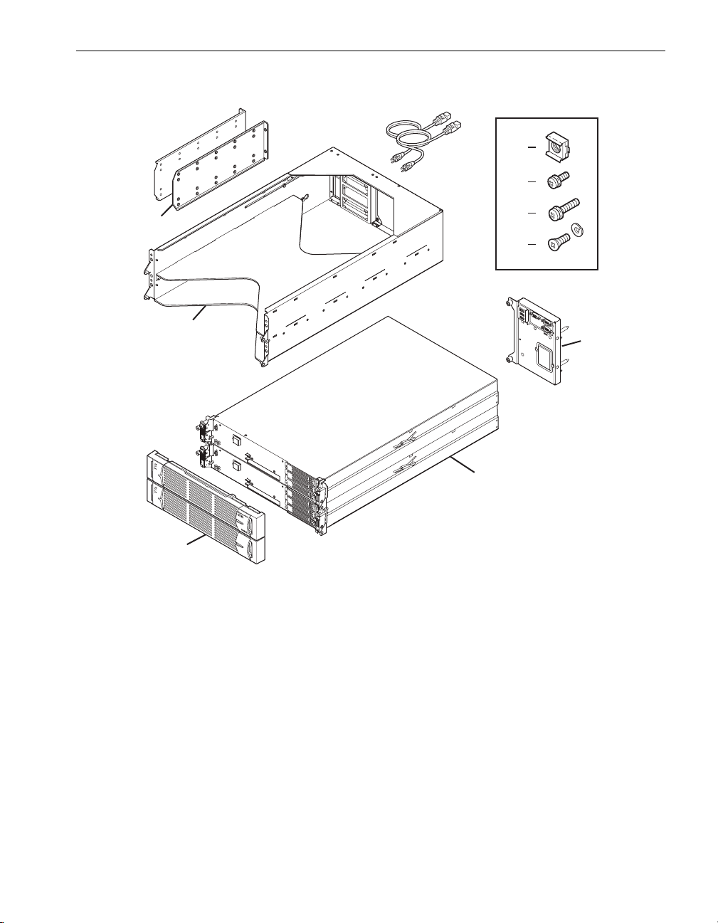
Figure 1-1. Rack-Mounted System Components
Checking the System Components
3
4
5
2
6
7
1
9
10
asys012
1 Shelf unit (1)
2 Rear mounting brackets (2), with one guide screw in each bracket
3 Power cords
4 10-32 cage nuts (8)
5 10-32 x 5/8 in. pan-head crest-cup Phillips-head screws (4)
6 10-32 x 1/2 in. pan-head crest-cup Phillips-head screws (8). Two screws are
installed, one in each rear mounting bracket.
7 10-32 x 1/2 in. counter-sunk screws with lock washers (4)
8 Backplane assembly (1)
9CPU-I⁄ O enclosures (2)
10 Front bezel (1)
8
Unpacking Your System 1-3
Page 14
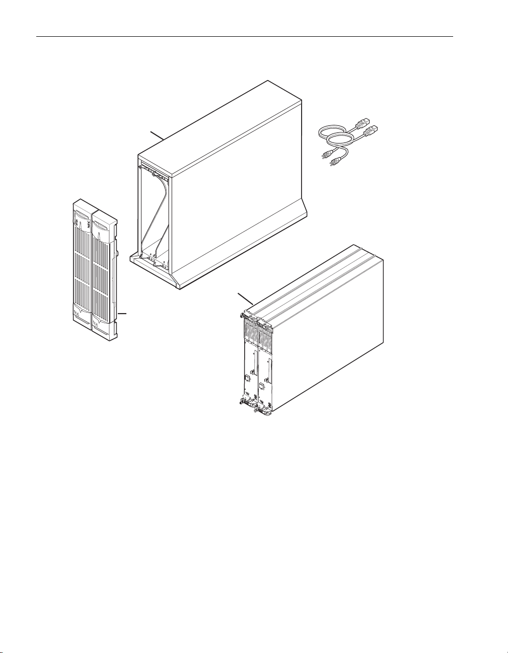
Inspecting the System
Figure 1-2. Pedestal System Components
2
1
3
4
asys013
1 Pedestal case
2 Power cords
3CPU-I⁄ O enclosures (2)
4Front bezel (1)
Inspecting the System
Inspect all equipment for damage. Verify that the equipment has no dents, scratches,
or scrapes. If you notice damage, contact NEC Technical Support.
1-4 Express5800/320Ma: System Installation Guide
Page 15

Verifying the System Serial Number
Ensure that the serial numbers on the system and on the packing list match.
1. Find the label that contains the serial number and site ID affixed to the bottom rear
of the shelf unit.
2. Compare the serial number on the label with the serial number on the packing list.
If the serial numbers do not match, contact NEC Technical Support before installing the
system.
Safety Notices
WARNING
!
RISK OF EXPLOSION IF BATTERY IS REPLACED BY
AN INCORRECT TYPE. DISPOSE OF USED
BATTERIES ACCORDING TO THE INSTRUCTIONS
PROVIDED WITH THE BATTERY.
WARNING
!
If you receive locking power cords with your system,
do not substitute other power cords. Use of the
locking power cords ensures proper grounding of the
system.
Verifying the System Serial Number
WARNING
!
The system uses two power cords to provide
redundant sources of power. To fully remove power
from a system, disconnect both power cords. To
reduce the risk that electrical shock could injure a
person or damage the system, exercise caution when
working in the unit even when only one power cord is
connected.
WARNING
!
To prevent a cabinet from tipping over and injuring a
person or damaging the system, start installing
systems from the bottom of the cabinet upward.
Unpacking Your System 1-5
Page 16

Safety Considerations
WARNING
!
If you replace the modem cable supplied by NEC
Solutions (America), Inc., use a cable with a gauge of
at least 26 AWG to prevent fire.
Safety Considerations
Before installing the system, take the following important precautions:
• Observe all applicable industry safety standards. See the “Safety Notices” on
page 1-5.
• Provide the necessary space and light to safely perform the installation.
• Do not wear conducting objects, such as rings, bracelets, and keys.
Next Steps
Go to Chapter 2, “Installing a Rack-Mountable System” to install a rack-mountable
system in your own cabinet.
Go to Chapter 3, “Installing a Pedestal System” to install a pedestal system,
Go to Chapter 4, “Setting Up Your System” to set up a system that is already mounted
in a cabinet.
1-6 Express5800/320Ma: System Installation Guide
Page 17

Chapter 2
Installing a Rack-Mountable System
Before you install the system, make sure that the site has been prepared as described
in the Express5800/320Ma: Site Planning Guide.
To install your rack-mountable system, see:
• Figure 1-2, which identifies the components of a rack-mountable system
• “Safety Notices” on page 1-5 and “Safety Considerations” on page 1-6
• “Managing Cables” on page 2-1
• “Installing a Rack-Mounted System” on page 2-2
• “Installing the System Components” on page 2-11
Tools required:
• A #2 Phillips-head screwdriver
• A flat-head screwdriver or a cage-nut insertion and extraction tool
2-
Managing Cables
When routing cables within the cabinet, keep all power cords separate from peripheral
and communication cables as much as possible. For example, route all power cords on
one side of the cabinet and all peripheral and communications cables on the other side
of the cabinet, using the cable management rings on your cabinet to constrain the
cords and cables.
Installing a Rack-Mountable System 2-1
Page 18

Installing a Rack-Mounted System
Installing a Rack-Mounted System
Before installing the system, ensure that:
• Your cabinet (if you are installing the system in your own cabinet) meets the
requirements described in the Express5800/320Ma: Site Planning Guide.
• The site has been prepared as described in the Express5800/320Ma: Site
Planning Guide.
If you are using power distribution units (PDUs), install them in your cabinet as
described in Chapter 5, “Installing PDUs” before you install the system.
A rack-mounted system consists of the components shown in Figure 1-2.
To install a rack-mounted system, see the following sections:
• “Numbering the Vertical Rails” on page 2-2
• “Attaching Mounting Brackets to the Cabinet Vertical Rails” on page 2-5
• “Installing the Shelf Unit” on page 2-7
Numbering the Vertical Rails
Each system requires 4U, equal to 12 holes, of vertical space.
NOTE
The cabinet rails and the system are measured in EIA
rack units (U). One U equals 1.75 in. (4.45 cm).
Every three square holes on the EIA square-hole pattern
on the vertical rail equals one U. The square holes on EIA
rails are located in a repeating pattern of 1/2 in. (1.27 cm),
5/8 in. (1.59 cm), 5/8 in. (1.59 cm), as shown in
Figure 2-1.
The middle hole of each U has equal spacing between it
and the holes adjacent to it. In some cabinets, numbers on
the vertical rails identify the middle hole of each U.
2-2 Express5800/320Ma: System Installation Guide
Page 19
Figure 2-1. EIA Square-Hole Pattern on the Vertical Rail
1U
Installing a Rack-Mounted System
1U
5/8 in. (1.59 cm)
5/8 in. (1.59 cm)
1/2 in. (1.27 cm)
If your rack is not already numbered, use a marker or pencil to number the middle hole
of at least the following:
• The 4U in which to install each system
• The 1U in which to install a keyboard, video, and mouse (KVM) switch, if ordered
The following instructions direct you to start numbering the middle hole of the third U in
the cabinet, which is the eighth hole, to leave room at the bottom of the cabinet for the
PDUs.
To number the vertical rails in a cabinet
1. On each of the front rails, number the middle hole of the 4U where you will install
the system. In Figure 2-2, the middle hole of the third, fourth, fifth, and sixth Us are
numbered.
Installing a Rack-Mountable System 2-3
Page 20

Installing a Rack-Mounted System
Figure 2-2. Numbering the Middle Hole of 4U
6
5
4
3
2. If you are installing additional systems in the same cabinet, continue numbering the
middle hole of another 4U for each system.
3. Repeat the preceding steps at the rear vertical rails.
To ensure that the components will be level when you install them, mark the same
holes on the rear rails that you marked on the front vertical rails.
2-4 Express5800/320Ma: System Installation Guide
Page 21

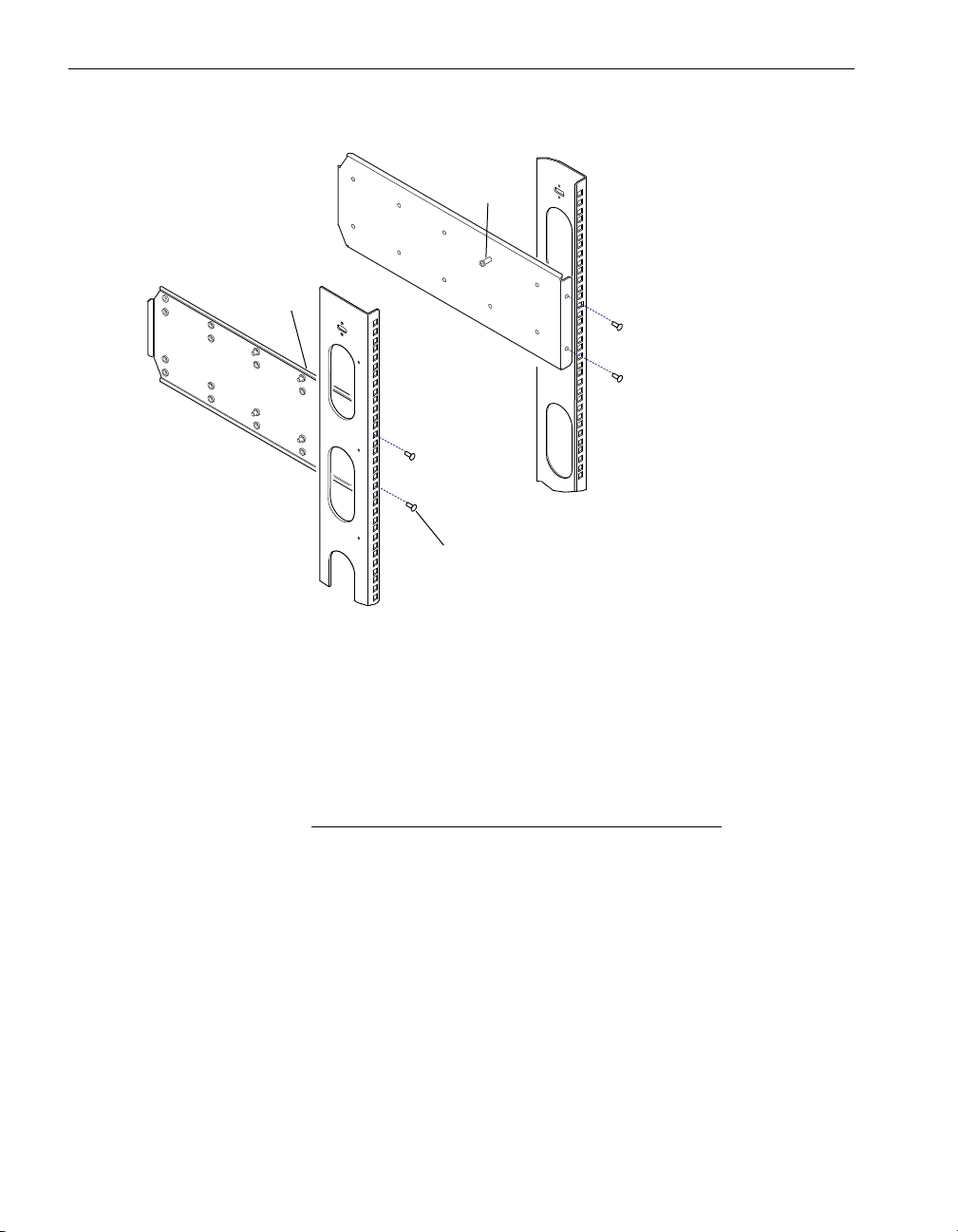
Installing a Rack-Mounted System
Attaching Mounting Brackets to the Cabinet Vertical Rails
Two mounting brackets, one on each rear vertical rail, support the shelf unit.
To attach the mounting brackets
1. On the rear vertical rails, use a pen to mark the holes indicated by dots in
Figure 2-3.
Figure 2-3. Screw Locations on the Rear Vertical Rails
6
5
4
3
2. Position a mounting bracket inside a rear vertical rail, lining up the holes in the
mounting bracket with the two holes you marked on the rear vertical rail. See
Figure 2-4.
3. Insert and tighten two 10-32 x 5/8-in. pan-head crest-cup screws (item 1 in
Figure 2-4) through the marked holes in the rear vertical rails and into the holes in
the mounting bracket.
4. Repeat steps 2 and 3 for the second mounting bracket.
Installing a Rack-Mountable System 2-5
Page 22
Installing a Rack-Mounted System
Figure 2-4. Attaching the Mounting Brackets
3
2
1
asys014
1 10-32 x 5/8-in. pan-head crest-cup screw
2 Right guide screw, 10-32 x 1/2-in. pan-head crest-cup
3 Left guide screw, 10-32 x 1/2-in. pan-head crest-cup
5. Measure the distance between the front and rear vertical rails in the cabinet.
NOTE
Left and right in the following instructions are as seen from
the rear of the cabinet.
• If the rail depth is less than 27 in. (68.58 cm), move the guide screw (item 2 in
Figure 2-4) in the right mounting bracket one hole closer to the rear of the
cabinet.
• If the rail depth is greater than 27 in. (68.58 cm), move the guide screw (item 3)
in the left mounting bracket one hole closer to the front of the cabinet.
2-6 Express5800/320Ma: System Installation Guide
Page 23

Installing the Shelf Unit
WARNING
!
To avoid personal injury or damage to the shelf unit,
two persons are required to insert the shelf unit into
the cabinet and onto the mounting brackets.
1. At the front of the cabinet, insert four cage nuts into each vertical rail, in the
locations shown in Figure 2-5.
Figure 2-5. Cage Nut Locations on Front Vertical Rails
Installing a Rack-Mounted System
6
5
4
3
2
1
ca
ge n
cage
c
age
ca
g
e n
u
t
nut
n
ut
ut
To insert cage nuts, refer to Figure 2-5 and perform the following steps:
a. Position the cage nut so that the flanges are on the top and bottom.
b. Insert the cage nut so that the top flange overlaps the vertical rail.
c. Use a cage-nut insertion tool or your fingers to pull the rest of the cage nut
through so that the bottom flange overlaps the vertical rail.
Installing a Rack-Mountable System 2-7
Page 24

Installing a Rack-Mounted System
2. With two people, one positioned at the front of the cabinet and one positioned at
the rear of the cabinet, insert the shelf unit into the cabinet and onto the mounting
brackets.
a. At the front of the cabinet, slide the shelf unit into the cabinet.
b. At the rear of the cabinet, flex the right mounting bracket towards the side of
the cabinet and guide the shelf unit so that the guide slot at the top right of the
shelf unit (item 1 in Figure 2-6) aligns with the guide screw (item 2) on your
right.
c. At the rear of the cabinet, flex the left mounting bracket towards the side of the
cabinet and guide the shelf unit so that the guide slot at the top left of the shelf
unit (item 1) aligns with the guide screw (item 2) on your left.
Figure 2-6. Mounting the Shelf Unit on the Mounting Brackets
1
2
1
2
2
Rear
1
Front
1 Guide slots
2 Guide screws
2-8 Express5800/320Ma: System Installation Guide
asys018
Page 25

Installing a Rack-Mounted System
3. At the front of the cabinet, slide the shelf unit all the way in.
4. In the locations shown in Figure 2-7, secure the shelf unit to the vertical rails by
inserting and tightening two 10-32 x 1/2-in. counter-sunk screws and lock washers
into each mounting flange on the shelf unit and into the cage nuts behind them.
Figure 2-7. Securing the Shelf Unit to the Front Rails
2
1
asys019
1 10-32 x 1/2-in. counter-sunk screws with lock washers
2 Mounting flange
Installing a Rack-Mountable System 2-9
Page 26

Installing a Rack-Mounted System
5. Secure each side of the shelf unit to a rear mounting bracket with four
10-32 x 1/2-in. screws on each side, including the guide screws, as shown in
Figure 2-8.
Tighten all eight screws.
Figure 2-8. Securing the Shelf Unit to the Mounting Brackets
1
2
asys020
1 Mounting bracket
2 10-32 x 1/2 in. pan-head crest-cup screws with washers
2-10 Express5800/320Ma: System Installation Guide
Page 27

Installing the System Components
1. Install the backplane assembly.
a. At the rear of the system, install the backplane assembly (item 2 in Figure 2-9),
inserting the thumbscrews (item 1) into the screw holes as shown in
Figure 2-9.
b. Slide the backplane assembly slightly to the right and secure it in place by
tightening the thumbscrews.
Figure 2-9. Installing the Backplane Assembly on a Rack-Mounted System
Installing the System Components
1
2
1
asys022c
1Thumbscrews
2 Backplane assembly
Installing a Rack-Mountable System 2-11
Page 28

Installing the System Components
2. If ordered, install the modem assembly.
CAUTION
!
Make sure that the system is powered off. You can install
the modem if the system is turned off and no power cords
are connected to the system. If you must install the
modem assembly while the system is in operation, see the
Express5800/320Ma: Operation and Maintenance Guide.
a. At the rear of the system, remove the metal plate from the backplane.
b. Insert the modem assembly into its slot on the backplane, as shown in
Figure 2-10.
c. Secure the modem assembly in place by tightening the thumbscrews.
Figure 2-10. Installing the Modem Assembly on a Rack-Mounted System
1
2
1
asys054a
1 Thumbscrews
2 Modem assembly
2-12 Express5800/320Ma: System Installation Guide
Page 29

Installing the System Components
3. Install the CPU- I ⁄ O enclosures.
a. Place each CPU- I ⁄ O enclosure on a flat surface and turn the two
thumbscrews (item 1 in Figure 2-11) counterclockwise to loosen them and pull
the two ejector levers down (item 2).
b. Slide each CPU- I ⁄ O enclosure into a shelf and, with the ejector levers in the
open position, slide the CPU-I ⁄ O enclosure all the way into its opening.
WARNING
!
Lifting an enclosure requires two people.
Figure 2-11. Installing the CPU-I/O Enclosures into a Cabinet
1
1
2
2
1 Thumbscrew
2 Ejector lever
Installing a Rack-Mountable System 2-13
asys021a
Page 30

Installing the System Components
c. Push the ejector levers up into the closed position and tighten the thumbscrews
so that the system is installed in the rack as shown in Figure 2-12.
Figure 2-12. System in a Cabinet
4. Attach the bezel.
a. Standing in front of the system, position the bezel so that the LED light
extensions that are inside the bezel are on the left.
b. Press the bezel towards the mounting rails until the bezel snaps into place.
asys024a
2-14 Express5800/320Ma: System Installation Guide
Page 31

Chapter 3
Installing a Pedestal System
Before you install the system, make sure that the site has been prepared as described
in the Express5800/320Ma: Site Planning Guide
To install your pedestal system, see Figure 1-2, which identifies the components of a
pedestal system, “Safety Notices” on page 1-5, and “Safety Considerations” on
page 1-6.
Tools required: None
To install the system in a pedestal case
1. Install the modem assembly.
CAUTION
!
Make sure that the modem is powered off. You can install
the modem assembly if the system is turned off and no
power cords are connected to the system. If you must
install the modem assembly while the system is in
operation, see the Express5800/320Ma: Operation and
Maintenance Guide.
3-
a. At the rear of the system, remove the metal plate from the backplane.
b. Insert the modem assembly into its slot on the backplane, as shown in
Figure 3-1.
c. Secure the modem assembly in place by tightening the thumbscrew.
Installing a Pedestal System 3-1
Page 32

Installing a Pedestal System
Figure 3-1. Installing the Modem Assembly on a Pedestal System
asys056
2. Install the CPU- I ⁄ Oenclosures.
a. Place each CPU- I ⁄ O enclosure on a flat surface and turn the two
thumbscrews (item 1 in Figure 3-2) counterclockwise to loosen them. Pull the
two ejector levers down (item 2).
WARNING
!
Lifting the enclosure requires two people.
b. Slide each CPU- I ⁄ O enclosure into a shelf and, with the ejector levers in the
open position, slide the CPU-I ⁄ O enclosure all the way into its opening.
3-2 Express5800/320Ma: System Installation Guide
Page 33

Installing a Pedestal System
Figure 3-2. Installing the CPU-I/O Enclosures into a Pedestal Case
A
1
1
2
2
asys021a
1 Thumbscrew
2 Ejector lever
Installing a Pedestal System 3-3
Page 34

Installing a Pedestal System
c. Push the ejector levers into the closed position and tighten the thumbscrews
so that the system is installed in the case as shown in Figure 3-3.
Figure 3-3. CPU-I/O Enclosures Fully Inserted in a Pedestal Case
asys26
3. Attach the bezel.
a. Standing in front of the system, position the bezel so that the LED light
extensions that are inside the bezel are on the bottom.
b. Press the bezel towards the mounting rails until the bezel snaps into place.
3-4 Express5800/320Ma: System Installation Guide
Page 35

Chapter 4
To set up your system, see:
• “Ports on the System” on page 4-1
• “Connecting a Monitor, Mouse, and Keyboard” on page 4-3
• “Connecting the System to Ethernet Networks” on page 4-4
• “Connecting the Modem” on page 4-5
• “Connecting an External USB Floppy Disk Drive” on page 4-6
• “Connecting the System to Electrical Power” on page 4-6
Ports on the System
The ports are located at the rear of the system, as shown in Figures 4-1and 4-2. Refer
to these illustrations as you connect cables and power cords to the system.
Your system may contain PCI adapters that require cables. Your system contains a
half-height PCI adapter slot in each CPU-I ⁄ O enclosure. In addition, the system may
contain two full-height PCI adapter slots (expansion slots).
Setting Up Your System
4-
Figure 4-1 shows the rear of a pedestal system that contains PCI adapters in the
half-height PCI adapter slots.
Figure 4-2 shows a rack-mounted system that contains PCI adapters in the standard
half-height slots and in each expansion PCI adapter slot.
When you receive your system from the manufacturer, PCI adapters that were ordered
at the same time the system was ordered are installed. If you need to install PCI
adapters in the system, see the Express5800/320Ma: PCI Adapter Guide and the
Express5800/320Ma: Operation and Maintenance Guide.
Setting Up Your System 4-1
Page 36

Ports on the System
Figure 4-1. Ports on a Pedestal System
1
2
3
4
5
6
7
asys007
1 Ports on PCI adapters in slot 1
2 System 10/100/1000-Mbps Ethernet ports (4)
3 USB ports (3)
4 VGA (monitor) port
5 Serial (COM) ports (2)
6 Power receptacles (2)
7 VTM 10/100-Mbps Ethernet ports (2)
4-2 Express5800/320Ma: System Installation Guide
Page 37

Figure 4-2. Ports on a Rack-Mountable System
Connecting a Monitor, Mouse, and Keyboard
2
1
1 Ports on PCI adapters in PCI expansion slot 3
2 Ports on PCI adapters in PCI expansion slot 2
3 Ports on PCI adapters in PCI slot 1
4 System 10/100/1000-Mbps Ethernet ports (4)
5 USB ports (3)
6 VGA (monitor) port
7 Serial (COM) ports (2)
8 Power receptacles (2)
9 VTM 10/100-Mbps Ethernet ports (2)
10 RJ-11 port on modem
3
54
67
9
8
asys011
Connecting a Monitor, Mouse, and Keyboard
To connect a generic monitor and the V115 mouse and keyboard to the system, see
“Connecting a Generic Monitor” on page 4-3.
Connecting a Generic Monitor
1. Connect the USB cable from the mouse to the USB port located at the back of the
keyboard.
NOTE
Remove the green USB-to-PS2 converter on the USB
cable from the mouse supplied by NEC Solutions
(America), Inc.
Setting Up Your System 4-3
Page 38

Connecting the System to Ethernet Networks
2. Connect the USB cable from the keyboard to one of the system’s USB ports. The
system’s USB ports are interchangeable. Item 3 in Figure 4-1 and item 5 in
Figure 4-2 shows the USB ports on the system.
3. Connect the 15 pin D-sub connector on the VGA cable from the monitor to the
system’s VGA port. Item 4 in Figure 4-1 and item 6 in Figure 4-2 shows the VGA
ports on the system.
4. Connect the VGA cable to the monitor.
Connecting the System to Ethernet Networks
1. Connect the ports for the embedded Ethernet controllers to the network. Provide
an unshielded twisted pair (UTP) cable with RJ-45 connectors for each of the four
system Ethernet ports you plan to use. Connect one end of each cable to a network
port on the system and the other end to an Ethernet wall jack or switch. Item 3 in
Figure 4-1 and item 5 in Figure 4-2 shows the USB ports on the systems.
2. Connect the VTMs, if present, to a maintenance or other network. You need two
UTP cables with RJ-45 connectors. Connect one end of each cable to a VTM
network port. Attach the other end of each cable to an Ethernet wall jack or a
switch. Item 8 in Figure 4-1 and item 9 in Figure 4-2 shows the VTM ports on the
system.
4-4 Express5800/320Ma: System Installation Guide
Page 39

Connecting the Modem
3. If the system contains Ethernet adapters in PCI slots, connect them to a network.
• For ports on copper gigabit Ethernet adapters, use UTP cables with RJ-45
connectors.
• For ports on fiber gigabit Ethernet adapters, use multimode 62.5- or 50-micron,
DUAL fiber cable with LC-type connectors to the PCI adapter, and connectors
on the other end that are compatible with the network switch.
NOTES
1. If you are installing the adapters, install them in pairs,
one in the same slot in each CPU- I ⁄ O enclosure.
2. Add cables in pairs, a cable connected to the same
port in the same slot in each CPU- I ⁄ O enclosure. If
you are using a single pair of ports, attach cables to
the top port(s) of each card and attach both cables to
the same network.
3. The top connector of a port on a U574 Dual-Port Fiber
Gigabit Ethernet Adapter is the transmit port.
For example, in Figure 4-2, U575 Dual-Port Copper Gigabit Ethernet Adapters are
shown in slots 2 and 3 in both CPU-I ⁄ O enclosures.
See the Express5800/320Ma: PCI Adapter Guide for further information.
After you connect the cables and when the system is running, use PROSet to configure
Ethernet ports into teams. For more information about teaming Ethernet ports, see the
Express5800/320Ma: PCI Adapter Guide.
Connecting the Modem
1. Connect the modem cable to the RJ-11 line jack on the modem, item 6 in
Figure 4-1 and item 10 in Figure 4-2.
2. If necessary, attach a Telco adapter to the modem cable.
3. Connect the modem cable to a telephone jack.
Setting Up Your System 4-5
Page 40

Connecting an External USB Floppy Disk Drive
Connecting an External USB Floppy Disk Drive
Use the USB extension cable to connect an optional USB floppy disk drive to a USB
port on the system as follows:
1. Connect the USB extension cable to the cable on the floppy disk drive.
2. Connect the USB extension cable to one of the system USB ports. Item 3 in
Figure 4-1 and item 5 in Figure 4-2 show the USB ports on the system.
NOTES
1. Software generally assigns the letter A to the optional
floppy disk drive when it is first connected to a USB
port. If you subsequently connect the drive to a
different USB port or if the system fails over, software
may assign the letter B to the disk drive.
2. Do not connect the floppy disk drive to the USB hub
on the keyboard. The keyboard does not supply the
power required by the floppy disk drive.
Connecting the System to Electrical Power
This section describes how to connect both the rack-mounted and pedestal systems to
electrical power.
• “System Power Overview” on page 4-6
• “Connecting the System Directly to AC Power (Mains)” on page 4-7
• “Connecting the System to a UPS” on page 4-10
• “Connecting the Systems to Power Through PDUs” on page 4-13
System Power Overview
Your system requires at least two separate and independent AC power outlets, an
A-side power source and a B-side power source. Either source must be capable of
continuing to provide power if power to the other source is lost.
The A-side power source provides power to the top CPU0I/O enclosure and a
keyboard-video-mouse (KVM) switch. If you use a UPS, the UPS is the A-side power
source.
The B-side power source provides power to the bottom CPU- I ⁄ Oenclosure.
A pair of PDUs supplies power to multiple systems and components in a cabinet. The
top PDU in the cabinet provides A-side power. The bottom PDU in the cabinet provides
4-6 Express5800/320Ma: System Installation Guide
Page 41

Connecting the System to Electrical Power
B-side power. See Chapter 5, “Installing PDUs” for more information about installing
PDUs and using them with your system.
WARNING
!
Use only the power cords or cables you receive from
NEC Solutions (America), Inc.
DO NOT MODIFY THE POWER CORDS OR CABLES
you receive with your system.
Failure to comply with this warning will void agency
certification.
Failure to comply with this warning can cause a fire
hazard.
When routing cables within a cabinet, keep power cords separate from peripheral and
communications cables as much as possible. For example, route all power cords on
one side of the cabinet and all peripheral and communications cables on the other side
of the cabinet, using the cable management rings on your cabinet to constrain the
cords and cables.
To configure the system to communicate with a UPS in the case of a power outage,
see the Express5800/320Ma: Software Installation and Configuration Guide.
Connecting the System Directly to AC Power (Mains)
1. Locate two black power cords and two labels, A and B.
2. Attach an A label to one power cord. Connect the power cord according to the
system you have:
• Rack-mounted system: Connect the female end to the receptacle on the top
CPU- I ⁄ O enclosure. Connect the other end to a power source.
• Pedestal system: Connect the female end to the receptacle on the right
CPU- I ⁄ O enclosure. Connect the other end to a power source.
CAUTION
!
Make sure the power interlock mechanism is unlocked
when you insert the power cord. On rack-mounted
systems, the unlocked position is vertical and on pedestal
systems the unlocked position is horizontal. In Figure 4-1
and in Figure 4-2, the interlock mechanism, located
beneath the power connector, is shown in the unlocked
Setting Up Your System 4-7
Page 42

Connecting the System to Electrical Power
position. In Figure 4-3 and in Figure 4-4, the interlock
mechanism is shown in the locked position.
3. Attach a B label to the second power cord. Connect the power cord according to
the system you have:
• Rack-mounted system: Connect the female end to the receptacle on the
bottom CPU- I ⁄ O enclosure. Connect the other end to a second, separate,
power source.
• Pedestal system: Connect the female end to the receptacle on the left
CPU- I ⁄ O enclosure. Connect the other end to a second, separate, power
source.
4. From the front of the system, make sure that the CPU- I⁄ O enclosures are fully
inserted in the shelf unit by tightening, if necessary, the thumbscrews. Then, at the
rear of the system, turn the power interlock mechanisms into the locked position.
Figure 4-3 shows where the two power cords (not color coded) connect to a
rack-mounted system.
Figure 4-3. Connecting a Rack-Mounted System Directly to AC Power
2
1
3
1 B-side power cord
2 A-side power cord
3 AC power outlets
4 AC power (mains) distribution circuit breakers (maximum of 20A)
4
4
3
asys001
Figure 4-4 shows where the two black power cords connect to a pedestal system.
4-8 Express5800/320Ma: System Installation Guide
Page 43

Connecting the System to Electrical Power
Figure 4-4. Connecting a Pedestal System Directly to AC Power
4
3
4
3
1
2
1 A-side power cord
2 B-side power cord
3 AC power outlets
4 AC power (mains) distribution circuit breakers (maximum of 20A)
asys002
Setting Up Your System 4-9
Page 44

Connecting the System to Electrical Power
Connecting the System to a UPS
1. Locate two black power cords and two labels, A and B.
2. Attach an A label to one power cord. Connect the power cord according to the
system you have:
• Rack-mounted system: Connect one end of the cable to the receptacle on the
top CPU- I ⁄ O enclosure. Connect the other, country-specific, end to the UPS.
• Pedestal system: Connect end of the cable to the receptacle on the right
CPU- I ⁄ O enclosure. Connect the other, country-specific, end to the UPS.
CAUTION
!
Make sure the power interlock mechanism is unlocked
when you insert the power cord. On rack-mounted
systems, the unlocked position is vertical and on pedestal
systems the unlocked position is horizontal. In Figure 4-1
and in Figure 4-2, the interlock mechanism, located
beneath the power connector, is shown in the unlocked
position. In Figure 4-3 and in Figure 4-4, the interlock
mechanism is shown in the locked position.
3. Attach a B label to the second power cord. Connect the power cord according to
the system you have:
• Rack-mounted system: Connect one end of the cable to the receptacle on the
top CPU- I ⁄ O enclosure. Connect the other end to a second, separate, power
source.
• Pedestal system: Connect end of the cable to the receptacle on the left
CPU- I ⁄ O enclosure. Connect the other end to a second, separate, power
source.
4. From the front of the system, make sure that the CPU- I⁄ O enclosures are fully
inserted in the shelf unit by tightening, if necessary, the thumbscrews. Then, at the
rear of the system, turn the power interlock mechanisms into the locked position.
To configure the system to communicate with a UPS in the case of a power outage,
see the Express5800/320Ma: Software Installation and Configuration Guide.
4-10 Express5800/320Ma: System Installation Guide
Page 45

Connecting the System to Electrical Power
Figure 4-5 shows how the rack-mounted system connects to power through a UPS.
Figure 4-5. Connecting a Rack-Mounted System to a UPS
1 B-side power cord
2 A-side power cord
3UPS
4 UPS power cord
5 AC power outlets
6 AC power (mains) distribution circuit breakers
(maximum of 20A)
6
5
6
5
1
4
2
3
asys004
Figure 4-6 shows how the pedestal system connects to power through a UPS.
Setting Up Your System 4-11
Page 46

Connecting the System to Electrical Power
Figure 4-6. Connecting a Pedestal System to a UPS
6
5
6
1
5
4
2
3
1 B-side power cord
2 A-side power cord
3UPS
4 UPS power cord
5 AC power source
6 AC power (mains) distribution circuit breakers
(maximum of 20A)
asys005
4-12 Express5800/320Ma: System Installation Guide
Page 47

Connecting the System to Electrical Power
Connecting the Systems to Power Through PDUs
1. Locate one black and one gray power cable (jumper).
2. Connect oneend of each gray cable to the receptacle on the top
CPU- I ⁄ O enclosure. Connect the other end of each gray cable to the top PDU.
CAUTION
!
Make sure the power interlock mechanism is unlocked
when you insert the power cord. On rack-mounted
systems, the unlocked position is vertical and on pedestal
systems the unlocked position is horizontal. In Figure 4-1
and in Figure 4-2, the interlock mechanism, located
beneath the power connector, is shown in the unlocked
position. In Figure 4-3 and in Figure 4-4, the interlock
mechanism is shown in the locked position.
3. Connect the end of each black cable to the receptacle on the left
CPU- I ⁄ O enclosure. Connect the other end of each black cable to the bottom
PDU.
4. From the front of the system, make sure that the CPU- I⁄ O enclosures are fully
inserted in the shelf unit by tightening, if necessary, the thumbscrews. Then, at the
rear of the system, turn the power interlock mechanisms into the locked position.
See Chapter 5, “Installing PDUs” for more information about the PDUs.
Setting Up Your System 4-13
Page 48

Connecting the System to Electrical Power
Figure 4-7 shows the color-coded power cables connected to the systems and PDUs.
Figure 4-7. Connecting the Systems to PDUs
3
3
1
2
4
9 9
8 8
7
4
5
6
5
asys003
1 A-side PDU
2 B-side PDU
3 B-side system power cables (black)
4 A-side system power cables (gray)
5 PDU power cords
6UPS
7 UPS power cord
8 AC power outlets
9 AC power (mains) distribution circuit
breaker (maximum of 20A)
See Chapter 6, “Installing Express5800/320Ma System Software” before you turn on
the system.
4-14 Express5800/320Ma: System Installation Guide
Page 49

Chapter 5
To install PDUs, see:
• “PDU Components” on page 5-1
• “Installing a PDU in a Cabinet” on page 5-2
• “Connecting PDUs to AC Power” on page 5-3
• “Removing a PDU from a Cabinet” on page 5-5
Tool required: #2 Phillips-head screwdriver.
PDU Components
The power distribution units (PDU) should be ordered in pairs. When each PDU is
shipped, mounting brackets are attached to the PUU to form one unit.
Verify that you have the components shown in Figure 5-1, and inspect them to ensure
that they are not damaged. If you notice damage, contact NEC Technical Support.
Installing PDUs
5-
Installing PDUs 5-1
Page 50

Installing a PDU in a Cabinet
Figure 5-1. PDU Components
6
5
1
4
1 PDU
2 Mounting brackets
3 Power cables (one black and one gray) which accompany the system
4Power cord
5 10-32 cage nuts (4)
6 10-32 pan-head screws with captive external tooth washers (4)
Installing a PDU in a Cabinet
You can install one or two pairs of PDUs in a cabinet, for a total of four PDUs. Install
the first pair of PDUs in the bottom two contiguous one-U locations of the cabinet, and
the second pair in two convenient, contiguous one-U locations in the middle of the
cabinet.
For each pair of PDUs, the PDU in the top U provides A-side power. That is, the PDU
in the top location powers one CPU-I ⁄ O enclosure, and is the only source of power to
KVM switches. The PDU in the bottom location provides B-side power. That is, the PDU
in the bottom U provides power to the other CPU-I ⁄ O enclosure and to the other side
of an external storage enclosure.
2
3
ssys110
Removable fasteners attach two reversible mounting brackets to the body of the PDU.
Eight mounting holes on the PDU let you adjust the bracket.
5-2 Express5800/320Ma: System Installation Guide
Page 51

Connecting PDUs to AC Power
To install a PDU
1. For each PDU, insert four cage nuts in the rear vertical cabinet rails. Insert two
cage nuts in each rear rail, in the top and bottom holes of U positions 1 and 2. The
locations in which to install the cage nuts for two PDUs are indicated in Figure 5-2.
For detailed information about installing cage nuts, see “Installing the Shelf Unit”
on page 2-7.
Figure 5-2. Cage Nut Locations: PDU
cage nut
2
ca
g
e
1
ca
ca
n
u
t
g
e
n
u
t
g
e
n
u
t
2. Hold the PDU at the back of the cabinet, so that the power outlets and controls face
you, and the blank side of the PDU faces the inside of the cabinet.
3. Align the screw holes on the mounting brackets with the top and bottom holes of
the U with cage nuts, as follows:
a. Align the first PDU with the U numbered 1 (the bottom U).
b. Align the second PDU with the U numbered 2 (the second U from the bottom).
4. Attach the PDU with four 10-32 screws with one hand while supporting the PDU
with the other.
5. Tighten the screws.
Connecting PDUs to AC Power
At the back of the cabinet, attach a connector end of the country-specific external
power cable to the single PDU inlet connector on the right. Connect the country-specific
connector end to a power source.
CAUTION
!
Connect each PDU to a separate power source.
To connect the PDU to the system, see “Connecting the Systems to Power Through
PDUs” on page 4-13.
Installing PDUs 5-3
Page 52

Connecting PDUs to AC Power
Figure 5-3 shows how to connect PDUs to power sources when one source is a UPS.
Figure 5-3. Connecting a PDU to a UPS
3
1
2
4
1 A-side PDU
2 B-side PDU
3 Power cord for top PDU
4 Power cord for bottom PDU
5UPS
6 UPS power cord
7 AC power sources
8 AC power (mains) distribution circuit breakers
(maximum of 20A)
8
7
8
7
5
6
s4u092b
5-4 Express5800/320Ma: System Installation Guide
Page 53

Removing a PDU from a Cabinet
CAUTION
!
If you are removing both PDUs that provide power to the
same components, turn off the system components.
1. Remove the system from service. Use one of the following procedures:
• Click Start and select Shut Down.
• Press the power button once, if you have enabled Allow system to be
shutdown without having to logon enabled. See the Express5800/320Ma:
System Administrator’s Guide.
2. Remove the power cables from the PDU.
3. Remove the four screws with one hand while supporting the PDU with the other
hand.
4. Slide the PDU out of the cabinet and place the PDU in a safe place.
Removing a PDU from a Cabinet
Installing PDUs 5-5
Page 54

Removing a PDU from a Cabinet
5-6 Express5800/320Ma: System Installation Guide
Page 55

Chapter 6
Installing Express5800/320Ma
System Software
If the operating system has been installed by the manufacturer, a Microsoft Certificate
of Authenticity is placed on the system equipment label at the rear of the system. In this
case, supply the information in Ta b l e 6 - 1 and perform only the procedure described in
“The Post-IPL Procedure” on page 6-9.
If the operating system has not been installed by the manufacturer, review the
information in “Overview of the IPL and Post-IPL Procedures” on page 6-2 and “IPL
Considerations” on page 6-2, supply the information in Ta b le 6- 1 , and perform the
procedure described in “Performing the IPL Procedure” on page 6-6, followed by the
post-IPL procedure.
NOTES
1. The IPL procedure allows you to perform a single IPL
and then duplicate the system disk for bulk
deployment. If you are using a duplicate system disk,
perform only the post-IPL procedure described in
“The Post-IPL Procedure” on page 6-9.
6-
2. Software installation services are available. Contact
NEC Technical Support for details.
Installing Express5800/320Ma System Software 6-1
Page 56

Overview of the IPL and Post-IPL Procedures
Overview of the IPL and Post-IPL Procedures
The IPL procedure installs the following:
• Microsoft Windows Server 2003
On Express5800/320Ma systems, Windows Server 2003 Enterprise Edition and
Service Pack 1 is installed and supported.
• Express5800/320Ma, including ftServer drivers, ftServer Manager, and
Express5800/320Ma Software Availability Manager (SAM)
• Java™ Runtime Environment (JRE) for using the Virtual Technician Module (VTM)
console
• Operating system files that are customized for the systems
• System documentation
IPL Considerations
• Neither the IPL procedure nor the post-IPL procedure mirrors the system disk. To
achieve fault tolerance, mirror it after the installation. See the Express5800/320Ma:
Software Installation and Configuration Guide for instructions.
• Do not attempt to use your Windows Server CD alone to install or reinstall Windows
Server. Instead, use the NEC ExpressBuilder CD (1 of 2) to perform the IPL
procedure. The NEC ExpressBuilder CD (1 of 2) contains customized drivers that
are necessary to run an Express5800/320Ma system properly.
• The Post Installation Check, which runs after the IPL, automatically creates a file
named Versiondate.plt (date represents the file creation time and date) that
contains information about the files that were installed. NEC Technical Support can
use this file to analyze installation problems. This information file is created in the
following folder:
%ProgramFiles%\Stratus\CustomerService\VersionReports
• The Post Installation Check tool, which also runs after the IPL, creates a file named
Postcheck_yyyy_mm_dd_hh_mm.txt in the
%ProgramFiles%\Stratus\Customerservice\Installcheck folder on the system
drive. In the file name, yyyy_mm_dd_hh_mm indicates the year, month, date, hour,
and minute when the file was created.
6-2 Express5800/320Ma: System Installation Guide
Page 57

The Post Installation Check tool verifies that:
– Express5800/320Ma applications are properly installed.
– Correct versions of drivers are properly installed.
– The correct, compiled Managed Object Format (MOF) files are present.
– Express5800/320Ma services are installed and started, except for services
that run only at system startup.
– Third-party applications are properly installed.
– Microsoft hotfixes are installed.
• The IPL procedure takes approximately two and one-half hours to complete.
Mini-Setup Worksheet
Before you start the IPL or Mini-Setup procedure, record site-specific information on
the worksheet shown in Tab le 6- 1 , which lists the information requested by the IPL and
Mini-Setup prompts.
For more information about the settings listed in Ta b le 6 -1 , see the Windows
documentation.
Mini-Setup Worksheet
Table 6-1. Mini-Setup Worksheet
Setting Description Entry
Regional
settings
User name
and
organization
Installing Express5800/320Ma System Software 6-3
The first Customize button changes general
settings (such as location or language); the
appearance of dates, time, numbers, and
currency; and the input locale (the keyboard’s
input language).
The second Customize button changes only the
input locale.
A user name is the name of the person who is
performing the installation.
An organization (an optional field) is the
organization to which a copy of Windows is
licensed.
N/A
User name:
Organization:
Page 58

Mini-Setup Worksheet
Table 6-1. Mini-Setup Worksheet (Continued)
Setting Description Entry
Microsoft
product key
Licensing
mode
System name
and
administrator
password
If Windows Server 2003 was installed by the
manufacturer, you do not need a product key.
The product key is located on the Windows
Server 2003 CD case or on the cover of Windows
Server 2003 documentation.
Windows Server 2003 supports two licensing
modes: per seat and per server.
If you choose Per server, each concurrent
connection to the server requires a separate
Client Access License. If you select this mode,
you can change the mode to the Per Device or
Per User mode later.
If you choose Per Device or Per User, each
computer that accesses the server requires a
separate Client Access License. If you select this
mode, you cannot change the mode to the
per-server mode later.
A system name is a unique computer name that
differs from other computer, workgroup, or
domain names on your network. Mini-Setup
suggests a system name, but you can change
the name. Ask your network administrator for
name recommendations.
Product key:
Check one:
Per server: ________
(Default value)
Per Device or Per User ____
System name:
An administrator password is the password for
the Administrator account that Windows
automatically creates during installation. It is the
logon password for the user whose logon name
is Administrator. Record this password.
Date and time
settings
6-4 Express5800/320Ma: System Installation Guide
Use this dialog box to set the date, time, and time
zone.
Administrator password:
N/A
Page 59

Table 6-1. Mini-Setup Worksheet (Continued)
Setting Description Entry
Performing the IPL Procedure
Networking
settings
Workgroup or
computer
domain
If you have a simple peer-to-peer network, you
may want to click Typical settings.
To configure advanced network options or add
more services during Mini-Setup, click Custom
settings. If you click Custom settings, another
dialog box prompts you for more information.
Note: To join a domain, first set your networking
settings appropriately. Ask your network
administrator for the correct networking settings.
You must join either a workgroup or a domain.
A workgroup is one or more computers with the
same workgroup name. To join a workgroup,
provide a new workgroup name, or use the
workgroup name that Windows suggests during
Mini-Setup.
A domain is a group of computers that are part of
a network, are managed by a domain controller,
and share a common directory database. Joining
a domain requires a computer account in the
domain you want to join. To join a domain during
Mini-Setup, provide the name of an existing
domain, your user name, and your password.
Check one:
Typical settings: ________
Custom settings: ________
Workgroup or domain:
Performing the IPL Procedure
The IPL procedure takes approximately two and one-half (2.5) hours. System
configuration procedures take additional time. See the Express5800/320Ma: Software
Installation and Configuration Guide for information about these configuration
procedures.
Checklist: The IPL Procedure
❏ Prepare for the IPL procedure as described in “Preparing for the IPL Procedure” on
page 6-6.
❏ Perform the IPL procedure as described in “Performing the IPL Procedure” on
page 6-6.
Installing Express5800/320Ma System Software 6-5
Page 60

Performing the IPL Procedure
Preparing for the IPL Procedure
1. Make sure you have the following media:
• NEC ExpressBuilder CD (1 of 2)
• NEC ExpressBuilder CD (2 of 2)
• One of the following:
– For an Express5800/320Ma system, Microsoft Windows Server 2003,
Enterprise Edition CD with Service Pack 1
NOTE
If you are supplying your own Windows Server 2003 CD,
make sure it contains only one operating system. If the CD
contains more than one operating system, the IPL
procedure does not execute correctly.
2. Connect a monitor and keyboard to the system, either directly or through a
keyboard, video, mouse switch.
3. Make sure that the hard disk on which you want to install Express5800/320Ma is
inserted in one of the following locations:
– In a rack-mountable system, in the bottom-most slot in the top enclosure
– In a pedestal system, in the right-most slot in the enclosure on the left
4. Unlatch all other disks. After the IPL, you insert and mirror the disks.
Performing the IPL Procedure
1. If the system is powered on, remove power before starting the IPL. To remove
power from the system, shut down Windows.
2. If any storage enclosures are connected to the system, disconnect them.
3. Turn on power to the system.
a. Verify that the system power cords are plugged into live AC power outlets.
If the system is connected to power distribution units (PDUs), make sure that
the PDUs are plugged into live AC power outlets and are turned on.
b. Turn on power to the monitor.
c. Turn on system power: Press the power button on the enclosure whose power
button LED is green-lit.
4. Insert the NEC ExpressBuilder CD (1 of 2) in the CD-ROM drive of the enclosure
whose power button LED is green-lit.
6-6 Express5800/320Ma: System Installation Guide
Page 61

Performing the IPL Procedure
5. Disable boot monitoring and, optionally, Option ROM for PCI slots.
a. When the system is booting and the progress bar has started to fill, press F2
to enter the BIOS Setup program. An Entering Setup message appears,
but several minutes may elapse before the BIOS Setup program runs.
b. Use the RIGHT ARROW key to select the Advanced tab.
c. To disable boot monitoring, use the DOWN ARROW key to select Monitoring
Configuration. Press ENTER. Use the DOWN ARROW key to select OS
Boot Monitoring. Use the PLUS SIGN (+) key to change the value to
Disabled. Press ESC.
d. If the system contains any PCI adapters that contain option ROMs, the system
boots faster if you disable Option ROM for the PCI slots that contain the
adapters. To disable Option ROM, select Monitoring Configuration on the
Advanced tab. Select each slot that contains an adapter and use the PLUS
SIGN (+) key to change the values to Disabled.
e. Press F10. In the Setup Confirmation dialog box, select Yes and press
ENTER to save the new settings and exit from the BIOS Setup program.
The system reboots after you exit from the BIOS Setup program.
NOTE
Disabling boot monitoring prevents several unnecessary
restarts of the system during the IPL process.
6. Make sure theNEC ExpressBuilder CD (1 of 2) is inserted in the CD-ROM drive
whose power button LED is green-lit.
7. During the next few minutes, the following normally appear:
• A message: Initial Program Load
• A Windows XP splash screen
• A black screen, then a blue screen, with no text
• A Fault Tolerant Server splash screen
8. In the Start Express5800 series system software IPL dialog box, accept the
default setting, Run the Initial Program Load for Express5800/320Ma software
Release 4.1.x.x, and click Next.
NOTES
1. The dialog box advises you to disable boot
monitoring. If you already disabled boot monitoring as
described in step 5, you do not need to do so again.
2. The Open a session in the Windows
Preinstallation Environment option opens a WinPE
command shell.
Installing Express5800/320Ma System Software 6-7
Page 62

Performing the IPL Procedure
3. Do not use a customized CD except with the
supervision of the NEC Technical Support.
9. Follow the prompts to specify the size of the partition that you want the IPL to
create.
Specify a value within the range of the minimum and maximum allowed partition
sizes for your disk, as shown in the dialog box.
NOTE
If you plan to use a disk-management tool to configure the
system disk as a dynamic disk, ensure that the partition
size that you create now is the size that you want. To
extend the partition size after the disk becomes dynamic,
you may need to purchase and use a third-party tool.
10. Follow the prompts to complete the preinstallation steps of the IPL.
11. If Windows Setup displays the message The Setup script file does not
contain a valid Product ID, click OK. Then, in the Your Product Key dialog
box, enter the product key you specified in Ta bl e 6 - 1 and click Next.
12. In the Preinstallation Completed dialog box, click Restart.
NOTE
If the system is left unattended for an extended period of
time after this point, an Unlock Computer dialog box may
prompt you to log in. You do not need to provide a
password to log in and continue the installation process.
13. For the next few minutes, Windows Setup copies files and starts installation of
Windows updates (hotfixes), restarting the computer at several points.
14. When the Windows Server Post-Setup Security Updates dialog box appears,
configure the system to download, but not automatically install, hotfixes. Use the
following guidelines to install the hotfixes:
• You can install Microsoft hotfixes that are released in a Security Bulletin as a
group of security-related hotfixes.
• Obtain validation from NEC Solutions (America), Inc. before you install other
types of hotfixes, such as Microsoft patches that fix a particular problem.
See the Express5800/320Ma ActiveService Network Configuration Guide for more
information about installing hotfixes.
15. Follow the instructions in the Windows Setup Completed dialog box.
6-8 Express5800/320Ma: System Installation Guide
Page 63

16. A few minutes may pass before the system restarts and the post-IPL procedure
starts.
The Post-IPL Procedure
Perform the post-IPL procedure if Windows and Express5800/320Ma were preinstalled
on your system, or if you have just performed the IPL procedure.
Checklist: Performing the Post-IPL Procedure
❏ If you have not already done so, complete the Mini-Setup Worksheet. See
“Mini-Setup Worksheet” on page 6-3.
❏ Respond to Mini-Setup prompts. See “Responding to Mini-Setup Prompts” on
page 6-9.
❏ Complete the post-IPL procedure. See “Completing the Post-IPL Procedure” on
page 6-10.
NOTE
Before proceeding, check for the latest information about
your system and Express5800/320Ma in the Release
Notes: Express5800/320Ma on the NEC ExpressBuilder
CD (2 of 2) shipped with your system.
The Post-IPL Procedure
Responding to Mini-Setup Prompts
1. If you have just performed the IPL procedure, go to step 2. Otherwise:
a. Insert the disk that contains the boot partition in the following location:
– In a rack-mountable system, in the bottom-most slot in the top enclosure
– In a pedestal system, in the enclosure on the left, in its right-most slot
b. Turn on the system, if you have not already done so. See “Performing the IPL
Procedure” on page 6-6.
2. If the Welcome to the Windows Setup Wizard starts, respond to the Mini-Setup
prompts. If prompted by Mini-Setup, enter the license key again. (You are not
prompted for the license key if Windows was installed by the manufacturer.) Use
the information you provided in Ta bl e 6 - 1 to respond to these prompts.
When Mini-Setup is finished, the system reboots.
NOTE
If your system contains VTMs, the mouse and keyboard
may appear unresponsive at some point after the system
Installing Express5800/320Ma System Software 6-9
Page 64

The Post-IPL Procedure
has restarted. This is normal behavior while the virtual
mouse and keyboard are found by the operating system
as new hardware. Responsiveness returns after a short
period of time.
Completing the Post-IPL Procedure
1. When the Welcome to Windows dialog box appears, press CTRL+ALT+DELETE.
2. Log on by using the Administrator account and password you entered during
Mini-Setup and click OK.
3. Two separate end-user licensing agreements (EULAs) appear:
a. Select the appropriate language for the Express5800/320Ma EULA. If you
display the EULA, review it, and then click Close. Click I accept the terms of
the license agreement if you agree to the terms, and then click Continue.
b. Select whether you want to display the Microsoft Quick-Fix Engineering EULA
Addendum. If you display the EULA, review it, and then click Close. Click I
accept the terms of the license agreement if you agree to the terms, and
then click Continue.
4. The installation programs for third-party software run. Be sure to install the
following software, as NEC Solutions (America), Inc. does not support systems that
lack this software.
• When the Java Runtime Environment Wizard starts, follow the prompts to
install JRE, accept the license agreement and the default settings in the
remaining dialog boxes. (The JRE Setup dialog box may become partially
obscured by the progress bars. Click the dialog box to bring it forward.)
CAUTION
!
If the Setup Complete dialog box for any third-party
software appears, click No, I will restart my computer
later, and then click Finish. If you restart the system now,
the installation does not complete properly.
5. When Setup displays the IPL Completed dialog box, click Restart.
6. Restore the default BIOS settings to enable boot monitoring and, optionally, to
enable Option ROM on the PCI slots. While the system is booting, press F2 to enter
the BIOS Setup program. In the BIOS Setup program, press F9 to restore the
default settings, then press F10 to exit from the BIOS Setup program. You must
enable boot monitoring to maintain fault tolerance.
6-10 Express5800/320Ma: System Installation Guide
Page 65

The Post-IPL Procedure
CAUTION
!
If you do not enable boot monitoring after you perform the
IPL, fault-tolerance of the system is compromised.
7. Express5800/320MaAfter the system has restarted, log on again. The Post
Installation Check window appears for several minutes.
8. The Post Installation Check Tool dialog box appears and automatically runs. This
tool verifies that the upgrade was successful and that the system is restored to full
operation. Click Exit to dismiss the Post Installation Check Tool dialog box. See
“IPL Considerations” on page 6-2 for a description of the file created by the Post
Installation Check tool.
9. The message box 'Has the NEC ExpressCluster Web service been set up?' may
appear during the NEC ExpressCluster SRE installation, but will automatically
disappear after 5 seconds. DO NOT take action to this prompt, or the system may
appear to hang.
10. If you are attaching any EMC
a. Download and install the latest QLogic
®
storage systems to the system, do the following:
®
Fibre Channel drivers for
Windows 2003.
– See the Express5800/320Ma: PCI Adapter Guide for information about the
U525 or U526 PCI adapters that provide connectivity to EMC CLARiiON
and Symmetrix
®
storage systems, and instructions for downloading,
extracting, and installing the driver.
–See Attaching an EMC CLARiiON AX100 Storage System to an
Express5800/320Ma System for information about the U531 Optical Fibre
Channel PCI Adapter that provides connectivity to AX100 storage
systems, and instructions for downloading, extracting, and installing the
driver.
b. Install the EMC PowerPath
®
software. See the PowerPath documentation from
EMC.
c. Connect the system to the storage enclosure. If the storage enclosure is part
of a storage area network (SAN), add the system to the SAN.
11. Configure your system. In particular, do the following:
Installing Express5800/320Ma System Software 6-11
®
Page 66

The Post-IPL Procedure
• Mirror the disks.
• If your system contains VTMs, make sure the VTMs contain the most
up-to-date firmware.
• Use PROSet to configure Ethernet ports into teams.
For more information about configuring your system, see the
Software Installation and Configuration Guide.
Express5800/320Ma:
6-12 Express5800/320Ma: System Installation Guide
Page 67

Appendix A
Ordering CRUs
To find the part number for a customer-replaceable unit (CRU), see the following:
• “System CRUs” on page A-2
• “Network Adapters” on page A-3
• “Host Bus Adapters” on page A-3
• “Peripheral Components” on page A-3
• “KVM Switch and Cables” on page A-3
• “System Power Cords” on page A-4
• “PDU and PDU Power Cables” on page A-4
CAUTION
!
Do not attempt to remove or replace hardware
components that are not listed in the CRU tables. Instead,
contact the NEC Technical Support to determine the best
course of action.
A-
Ordering CRUs A-1
Page 68

System CRUs
System CRUs
Ta bl e A - 1 lists the part numbers of customer replaceable units (CRUs) for your system.
Table A-1. System CRUs
Description Part Number
CPU- I ⁄ O enclosure
1GB DDR2-400 DIMM M231
2GB DDR2-400 DIMM M232
Processor kit: Intel
Processor kit: Intel Xeon 3.6 GHz AK-000541
SATA backplane assembly AA-E93400
System backplane assembly AA-E91100
IDE backplane assembly AA-E93500
Fan assembly (CPU or PSU) AS-000394
Virtual Technician Module (VTM) AA-U46300
†
®
Xeon® 3.2 GHz AK-000527
AA-G90730
SATA disk drive, 160GB, 7200 RPM D642
SATA disk drive, 73GB, 10000 RPM D643
SATA disk drive, 400 GB, 7200 RPM D644
SATA disk drive, 160 GB, 7200 RPM D645
Disk slot filler panel AS-000390
Cabinet ground cable AW-002000
CD-ROM drive AK553
DVD-RW drive AK554
† Specify memory and processor configuration when requesting a replacement
CPU- I ⁄ O enclosure. Processors and DIMMs are not CRUs. Their part numbers are
supplied solely for use in configuring a replacement enclosure.
A-2 Express5800/320Ma: System Installation Guide
Page 69

Network Adapters
Ta bl e A - 2 lists the part numbers of the network adapters—network interface cards or
NICs—for your system.
Table A-2. Network Adapters and PCI Adapter Cables
Description Part Number
U575 Dual-Port Copper Gigabit Ethernet Adapter U575
Host Bus Adapters
Ta bl e A - 3 lists the part numbers of host bus adapters (HBAs) for your system.
Table A-3. Host Bus Adapter Cables
Description Part Number
U525 Optical Fibre Channel PCI Adapter AA-U52500
U526 Optical Fibre Channel PCI Adapter AA-U52600
Network Adapters
Peripheral Components
Ta bl e A - 4 lists the part numbers of peripheral components that NEC Solutions
(America), Inc. supplies for your system. For monitor power cords, see Ta bl e A - 9.
Table A-4. Peripheral Components
Description Part Number
USB floppy disk drive, external AA-000400
Keyboard AA-V11520
Mouse AA-V11610
KVM Switch and Cables
Ta bl e A - 5 lists the part numbers of the KVM switch and its cables.
Table A-5. KVM Switch CRUs
Description Part Number
Four VGA and USB cables B40500-10
Ordering CRUs A-3
Page 70

System Power Cords
Table A-5. KVM Switch CRUs
Description Part Number
One VGA and USB extension cable, 6 ft (1.82m) B40501-06
System Power Cords
Ta bl e A - 6 lists the part numbers of the power cords that NEC Solutions (America), Inc.
supplies to connect your system directly to AC power. Ta bl e A - 7 lists the part numbers
of the power cables that connect the system to an uninterruptible power supply (UPS).
Table A-6. System Power Cords
Power Cord Part Number
North America (Chicago), NEMA 5-15, 15A, 100-127 VAC,
50-60 Hz, 7 ft
North America domestic, NEMA 5-15, 15A, 100-127 VAC,
50-60 Hz, 15 ft
North America and Japan, locking power cord, NEMA L6-20,
20A, 200-240 VAC, 50 Hz, 4.5m
International, locking power cord, IEC-309, 16A, 200-240 VAC,
50 Hz, 4.5m
Table A-7. Power Cords from a System to a UPS
Power Cord Part Number
North America and Japan, NEMA 5-15 to IEC-C13, 120 VAC,
15 ft (4.5m)
North America and Japan, locking power cord, NEMA L6-20 to
IEC-C13, 200-240 VAC, 50 Hz, 15 ft (4.5m)
International, IEC-320 C14 to IEC-320 C13, 250 VAC 3.5m B50301-35M
PDU and PDU Power Cables
Ta bl e A - 8 lists the part numbers of the PDU, the power cords that connect the PDU to
external power and that connect the PDU to a UPS, and the power cables that connect
the system and storage enclosures to a PDU.
B50101-07
B50104-15
B50161-45M
B50153-45M
B50104-15
B50161-45M
A-4 Express5800/320Ma: System Installation Guide
Page 71

PDU and PDU Power Cables
Table A-8. PDU and PDU Power Cords
Description Part Number
PDU AA-P41104
PDU power cords to external power
NEMA L6-20, 20A, 250 VAC, 50-60 Hz, 15 ft (4.5m) B50155-45M
NEMA L6-30, (Receptacle must be fused at no more than
20A), 30A, 250 VAC, 50-60 Hz, 15 ft (4.5m)
IEC-309, 20A, 250 VAC, 50-60 Hz, 15 ft (4.5m) B50154-45M
PDU power cords to a UPS
North America and Japan, NEMA L6-20 to IEC-320 C19,
208V, 15 ft (4.5m)
International, IEC-320 C14 to IEC-320 C19, 230V 3.5m B38003
PDU power cables (jumper cables from PDU to system)
Gray, IEC-320 C13 to IEC-320 C14, 10A, 250V, 2.0m B50502-02M
Black, IEC-320 C13 to IEC-320 C14, 10A, 250V, 2.0m B50503-02M
B50156-45M
B50155-45M
Ordering CRUs A-5
Page 72

PDU and PDU Power Cables
A-6 Express5800/320Ma: System Installation Guide
Page 73

Index-Index
A
accessories box, contents, 1-1
adapters. See PCI adapters
Administrator account password
setting in Mini-Setup program, 6-4
A-side power source, 4-6
B
backplane assembly
IDE
ordering, A-2
SATA
ordering, A-2
system
installing, 2-11
ordering, A-2
bezel
pedestal system
illustrated, 1-4
installing, 3-4
rack-mount system
illustrated, 1-3
installing, 2-14
BIOS
changing settings, 6-7
boot monitoring
disabling, 6-7
enabling, 6-7
B-side power source, 4-6
C
cabinets
numbering rail units (U), 2-2
cables
Ethernet network, 4-5
from system to UPS, ordering, A-4
managing, 2-1, 4-7
power (PDU), ordering, A-4
routing, 2-1, 4-7
USB, ordering, A-3, A-4
cage nuts
front rail locations, 2-7
illustrated, 1-3, 1-4
CD-ROM drive, ordering, A-2
checklists
IPL procedure, 6-5
post-IPL procedure, 6-9
COM ports
illustrated, 4-2, 4-3
CPU fan assembly
ordering, A-2
CPU-I/O enclosures
installing, 2-13, 3-2
ordering, A-2
D
damage, inspecting for, 1-4
date and time settings of Mini-Setup
program, 6-4
disk drives
external floppy, 4-6
ordering, A-3
location during IPL, 6-6
SATA
ordering, A-2
states during IPL, 6-6
disk partitions
during IPL, 6-8
disk slot filler panel, ordering, A-2
disk space requirements
during IPL, 6-6
documentation, system, 6-2, 6-11
drive letter, floppy disk drive, 4-6
DVD-R/W drive
ordering, A-2
E
EMC PowerPath installation, 6-11
Index-1
Page 74

Index
enclosures
installing, 2-13, 3-2
ordering, A-2
Ethernet networks
connecting to PCI adapters, 4-5
connecting to ports, 4-4
connecting to VTM, 4-4
Ethernet ports
system
illustrated, 4-2, 4-3
VTM
illustrated, 4-2
Express5800/320Ma EULA, 6-10
Express5800/320Ma Series System Software
IPL procedure, 6-5
post-IPL procedure, 6-9
extension cables
USB, ordering, A-4
VGA, ordering, A-4
external floppy disk drive
connecting, 4-6
drive letter, 4-6
ordering, A-3
F
floppy disk drive
connecting, 4-6
drive letter, 4-6
ordering, A-3
front vertical rails, cage nut locations, 2-7
ftServer Management Console. See ftSMC
ftServer Management Tools. See ftSMC
ftSMC, 6-2
shortcut, 6-11
G
ground cables, ordering, A-2
H
Help and Manuals shortcut, 6-11
I
IDE backplane assembly
ordering, A-2
Initial Program Load (IPL) procedure
CDs required, 6-6
checklist, 6-5
disk states during, 6-6
media required, 6-6
Open a session in the Windows
Preinstallation Environment
option, 6-7
post-IPL procedure, 6-9
preparing for, 6-5
Start Express5800/320Ma System
Software IPL dialog box, 6-7
system disk location, 6-6
time to complete, 6-5
inspecting the system, 1-4
installation
Express5800/320Ma system software, 6-1
installation information file, 6-2
installing
Java 2 Runtime Environment, 6-10
J
Java 2 Runtime Environment. See JRE
JRE, 6-10
K
keyboards
connecting to system, 4-3
ordering, A-3
USB hub restrictions, 4-6
L
licensing mode settings of Mini-Setup
program, 6-4
M
Microsoft EULA, 6-10
Mini-Setup program, 6-9
modem assembly
connecting cable, 4-5
installing, 2-12, 3-1
monitor
connecting
table top, 4-3
mounting brackets
PDUs, 5-2
system, 2-5
mouse
Index-2 Express5800/320Ma: System Installation Guide
Page 75

Index
connecting to keyboard, 4-3
ordering, A-3
N
NEC ExpressBuilder CD (2 of 2), 6-6
networking settings of Mini-Setup program, 6-5
P
password, Administrator account, 6-4
PCI adapters
connecting, 4-5
Ethernet networks, 4-5
installed, 4-1
ordering, A-3
slots, 4-1
See also specific adapter part numbers
PDUs
components, 5-1
cables, 5-2
illustrated, 5-2
mounting brackets, 5-2
connecting to power sources, 5-3
connecting to system, 4-13, 4-14
installing, 5-2, 5-3
maximum number in a cabinet, 5-2
ordering, A-4
power cords, 5-2
removing from cabinet, 5-5
ports, 4-1
Ethernet
system, 4-2, 4-3
VTM, 4-2, 4-3
pedestal system, illustrated, 4-2
rack-mountable system, illustrated, 4-3
RJ11, 4-3
serial (COM), 4-2, 4-3
USB, 4-2
VGA, 4-2
Post Installation Check Tool, 6-11
Post Installation Check tool, 6-2, 6-11
Postcheck_yyyy_mm_dd_hh_mm.txt file, 6-2
post-IPL procedure
checklist, 6-9
completing, 6-10
power (AC)
sources, 4-6
power cables
ordering, A-4
power cords
color coded, 4-13
illustrated, 4-14
illustrated, 1-3
monitor, ordering, A-5
PDU, 5-2
connecting to AC, 5-3
connecting with a UPS, illustrated, 5-4
safety precautions, 4-7
system
connecting, 4-7
connecting, illustrated, 4-8
ordering, A-5
tape drive, ordering, A-5
to UPS, A-4
power distribution unit (PDU). See PDUs
power receptacles
illustrated, 4-2, 4-3
power, AC
connecting to pedestal system, 4-9
connecting with PDUs, 4-13, 5-3
connecting with UPS, 4-10
powering up
server systems, 6-6
PowerPath installation, 6-11
product key, Windows
setting of Mini-Setup program, 6-4
Q
QLogic Fibre Channel drivers
installing for U525 and U526 Optical Fibre
Channel PCI Adapters, 6-11
R
rack, 2-2
system requirements, 2-2
rail unit (U)
defined, 2-2
illustrated, 2-3
rails, numbering, 2-3
rear vertical rails, screw locations, 2-5
regional settings of Mini-Setup program, 6-3
reinstalling Windows Server 2003, 6-2
removing power, 1-5
RJ-11 port
illustrated, 4-3
Index-3
Page 76

Index
S
safety
installation, 1-6
notices, 1-5
SATA backplane assembly
ordering, A-2
SATA disk drive
ordering, A-2
screw locations
front rails, 2-7
rear rails, 2-5
serial (COM) ports
illustrated, 4-2, 4-3
serial numbers, system, 1-5
system documentation, 6-2
systems
accessories, listed, 1-1
components
illustrated, 1-3, 1-4
listed, 1-1
power, removing from service, 5-5
setting up, 4-3
systems, installing, 2-2
attaching mounting brackets, 2-5
connecting to Ethernet networks, 4-4
inspecting for damage, 1-4
reporting damage, 1-4
tools, 2-1, 3-1
T
third-party software during a System Software
installation, 6-10
tools, required for installing, 2-1, 3-1
floppy disk drive, connecting, 4-6
hubs, use restrictions, 4-6
ports
illustrated, 4-2, 4-3
user name setting of Mini-Setup program, 6-3
V
Versiondate.plt file, 6-2
VGA cables
extension cable, ordering, A-4
ordering, A-3
VGA port
illustrated, 4-2, 4-3
Virtual Technician Module. See VTM
VTM
Ethernet ports
illustrated, 4-2, 4-3
ordering, A-2
W
Welcome to the Windows Setup Wizard, 6-9
Welcome to Windows Logon dialog box, 6-10
Windows Server 2003
CD, 6-6
reinstalling, 6-2
Windows Setup dialog box, 6-8
workgroup or computer domain settings of
Mini-Setup program, 6-5
U
U (rack unit)
defined, 2-2
illustrated, 2-3
numbering, 2-3
requirements, 2-3
U525 adapter
ordering, A-3
U575 adapter
ordering, A-3
UPS, connecting, 4-10
USB
cables, ordering, A-3, A-4
Index-4 Express5800/320Ma: System Installation Guide
 Loading...