

Page 1

Express5800/320Ma:
Technical Reference Guide
NEC Solutions (America), Inc.
NR550
Page 2

Notice
The information contained in this document is subject to change without notice.
UNLESS EXPRESSLY SET FORTH IN A WRITTEN AGREEMENT SIGNED BY AN AUTHORIZED REPRESENTATIVE
OF NEC, NEC MAKES NO WARRANTY OR REPRESENTATION OF ANY KIND WITH RESPECT TO THE
INFORMATION CONTAINED HEREIN, INCLUDING WARRANTY OF MERCHANTABILITY AND FITNESS FOR A
PURPOSE. NEC assumes no responsibility or obligation of any kind for an y errors contained herein or in connection with
the furnishing, performance, or use of this document.
Software described in NEC (a) is the property of NEC and/or its licensees, (b) is furnished only under license, and (c) may
be copied or used only as expressly permitted under the terms of the license.
NEC documentation describes all supported features of the user interfaces and the application programming interfaces
(API) developed by NEC and/or its licensees. Any undocumented f eatures of these interfaces are intended solely for use
by NEC personnel and are subject to change without warning.
This document is protected by copyright. All rights are reserved. No part of this document may be copied, reproduced, or
translated, either mechanically or electronically, without the prior written consent of NEC Solutions (America), Inc.
The NEC Solutions (America), Inc. logo, Express5800/320Ma, and the Express5800/320Ma logo, are trademarks of NEC
Solutions (America), Inc. ActiveService Network is a trademark of Stratus Technologies Bermuda, Ltd. All other
trademarks and trade names are the property of their respective owners.
Manual Name: Express5800/320Ma: Technical Reference Guide
Part Number: NR550
Express5800/320Ma Software Release Number: 4.1.0
Publication Date: January 2006
NEC Solutions (America), Inc.
10850 Gold Center Drive, Suite 200
Rancho Cordova, CA 95670
© 2006 NEC Solutions (America), Inc. All rights reserved.
Page 3

Contents
Preface vii
1. ftServer Drivers and Services 1-1
ftServer drivers 1-1
Board Instance Driver 1-1
Fibre Channel Drivers 1-1
SCSI Port Duplex Driver 1-2
fIPMI Driver 1-2
ATI Video Driver 1-2
Virtual Technician Module (VTM) Mailbox Driver 1-2
VTM Dump Driver 1-3
srasata.sys Driver 1-3
ftServer services 1-3
2. Express5800/320Ma System Features 2-1
Administering an ftGateway Group Manually 2-1
Managing MTBF Statistics 2-3
Error Detection and Handling 2-3
MTBF Calculation and Effects 2-4
Displaying MTBF Information 2-5
Changing the MTBF Threshold 2-6
ftServer Manager Event Handling 2-7
ASN Connection Retry Cycle 2-7
3. ftSMC Component Properties and Actions 3-1
ftSMC Component Properties 3-1
ftSMC Component Actions 3-24
4. System Alarm Messages 4-1
SNMP Traps 4-3
Contents iii
Page 4

Contents
Device State and Threshold Alarms 4-3
ftGateway Alarm Messages 4-10
Miscellaneous Alarms 4-10
5. BIOS Setup 5-1
Before You Change BIOS Settings 5-1
Starting the ftServer Setup Utility 5-2
Navigating and Using the ftServer Setup BIOS Setup Menus 5-2
Legend Bar 5-2
Menu Bar 5-3
Help 5-4
Restoring Default Values Feature 5-5
ftServer Setup Menus 5-5
Main Menu 5-6
Advanced Menu 5-8
Advanced Processor Configuration Submenu 5-9
I/O Device Configuration Submenu 5-10
PCI Configuration Submenu 5-13
Console Redirection Submenu 5-14
Monitoring Configuration Submenu 5-15
Security Menu 5-17
Boot Menu 5-19
Exit Menu 5-21
Summary Screen 5-22
Index Index-1
iv Express5800/320Ma: Technical Reference Guide
Page 5

Figures
Figure 2-1. ftServer Manager Event Handling 2-7
Figure 5-1. ftServer Setup Menu Bar 5-3
Figure 5-2. Main Menu 5-6
Figure 5-3. Advanced Menu 5-9
Figure 5-4. Advanced Processor Configuration Submenu 5-10
Figure 5-5. I/O Device Configuration Submenu 5-11
Figure 5-6. PCI Configuration Submenu 5-13
Figure 5-7. Console Redirection Menu 5-14
Figure 5-8. Monitoring Configuration Submenu 5-16
Figure 5-9. Security Menu 5-18
Figure 5-10. Boot Menu 5-20
Figure 5-11. Exit Menu 5-21
v Express5800/320Ma: Technical Reference Guide
Page 6

Tables
Table 2-1. ftSMC System Inventory Component Actions 2-1
Table 2-2. Example MTBF Calculation 2-5
Table 2-3. Default Settings for Alarm Re-send Parameters 2-8
Table 3-1. ftSMC System Inventory Component Properties 3-1
Table 3-2. ftSMC System Inventory Component Actions 3-24
Table 4-1. Alarm IDs (30100 - 30413) 4-3
Table 4-2. Alarm IDs (30550 - 31863) 4-4
Table 4-3. Alarm IDs (30750 - 31155) 4-5
Table 4-4. Alarm IDs (31900 - 32263) 4-5
Table 4-5. Alarm IDs (30850 - 31453) 4-6
Table 4-6. Alarm IDs (32350 - 32663) 4-7
Table 4-7. Alarms IDs (32500 - 32713) 4-7
Table 4-8. Alarm Messages and Message Destinations 4-8
Table 4-9. ftGateway Alarm Messages 4-10
Table 4-10. Miscellaneous Alar m Me ssa ge s an d M essage
Destinations 4-10
Table 5-1. Legend Bar Keys and Functions 5-3
Table 5-2. Menu Bar Selections 5-4
Table 5-3. Main Menu Features 5-7
Table 5-4. Advanced Processor Configuration Features 5-10
Table 5-5. I/O Device Configuration Fea tures 5-11
Table 5-6. PCI Configuration Features 5-13
Table 5-7. Console Redirection Features 5-15
Table 5-8. Monitoring Configuration Featur es 5-16
Table 5-9. Security Menu Features 5-19
Table 5-10. Exit Menu Features 5-22
Tables vi
Page 7

Purpose of This Manual
The Express5800/320Ma: Technical Reference Guide provides technical reference
information for Express5800/320Ma 3.2 GHz, 3.6 GHz, and Dual-Core systems.
Audience
This manual is intended for those who adm inister or troubleshoot Expr ess5800/320Ma
3.2 GHz, 3.6 GHz, and Dual-Core systems.
Notation Conventions
This document uses the notation conventions described in this section.
Warnings, Cautions, and Notes
Warnings, cautions, and notes provide special information and have t he following
meanings:
WARNING
!
A warning indicates a situation where failure to take
or avoid a specified action could ca use bodily harm or
loss of life.
Preface
CAUTION
!
A caution indicates a situation where failure to t ake or
avoid a specified action could damage a hardwar e device,
program, system, or data.
NOTE
A note provides important information about the opera tion
of an Express5800/320Ma system.
Typographical Conventions
The following typographical conventions are used in Express5800/ 320Ma docu men ts:
Preface vii
Page 8

Preface
• The bold font emphasizes words in te xt or indicates te xt that you type , the name of
a screen object, or the name of a programming element. For example:
Before handling or replacing system components, make sure that you are
properly grounded by using a grounded wrist strap.
In the System Properties dialog box, click the Hardware tab.
Call the RegisterDeviceNotification function.
• The italic font introduces new terms and indicates programmin g and command-line
arguments that the user defines. For example:
Many hardware components are custom er -r ep la cea b le un its (CRUs), which
can be replaced on-site by system adm inistrators with minimal tr aining or tools.
copy filename1 filename2
Pass a pointer for the NotificationFilter parameter
• The monospace font indicates sample program code and output, including
message text. For example:
#include <iostream.h>
Getting Help
If you have a technical question about Express5800/320Ma hardware or software, try
these online resources first:
• Online support from NEC Technical Support. You can find the latest technical
information about an Express5800/320Ma through online product support at the
NEC Technical Support Web site:
• Online product support for Microsoft
support is the computer manufacturer wh o provided your software, or an
authorized Microsoft Support Provider . You can also find the latest technical
information about Microsoft Windows
product support at the Microsoft Help and Support Web site:
If you are unable to resolve your questions with t he help available at these online sites,
and the Express5800/320Ma system is covere d by a service agreement, please
contact NEC Technical Support (866-269-1239).
The operation completed successfully.
http://support.necsam.com/servers/
®
products. Your primary source for
®
and other Microsoft products through online
http://support.microsoft.com/
viii Express5800/320Ma: Technical Reference Guide
Page 9

Notices
Preface
• All regulatory notices are provided in the site planning guide for your system.
• Although this guide documents modem functionality, modems are not av ailab le f or
all systems. Ask your sales representative about modem availability.
• ActiveService Network (ASN) is not currently available , but may be ordered in the
future.
Preface ix
Page 10

Preface
x Express58 00/320Ma: Technical Reference Guide
Page 11

Chapter 1
This chapter provides technical reference information about ftServer drivers and
ftServer services.
ftServer drivers
This section provides technical reference information for the Board Instance driver,
Fibre Channel (FC) driver, SCSI port duplex driver, Intelligent Platform Management
(IPMI) driver, ftServer ATI Video Driv er, sravtmmb.sys, sravtmdp.sys, and srasata.sys.
Board Instance Driver
The Board Instance driver (srabid) computes the overall state of the element, including
enclosed components, to determine whether the element ca n be safely brough t online
or taken offline. It also gathers information about PCI devices and PCI functions in the
system so that you can use ftServer Management Console (ftSMC) to view information
about and control PCI adapters.
Fibre Channel Drivers
ftServer Drivers and Services
1-
The Fibre Channel PCI Adapter requires the FC driver srau529.sys.
The FC driver:
• Supports dynamic insertion and removal of FC disks
• Interfaces with Windows HAL, PnP Manager, and SCSI Port Duplex driver
• Maintains information about the Fibre Channel PCI Adapter properties, including
the fault-toler ant state . It returns appropriate error codes to the SCSI port driver in
case of hard disk and adapter failures.
• Supports dynamic insertion and removal (hot-plug PCI) of I/O elements that
contain PCI adapters
ftServer Drivers and Services 1-1
Page 12

ftServer drivers
For information about the drivers for EMC Fibre Channel (FC) st orage systems, see the
EMC documentation supplied with your storage system. Also, refer to the EMC Web
site for the latest driver updates approved and qualified by EMC for your
Express5800/320Ma system.
SCSI Port Duplex Driver
The SCSI Port Duplex driver:
• Provides redundant paths to disk devices on a Fibre Channel PCI Adapter ports.
• Handles error recovery.
fIPMI Driver
The IPMI driver (sraipmi) is an Intelligent Platform ftServer Management device driver
for the Baseboard Management Controller (BMC). This driver provides an interface
between the BMC and the system management software.
ATI Video Driver
The ATI Video driver controls the video display on systems with embedded ATI video
adapters and supports fault-tolerance at the software level. It comprises three files:
• sra_atim.sys, the miniport driver
• sra_atid.dll, the display driver
• sra_ati.inf, the plug and play information file
Virtual Technician Module (VTM) Mailbox Driver
The sravtmmb.sys driver, the Virtual Technician Module (VTM) mailbox driver, is the
Express5800/320Ma system’s primary communication interface with the VTM. The
system typically uses the mailbox driver for firmware burns, device polling, and device
configuration. Also, the ASN service uses the mailbox driver to configure parameters
for system calls over the ActiveNetwork Service.
1-2 Express5800/320Ma: Technical Reference Guide
Page 13

VTM Dump Driver
The sravtmdp.sys driver, the VTM dump driver , controls the process of g etting a dump
of VTM adapter memory and registers. The host initiates a dump in the event of a
heartbeat failure or other errors from the VTM. VTM initiates a dump of itself if it detects
a fatal error. You can also request a dump from the VTM Homepage.
srasata.sys Driver
The srasata.sys driver controls the SATA internal disks. It does the following:
• Supports dynamic insertion and removal of SATA disks.
• Interfaces with Windows Hardware Abstraction Layer (HAL), plug-and-play (PnP)
Manager, and the SCSI Port Duplex driver.
• Maintains information about the SATA adapter's properties, including the
fault-tolerant state. It returns appropriate error codes to the SCSI P ort Duplex driver
in the event of hard disk or adapter failures.
ftServer services
Express5800/320Ma systems have a layer of software fault-tolerant services that run
as Windows-based services. These services constantly monitor for, and respond to,
hardware problems. The name of each service is listed, followed by its executable
name (as seen in task manager) and a short description.
ftServer services
• Alarm (Sra_Alarm.exe) sends notice of alarm conditions to various locations that
can include NEC Technical Support or your service representative, and a
customer’s pager or email.
• eService (eService.exe) copies BMC events into the Windows Application event
log. It also provides an interf ace to the BMC fo r environmental sensor related tasks .
• Inventory (Sra_Inventory.exe) manages the inventory of hardware and software
on the system.
• Maintenance and Diagnostics (Sramad.exe) monitors and controls hardware
and software modules that participate in th e added value functions. Th is service is
required for Active Upgrade software to function. It performs the following:
– Automatically restarts devices after a transient fault
– Computes safe-to-pull state of devices working in partnership
– When possible, sets the LEDs of devices to indicate their state
ftServer Drivers and Services 1-3
Page 14

ftServer services
• Policy (Policy.exe) identifies alarm conditions by filtering and correlating
Express5800/320Ma hardware and software events.
• Provider Manager (Srasvc.ex e) provides enhanced reliability of ftSMC monitoring
capabilities by isolating Express5800/320Ma system providers from faults in either
Windows Management Instrumentation (WMI) or third party providers.
• RAS (Sra_Ras.e xe) hand les connections to the Activ eService Network (ASN) hub
for systems that do not have VTMs.
• RPC Provider (Rpcprov.exe) stores and retrieves information to and from the
Sra_Ras service (for systems without VTMs) or to the VTM.
• Software Availability Manager (sraSAMService.exe) monitors system
performance and critical ev e nts and sends alerts based on user-def ined threshold
parameters.
• SSN (Sra_Ssn.ex e). On Express5800/ 320Ma systems, the ActiveService Network
(ASN) service synchronizes VTM adapter settings with the host, enabling a
communication path between VTM driv ers and host, and enabling ASN
communication.
– Collects information about the system and generates state change inf ormation
– Controls system hardware to bring up and bring down devices
– Generates traces for use in troubleshooting problems.
– Initiates PnP enumeration when required
• Storage Manager (Srasvc.exe) monitors the fault-tolerant state of storage
subsystems and provides that information to ftSMC.
• Storage Manager (Srasvc.exe -group local) provides system management for
storage devices.
• Sysmgt Startup (Sra_SysmgtStartup.exe) initiates setup for System
Management services.
1-4 Express5800/320Ma: Technical Reference Guide
Page 15

Chapter 2
Express5800/320Ma System Features
This chapter provides technical reference information for the following
Express5800/320Ma 3.2 GHz, 3.6 GHz, and Dual-Core system features:
• Configuring an ftGateway group manually
• Managing mean time between failures (MTBF) statistics
• ftServer Manager event handling
• A detailed description of the ASN connection retry cycle
Administering an ftGateway Group Manually
Normally, you use the ActiveService Manager to configure a system’s relationship to
an ftGateway group. This ensures that NEC Technical Support database will match the
configuration of your Express5800/320Ma’s ftGateway. See the Express5800/320Ma
ActiveService Network Configuration Guide for information about configuring ASN
connectivity using an ftGateway Group.
However, under certain circumstances, yo u may be a sked by NEC Technical Sup port
or your service representative to administer an ftGateway group manually. Refer to the
information in this section to administer an ftGateway group manually.
2-
Table 2-1 describes the four actions associated with the ftGateway Group node.
Table 2-1. ftSMC System Inventory Component Actions
Action Description
Create ftGateway
Group
Join ftGatewa y
Group
Leave ftGateway
Group
Remove ftGateway
Group
Express5800/320Ma System Features 2-1
Creates a new ftGateway group using a customer-supplied name for the
group.
Adds a slave system to an existing ftGateway group.
Removes a slave system from an ftGateway group.
Removes an ftGatew ay group. You must remove all slave systems from the
group prior to executing this action.
Page 16

Administering an ftGateway Group Manually
To create a new ftGateway group
1. Access the system that is to be the gateway system. Start ftSMC.
2. In ftSMC, double-clic k the ftServer Configuratio n node to e xpand the child nodes
beneath it.
3. Right-click the ActiveService Network icon and click Create ftGateway Group.
4. In the Create ftGateway Group on ActiveService Network dialog box, type the
name you want to give the ftGateway group in the Group Name box.
5. In the Create ftGateway Group on ActiveService Network dialog box, type the
password you want to use to access the ftGateway group in the Group Pass wor d
box. Click Finish.
To add a slave system to an ftGateway group
1. Access the slave system that y ou want to add to the ft Gatewa y g roup . Start ftSMC.
2. In ftSMC, double-clic k the ftServer Configuratio n node to e xpand the child nodes
beneath it.
3. Right-click the ActiveService Network icon, and click Join ftGateway Group.
4. In the Join ftGateway Group on ActiveService Network dialog box, type the
name of the ftGateway group that you are joining in the Group Name box.
5. In the Join ftGateway Group on ActiveService Network dialog box, type the
ftGateway group password in the Group Password box.
6. In the Join ftGateway Group on ActiveService Network dialog box, type the
value of the gateway machine’s ftGateway IP Addresses[1] property in the
Gateway IP Address 1 box.
7. In the Join ftGateway Group on ActiveService Network dialog box, type the
value of the gateway machine’s ftGateway IP Addresses[2] property in the
Gateway IP Address 2 box.
8. Click Finish.
To remove a slave system from an ftGateway group
1. Access the slave system that y ou want to remov e fr om the ftGate wa y g roup . Start
ftSMC.
2. In ftSMC, double-clic k the ftServer Configuratio n node to e xpand the child nodes
beneath it.
3. Right-click the ActiveService Network icon and click Leave ftGateway Group.
2-2 Express5800/320Ma: Technical Reference Guide
Page 17

To remove an ftGateway group
1. Access the Express5800/320Ma gateway system. Start ftSMC.
2. Be sure to remove all slave systems from the ftGateway Group.
3. In ftSMC, double-clic k the ftServer Configuration node to expand the child nodes
beneath it.
4. Right-click the ActiveService Network icon and click Remove ftGateway Gr oup.
Managing MTBF Statistics
This section describes how the MTBF is calculated and how to display, clear, and set
the MTBF threshold. For information about the hard and soft errors that trigger the
system to evaluate the MTBF, see “Error Detection and Handling” on page 2-3.
The values stored in the registry are:
• MtbfSerialNumber: Allows the system to detect if the board is new or di fferen t, and
to clear the MTBF. This value is used on a reboot and driver upgrade to maintain
MTBF statistics if the same board is in place; for the board replacement case, the
MTBF is cleared.
• MtbfThreshold: In seconds, the value below which an event is triggered
• MtbfCurrent: In seconds, the current MTBF value
• MtbfTimeOfLastFault: The date an d time of the last fault
Managing MTBF Statistics
• MtbfNumberOfFaults: The total number of faults for this device
• MtbfThresholdStatus: Indicates if the disk has experienced disk errors for which
calls home were generated. Usually set to “Normal”. When the disk e xperiences an
01/5D or an 03/11 error, it is set to “Above critical threshold”.
• MtbfFaultLimit: The numb er of errors that can occur bef o re an alarm is generated.
The default value is 1.
The system maintains MTBF statistics for these devices:
• CPU elements
• I/O elements
• Virtual Technician Modules (VTMs)
• Ethernet adapters
Error Detection and Handling
Hardware errors are detected by the har dware and then evaluated by the maint enance
and diagnostic software. After a hardware error, the software directs the affected
Express5800/320Ma System Features 2-3
Page 18

Managing MTBF Statistics
device to test itself. If the device fails the test, the error is a hard error and the device
is taken out of service. If the device passes the test, the error is a soft error.
The system takes the device out of service and places it in the Broken state under
these circumstances:
• The error is a hard error.
• The error is a soft error, and the MTBF is less than the MTBF threshold for the
device.
If the error is a hard error and the MTBF is greater than the MTBF threshold, the system
attempts to enable the device and return it to service.
MTBF Calculation and Effects
The system does not calculate the MTBF until the total error count eq ual s a minim um
number, and then it uses the recorded times of the last minimum number of errors to
calculate the MTBF. If the MTBF has not yet been calculated, the system considers the
MTBF value unreliable and acts as if the MTBF is greater than the threshold.
For each error that occurs, the system performs certain calculations. For each hard
error, the system records the time of the error and increments the total error count.
Then the system takes the device out of service and places it in the Broken state.
Finally, the system calculates the MTBF and compares it with the threshold. One of two
actions occurs:
• If the MTBF is less than the threshold, the system leaves the device in the Broken
state.
• If the MTBF is equal to or greater than the threshold, the system attempts to enable
the device and return it to the DeviceReady state.
2-4 Express5800/320Ma: Technical Reference Guide
Page 19

Managing MTBF Statistics
MTBF Calculation
The calculation of the new the MTBF is as follows:
CurrentMtbf * (FailureCount - 1) + TimeSinceLastFailure
MTBF =
FailureCount
For the MTBF to be below the threshold, the FailureCount must be equal to or greater
than 3, and the calculated the MTBF must be below the threshold. For example,
Table 2-2 shows the progression of failures causing recalculation of the MTBF. The
MTBF threshold in this example is 600, so the device is removed from service when
the new MTBF is less than 600, or 517 in the example.
Table 2-2. Example MTBF Calculation
Current MTBF Failure Count Time Since Last Failure New MTBF
1000 3 500 833
833 4 300 700
700 5 200 600
600 6 100 517
Displaying MTBF Information
To display the current MTBF information for a device in t he details pane, you can select
the device in the console tree of ftSMC. The following example shows the time of the
last fault, the MTBF Threshold, the number of faults, and the current MTBF value.
MTBF: Type Use Threshold
MTBF: TimeOfLastFault May 30, 2004 15:07:24
MTBF: Threshold 300 seconds
MTBF: NumberOfFaults 2
MTBF: Current 532220 seconds
An out-of-service hardware device remains out of service until you clear the MTBF or
change the MTBF threshold. Inserting a new device clears the MTBF.
A value of 0 (Unknown) for MTBF: Current indicates t hat the device has not failed
enough times to be able to calculate the MTBF.
Express5800/320Ma System Features 2-5
Page 20

Managing MTBF Statistics
Changing the MTBF Threshold
The MTBF threshold is expressed in seconds. If a device’s MTBF falls beneath this
threshold, the system takes the device out of service and changes the device state to
Broken.
CAUTION
!
Express5800/320Ma presets the MTBF thresholds. You
should not modify them unless instructed to do so by NEC
Technical Support or your service representative.
If you change the MTBF threshold for a device, the d evice is not affected until a nother
failure occurs. For example:
• If you increase the threshold f or a device whose state is currently Broken, y ou must
enable the device so that it can return to service. The system will not change the
state of the device automatically.
• If the device’s actual MTBF is less than the new threshold (meaning that failures
occur more often than the threshold allows), and the device is enabled, the system
will not recalculate the MTBF and take the device out of service until another failure
occurs that causes the new, actual MTBF to be below the threshold.
To change the MTBF threshold for a device, right-click the device, click Set MTBF
Threshold, and enter a new threshold value in seconds.
2-6 Express5800/320Ma: Technical Reference Guide
Page 21
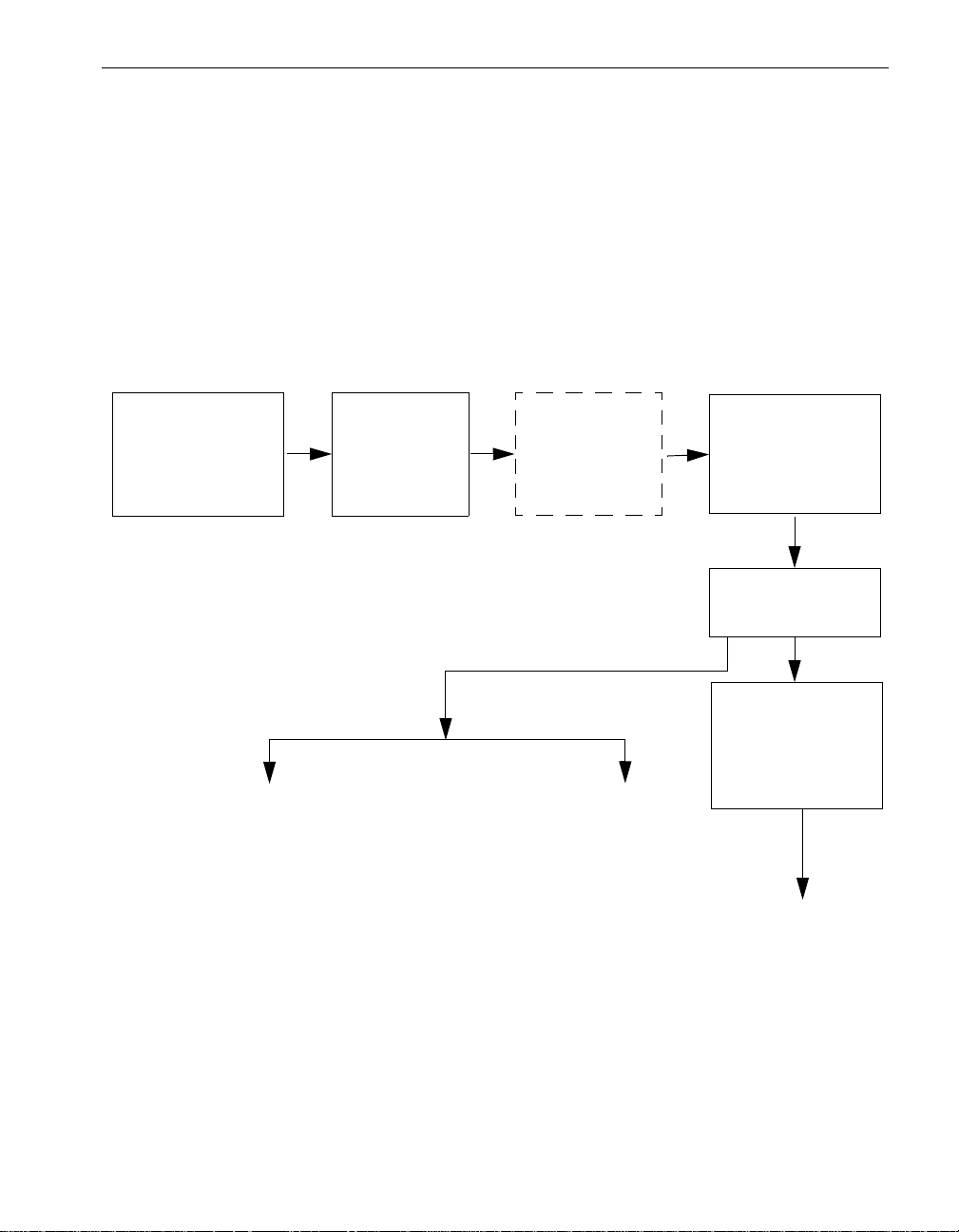
ftServer Manager Event Handling
As shown in Figure 2-1, when a hardware device fault or event occurs, the device’s
driver sends those events to the Express5800 /320Ma Policy service, which determines
whether the events are significant or not. Significan t events are forwarded to the Alarm
service for processing. The dotted lines around the Maintenance and Diagnostic
Service box in Figure 2-1 indicate that the service does not manage all devices. It does
manage, for instance, CPU elements, DIMMs, processor s, I/O elements, and PCI
adapters.
Figure 2-1. ftServer Manager Event Handling
Hardware Device
Event or Fault
Driver
Notification
ftServer
Maintenance
and
Diagnostics
Service
ftServer Manager Event Handling
Policy Service
Filters
Alarm Service
Forwards Event
VTMs
or
RAS Service
Event Log
Customer
(pager or email)
Call home
NEC Technical Support
ASN Connection Retry Cycle
After a failed attempt to connect with the ASN, the system will make repeated attempts
to call the ASN until it is successful. If your system is located in an area where North
American toll-free numbers cannot be used, this can result in costly phone bills. You
Express5800/320Ma System Features 2-7
Page 22

ASN Connection Retry Cycle
can adjust the parameters described in Table 2-3 to increase the time between phon e
calls, and thereby reduce the number of attempted calls.
If an attempt to establish an ASN connection fails, ftServer Manager can attempt to
send the alarm over the Internet if the Send Alarms By property is configured for
Internet backup. ftServer Manager also continues to attempt to establish an ASN
connection. All of the parameters in Table 2-3 work together to control how many
attempts ftServer Manager makes to establish the ASN connection. The y also control
the length of time between attempts. Table 2-3 shows the default values for these
parameters.
Table 2-3. Default Settings for Alarm Re-send Parameters
Parameter Default
Short Idle Time Between Re-sends 600 (10 minutes)
Short Idle Re-send Count 3 attempts
Medium Idle Time Between Re-sends 14400 (4 hours)
Medium Idle Re-send Count 6 attempts
Long Idle Time Between Re-sends 88000 (24 hours, 26 minutes, and
40 seconds)
Long Idle Re-send Count No limit on number of attempts
The following example illustrates the ASN connection retry cycle with default parameter
values:
Initial attempt to establish connection fails.
Retry 1: Wait 10 minutes, and then try again. This is the 1st 10-minute wait.
Retry 2: Wait 10 minutes, and then try again. This is the 2nd 10-minute wait.
Retry 3: Wait 10 minutes, and then try again. This is the 3rd and last 10-minute
wait.
Retry 4: Wait 4 hours, and then try again. This is the 1st 4-hour wait.
Retry 5: Wait 4 hours, and then try again. This is the 2nd 4-hour wait.
Retry 6: Wait 4 hours, and then try again. This is the 3rd 4-hour wait.
Retry 7: Wait 4 hours, and then try again. This is the 4th 4-hour wait.
Retry 8: Wait 4 hours, and then try again. This is the 5th 4-hour wait.
Retry 9: Wait 4 hours, and then try again. This is the 6th and last 4-hour wait.
Retry 10: Wait 24 hours, and then try again. This is the 1st 1-day wait.
ftServer Manager continues to make connection attempts every 24 hours.
2-8 Express5800/320Ma: Technical Reference Guide
Page 23

ASN Connection Retry Cycle
If an additional alarm condition occurs during one of the Medium Idle Time Between
Re-sends or Long Idle Time Between Re-sends periods, ftServer Manager interrupts
the current cycle. ftServer Manager then attempts to establish an ASN connection
according to the settings of the Short Idle Re-send Count and Short Idle Time Between
Re-sends parameters. If these attempts are not successful, ftServer Manager resumes
making attempts according to the settings of the Medium-Idle or Long-Idle Re-send
Count and Medium-Idle or Long-Idle Time Between Re-sends parameters.
For example, suppose that ftServer Manager fa iled to establish a call-home connection
and that the next attempt is scheduled to occur three hours from now, due to either a
24-hour or 4-hour wait period. If an add itional alarm condition occurs, ftServer Manager
immediately attempts to establish an ASN connection three times with a 10-minute wait
between attempts. If still unsuccessful, the original cycle resumes at the point it was
interrupted with the next dial attempt occurring three hours later.
Express5800/320Ma System Features 2-9
Page 24

ASN Connection Retry Cycle
2-10 Express5800/320Ma: Technical Reference Guide
Page 25

Chapter 3
ftSMC Component Properties and
Actions
This chapter describes a number of the properties and actions associated with ftSMC
system inventory components.
ftSMC Component Properties
Table 3-1 describes many of the properties of ftSMC system inventory components.
For component properties not described in the following table, use What’s this? Help
in ftSMC details pane for information.
Table 3-1. ftSMC System Inventory Component Properties
Property Description
ActiveCompatibilityFlag Specifies whether the I/O element is active (True) or inactive
(False). The active element is the one that contains the active
device of a pair of devices, the other of which is installed on the
inactive I/O element.
ActiveRDRPlex The address of the path that is the current active RDR plex.
3-
AdapterDeviceName Express5800/320Ma part number and description of PCI adapter.
ASN For Call-home Displays the numerical designation of the current active ASN
configuration. VTMs and ftSMC obtain the parameters for a call
home by reference to this property. The parameters in the active
ASN configuration are then used to establish a connection to the
active ActiveService Network (ASN), whether it is the NEC
Technical Support. The default active ASN configuration is 1. See
the Set as Active ASN action in Table 3-2.
AutoBringUpEnabled Brings a new CPU element in the system into service immediately if
this is enabled. The valid choices are True or False, with True
(enabled) as the default.
ftSMC Component Properties and Actions 3-1
Page 26

ftSMC Component Properties
Table 3-1. ftSMC System Inventory Component Properties (Continued)
Property Description
AutoBurnEnabled If enabled for a CPU element, matches a new CPU element’s BIOS
with that of the existing element when you insert a partner CPU
element that has a different BIOS version than the existing element.
The valid choices are True or False, with True (enabled) as the
default. Insert new elements only while the system is running. See
also Update Firmware in Table 3-2. You can check the BIOS
versions in ftSMC.
For a VTM, specifies if automatic burning is enabled. If so, the
existing firmware revision will be burned to a new VTM that is added
to the system. Set to false by default.
Availability The availability of the device. For the Express5800/320Ma
embedded 7174 SATA controller, possible states are running with
full power (value of 3), warning (4), test (5), degraded (10), power
save (13-15 and 17). See What’s this? Help in ftSMC for more
detail.
BackplaneCfg The storage enclosure’s backplane configuration (joined-bus or
split-bus).
BIOS: Version The BIOS version assigned by NEC Solutions (Amer ica), Inc.
BIOS: VendorVersion The BIOS version assigned by the BIOS vendor.
Brand A description of the type of processor in the CPU element.
Call-home Enable Determines whether the system is enabled to generate call-home
messages (True) or not (False). If this is disab led, the system does
not send any messages or system inventory reports to the ASN.
Enabled by default.
Call-home IP Address Displays the ASN IP address after the connection is made (for
example, 192.168.78.99); otherwise, it is a null value (0.0.0.0).
Call-home Licensed Indicates whether the system has a valid license to generate
call-home messages. Valid values are True or False.
Call-in Enable Indicates whether VTM accepts calls from the ASN. If this is
disabled, VTM does not answer the telephone. Enabled by default.
Valid values are True (enabled) or False (disabled).
Capacity The data capacity of a physical disk drive (or plex in RDR) or of a
virtual RDR disk, usually expressed in gigabytes (GB).
Caption A short textual description of the object.
Chipset: BusNumber[1] The numerical designation of the bus.
Chipset: BusWidth[1] The data width of the bus in bits.
3-2 Express5800/320Ma: Technical Reference Guide
Page 27

ftSMC Component Properties
Table 3-1. ftSMC System Inventory Component Properties (Continued)
Property Description
Chipset: Mhz66Capable[1] Indicates whether the PCI bus operates at 66 MHz (True) or not
(False).
Chipset: NumberOfBuses The number of buses.
Chipset:
TotalSystemMemoryMb
Chipset: Type The type of chipset used in the CPU element.
City City or town where your company is located.
Class Code The type of device or adapter in this location.
Company Name The name of the company that owns this system.
ConfigData Specifies whether ESCD data should be cleared on the next reboot
ConfigManagerErrorCode The Win32Configuration Manager error code. Use What’s this? help
ConfigManagerUserConfig Indicates whether the device is using a user-defined configuration.
ConfigState State information of an RDR virtual disk plex. An RDR disk can be
Connection Status Status of the ASN connection. Values are Off, On, and In process.
Connection Timeout Maximum amount of time, in seconds, that ftServer Manager waits
Total amount of system memory.
of the system.
in ftSMC for details.
Configured/Unconfigured. If it is configured, it could be active or
inactive, imported or deported.
for a system to make each dial-out attempt. Default is 180 seconds
(3 minutes). When a system attempts to make a connection to the
ASN, ftSMC waits a period of time, defined by Transmit Timeout, for
the system to signal the status of the connection.
Country Country where your company is located.
CpuBringUpPolicy Specifies whether CPU bringup is enabled, disabled (deferred) and
simplex CPU operation is allowed, or disabled and simplex CPU
operation is not allowed. This property is set by means of the
Schedule CPU BringUp Options action, which is described in
Table 3-2.
CreationClassName The name of the class or the subclass used in the creation of an
instance. When used with the other key properties of this class, this
property allows all instances of this class and its subclasses to be
uniquely identified.
ftSMC Component Properties and Actions 3-3
Page 28

ftSMC Component Properties
Table 3-1. ftSMC System Inventory Component Properties (Continued)
Property Description
Current Count The current MTBF value for a device. A 0 or Unknown value means
that the device has not failed often enough to calculate MTBF data.
CurrentReading Specifies the current value of a sensor. Depending on the sensor,
values are in deg re es Celsius (
o
C) for temperature sensors,
millivolts (mV) for voltage sensors, revolutions per minute (rpm) for
fan speed sensors, or milliamperes (mA) for current sensors.
Customer Contact Name Contact person in your company who is responsible for the system.
Customer Email Email address of your company contact.
Customer Pager Pager number of your company contact.
Customer Phone Telephone number of your company contact.
DebugFlags:Irql
DebugFlags:Thread
When these flags are enabled, debug trace messages printed using
these flags will be logged.
DefaultGateway For systems equipped with VTMs. The IP address of the default
gateway used for traffic that goes to a network for which the adapter
has no route (for example, to NEC Technical Support or other
service representative, in communication from the system to the
adapter).
Defer Bringup Defers the automatic return-to-service of the CPU element (CPU
bringup) to a more convenient time.
Description A description property that helps you identify a particular ASN
configuration.
DeviceID An address or other identifying value that uniquely names a logical
device.
DevicePath[n] A string of slash-separated De viceIDs that sho ws the relationship of
a device within a hierarchical ordering of devices. The DevicePath
property shows what other devices a particular device is connected
to, or is a child of.
DevicePathID Device identifier used to physically locate hardware components
within a system. A DevicePathID is a string of decimal numbers
such as 10/5/0/2.
For a virtual disk, the DevicePathID does not indicate a hardware
component, but instead identifies the virtual disk to system
management software.
DiagScreen Specifies whether the BIOS Diagnostics screen should be displayed
during the boot process.
3-4 Express5800/320Ma: Technical Reference Guide
Page 29

Table 3-1. ftSMC System Inventory Component Properties (Continued)
Property Description
ftSMC Component Properties
Diag Status:
FailingTestNumberr
Diag Status:
NumberOfFailedTests
Diag Status: TimeOfLastRun Date and time when diagnostics most recently ran.
DiagnosticStatus The VTM diagnostic status.
Dial-in Password Password used to authenticate a dial-in user name.
Dial-in User Name Dial-in user name used to identify the ASN dialing in. After the
Drive The drive letter, including the colon, of the file.
DriverName The driver file name of the device.
DriverServiceName Name of the service supporting this driver.
DriverVersion Version number of the driver.
DumpNumberOfFilesToSave Sets the number of dump files to save to disk for a system dump.
If diagnostic test(s) failed, the number of the diagnostic test(s) that
failed.
The number of errors encountered. See the system ev ent log for a
description of the errors.
system authenticates the name, the system hangs up and dials the
ASN.
For example, if this value is 2, the last two dump files
(Memory0.dmp and Memory1.dmp) are saved and the third dump
file overwrites the first. Thus, you need to reserve disk space of the
size of memory times this number for the dump files. The valid
range is 1 to 5, and the default is 2.
ftSMC Component Properties and Actions 3-5
Page 30

ftSMC Component Properties
Table 3-1. ftSMC System Inventory Component Properties (Continued)
Property Description
DumpQuickEnabled Controls the operation of a system crash dump. All of the system
memory may be dumped, depending on what you specify for the
type of memory dump. Therefore, you need to reserve disk space
for the dump. See also DumpNumberOfFilesToSave. The valid
choices are True or False, with True (enabled) as the default.
If DumpQuickEnabled is disabled or if the CPU element is in
simplex mode, the normal Windows dump mechanism is used.
If DumpQuickEnabled is enabled and CPU elements are in duplex
mode, one CPU element is held in the Broken state and the
remaining element(s) will be rebooted. After the system is running
again, the broken element is dumped and returned to servic e if
AutoBringUpEnabled is enabled.
If DumpQuickEnabled is disabled and CPU elements are in duplex
mode, the system will attempt to obtain both kinds of dumps; that is,
one CPU is held in the Broken state, and a normal Windows dump
is initiated. Upon reboot, the Broken element is dumped and
returned to service. If two dumps are produced, the normal
Windows dump will be deleted, as it is redundant.
DumpsToSave Specifies the maximum number of VTM memory dumps to retain.
The default is 1. Memory dumps are 16 MB. If DumpsToSave is
specified as 0, no dumps are created. The dump occurs if VTM
crashes. The dump is saved to %SystemRoot% with the file name
smmmemx.dmp, where x is the dump number derived from
LastGoodDump and DumpsToSave.
Duplex Describes how the Ethernet adapter sends and receives packets
when connected to the Twisted-Pair Ethernet (TPE) connectors.
Settings are: Auto (default) - negotiate with the switch or hub to
determine the best mode. Half - half duplex performs one operation
(either send or receive) at a time. Full - full duplex sends and
receives packets at the same time.
ECC Info: HardErrors Number of uncorrectable errors detected.
ECC Info:
IntermittentHardErrors
ECC Info: SoftErrors Number of correctable errors detected.
ECC Info: ThresholdExceeded Indicates whether an error threshold has been exceeded. If this
ECC Info:TotalEccErrors Number of ECC errors detected.
3-6 Express5800/320Ma: Technical Reference Guide
Number of correctable errors reported for the same bit.
property is false, nonzero counts should not be considered errors.
Page 31

ftSMC Component Properties
Table 3-1. ftSMC System Inventory Component Properties (Continued)
Property Description
EccMinutesToComplete Sets the time, in minutes, to complete a single check (read followed
by write if an error is detected) of all memory. The valid range is 10
to 10,080 minutes (7 days), and the default is 1440 minutes (1 day).
EccThreshold Sets the thre shold number of errors that sends an ECC call-home
message. The range is 19 to 512 errors, and the default is 128.
Enable Bringup Returns a CPU element to automatic return-to-service mode.
Enabled If True, NEC Technical Support or your service representative
designated by this ASN is allowed to dial in, and the ASN
referenced in the ASN For Call-home property is allowed to call
home. Valid values are True (enabled) or False (disabled). The
default is False (disabled).
Encrypt Http Over Internet If enabled, encrypts data when sending an alarm over the Internet.
Disabled by default. Valid values are True (enabled) or False
(disabled).
Encrypt Ignoring Unknown CA Indicates whether the system should accept an SSL certificate that
was issued by an untrusted certificate authority’s root certificate. If
true, accepts unknown CA when sending an encrypted alarm over
the internet.
EventMessageBufferEnabled Enables (True) or disables (False) the event message buffer.
EventMessageBufferFullInterr
uptEnabled
FirmwareRevision Displays the firmware revision of the BMC.
ftGateway Group ID Defines a particular ftGateway group.
ftGateway Group Name The customer-supplied name of an ftGateway group.
ftGateway IP Addresses[1] Specifies one of two network IP addresses that the gateway
ftGateway IP Addresses[2] Specifies one of two network IP addresses that the gateway
ftGateway Password The customer-specified password required for communications
Express5800/320Ma Release The Express5800/320Ma System Software release number.
Express5800/320Ma Version The Express5800/320Ma System Software version designation.
ftSMC Component Properties and Actions 3-7
Enables (True) or disables (False) the event message buffer full
interrupt.
machine uses to communicate with other members of the ftGateway
group.
machine uses to communicate with other members of the ftGateway
group.
between ftGateway group members.
Page 32

ftSMC Component Properties
Table 3-1. ftSMC System Inventory Component Properties (Continued)
Property Description
FwVersion The version of the firmware running on an VTM.
GlobalRdrPlexLoadBalancing An RDR property that manages read-road balancing globally.
GlobalResyncPriority Specifies the relative priority (Low, Normal, or High) of the
resynchronization process to other processes in the system.
Default: Normal.
Group Type The type of system management modules (SSMs) in the ftGateway
group, namely, VTMs.
Heartbeat Interval This property is the time, in seconds, that a slave machine in an
ftGateway group wa its before issuing another heartbeat signal. The
default value is 900 seconds (15 minutes).
HighResynchPriorityMbs The high value for I/O bandwidth to disk, a portion of which will be
used for RDR disk resynchronization operation. The default value of
this property is 35Mbps.
Host XML Port Number The XML port number for the TCP server running on the host. VTMs
communicate with the host by sending XML commands to this
server.
HTTP Absolute Path The path of the HTTP object to which to send an alarm message.
For example, if alarm messages are posted to URL
http://callhome/callhomeservice.asp, this field has the va l u e
/callhome/callhomeservice.asp.
Http over internet Enabled If enabled, ftServer Manager attempts to send messages using
HTTP over the Internet after failing to establish a connection to the
ASN through the external modem. Enabled by default. Valid values
are True (enabled) or False (disabled).
IDPROM: ArtworkRevision This type of PROM, located on boards manufactured by NEC
Solutions (America), Inc, contains board identification information.
IDPROM: ECOLevel This type of PROM, located on boards manufactured by NEC
Solutions (America), contains board identification information.
IDPROM: EEPROMVersion This type of PROM, located on boards manufactured by NEC
Solutions (America), contains board identification information.
IDPROM:
MinPartnerECOLevel
IDPROM: ModelDesc This type of PROM, located on boards manufactured by NEC
3-8 Express5800/320Ma: Technical Reference Guide
This type of PROM, located on boards manufactured by NEC
Solutions (America), contains board identification information.
Solutions (America), contains board identification information.
Page 33

ftSMC Component Properties
Table 3-1. ftSMC System Inventory Component Properties (Continued)
Property Description
IDPROM: ModelName This type of PROM, located on boards manufactured by NEC
Solutions (America), contains board identification information.
IDPROM: SerialNumber This type of PROM, located on boards manufactured by NEC
Solutions (America), contains board identification information.
Internet Call-in Poll Interval The interval, specified in seconds, that the SMM waits between
polling Hub machines to find out if call-in over the Internet is
needed. The default value is 300 seconds (5 minutes).
Internet Corruption Re-send
Count
Internet HTTP Proxy Address A list of the HTTP proxy server addresses (host:port) that ftServer
Internet HTTP Proxy
Password
Internet HTTP Proxy User
Name
Internet HTTP Server Address The HTTP server address (host:port) that ftServer Manager uses to
Internet Tunnel Server
Address
The number of re-send attempts ftServer Manager will make before
removing the alarm, when an Internet corruption error is received
while sending alarms by Internet only.
Manager uses to send alarm messages over the Internet in a
space-delimited string (for example, myproxy1:8080
myproxy2:8080). Set to empty if no proxy is required.
The password to access the proxy server.
The user name to access the proxy server.
send alarm messages over the Internet. The host name may be
either a domain name (for example, www.necsam.com) or an IP
address in ASCII dotted-decimal format (for example,
192.52.248.194). The port number is optional (by default, HTTP is
80 and HTTPS is 443).
Tunnel server address (<host>) that SMM uses for dial-in over the
Internet. The host name may be either an FQDN
(inettunel.ecacsupport.com) or a dotted-decimal IP
(134.111.1.21). This address should be equal to the CN field of the
Web server certificate (use inettunel.ecacsupport.com by
default).
IsPrimary Identifies the primary VTM.
LastGoodDump For systems equipped with VTMs. Specifies the memory dump
number of the last known good dump.
LED State: Yellow
LED State: Red
LED State: Green
LED State: White
ftSMC Component Properties and Actions 3-9
Indicates the state of an LED in the system (On, Off, NotPresent, or
Cycle). See the operation and maintenance guide for your system
for a description of the meanings of th e LED s.
Page 34

ftSMC Component Properties
Table 3-1. ftSMC System Inventory Component Properties (Continued)
Property Description
Limit of Event Log Entries The maximum number of event log entries to include in any
message. By default, if the specified interval has more than 256
entries in either the system or the application log, the last 256
entries are sent as part of the message.
Line1 Contains the text on the top line of the front panel LCD.
Line2 Contains the text on the bottom line of the front panel LCD.
LinkDataRate The current signalling rate of the link.
LinkProtocol The storage command protocol running on the link.
Long Idle Re-send Count The number of re-send attempts, separated by Long Idle Time
Between Re-sends, that ftServer Manager will make before
dropping the current alarm message.
Long Idle Time Between
Re-sends
The long idle time, in seconds, between attempts to re-send an
alarm. After a number, defined by Medium Idle Time Between
Re-sends, of unsuccessful attempts to send an alarm message,
ftServer Manager waits this long before it attempts to re-send the
alarm. After a number of unsuccessful attempts, defined by Long
Idle Re-send Count, ftServer Manager will quit attempting to send
the oldest alarm message and move to the next one in the alarm
queue.
LowerThresholdCritical Threshold values specify the ranges for determining whether the
monitored component is operating under normal, noncritical, critical,
or fatal conditions. Depending on the sensor, values are in degrees
Celsius (
o
C), millivolts (mV), revolutions per minute (rpm), or
milliamperes (mA).
LowerThresholdFatal Threshold values specify the ranges for determining whether the
monitored component is operating under normal, noncritical, critical,
or fatal conditions. Depending on the sensor, values are in degrees
Celsius (
o
C), millivolts (mV), revolutions per minute (rpm), or
milliamperes (mA). This property is not configurable and attempting
to change it will display the value of Not Set.
LowerThresholdNonCritical Threshold values specify the ranges for determining whether the
monitored component is operating under normal, noncritical, critical,
or fatal conditions. Depending on the sensor, values are in degrees
Celsius (
o
C), millivolts (mV), revolutions per minute (rpm), or
milliamperes (mA).
LowResynchPriorityMbs The low value for I/O bandwidth to disk, a portion of which will be
used for RDR disk resynchronization operation. The default value of
this property is 5Mbps.
3-10 Express5800/320Ma: Technical Reference Guide
Page 35

ftSMC Component Properties
Table 3-1. ftSMC System Inventory Component Properties (Continued)
Property Description
LunFlushInterval Interval, in minutes, between flushes of the disk write cache. Default
is 0, disabled.
LunVerifyInterval Specifies the frequency with which information on physical disks
that are configured as mirrors in an RDR virtual disk are compared
to each other. Default: 10800 minutes (7 days)
MachineCheckThreshold Sets the threshold number of errors that sends a Correctable
Machine Check call-home message. The system keeps a record of
the number of Correctable Machine Check errors detected per CPU
element and whether the threshold has been exceeded. Look at
individual processors to see which ones are experiencing problems.
Manufacturer The manufacturer of the device.
MCA Info:
ThresholdExceeded
Medium Idle Re-send Count The number of re-send attempts, separated by Medium Idle Time
Medium Idle Time Between
Re-sends
Member Status Identifies whether a system is a member of an ftGateway group or
Member Status Confirm Provides feedback on the Join ftGateway Group action, which is
MemCheckRate S ets the rate at which the driver checks memory. The rate is a
Indicates if the configured error threshold for Correctable Machine
Check errors, has been exceeded.
Between Re-sends, that ftServer Manager will make before moving
to the long idle interval.
The medium idle time, in seconds, between attempts to re-send an
alarm. After a number, defined by Short Idle Re-send Count, of
unsuccessful attempts to send an alarm message, ftServer
Manager waits this long before it attempts to re-send the alarm.
After a number of unsuccessful attempts, defined by Medium Idle
Re-send Count, ftServer Manager will wait the amount of time
defined by Long Idle Time Between Re-sends before attempting to
re-send the alarm message.
not, and if it is a member, whether it is a gateway or slave machine.
The default value is Non-member.
described in Table 3-2. It is set to Confirm Pending after executing
the Join ftGateway Group action. It is then set based on the
feedback status from the gateway adapter. The default value is Not
Applicable.
number from 0 to 9, where 0 is the slowest rate and 9 is the fastest.
The default is 5. See Perform Memory Check, which is described
in Table 3-2.
Messages[n] Contains the text displayed on the front pa nel LCD.
Model The device’s model number.
ftSMC Component Properties and Actions 3-11
Page 36

ftSMC Component Properties
Table 3-1. ftSMC System Inventory Component Properties (Continued)
Property Description
ModelDescription or
The VTM board description.
ModelDesc
ModelName The Express5800/320Ma system name as stored in the system ID
PROM. For VTMs, the VTM OEM product number.
Modem Check Interval The number of seconds that the system waits between checking
that the modem attached to the system is functional and checking
that a dial tone exists on the phone line. If this value is set to zero,
modem checks are disabled. The default is 3600 seconds (1 hour).
Modem Country Code Telephone calling code for the country where the modem is located
(for instance, 1 = USA, 44 = United Kingdom). Select the country
from the drop-down list.
Modem Post-Init Commands Contains addition al mode m initialization string commands that are
sent to the SMM modem after the default initialization string is sent.
Modem Pre-Dial Commands Contains additional modem dial commands that are sent to the
SMM modem immediately prior to the sending of a dial command.
MTBF: Current Current MTBF in seconds. A value of un known (0 ) indicates that the
device has not failed enough times for an MTBF to have been
calculated.
MtbfFaultLimit Defines the number of times certain errors can occur before the
system sends threshold events that generate alarms.
MTBF: NumberOfEvents Total number of faults for a component.
MTBF: Threshold Threshold, in seconds, below which the component will not be
automatically brought back into service when it fails. The default is
600 seconds, and the range is 600 seconds to 4,294,967,295
32
(2
-1) seconds.
MTBF: TimeOfLastEvent Date and time of the last fault on a component.
MTBF: TimeOfLastFault Time at which the device last failed.
MTBF: Type Defines how the threshold value is used when a device fails.
Normally Type is set to Use Threshold, which indicates that the
threshold value is used to determine whether to automatically bring
the device back into service. The NEC Technical Support can set it
to Never Restart or Always Restart.
Name In ASN, the name or designation of each ASN Configuration node.
In relation to the SATA embedded adapter, defines the label by
which the object is known. When subclassed, the Name property
can be overridden to be a Key property.
3-12 Express5800/320Ma: Technical Reference Guide
Page 37

ftSMC Component Properties
Table 3-1. ftSMC System Inventory Component Properties (Continued)
Property Description
NegativeGoingHysteris A value added to a reading to determine if a threshold event has
cleared. A value of 0 means that the event clears after the reading
drops to one less than High Warning or Critical Threshold.
NormalResynchPriorityMbs The middle value for I/O bandwidth to disk, a portion of which will be
used for RDR disk resynchronization operation. The default value of
this property is 20Mbps.
Notify Email Address The customer email address or addresses to send an email to when
an alarm occurs (for example, administrator@company.com). Use a
semicolon to separate multiple addresses (for example,
admin1@company.com;admin2@company.com). The length of all
addresses and their separators in this field must be less than 300
characters.
Notify Final Delay The amount of time, in minutes, for the User Notification processes
to wait after sending email, before sending another one, to allow for
multiple alarms to be aggregated and sent at the same time. The
default is 10 minutes.
Notify Initial Delay The amount of time, in minutes, for the User Notification processes
to wait before sending email in order to allow for multiple alarms to
be sent at the same time. The default is 1 minute.
Notify Pager Number The customer pager number to send a page to when an alarm
occurs.
Notify Proxy Bypass If the proxy server can be bypassed for local addresses, set this to
“local”; otherwise, leave blank.
Notify Proxy Server The server and port name of the customer proxy server in the
format server:port (for example, proxy.customer.com:1234).
Notify Send Old Messages If True, send any unsent messages at startup. If False, delete any
previously unsent messages.
Notify SMTP Auth Mode Authentication mode for the customer SMTP ser ver. Can be either
Anonymous (no authentication required) or Basic (need to supply a
user name and password).
Notify SMTP Password The password for authentication with the customer SMTP server.
Used only if Notify SMTP Auth Mode is set to Basic.
Notify SMTP Server SMTP server to use to notify a customer by email of alarm
conditions (for example, mailhub.company.com).
Notify SMTP User Name The user name for authentication with the customer SMTP ser ver.
Used only if Notify SMTP Auth Mode is set to Basic.
ftSMC Component Properties and Actions 3-13
Page 38

ftSMC Component Properties
Table 3-1. ftSMC System Inventory Component Properties (Continued)
Property Description
Notify SNPP Port The port number used by the Simple Network Paging Protocol
(SNPP) server for sending a page. Default is port 0.
Notify SNPP Server The IP address of the SNPP server used to send pager messages.
Number of Faults Total number of times the device has failed.
Num of Missed Polls Defines how many polls can be missed between a slave machine
and the ftGateway machine before the slav e machine is determined
to be offline.
Number of Retries Number of times that the system attempts to dial each number in
the list of Phone Numbers when attempting to contact NEC
Technical Support or your service representative. A value of 1 (the
default) indicates that the system calls each phone number only
once. A value of zero (0) is invalid.
OEMManufacturer The original manufacturer of the device.
OEM0Enabled Defined by OEM or system integrator. Do not change the default
setting (False ) of this property.
OEM1Enabled Defined by OEM or system integrator. Do not change the default
setting (False ) of this property.
OEM2Enabled Defined by OEM or system integrator. Do not change the default
setting (False ) of this property.
OnlineCpuPriority For CPU elements only. The priority at which the CPU is operating.
Supported values are High and Medium. The priority of other
elements is adjusted accordingly as follows:
If the priority of the specified element is increased, the element with
the same priority has its priority decrea sed.
If the priority of the specified element is decreased, the element with
the same priority has its priority increa sed.
Op State: Reason The reason a component is in a particular operational state.
Op State: Reason
None
Op State: Reason
Below MTBF
Op State: Reason
Diagnostics Failed
Op State: Reason
Hardware Incompatible
Indicates that there is no reason associated with the current state.
The current MTBF is below the MTBF threshold specified for this
component.
This component failed diagnostic testing.
The component hardware is incompatible with the online system
hardware.
3-14 Express5800/320Ma: Technical Reference Guide
Page 39

Table 3-1. ftSMC System Inventory Component Properties (Continued)
Property Description
ftSMC Component Properties
Op State: Reason
Bringup Failed
Op State: Reason
Parent Broken
Op State: Reason
Media Disconnect
Op State: Reason
Firmware Burn Fail
Op State: Reason
Firmware file not found
Op State: Reason
Firmware file error
Op State: Reason
Firmware PROM error
Op State: Reason
Autoburn Disabled
Op State: Reason
Primary
Op State: Reason
Secondary
The driver did not bring the element online.
Parent device of this device is broken (for example, the parent I/O
element for this adapter is broken).
Simplex state was entered because a cable was unplugged.
Failed to update the BIOS.
The entered firmware file path is either incorrect or the file does not
exist.
Could not read the firmware file.
Could not write to the firmware file.
Cannot match a new element’s BIOS with that of the existing
element. See AutoBurnEnabled in this table.
With duplex devices, this indicates that the specific device is primary
in the pair.
With duplex devices, this indicates that the specific device is
secondary in the pair.
Op State: Reason
Parent Empty
Op State: State Operational state of a component.
Op State: State
Broken
Op State: State
Dumping
Op State: State
Diagnostics
Op State: State
Diagnostics passed
ftSMC Component Properties and Actions 3-15
The device above this device in the hierarch y is not present or does
not have power.
A component has a problem; an associated reason (see Op State:
Reason) describes the problem. This is a terminal state; some user
action must occur to change this state . User actions that cause a
transition out of the Broken state include the Initiate BringUp and
Initiate BringDown actions, and removing the component. Both of
these actions are described in Table 3-2.
A CPU element is recovering crash dump information.
A component is running diagnostics.
A component has passed diagnostics.
Page 40

ftSMC Component Properties
Table 3-1. ftSMC System Inventory Component Properties (Continued)
Property Description
Op State: State
Empty
Op State: State
Initializing
Op State: State
Firmware update
Op State: State
Firmware update complete
Op State: State
Removed
Op State: State
Shot
Op State: State
Syncing
Op State: State
DeviceReady
Op State: State
Stopped
Op State: State
StopPending
The component slot does not have a component present, or the
component does not have power.
Preparing a device to be brought online.
Board firmware code is being updated.
Board firmware code is updated.
A component is present in the slot, but main power is not turned on
and the component is out of service.
A component has an error and was taken out of service by system
logic. When in this state, the component is electrically isolated from
the rest of the system.
A CPU element is synchronizing with the online element.
Driver notified of a given device and is initializing the device. Applies
to components that the PnP Manager can manage.
Driver stops the component; the component is no longer running.
Applies to components that the PnP Manager can manage.
Waiting for a Stop or Stop Cancel request. Applies to components
that the PnP Manager can manage.
Op State: State
RemovePending
Op State: State
SurpriseRemoval
Op State: State
Simplex
Op State: State
Duplex
OPROMScanTime Specifies the maximum time that PCI Option ROM processing can
3-16 Express5800/320Ma: Technical Reference Guide
Waiting for the softw are remo v al that precedes the physical remo v al
of the component. Applies to components that the PnP Manager
can manage.
A device was unexpectedly removed from the machine and is no
longer available f or I/O. Applies to components that the PnP
Manager can manage.
A component is online and has no partner; it is not safe to remove
this component. Applies to components that can be partnered.
The component is online and is running in lockstep with one other
component. This component is safe to remove. Applies to
components that can be partnered.
take before the system is considered hung.
Page 41

ftSMC Component Properties
Table 3-1. ftSMC System Inventory Component Properties (Continued)
Property Description
OsBootTime Specifies the maximum time that OS boot process processing can
take before the system is considered hung.
Owner Indicates the owner of the modem.
Pager Final Delay The amount of time, in minutes, for the Alarm Service to wait after
sending a page, before sending another one. This allows one page
to be sent for multiple alarms occurring in a timespan. The default is
10 minutes.
Pager Initial Delay The amount of time, in minutes, for the Alarm Service to wait after
sending a page, before sending another one, to allow for multiple
alarms to be aggregated and sent at the same time.
PartNumber The VTM adapter part number.
Partner: DevicePath Device identifier that locates the component that is the partner of
this component if this component is operating in fault-tolerant mode
and Partner: PartnerCou nt is not 0. See DevicePathID.
Partner: PartnerCount Number of components of this type that are operating in a
fault-tolerant mode: simplex (0), or duplex or DMR (1). Ethernet
adapters must be partnered. A maximum of two adapters can be
partnered by the Port Duplex driver.
Partners Specifies the number of partner components a component has
when operating in a fault-tolerant mode: simplex (0) or duplex (1).
For example, a CPU element with one partner will have a value of
Partners[1].
PCI ASIC A set of properties (BusNumber, DeviceNumber, LogicRevision,
Version) that provide information about the PCI ASIC in the I/O
element.
PCIEnumerationTime Specifies the maximum time that PCI enumeration can take before
the system is considered hung.
PCIFunctionNumber Function’s PCI function number.
Phone Numbers Telephone numbers of NEC Technical Support or your service
representative. The numbers can be from 10 to 120 characters long
and they are in text-character form at (for example, 9785551234).
When attempting to connect to the ASN, a system dials each phone
number the number of times defined by Number of Retries.
ftSMC Component Properties and Actions 3-17
Page 42

ftSMC Component Properties
Table 3-1. ftSMC System Inventory Component Properties (Continued)
Property Description
PlexEpochValid Specifies the maximum number of minutes you can keep a disk out
of the system without causing a full resynchronization when the disk
is returned to the system. A value of 0 disables any
resynchronization of the disk after a disk is removed from and
returned to the system. Default: 15 minutes.
PnpClass Type of function as reported by Plug and Play.
PnpDescription Description as it appears in Device Manager.
PnpDeviceID Plug and Play device ID, including the Instance ID.
PnpDeviceLocation Location of the function as reported by Plug and Play.
PnpManufacturer Manufacturer of the function as reported by Plug and Play.
Polling Interval The interval, specified in number of seconds, that the gateway VTM
waits between polling slave machines in the ftGateway group.
Polling determines if a slave is online or offline. The default value is
1800 seconds (30 minutes).
PollInterval The interval, specified in number of seconds, at which the SES
driver monitors the storage enclosure for device faults and removals
by polling the SES device. The def ault poll interval is 3 seconds, and
the valid range is 1 to 10 seconds. Do not change the default value .
PositiveGoingHysteris A value subtracted from a reading to determine if a threshold event
has cleared. A value of 0 means that the event clears once the
reading rises to one more than Low Warning or Critical Threshold.
PowerState Indicates whether power is applied to the modem slot.
PPP Password Password used to authenticate the system to the ASN when the
system calls home or when a call back is made to the system. See
the Express5800/320Ma ActiveService Network Configuration
Guide.
Preserve Alarm Whether or not to preserve alarms after they are transmitted. False
(do not preserve) by default. See Alarm Directory in this table.
PreTimeoutInterrupt If enabled, BMC generates the selected interrupt a fixed interval
before the watchdog timer expires. This property can take a value of
NMI, SMI, MessagingInterrupt, or None.
PreTimeoutInterval The number of seconds that the PreTimeoutInterrupt is issued
before the timer expires.
Processing Rate Sets the speed at which the Policy Service processes received
events. This property can take a value of Normal, Low, or Very Low.
3-18 Express5800/320Ma: Technical Reference Guide
Page 43

ftSMC Component Properties
Table 3-1. ftSMC System Inventory Component Properties (Continued)
Property Description
PwrDownBrokenCpuEnabled When a CPU element transitions to the Broken state, the system
powers it down if this property is enabled (True). The default is
enabled (True).
PwrDownBrokenIoEnabled When an I/O element transitions to the Broken state, the system
powers it down if this property is enabled (True). The default is
enabled (True).
RdrLunLoadBalancing Load balancing policy for this virtual disk. Default is On (enabled).
ReadingTime For storage enclosures equipped with environmental sensors. The
date and time when the current reading from a storage enclosure
sensor was taken.
ReceiveMessageQueueInterr
uptEnabled
RegistryPath Location in the HKEY_LOCAL_MACHINE Registry key.
RevisionID Chipset revision incremented when vendor updates chipset.
SELTime The time used by the system event log. This value is set by the
Send Alarms By Defines whether call-home alarms will be sent by VTM adapter only ,
Serial Number The system serial number as stored in the system ID PROM. Filled
Short Idle Re-send Count The number of re-send attempts, separated by Short Idle Time
Short Idle Time Between
Re-sends
Enables (True) or disables (False) the receive message queue
interrupt.
Synchronize SEL date and time with System action, which is
described in Table 3-2.
the Internet only, VTM adapter with Internet backup, or the Internet
with VTM adapter backup.
in automatically.
Between Re-sends, that ftServer Manager will make before moving
to the medium idle interval.
The short Idle time, in seconds, between attempts to re-send an
alarm. After an unsuccessful attempt to send an alarm message,
ftServer Manager waits this long before it attempts to re-send the
alarm. After a number of unsuccessful attempts, defined by Short
Idle Re-send Count, ftServer Manager will wait the amount of time
defined by Medium Idle Time Between Re-sends before attempting
to re-send the alarm message
Site Heartbeat Granularity The granularity of the site heartbeat interval. 0 = days, 1 = minutes.
Site Heartbeat Interval The interval between site heartbeat alarms. Minimum interval =
10 minutes; maximum = 1 year; 0 = disabled.
ftSMC Component Properties and Actions 3-19
Page 44

ftSMC Component Properties
Table 3-1. ftSMC System Inventory Component Properties (Continued)
Property Description
Site Heartbeat Next Due The coordinated universal time (UTC) at which to expect the next
site heartbeat alarm.
Site Heartbeat Time Due Specifies the time of day for the initial site heartbeat alarm (24-hour
clock).
Site ID An Express5800/320Ma system identification code supplied by
NEC Solutions (America), Inc. You can obtain this code from a label
that is affixed to the system.
SizeMb The memory capacity of a DIMM, in megabytes.
SMM Admin Enable Email Enables the sending of VTM email alerts.
SMM Admin ID User name for the administrator account on the VTM.
SMM Admin Password Password for the administrator account on the VTM.
SMM Admin Dialback Number The phone number you use to dial in to the VTM adapter. After you
dial in and are authenticated as the administrator, the VTM hangs
up the connection and dials the dialback number to reestablish the
connection.
SMM ASN Hub ID User name for the ASN hub account on the VTM.
SMTP Forwarding The DNS name or IP address of an SMTP server. Messages sent to
the SMTP server will be forwarded to this server.
SNMP Community A filter for incoming SNMP messages and outgoing SNMP traps.
SMTP Server Enabled Set to true if the SMTP server should be started; otherwise, false.
SMTP Server IP The IP address of your email server.
SMTP Server IP 1-7 The IP addresses of the SNMP servers that receive VTM SNMP
traps.
SMTP Server Port TCP port number the SMTP server listens to.
SMM ASN Hub Password Password for the ASN hub account on the SSM.
SPPData ftSMC displays the Serial Presence Detect data (SPDData)
properties for the CPU element DIMMs. Serial Presence Detect
(SPD, device detection over a serial bus) is an enhanced presence
detection method that uses an EEPROM to store the module
timings and configuration, and the manufacturer's data. Presence
detection is a means of identifying a memory chip to the memory
controller logic. The NEC Technical Support or your service
representative uses this information to troubleshoot system memory
problems.
3-20 Express5800/320Ma: Technical Reference Guide
Page 45

ftSMC Component Properties
Table 3-1. ftSMC System Inventory Component Properties (Continued)
Property Description
Startup Time Number of seconds that the Policy Service waits for the system to
reach a quiescent state after booting.
State State, province, or other political entity where your company is
located.
Status Provides the status of a system inventory component.
StatusLEDColor Provides the state of the Status LED.
StorageProcessor The type of processor in the attached storage system.
StorageSerialNumber The serial number of the attached storage system.
StorageType The product family name of the attached storage system.
Support Phone Telephone number (1-866-269-1239) that you call to reach NEC
Technical Support or your service representative. This number is for
information only, as ftServer Manager does not use this number.
You should make a note of this telephone number in the event you
need support and your system is not functioning.
Street[1] Field containing the address (street, department, mail stop, PO box,
and so on) where your company is located.
Street[2] A second field containing the address (street, department, mail
stop, PO box, and so on) where your company is located.
SubNetMask For systems equipped with VTMs. A 32-bit structure that tells
TCP/IP which bits in a given address specify the network ID and
which specify the subnetwork ID (for example, 255.255.255.0).
SubsystemID ID of board among boards from vendor with the same chipset.
SubSystemVendorID PCI SIG-assigned ID to uniquely identify PC board vendor.
SummaryScreen Specifies whether the Summary screen should be displayed before
Windows is started.
System Email Address The email address to be used in the “From” field of a user
notification alarm message (for example,
machine4@company.com).
SystemEventLoggingEnabled Enables (True) or disables (False) the logging of events to the
system event log.
System: IDPROM:
ArtworkRevision
ftSMC Component Properties and Actions 3-21
The artwork revision of a board. Board identification information is
stored in IDPROM on boards manufactured by NEC Solutions
(America).
Page 46

ftSMC Component Properties
Table 3-1. ftSMC System Inventory Component Properties (Continued)
Property Description
System: IDPROM: ECOLevel The engineering change level of a board. Board identification
information is stored in IDPROM on boards manufactured by NEC
Solutions (America).
System: IDPROM:
EEPROMVersion
System: IDPROM: IdVersion A version identifier. Board identification information is stored in
System: IDPROM: Magic Board identification information is stored in IDPROM on boards
System: IDPROM:
MinPartnerECOLevel
System: IDPROM: ModelDesc The type of board. Board id entification information is stored in
System: IDPROM:
ModelName
System: IDPROM:
SerialNumber
TargetId SCSI target ID associated with a device.
TargetId[n] SCSI target IDs associated with a device that has more than one
The EEPROM version. Board identification information is stored in
IDPROM on boards manufactured by NEC Solutions (America).
IDPROM on boards manufactured by NEC Solutions (America).
manufactured by NEC Solutions (America).
The minimum ECO level required of partners to this board. Board
identification information is stored in IDPROM on boards
manufactured by NEC Solutions (America).
IDPROM on boards manufactured by NEC Solutions (America).
The model designation of a board. Board identification information
is stored in IDPROM on boards manufactured by NEC Solutions
(America).
The serial number of a board. Board identification information is
stored in IDPROM on boards manufactured by NEC Solutions
(America).
path to the host.
TeamDeviceName The name used to identify a virtual adapter.
TeamMemberCount Statically configured size of the team. When Partner: PartnerCount
is one less than this value, all partners are present.
Time of Last Fault The time the device last failed.
TimeoutAction Specifies the action to be taken upon expiration of the watchdog
timer. This property can take the values None, Hard Reset, Power
Down, or PowerCycle.
Transmit Timeout Maximum amount of time, in seconds, that it reasonably takes for
ftServer Manager to transmit 1000 bytes of data to the ASN once
VTM establishes a connection. Default is 20 seconds for an av erage
of 50 bytes/second.
3-22 Express5800/320Ma: Technical Reference Guide
Page 47

ftSMC Component Properties
Table 3-1. ftSMC System Inventory Component Properties (Continued)
Property Description
Type of MTBF Defines how a threshold value is used when a device breaks.
Usually set to Use Threshold, which means that the threshold value
is used to determine whether to bring the device automatically back
into service.
UpperThresholdCritical Threshold values specify the ranges for determining whether the
monitored component is operating under normal, noncritical, critical,
or fatal conditions. Depending on the sensor, values are in degrees
Celsius (
o
C), millivolts (mV), revolutions per minute (rpm), or
milliamperes (mA).
UpperThresholdFatal Threshold values specify the ranges for determining whether the
monitored component is operating under normal, noncritical, critical,
or fatal conditions. Depending on the sensor, values are in degrees
Celsius (oC), millivolts (mV), revolutions per minute (rpm), or
milliamperes (mA). This property is not configurable and attempting
to change it will display the value of Not Set.
UpperThresholdNonCritical Threshold values specify the ranges for determining whether the
monitored component is operating under normal, noncritical, critical,
or fatal conditions. Depending on the sensor, values are in degrees
Celsius (
o
C), millivolts (mV), revolutions per minute (rpm), or
milliamperes (mA).
Value Specifies the component number of the partner. For instance, a
value of 0 indicates that the partner of the highlighted CPU element
is in element 0.
VendorID PCI SIG-assigned ID to uniquely identify chip-set vendor.
Verify RDR Virtual Disk Verifies the integrity of RDR disk mirrors.
WBEM Poll Time Number of seconds that the Policy Service waits for checking the
state of the WMI service and executes a recovery procedure if the
WMI service has restarted. The default is 120 seconds (2 minutes).
WBEM Timeout Number of seconds that the Policy Service waits for WMI to
complete an operation. The default is 120 seconds (2 minutes).
WDTEnable Enables (True) or disables (False) the Watchdog Timer.
Zip Code Zip code, or equivalent, where your company is located.
ftSMC Component Properties and Actions 3-23
Page 48

ftSMC Component Actions
ftSMC Component Actions
Table 3-2 describes the actions, or commands, associated with the ftSMC system
inventory components.
Table 3-2. ftSMC System Inventory Component Actions
Action Description
Add Physical Disk to
RDR Virtual Disk
Break Physical Disk
from RDR Virtual
Disk
Clear MTBF Resets the MTBF to infinity, the number of f aults to 0, and the time of last fault
Configure the ASN Loads the ASN configuration file created from the ActiveService Manager.
Create ftGateway
Group
Delete RDR
Configuration on
Physical Disk
Deport Physical
Disk from RDR
Virtual Disk
Dump and Go Captures a snapshot dump of a running system without significantly
Enumerate PCI
Config Spaces
Adds a disk to a Rapid Disk Resync (RDR) virtual disk.
Splits an RDR plex from the RDR virtual disk and presents the plex in
Windows Disk Management as a new disk. All the volume data on the
original RDR disk is available from the new disk.
to never .
Creates a new ftGateway group using a customer-supplied name for the
group.
Deletes the RDR configuration from a physical disk, thereby removing it from
the RDR virtual disk.
Makes the deported disk a clone of its RDR vir tual disk partner. Creates
backup disks and spare bootable RDR virtual disks.
interfering with system operation, and displays the status of the operation.
Determines and lists all PCI resources asso ciated with this component.
Creates the folder PCI Config Spaces under the component folder in the
Console tree. The PCI Config Spaces folder contains PCI Device and PCI
Bridge folders. Click these folders to see the PCI properties in the Details
pane. When you exit ftSMC, the PCI Config Spaces folders close
permanently. You can regenerate the folders in a new ftSMC session.
Generate Full
Inventory
Initiate BringDown Takes the component out of service (offl ine) and turns off power to it. You
3-24 Express5800/320Ma: Technical Reference Guide
Generates a full inventory report on a non-ASN system.
cannot use this action on a simplex component. The component must be
online and duplex, offline with firmware update complete or diagnostics
passed, or broken or shot. You are warned that shutting down this component
may adversely affect performance and system fault tolerance, and you are
prompted for confirmation.
Page 49

ftSMC Component Actions
Table 3-2. ftSMC System Inventory Component Actions (Continued)
Action Description
Initiate BringUp Powers the component on and brings it into service (online). The component
must be offline, broken, or shot.
Initiate Diagnostics Runs diagnostic tests on the component. The component must be out of
service (offline) before you can run diagnostics. Initiate Diagnostics turns on
power to the component to run the diagnostic tests. This action is unavailable
if the component is online. Diagnostics also run just prior to bringing the
device into service.
Initiate Jump Switch Switches from one or more running CPUs to a new CPU and displays the
status of the operation. Normally used to upgrade the CPU element BIOS.
Issue Bus Reset Resets the bus. Normally, when a bus error occurs, the bus resets
automatically. Typically, the NEC Technical Support initiates this action only
when the bus does not reset after a bus error.
Join ftGatewa y
Adds a slave system to an existing ftGateway group.
Group
®
Launch Intel
Launches the Intel
PROSet utility.
PROSet
Leave ftGateway
Removes a slave system from an ftGateway group.
Group
Perform Memory
Check
Performs a memory comparison on all online CPU elements. A memory
check involves a read, followed by a write if an error is detected, of every
location in memory. This is necessary to ensure that memory on all CPU
elements is identical in conten t. When elements are initially partnered,
memory is automatically checked. A dialog box indicates the status of the
action; click OK to close the dialog box.
Remove ftGateway
Group
Remove Physical
Removes an ftGatew ay group. You must remove all slave systems from the
group prior to executing this action.
Deletes all of the data from the RDR target disk.
Disk from RDR
Virtual Disk
Renew DHCP Renews the dynamic host configuration protocol (DHCP) IP addresses used
for the VTM Internet connection.
Reset Device
Properties
Resets configurable device properties to the default values and displays the
status of the operation.
Reset Driver
Properties
Resets all Board Instance Driver - srabid configurable properties to their
default values.
ftSMC Component Properties and Actions 3-25
Page 50

ftSMC Component Actions
Table 3-2. ftSMC System Inventory Component Actions (Continued)
Action Description
Resynchronize This
Physical Disk From
RDR Virtual Disk
Save WMI Recovery
Information
Schedule CPU
BringUp Options
Send Inventory
Report
Set as Active ASN Sets one of the ten numbered ASN configurations to be the active
Set As Active RDR
Plex
Set Cache Flush
Interval
Set MTBF
Faultcount Limit
Resynchronizes a disk with its partner.
Saves the system configuration information that is required to rebuild the
WMI database. Perform this action after making any changes to the ASN
configuration.
Defers bringup of an offline CPU element until a specified time, when server
load is low.
Sends a report of the system inventory to the NEC Technical Support or your
service representative. The system inventory report consists of the details of
the current information for all nodes, as shown in the ftSMC Details panes for
each node.
configuration to the exclusion of the other ASN configurations. The active
ASN configuration is the one that the system uses to dial out.
Makes the RDR disk on which this command is issued the "active" disk.
Sets the value of the LunFlushInterval property.
Sets the MTBF faultcount limit, which is the number of times certain errors
can occur before the system sends threshold events that generate alarms.
Set MTBF
Threshold
Set MTBF Type Defines how the MTBF threshold value is used when the MTBF of a device
Set Primary Sets the current secondary adapter to be the primary adapter.
Set Priority Sets the priority for the CPU element. Supported priorities are High and
3-26 Express5800/320Ma: Technical Reference Guide
Sets the MTBF threshold and views the current count (seconds), number of
faults, and date and time of last fault. NEC Solutions (America)presets the
MTBF threshold; you should not change it unless instructed to do so by your
support representative.
goes below the threshold. Values are Use Threshold, Never Restart, or
Always Restart. Normally set to Use Threshold, which indicates that the
threshold value is used to determine whether or not to bring the device back
into service automatically.
Medium. Setting the priority of one element affects the priorities of the other
elements; see OnlineCpuPriority in Table 3-1. CPU elements must be in
duplex mode to change priority; you cannot change the priority of a simplex
element.
Page 51

Table 3-2. ftSMC System Inventory Component Actions (Continued)
Action Description
ftSMC Component Actions
Set Rdr Lun Load
Balancing
Set Resync Priority Sets the resynchronization priority for individual RDR disks.
Start Slot
Identification
Stop Slot
Identification
Stop Verify Stops the RDR disk verification operation.
Synchronize SEL
date and time with
System
Update BMC
Firmware
Update Firmware Updates a device’s firmware (for example, the BIOS in th e C P U e lem e n t, or
Update ID Prom Updates the IDPROM information. See IDPROM in Table 3-1 for IDPROM
Sets read load balancing for RDR virtual disks to on or off.
Causes the LEDs on the disk in the slot to flash so that you can physically
locate a disk that is experiencing a problem.
Stops the LEDs on the disk from flashing. See Start Slot Identification.
Assigns the current system date and time to the SELTime property.
Updates the BMC firmware. See the Express5800/320Ma: Software
Installation and Configuration Guide for details.
the firmware for storage enclosures or VTMs). Prompts you to enter the path
of the file containing the updated firmware and copies the file to the
appropriate location. This action may be unavailable if the device is online.
See the Express5800/320Ma: Software Installation and Configuration Guide
for details.
information. When y o u fi ni sh , cl ick Apply . A dialog box displays the status of
the operation.
Update Network
Settings
Verify RDR Virtual
Disk
ftSMC Component Properties and Actions 3-27
Updates the VTM network settings.
Verifies the integrity of RDR disk mirrors.
Page 52

ftSMC Component Actions
3-28 Express5800/320Ma: Technical Reference Guide
Page 53

Chapter 4
System Alarm Messages
The alarm messages for the various devices in Express5800/ 320Ma 3.2 GHz, 3.6 GHz,
and Dual-Core systems are presented in several tables in this chapter.
• Tables 4-1 through 4-7 list only the numeric alarm IDs (for e xample, 30100, 30101,
and so on) for de vice state alarms and threshol d alarms related to specific devices;
for example, DIMMs, PCI slots, and so on.
• Table 4-8 contains the te xt of th e messages corre spon ding to the alarm IDs listed
in the preceding tables.
• Table 4-9 presents ftGateway alarm messages.
• Table 4-10 presents miscellaneous numeric alarm IDs, messages, and their default
destinations. Some of these messages are not related to particular devices.
When reading the alarm messages shown in Table 4-8, replace dev with the
appropriate device name from tables 4-1 through 4-7. When the alarm message is sent,
the %1 item is replaced with the device ID of the component. For example, alarm ID
30101 appears as CPU board '2' broken
For NEC Technical Support destination, the message is sent to NEC Technical Supp ort
or your authorized service provider only if you have a service agreement. The message
goes to an administrator’s pager or email only if configured to do so.
.
4-
You can find alarm IDs and descriptions for alarms related to the following devices:
• BMC
• CPU board (enclosure)
• Digi (Asynchronous) adapter
• DIMM
• Disks
• Ethernet adapter
• Fan
• Fan Speed sensor
• Fibre channe l ad apte r
System Alarm Messages 4-1
Page 54

System Alarm Messages
• Fibre channe l po rt
• ftGateway
• I/O board (enclosure)
• I2C bridge
• I2C bus
• ID PROM
• LCD
• Machine check and ECC thresholds
• Network po rt
• PCI adapter
• PCI slot
• Power suppl y
• Processor
• Sensor
• Serial Storage Port
• SMM (VTMs)
• SMM battery (VTMs)
• Temperature sensor
• Voltage sensor
• Current sensor
• Uninterruptible power supply
4-2 Express5800/320Ma: Technical Reference Guide
Page 55

SNMP Traps
Most alarms can also generate SNMP traps. Device state alarms generate an SNMP
trap whenever a device state transitions to an online, broken, or offline state and
whenever a device state transitions from one of these states. Sensor threshold ala rms
generate an SNMP trap whenever a sensor status improves or worsens to normal,
warning, and critical states.
All of the device state and threshold alarms in Table 4-1 through Table 4-6 can generate
SNMP traps. See Table 4-10 for information about which miscellaneous alarms can
generate SNMP traps.
Device State and Threshold Alarms
Table 4-1 through Table 4-7 list the alarm IDs for device state alarms and threshold
alarms. Each alarm ID in these tables is linked to the alarm message and alarm
destination information in Table 4-8. Note the alarm ID’s message number in the
left-most column of Table 4-1 through Table 4-7, and find that message number in
Table 4-8.
Table 4-1. Alarm IDs (30100 - 30413)
SNMP Traps
Device Name (dev in Table 4-8)
Alarm
Message
Number in
Table 4-8
1 30100 30150 30200 30250 30300 30350 30400
2 30101 30151 30201 30251 30301 30351 30401
3 30102 30152 30202 30252 30302 30352 30402
4 30103 30153 30203 30253 30303 30353 30403
5 30104 30154 30204 30254 30304 30354 30404
6 30105 30155 30205 30255 30305 30355 30405
7 30106 30156 30206 30256 30306 30356 30406
8 30107 30157 30207 30257 30307 30357 30407
9 30108 30158 30208 30258 30308 30358 30408
10 30109 30159 30209 30259 30309 30359 30409
11 30110 30160 30210 30260 30310 30360 30410
CPU
Board DIMM
Processor
Board I/O Board
PCI
Slot
SMM
(VTM) Ethernet
System Alarm Messages 4-3
Page 56

Device State and Threshold Alarms
Table 4-1. Alarm IDs (30100 - 30413) (Continued)
Device Name (dev in Table 4-8)
Alarm
Message
Number in
Table 4-8
12 30111 30161 30211 30261 30311 30361 30411
13 30112 30162 30212 30262 30312 30362 30412
14 30113 30163 30213 30263 30313 30363 30413
Table 4-2. Alarm IDs (30550 - 31863)
CPU
Board DIMM
Processor
Board I/O Board
PCI
Slot
SMM
(VTM) Ethernet
Alarm
Message
Number in
Table 4-8
1 30700 31850
2 30701 31851
3 30702 31852
4 30703 31853
5 30704 31854
6 30705 31855
7 30706 31856
8 30707 31857
9 30708 31858
10 30709 31859
11 30710 31860
12 30711 31861
13 30712 31862
Device Name (dev in Table 4-8)
Fibre Channel
Digi Adapter
Adapter
14 30713 31863
4-4 Express5800/320Ma: Technical Reference Guide
Page 57

Table 4-3. Alarm IDs (30750 - 31155)
Device State and Threshold Alarms
Alarm
Message
Number in
Table 4-8
1 30750 30800 31150
2 30751 30801 31151
3–30802 31152
4– 31153
5––31154
6––31155
Table 4-4. Alarm IDs (31900 - 32263)
Alarm
Message
Number in
Table 4-8
Fibre
Channel
Port
Device Name (dev in Table 4-8)
UPS UPS Batteries
Device Name (dev in Table 4-8)
I2C
Bus
I2C
Bridge LCD
ID
PROM
Current
Sensor
SMM
Battery
(VTM)
1 31900 –––– –
1b – 32000 32050 32150 32200 32250
2 31901 32001 32051 32151 32201 32251
3 31902 32002 32052 32152 32202 32252
4 31903 32003 32053 32153 32203 32253
5 31904 32004 32054 32154 32204 32254
6 31905 32005 32055 32155 32205 32255
7 31906 32006 32056 32156 32206 32256
8 31907 32007 32057 32157 32207 32257
9 31908 32008 32058 32158 32208 32258
10 31909 32009 32059 32159 32209 32259
System Alarm Messages 4-5
Page 58

Device State and Threshold Alarms
Table 4-4. Alarm IDs (31900 - 32263)
Device Name (dev in Table 4-8)
Alarm
Message
Number in
Table 4-8
11 31910 32010 32060 32160 32210 32260
12 31911 32011 32061 32161 32211 32261
13 31912 32012 32062 32162 32212 32262
14 31913 32013 32063 32163 32213 32263
Table 4-5. Alarm IDs (30850 - 31453)
Alarm
Message
Number in
Table 4-8
Fibre
Channel
Port
Power
Supply Fan
I2C
Bus
I2C
Bridge LCD
Device Name (dev in Table 4-8)
Temp
Sensor
Speed
Sensor
ID
PROM
Voltage
Sensor
SMM
Battery
(VTM)
CPU
Board
ECC Sensor
CPU
Board
Machine
Check
and ECC
Thresh-
olds
1 30850 30900 30950 31000 31050 –– –
2 30851 30901 30951 31001 31051 –– –
3 30852 30902 ––––– –
. ––– – – – – –
15 – – 31250 31200 31300 31350 31400 31450
16 – – 31251 31201 31301 31351 31401 31451
17 – – 31252 31202 31302 31352 31402 31452
18 – – 31253 31203 31303 31353 31403 31453
19 – – 31254 31204 31304 – 31404 –
20 – – 31255 31205 31305 – 31405 –
4-6 Express5800/320Ma: Technical Reference Guide
Page 59

Device State and Threshold Alarms
Table 4-6. Alarm IDs (32350 - 32663)
Device Name (dev in
Table 4-8)
Alarm Message
Number in Table 4-8
1 32350
2 32351
3–
4–
5–
6–
7–
8–
9–
Disks
10 –
11 –
12 –
13 –
14 –
15 32450
16 32451
17 32452
18 32453
Table 4-7. Alarms IDs (32500 - 32713)
Alarm Message
Number in
Table 4-8
PCI Adapter Network Port BMC
Device Name (dev in Table 4-8)
System Alarm Messages 4-7
Page 60

Device State and Threshold Alarms
Table 4-7. Alarms IDs (32500 - 32713) (Continued)
Alarm Message
Number in
Table 4-8
1 32500 32550 32700
2 32501 32551 32701
3 32502 32552 32702
4 32503 32553 32703
5 32504 32554 32704
6 32505 32555 32705
7 32506 32556 32706
8 32507 32557 32707
9 32508 32558 32708
10 32509 32559 32709
11 32510 32560 32710
12 32511 32561 32711
13 32512 32562 32712
14 32513 32563 32713
Device Name (dev in Table 4-8)
Table 4-8 lists the messages and default destinations for the various types of alarms.
A letter P or E in the Send to Pager Email column indicates that the alarm message
can be sent to a user’s pager or to their email.
Table 4-8. Alarm Messages and Message Destinations
Alarm Message
Number from
Table 4-1 through
Table 4-7 Alarm Message
1 dev '%1' empty. Yes –
1b dev '%1' empty. No –
2 dev '%1' broken. Yes P,E
3 dev '%1' broken: MTBF threshold exceeded. Yes P,E
4-8 Express5800/320Ma: Technical Reference Guide
Send to
NEC
Technical
Support
Send to
Pager
Email
Page 61

Table 4-8. Alarm Messages and Message Destinations (Continued)
Device State and Threshold Alarms
Alarm Message
Number from
Table 4-1 through
Table 4-7 Alarm Message
4 dev '%1' broken: diagnostics failed. Yes P,E
5 dev '%1' broken: hardware incompatible. Yes P,E
6 dev '%1' broken: holding dump. Yes P,E
7 dev '%1' broken: bring-up failed. Yes P,E
8 dev '%1' broken: media disconnected. Yes P,E
9 dev '%1' broken: firmware burn failed. Yes P,E
10 dev '%1' broken: firmware burn failed, file not
found.
11 dev '%1' broken: firmware burn failed, file error. No –
12 dev '%1' broken: firmware error. Yes P,E
13 dev '%1' broken: firmware burn failed, autoburn
disabled.
14 dev '%1' broken: cannot read ID PROM. Yes P,E
15 dev '%1' below critical threshold. Yes P,E
Send to
NEC
Technical
Support
No –
Yes P,E
Send to
Pager
Email
16 dev '%1' above critical threshold. Yes P,E
17 dev '%1' below fatal threshold. Yes P,E
18 dev '%1' above fatal threshold. Yes P,E
19 dev '%1' below warning threshold. No P, E
20 dev '%1' above warning threshold. No P,E
21 dev '%1' disconnected. Yes –
System Alarm Messages 4-9
Page 62

ftGateway Alarm Messages
ftGateway Alarm Messages
Table 4-9 presents the ftGateway alarm messages.
Table 4-9. ftGateway Alarm Messages
Send to NEC
Alarm
Alarm Message
New ftGateway group created. 30019 Yes – No
ftGateway group removed. 30020 Yes – No
New slave added or removed from
the ftGateway group.
ftGateway warning: slave %1 not
responding.
ID
30021 Yes – No
30022 Yes – No
Technical
Support
Miscellaneous Alarms
Table 4-10 presents miscellaneous alarm me ssages, some of which are not specifically
related to particular devices.
Table 4-10. Miscellaneous Alarm Messages and Message Destinations
Alarm Message
Device %1 inserted into
system.
Send to
NEC
Alarm
ID
30007 No – No Include device
Technical
Support
Send
to
Pager
Email
Generate
SNMP
Trap Notes
Send to
Pager
Email
Generate
SNMP
Trap
inventory only.
CPU Board '%1' went empty
unexpectedly. This may have
been caused by an unexpected
loss of power.
I/O Adapter '%1' went empty
unexpectedly. This may have
been caused by an unexpected
loss of power.
Unknown alarm ID %2 from
device '%1'.
4-10 Express5800/320Ma: Technical Reference Guide
30009 Yes – No Include device
inventory only.
30010 Yes – No Include device
inventory only.
30014 Yes P,E No Include device
inventory only.
Page 63

Miscellaneous Alarms
Table 4-10. Miscellaneous Alarm Messages and Message Destinations (Continued)
Alarm Message
Unknown state/reason based
alarm.
Device: %1
Class: %2
State: %3
Reason: %4
One or more management
services have failed.
Upon reboot, ftSM detected
that the system had previously
been shut down incorrectly.
Dialtone is not present. Check
the telephone line connection.
The Alarm service failed to
generate an alarm message for
alarm ID %2. The
parameters were:%n
Device:%1 %n
Class:%3 %n
State:%4 %n
Reason:%5 %n
Send to
NEC
Alarm
ID
30015 Yes P,E No Include device
30016 Yes P,E Yes –
30017 Yes P,E No –
30024 No P,E No –
30027 Yes – No –
Technical
Support
Send
to
Pager
Email
Generate
SNMP
Trap Notes
inventory only.
The products database has
been compromised. The new
database contains: %1
A product has been added to
the products database. The
new record contains: %1
The name of a product has
changed. %1
The description of a product
has changed. %1
The state of a product has
changed. %1
System Alarm Messages 4-11
30028 Yes – No –
30029 Yes – No –
30030 Yes – No –
30031 Yes – No –
30032 Yes – No –
Page 64

Miscellaneous Alarms
Table 4-10. Miscellaneous Alarm Messages and Message Destinations (Continued)
Alarm Message
The disk %1 reported errors
(logical unit not ready,
initializing command required)
while being brought online. The
disk is not being brought
online.
The Alarm Service / Alert API
failed to generate and send an
alert to your system's service
provider. This alert may
indicate a serious condition
that requires attention.
Send to
NEC
Alarm
ID
30033 Yes P,E – –
30035 Yes No No –
Technical
Support
Send
to
Pager
Email
Generate
SNMP
Trap Notes
4-12 Express5800/320Ma: Technical Reference Guide
Page 65

Chapter 5
The ftServer Setup utility is the BIOS setup utility for your Express5800/320Ma 3.2
GHz, 3.6 GHz, or Dual-Core system. Although the ftServer Setup enables you to set
up or restore default system values by navigating the setup screens and menus,
exercise caution before chan ging BIOS settings . The utility provides help for using the
setup screens.
The menus shown in this description may differ somewhat from t he menus you see on
your system because of different hardware configura tions and feature installations.
Before You Change BIOS Settings
CAUTION
!
Some of the options available through the ftServer setup
utility can affect system stability. Incorrect settings may
cause data loss or system failure.
Consult NEC Technical Support or your service
representative bef ore changing any BIOS setting that ma y
affect system performance.
BIOS Setup
5-
Express5800/320Ma documentation provides detailed instructions for performing
certain BIOS setup procedures.
The Express5800/320Ma: System Administr ator’s Guide documents:
• Disabling hyperthreading
• Using Windows headless mode and console redirection
BIOS Setup 5-1
Page 66

Starting the ftServer Setup Utility
Starting the ftServer Setup Utility
This section describes how to start the ftServer Setup utility.
To start the ftServer Setup utility
1. T urn on or restart your system. When the logo screen appear s, or when messages
first begin to appear on your monitor, press F2 to enter ftServer Setup.
2. The system continues the POST (power-on self test) process for a minute or two,
and then displays the ftServer Setup Main menu.
Navigating and Using the ftServer Setup BIOS Setup Menus
You use the Legend Bar and the Menu Bar to navigat e through the BIOS setup menu s.
To navigate the Setup screens, use your keyboard and the me nu bar at the top of each
menu. Once you have accessed the menu that contai ns the target feature, use the
keyboard to change the feature’s value. You must choose Sa ve Changes & Exit from
the Exit menu for your changes to take effect.
NOTE
You can determine the BIOS version using ftSMC. Click a
CPU Enclosure node and look at the value of the BIOS:
Version property in the Details pane.
To select an item
1. Use the UP and DOWN arrow keys to move the cursor to the field you want to
select.
2. Use the PLUS and MINUS keys to select a value for that field.
3. Save the currently displayed values by selecting Save Changes & Exit or Save
Changes in the Exit menu.
To display a submenu
1. Use the UP and DOWN arrow keys to mo ve the cursor to the submenu y ou want to
display. A tr iangular pointer marks all submenus.
2. Press ENTER.
Legend Bar
Use the keys listed in the legend bar at the bottom of your menu to make selectio ns or
exit the current menu. Table 5-1 describes the legend bar keys and the legend b ar key
alternates.
5-2 Express5800/320Ma: Technical Reference Guide
Page 67

Navigating and Using the ftServer Setup BIOS Setup Menus
Table 5-1. Legend Bar Keys and Functions
Key(s) Function
F1 or ALT+H Display the General Help window.
ESC or ALT+X Exit from the current menu.
UP ARROW or DOWN ARROW Move the cursor up or down.
RIGHT ARROW or LEFT ARROW Select a different menu.
Minus (-) or F5 Select the previous value for the field.
Plus (+), F6, or SPACEBAR Sele ct the next value for the field.
F9 Load the default configuration values for all menus.
F10 Save the current settings and exit from Setup.
ENTER Execute the command or select the submenu.
Menu Bar
The menu bar (shown in Figure 5-1) appears on the Main menu and lists the major
menus available to you from that menu. Select Advanced, for example, to display the
Advanced menu and its options. The Advanced menu includes submenus.
Boldface in the menu figures indicates the current menu selection; on the system, a
highlight bar marks the current menu selection.
See “Legend Bar” on page 5-2 for specific instructions on how to use your keyboard to
make selections.
Figure 5-1. ftServer Setup Menu Bar
Main Advanced Security Boot Exit
Table 5-2 lists the menu bar items and the features and submenus available from it.
BIOS Setup 5-3
Page 68

Help
Table 5-2. Menu Bar Selections
Menu Feature Submenu
Main Menu System Time
System Date
Summary Screen
Boot-time Diagnostic Screen
CPU Speed
Physical CPUs
Logical CPUs
System Memory
Extended Memory
Cache Ram
BIOS Version
BMC Firmware Version
Advanced Menu Power Mode After AC Failure Advanced Processor Configuration
Security Menu Supervisor Password Is
User Pass word Is
Set Supervisor Password
Set User Password
Password on Boot
Boot Menu Hard Drive
CD-ROM Drive
Removable Devices
Network
(none)
I/O Device Configuration
PCI Configuration
Console Redirection
Monitoring Configuration
(none)
(none)
Exit Menu Exit Saving Changes
Exit Discarding Changes
Load Setup Defaults
Discard Changes
Save Changes
(none)
Help
The Item Specific Help window and the General Help window provide informat ion about
how to use the Setup screens. The Item Specific Help window is always located on the
right side of every ftServer Setup menu (see Figure 5-2). It provides helpful information
that pertains to the selected field. The General Help wind ow cont ain s info rmatio n t hat
applies to all of the screens. To view the General Help window, press F1 or ALT+H.
5-4 Express5800/320Ma: Technical Reference Guide
Page 69

Restoring Default Values Feature
During system boot, ftServer Setup tries to load the values saved in CMOS RAM. If
those values are incorrect and cause the system boot to fail, you should reboot and
press F2 to enter ftServer Setup. There, you can attempt to change the values that
caused the failure, if they are known, or you ca n reset the default values. Use the Load
Setup Defaults option under the Exit menu to reset the default values. See the Exit
menu for details.
ftServer Setup Menus
The ftServer Setup utility for systems includes the following menus and submenus:
• Main Menu
• Advanced Menu
– Advanced Processor Configuration Submenu
– I/O Device Configuration Submenu
– PCI Configuration Submenu
– Console Redirection Submenu
– Monitoring Configuration Submenu
Restoring Default Values Feature
• Security Menu
• Boot Menu
• Exit Menu
BIOS Setup 5-5
Page 70

ftServer Setup Menus
Main Menu
Figure 5-2 shows the Main menu, the first menu ftServer Setup displays.
Figure 5-2. Main Menu
ftServer Setup
Main Advanced Security Boot Exit
System Time: [16_36:09]
System Date: [01/27/2005]
Summary screen: [Disabled]
Boot-time Diagnostic Screen: [Enabled]
CPU Speed: 3.20 GHz
Physical CPUs: 1
Logical CPUs: 2
Item Specific Help
<Tab>, <Shift-Tab>,
or <Enter> selects
field.
System Memory: 524 KB
Extended Memory: 1023 MB
Cache Ram: 1024 KB
BIOS Version: 1.2.345
BMC Firmware Version: 1.2.345
F1 Help ↓↑ Select Item -/+ Change Values F9 Setup Defaults
*
ESC Exit ←→ Select Menu Enter Select
Sub-Menu F10 Save and Exit
5-6 Express5800/320Ma: Technical Reference Guide
Page 71

Table 5-3 describes the features available from the Main menu.
Table 5-3. Main Menu Features
Feature Options Description
System Time HH:MM:SS Sets the system time.
System Date MM/DD/YYYY Sets the system date.
ftServer Setup Menus
Summary Screen Enabled
Disabled
Boot-time Diagnostic
Screen
CPU Speed (none) Displays the CPU
Physical CPUs (none) Displays the number of
Logical CPUs (none) Displays the number of
Enabled
Disabled
If enabled, displays the
names of system
devices detected during
system boot. The
summary appears at
the end of the BIOS
power-on self-test
(POST). Disabled by
default.
If enabled, the system
displays boot
information on the
screen.
processor speed.
physical processors in
the system.
logical processors:
equal to one half the
number of physical
processors.
System Memory (none) Displays the amount of
conventional memory
detected during system
boot.
Extended Memory (none) Displays the amount of
extended memory
detected during system
boot.
BIOS Setup 5-7
Page 72

ftServer Setup Menus
Table 5-3. Main Menu Features (Continued)
Feature Options Description
Cache Ram (none) Displays the amount of
BIOS Version (none) Displays the version of
BMC Firmware Version (none) Displays the version of
Advanced Menu
Select Advanced from the Main menu to display the Advanced menu , which is shown
in Figure 5-3. From this menu you can access the following submenus :
• Advanced Processor Configuration
• I/O Device Configuration
• PCI Configuration
• Console Redirection
• Monitoring Configuration
cache RAM.
the installed BIOS.
the installed BMC.
The only feature on the Advanced menu is Power Mode After AC Failure. This sets the
system operational mode after AC power loss. Options are:
• Power On—The system powers up and reboots.
• Last State—The system returns to its last state: on or off. This is the defa ult value.
• Stay Off—The system remains off.
Use the legend bar keys to make your selections and exit to the Main menu.
5-8 Express5800/320Ma: Technical Reference Guide
Page 73

ftServer Setup Menus
Figure 5-3. Advanced Menu
ftServer Setup
Advanced
Item Specific Help
*
Advanced Processor Configuration:
*
I/O Device Configuration
*
PCI Configuration
*
Console Redirection
*
Monitoring Configuration
Power Mode After AC Failure: [Last State]
F1 Help ↓↑ Select Item -/+ Change Values F9 Setup Defaults
ESC Exit ←→ Select Menu Enter Select*Sub-Menu F10 Previous Values
Advanced processor
settings
Advanced Processor Configuration Submenu
Select Advanced Pr oce ssor Configu ration from the Advanced menu to display the
Advanced Pro cessor Configuration submenu, which is shown in Figure 5-4. Use the
legend bar keys to make your selections and exit to the Main menu.
BIOS Setup 5-9
Page 74

ftServer Setup Menus
Figure 5-4. Advanced Processor Configuration Submenu
ftServer Setup
Advanced
Advanced Processor Configuration:
Hyper Threading Technology: [Enabled]
F1 Help ↓↑ Select Item -/+ Change Values F9 Setup Defaults
ESC Exit ←→ Select Menu Enter Select*Sub-Menu F10 Previous Values
Item Specific Help
Enables logical
processors.
Table 5-4 describes the Advanced Processor Configuration submenu features.
Table 5-4. Advanced Pr oc essor Configuration Features
Feature Options Description
Hyper Threading
Technology
Enabled
Disabled
Enables or disables
hyperthreading.
Enabled by default.
NOTE
You may need to disable hyperthreading to facilitate
application execution.
I/O Device Configuration Submenu
Select I/O Device Configurat ion fr om th e Advanced menu to display the I/O Device
Configuration submenu, which is shown in Figure 5-5. Use the legend bar keys to
make your selections and exit to the Main menu.
NOTE
The BIOS setup screens use several terms to refer to the
same two serial ports:
– Serial Port 1
– Serial Port 2
5-10 Express5800/320Ma: Technical Reference Guide
Page 75

Figure 5-5. I/O Device Configuration Submenu
ftServer Setup
Advanced
ftServer Setup Menus
I/O Device Configuration
Serial Port 1: [Enabled]
Base I/O address: [3F8/IRQ 4]
Serial Port 1 Connection: [Serial Connector]
Serial Port 2: [Enabled]
Base I/O address: [2F8/IRQ 3]
Serial Port 2 Sharing [Disabled]
Keyboard Features:
NumLock: [Auto]
Keyboard auto-repeat rate: [30/sec]
Keyboard auto-repeat delay: [1/2sec]
F1 Help ↓↑ Select Item -/+ Change Values F9 Setup Defaults
*
ESC Exit ←→ Select Menu Enter Select
Sub-Menu F10 Save and Exit
Item Specific Help
Peripheral
configuration
Table 5-5 describes the I/O Device Configuration submenu features.
Table 5-5. I/O Device Configuration Features
Feature Options Description
Serial Port 1
Serial Port 2
Note: Serial Port 1 may
not be routed to the
modem if a VTM is
present.
BIOS Setup 5-11
Disabled The selected port is disabled and
the serial port on the motherboard
is not in use.
Enabled You can select the serial port I/O
address and IRQ for the selected
port in the setup menu.
Auto The BIOS or operating system
chooses the configuration.
Page 76

ftServer Setup Menus
Table 5-5. I/O Device Configuration Features (Continued)
Feature Options Description
Base I/O address 3F8 IRQ 4
2F8 IRQ 3
3E8 IRQ 4
2E8 IRQ 3
Serial Port 1
Connection
Serial Port 2 Sharing Enabled, Disabled If enabled, the BMC can use Serial
NumLock A uto (default) NumLock is enabled at system boot
Internal Modem
Serial Connector
On NumLock is enabled at system
Sets the base I/O address for the
serial port.
Specifies whether Serial Port 1 is
used by the ASN modem or is
available for general use.
Do not select Internal Modem for
for Serial Port 1 if the system
contains VTMs.
Port B during BIOS power-on
self-test and also when the
operating system is running.
If disabled, the BMC can use Serial
Port 2 only during BIOS power-on
self-test.
if a numeric keypad is detected.
boot.
Off NumLock is disabled at system
boot.
Keyboard repeat rate 30/sec
26.7/sec
21.8/sec
18.5/sec
13.3/sec
10/sec
6/sec
2/sec
Keyboard repeat delay 1/4 sec
1/2 sec
3/4 sec
1 sec
5-12 Express5800/320Ma: Technical Reference Guide
Sets the number of times per
second the system repeats a
keystroke while the user
continuously presses the key.
Sets the delay time that the system
allows between the moment a key
is first pressed and the moment that
the system repeats the keystroke.
Page 77

PCI Configuration Submenu
Select PCI Configuration from the Advanced menu to display the PCI Configuration
submenu, which is shown in Figure 5-6. Use the legend bar keys to make your
selections and exit to the Main menu.
Figure 5-6. PCI Configuration Submenu
Advanced
ftServer Setup Menus
ftServer Setup
PCI Configuration
Low Profile PCI Slot Option ROM: [Enabled]
PCI Slot 1 (lower) Option ROM: [Enabled]
PCI Slot 2 (upper) Option ROM: [Enabled]
Embedded SATA Option ROM: [Enabled]
Embedded IDE Option ROM: [Enabled]
Embedded PXE#1 Option ROM:: [Enabled]
Embedded PXE#2 Option ROM: [Enabled]
F1 Help ↓↑ Select Item -/+ Change Values F9 Setup Defaults
*
ESC Exit ←→ Select Menu Enter Select
Sub-Menu F10 Save and Exit
Item Specific Help
Additional setup
menus to configure
PCI devices.
Table 5-6 describes the PCI Configuration submenu features.
Table 5-6. PCI Configuration Features
Feature Options Description
Low Profile PCI Slot
Option ROM
Enabled
Disabled
Enables or disables the low-profile
PCI slot option ROM. Enabled by
default.
PCI Slot 1 (lower)
PCI Slot 2 (upper)
Option ROM
BIOS Setup 5-13
Enabled
Disabled
Enables or disables PCI slot 1(lower)
or slot 2 (upper) slot on the riser
card. Enabled by default.
Page 78

ftServer Setup Menus
Table 5-6. PCI Configuration Features (Continued)
Feature Options Description
Embedded SATA Enabled
Disabled
Embedded: IDE,
PXE#1, or PXE#2
Enabled
Disabled
Console Redirection Submenu
Select Console Redirection from the Advanced me nu to display the Console
Redirection submenu, which is shown in Figure 5-7. Use the legend bar keys to make
your selections and exit to the Main menu.
Figure 5-7. Console Redirection Menu
ftServer Setup
Advanced
Console Redirection
Com Port Address: [On-board COM B]
Baud Rate: [9600]
Console Type: [VT100]
Flow Control: [None]
Console Connection: [Direct]
Continue C.R. after POST: [Off]
Enables or disables the embedded
SATA option ROM to boot from the
device. Enabled by default.
Enables or disables the embedded
IDE, PXE#1, or PXE#2 option
ROMs, respectively, to set up and
boot from the device. Enabled by
default.
Item Specific Help
Additional setup
menus to configure
console.
F1 Help ↓↑ Select Item -/+ Change Values F9 Setup Defaults
*
ESC Exit ←→ Select Menu Enter Select
Sub-Menu F10 Save and Exit
Table 5-7 describes the Console Redirection submenu features.
5-14 Express5800/320Ma: Technical Reference Guide
Page 79

Table 5-7. Console Redirection Features
Feature Options Description
ftServer Setup Menus
Com Port Address Enabled
Disabled
On-board COM A
On-board COM B
Baud Rate 9600, 19.2K, 38.4K,
57.6K, 115.2K
Console Type VT100
VT100, 8bit
PC-ANSI, 7bit
PC ANSI
VT-UTF8
VT100+
Flow Control XON/XOFF
CTS/RTS
None
Enables or disables the use of the
port on the motherboard. Disabled
by default.
Redirects the console to Serial
Port 1 or 2. If Console Redirection
is enabled, this address must
match the settings of Serial Port 1
or 2.
Sets the specified baud rate. 9600
by default.
Specifies the type of console. PC
ANSI by default.
Select XON/XOFF to enable flow
control, which uses the XON
XOFF software protocol.
XON/XOFF by default.
CTS/RTS (Clear to Send/Ready to
Send) enables the hardware
handshake protocol.
Console Connection Direct
Via modem
Continue C.R. After
POST
On or Off Enables console redirection after
Specifies that the console
connects to the system either
directly or by a modem. Direct by
default.
the operating system has loaded.
Monitoring Configuration Submenu
Select Monitoring Configuration from the Advanced menu to display the Monitoring
Configuration submenu, which is shown in Figure 5-8. Use the legend bar keys to
make your selections and exit to the Main menu.
BIOS Setup 5-15
Page 80

ftServer Setup Menus
Figure 5-8. Monitoring Configuration Submenu
ftServer Setup
Advanced
Monitoring Configuration
PCI Enumeration Monitoring: [Enabled]
PCI Enumeration Monitoring Timeout [03]
Option ROM Scan Monitoring: [Enabled]
Option ROM Monitoring Timeout: [ 5]
OS Boot Monitoring: [Enabled]
OS Boot Monitoring Timeout: [600]
F1 Help ↓↑ Select Item -/+ Change Values F9 Setup Defaults
*
ESC Exit ←→ Select Menu Enter Select
Sub-Menu F10 Save and Exit
Item Specific Help
Disables/enables
the Option ROM Scan
Monitoring feature.
Table 5-8 describes the Monitoring Configuration submenu features.
Table 5-8. Monitoring Configuration Features
Feature Options Description
PCI Enumeration
Monitoring
PCI Enumeration
Monitoring Timeout
Enabled
Disabled
180 Ti meout value, in seconds, of the
Enables or disables POST PCI
enumeration monitoring in BIOS.
POST PCI enumeration monit oring.
Enter this value on the keypad.
Option ROM Scan
Monitoring
Option ROM Monitoring
Timeout
5-16 Express5800/320Ma: Technical Reference Guide
Enabled (default) Enables option ROM scan
monitoring.
Disabled Disables the Option ROM Scan
Monitoring feature.
60–1200 [seconds] Sets the timeout value, in seconds,
of the Option ROM Scan Monitoring
feature. Enter this value on the
keypad.
Page 81

ftServer Setup Menus
Table 5-8. Monitoring Configuration Features (Continued)
Feature Options Description
Boot Monitoring Enabled (default) Enables the BMC to monitor the
boot process. This feature must be
enabled for normal operation and
disabled for an unattended
installation.
Disabled Disables the boot monitoring
feature. Note that the boot
monitoring feature must be disabled
if you are performing the IPL or
operating system upgrade
procedure on a system. For more
information, see the
Express5800/320Ma: Software
Installation and Configuration
Guide.
OS Boot Monitoring
Timeout
Security Menu
Select Security from the Main menu to di splay th e Security menu, which is shown in
Figure 5-9. Use the legend bar keys to make your select ions and exit to the Main menu.
Numeric values Timeout value of the OS boot
monitoring, in seconds
BIOS Setup 5-17
Page 82

ftServer Setup Menus
Figure 5-9. Security Menu
ftServer Setup
Main Advanced Security Boot Exit
Item Specific Help
Supervisor Password Is: Unset
User Password Is: Unset
Set Supervisor Password [Enter]
Set User Password [Enter]
Password on boot: [Disabled]
F1 Help ↓↑ Select Item -/+ Change Values F9 Setup Defaults
*
ESC Exit ←→ Select Menu Enter Select
Sub-Menu F10 Save and Exit
Supervisor Password
controls access to
the setup utility.
5-18 Express5800/320Ma: Technical Reference Guide
Page 83

Table 5-9 describes the Security menu features.
Table 5-9. Security Menu Features
Feature Options Description
ftServer Setup Menus
Supervisor Password Is Set
User Password Is Set
Set Supervisor
Password
Set User Password Enter a user password Set the user password.
Password on boot Enabled
Boot Menu
Select Boot from the Main menu to display the Boot menu, which is shown in
Figure 5-10. Use the legend bar keys to make your selections and exit to the Main
menu.
Unset
Unset
Enter a supervisor
password
Disabled
DIsplays whether the
supervisor password is
set or not.
DIsplays whether the
user password is set or
not.
Set and confirm the
supervisor password.
Enables or disables the
password prompt when
the BIOS boots to an
operating system.
BIOS Setup 5-19
Page 84

ftServer Setup Menus
Figure 5-10. Boot Menu
Main Advanced Security Boot Exit
+Hard Drive
CD-ROM Drive
Removable Devices
Network (IBA GE Slot 7B10 v1216)
Network (IBA GE Slot 7B11 v1216)
ftServer Setup
Item Specific Help
Keys used to view or
configure devices:
<Enter> expands or
collapses devices
with a + or -
<Ctrl+Enter>
expands all
<Shift+1> enables or
disables a device.
<+> or <-> moves the
device up or down.
<n> May move
removable device
between hard disk or
removable disk
<d> Remove a device
that is not
installed.
F1 Help ↓↑ Select Item -/+ Change Values F9 Setup Defaults
*
ESC Exit ←→ Select Menu Enter Select
Sub-Menu F10 Save and Exit
The Boot menu allows you to configure the BIOS search order for a bootable device.
The menu items vary, depending on what bo otable devices your system co ntains. The
BIOS searches for an operating system by checking each device in order from th e top
of the list to the bottom of the list. You can move higher-level ite ms (such as Removable
Devices) and lower-level items (such as CD-ROM Drive) up and down the list to change
the search sequence by using the PLUS (+) key to go up the list and the MINUS (-) key
to go down the list.
Highlight the +Hard Drive option and press Enter to see the list of hard drives in the
boot menu.
5-20 Express5800/320Ma: Technical Reference Guide
Page 85

CAUTION
!
Exit Menu
Select Exit from the Main menu, or press the Esc key as needed from anywhere in
ftServer Setup, to display the Exit menu, which is shown in Figure 5-11. Use the legend
bar keys to make your selections and exit to the Main menu.
Figure 5-11. Exit Menu
ftServer Setup Menus
Be sure to list the hard drive first in the Boot menu, so that
your system’s boot order is set to boot from the hard disk
first.
ftServer Setup
Main Advanced Security Boot Exit
Exit Saving Changes
Exit Discarding Changes
Load Setup Defaults
Discard Changes
Save Changes
F1 Help ↓↑ Select Item -/+ Change Values F9 Setup Defaults
*
ESC Exit ←→ Select Menu Enter Select
Sub-Menu F10 Save and Exit
Item Specific Help
Exit System Setup
and save your
changes to CMOS.
BIOS Setup 5-21
Page 86

ftServer Setup Menus
Table 5-10 describes the Exit menu features.
Table 5-10. Exit Menu Features
Feature Description
Exit Saving Changes Sto r es the menu selections in CMOS and exits the ftServer
Exit Discarding Changes Exits the ftServer Setup utility without storing any changes
Load Setup Defaults Displays and loads the default values for all features.
Discard Changes Load previous values from CMOS for all setup values.
Save Changes Saves the displayed values for all features without exiting the
Summary Screen
Setup utility. The system then reboots.
Note that burning a new BIOS restores default settings.
made during the session. A Setup Warning dialog box
appears after you issue this command, asking if you want to
save your changes. Answer No.
ftServer Setup utility.
If enabled on the Main menu, the Summary screen appears after the BIOS POST
completes. The Summary screen shows all the BIOS configuration data.
5-22 Express5800/320Ma: Technical Reference Guide
Page 87

IndexIndex-
A
actions
Add Physical Disk to RDR Virtual
Disk, 3-24
Clear MTBF, 3-24
Configure the ASN, 3-24
Create ftGateway Group, 2-1, 3-24
Delete RDR Configuration on Physical
Disk, 3-24
Delete RDR Configuration on Physical
Disks, 3-24
Deport Physical Disk from RDR Virtual
Disk, 3-24
Dump and Go, 3-24
Enumerate PCI Config Spaces, 3-24
Generate Full Inventory, 3-24
Initiate BringDown, 3-24
Initiate BringUp, 3-25
Initiate Diagnostics, 3-25
Initiate Jump Switch, 3-25
Issue Bus Reset, 3-25
Join ftGateway Group, 2-1, 3-25
Launch Intel PROSet, 3-25
Leave ftGateway Group, 2-1, 3-25
Perform Memory Check, 3-25
Remove ftGateway Group, 2-1, 3-25
Remove Physical Disk from RDR Virtual
Disk, 3-25
Renew DHCP, 3-25
Reset Device Properties, 3-25
Reset Driver Properties, 3-25
Resynchronize This Physical Disk From
RDR Virtual Disk, 3-26
Save WMI Recovery Information, 3-26
Schedule CPU BringUp Options, 3-26
Send Inventory Report, 3-26
Set as Active ASN, 3-26
Set As Active RDR Plex, 3-26
Set Cache Flush Interval, 3-26
Set MTBF Faultcount Limit, 3-26
Set MTBF Threshold, 2-6, 3-26
Set MTBF Type
CPU board, 3-26
Set Primary, 3-26
Set Priority, 3-26
Set Rdr Lun Load Balancing, 3-27
Set Resync Priority, 3-27
Start Slot Identification, 3-27
Stop Slot Identification, 3-27
Synchronize SEL date and time with
System, 3-27
Update BMC Firmware, 3-27
Update Firmware, 3-27
Update ID PROM
CPU board, 3-27
Update Network Settings, 3-27
Verify RDR Virtual Disk, 3-23, 3-27
ActiveCompatibilityFlag, 3-1
ActiveRDRPlex, 3-1
ActiveService Network, 3-1
Add Physical Disk to RDR Virtual Disk, 3-24
alarms
interpreting IDs, 4-1
messages, 4-1
miscellaneous messages, 4-10
services, 1-3
ASN connection, 1-4
ATI Video driver, 1-2
AutoBringUpEnabled, 3-1
AutoBurnEnabled, 3-2
Availability, 3-2
B
BIOS, caution before changing settings, 5-1
BMC
Serial Port 2 usage, 5-12
board operational state, 3-15
Index-1
Page 88

Index
C
calculating MTBF, 2-5
Capacity, 3-2
Caption, 3-2
cautions before changing BIOS, 5-1
Chipset, 3-3
Class Code, 3-3
Clear MTBF, 3-24
commands. See actions
ConfigData, 3-3
ConfigManagerErrorCode, 3-3
ConfigManagerUserConfig, 3-3
ConfigState, 3-3
Configure the ASN, 3-24
CpuBringUpPolicy, 3-3
Create ftGateway Group, 2-1, 3-24
CreationClassName, 3-3
Current Count, 3-4
D
DebugFlags
Irql, 3-4
Thread, 3-4
default BIOS settings, 5-22
DefaultGateway, 3-4
Defer Bringup, 3-4
Delete RDR Configuration on Physical
Disk, 3-24
Deport Physical Disk from RDR Virtual
Disk, 3-24
device MTBF statistics, 2-3
DevicePathID, 3-4
Diag Status, 3-5
DiagScreen, 3-4
disk verification frequency, 3-11
Drive, 3-5
DriverName, 3-5
drivers
ATI Video, 1-2
Fibre Channel, 1-1
IPMI, 1-2
srasata.sys, 1-3
sravtmdp.sys, dump, 1-3
sravtmmb.sys, mailbox, 1-2
DriverServiceName, 3-5
DriverVersion, 3-5
Dump and Go, 3-24
dump driver, sravtmdp.sys, 1-3
DumpNumberOfFilesToSave, 3-5
DumpQuickEnabled, 3-6
DumpsToSave, 3-6
Duplex property, 3-6
E
ECC Info, 3-6
TotalEccErrors, 3-6
EccMinutesToComplete, 3-7
EccThreshold, 3-7
email
alarm notification, 3-13
company contact, 3-4
Enable Bringup, 3-7
Enumerate PCI Config Spaces, 3-24
errors
hard, 2-4
hardware, 2-3
soft, 2-4
eService service, 1-3
F
Fibre Channel drivers, 1-1
ftGateway group configuration, 2-1
ftServer Setup menus
menu bar, 5-3
navigation, 5-2
restoring default values, 5-5
starting, 5-2
G
Generate Full Inventory, 3-24
GlobalRdrPlexLoadBalancing, 3-8
GlobalResyncPriority, 3-8
Group Type, 3-8
H
hard errors, 2-4
hardware errors, 2-3
HighResynchPriorityMbs, 3-8
Host XML Port Number, 3-8
I
IDPROM, 3-8
MinPartnerECOLevel, 3-8
Initiate BringDown, 3-24
Index-2 Express5800/320Ma: Technical Reference Guide
Page 89

Index
Initiate BringUp, 3-25
Initiate Diagnostics, 3-25
Initiate Jump Switch, 3-25
Internet Call-in Poll Interval, 3-9
Internet Tunnel Server Address, 3-9
inventory service, 1-3
IPMI driver, 1-2
IsPrimary, 3-9
Issue Bus Reset, 3-25
J
Join ftGateway Group, 2-1, 3-25
L
Launch Intel PROSet, 3-25
Leave ftGateway Group, 2-1, 3-25
LED
slot identification, 3-27
state, 3-9
legend bar, 5-2
LowResynchPriorityMbs, 3-10
M
MachineCheckThreshold, 3-11
mailbox driver, sravtmmb.sys, 1-2
Maintenance and Diagnostics service, 1-3
MCA Info
ThresholdExceeded, 3-11
mean time between failures. See
MemCheckRate, 3-11
messages. See alarms
Model, 3-11
ModelDescription, 3-12
MTBF, 3-12
calculating, 2-5
changing threshold, 2-6
devices used, 2-3
displaying, 2-5
example, 2-5
MTBF
N
Name of ASN Configuration node, 3-12
NormalResynchPriorityMbs, 3-13
O
OEMManufacturer, 3-14
OnlineCpuPriority, 3-14
Op State, 3-14, 3-15
OPROMScanTime, 3-16
OsBootTime, 3-17
Owner, 3-17
P
pager
alarm notification, 3-13
company contact, 3-4
Partner, 3-17
Partners, 3-17
PCI enumeration, 3-17
PCIFunctionNumber, 3-17
Perform Memory Check, 3-25
PnpClass, 3-18
PnpDescription, 3-18
PnpDeviceID, 3-18
PnpDeviceLocation, 3-18
PnpManufacturer, 3-18
policy service, 1-4
PollInterval, 3-18
Power Mode After AC Failure, 5-8
PowerState, 3-18
PreTimeoutInterval, 3-18
properties. See Table 3-1 for property
descriptions,3-1
provider manager service, 1-4
PwrDownBrokenCpuEnabled, 3-19
PwrDownBrokenIoEnabled, 3-19
R
RAS service, 1-4
RDR disks
adding physical disks to virtual, 3-24
breaking a physical disk, 3-24
deleting configuration, 3-24
faultcount limit, 3-26
out of system, 3-18
resynchronizing, 3-26
Set Cache Flush Interval, 3-26
RdrLunLoadBalancing, 3-19
ReadingTime, 3-19
RegistryPath, 3-19
Remove ftGateway Group, 2-1, 3-25
Remove Physical Disk from RDR Virtual
Disk, 3-25
Renew DHCP, 3-25
Index-3
Page 90

Index
Reset Device Properties, 3-25
Reset Driver Properties, 3-25
restoring default BIOS settings, 5-22
Resynchronize This Physical Disk From RDR
Virtual Disk, 3-26
RevisionID, 3-19
RPC provider service, 1-4
S
SATA disk driver, srasata.sys, 1-3
Save WMI Recovery Information, 3-26
Schedule CPU BringUp Options, 3-26
Send Inventory Report, 3-26
services
alarm, 1-3
eService, 1-3
inventory, 1-3
Maintenance and Diagnostics, 1-3
policy, 1-4
provider manager, 1-4
RAS, 1-4
RPC provider, 1-4
software availability manager, 1-4
Sra_sysmgtSetup.exe, 1-4
srasvc.exe -group local, 1-4
SSN, 1-4
storage manager, 1-4
system, 1-3
Set as Active ASN, 3-26
Set As Active RDR Plex, 3-26
Set Cache Flush Interval, 3-26
Set MTBF Faultcount Limit, 3-26
Set MTBF Threshold, 2-6, 3-26
Set MTBF Type
CPU board, 3-26
Set Primary, 3-26
Set Priority, 3-26
Set Rdr Lun Load Balancing, 3-27
Set Resync Priority, 3-27
Site Heartbeat Granularity, 3-19
Site Heartbeat Interval, 3-19
Site Heartbeat Next Due, 3-20
Site Heartbeat Time Due, 3-20
SMM Admin Dialback Number, 3-20
SMM Admin Enable Email, 3-20
SMM Admin ID, 3-20
SMM Admin Password, 3-20
SMM ASN Hub ID, 3-20
SMM ASN Hub Password, 3-20
SMTP Forwarding, 3-20
SMTP Server Enabled, 3-20
SMTP Server IP, 3-20
SMTP Server IP 1-7, 3-20
SMTP Server Port, 3-20
SNMP Community, 3-20
SNMP traps, 4-3
soft errors, 2-4
software availability manager service, 1-4
SSN service, 1-4
Start Slot Identification, 3-27
Stop Slot Identification, 3-27
Stop Verify, 3-27
storage manager service, 1-4
SubNetMask, 3-21
SubsystemID, 3-21
SubSystemVendorID, 3-21
SummaryScreen, 3-21
Synchronize SEL date and time with
System, 3-27
Sysmgt Startup service, 1-4
System ID Prom entries,3-21
T
thresholds
changing MTBF, 2-6
Time of Last Fault, 3-22
U
Update BMC Firmware, 3-27
Update Firmware, 3-27
Update ID PROM, 3-27
CPU board, 3-27
Update Network Settings, 3-27
V
Value, 3-23
VendorID, 3-23
Verify RDR Virtual Disk, 3-27
Index-4 Express5800/320Ma: Technical Reference Guide
 Loading...