

TM
AccuSync
To learn about other special offers, register online at www.necdisplay.com
LCD52VM/LCD72VM/LCD92VM

Index
Warning .................................................................................................................... 1
Contents ................................................................................................................. 2
Quick Start ............................................................................................................. 3
Controls ...................................................................................................................7
Recommended Use.............................................................................................. 10
Specifications .......................................................................................................12
Features ................................................................................................................ 15
Troubleshooting ................................................................................................... 16
References.............................................................................................................17
Limited Warranty .................................................................................................18
TCO ‘99 ................................................................................................................... 19
Avertissement ..................................................................................................... 22
Contenu ................................................................................................................. 23
Mise en marche rapide ...................................................................................... 24
Commandes .......................................................................................................... 28
Usage recommandé ............................................................................................. 31
Spécifications ...................................................................................................... 33
Fonctions ............................................................................................................. 36
Dépannage ............................................................................................................ 37
Références ........................................................................................................... 38
Garantie limitée .................................................................................................. 39
TCO ‘99 .................................................................................................................. 40
WARNING
TO PREVENT FIRE OR SHOCK HAZARDS, DO NOT EXPOSE THIS UNIT TO RAIN OR MOISTURE. ALSO, DO NOT USE
THIS UNIT'S POLARIZED PLUG WITH AN EXTENSION CORD RECEPTACLE OR OTHER OUTLETS UNLESS THE PRONGS
CAN BE FULLY INSERTED.
REFRAIN FROM OPENING THE CABINET AS THERE ARE HIGH VOLTAGE COMPONENTS INSIDE. REFER SERVICING
TO QUALIFIED SERVICE PERSONNEL.
CAUTION
CAUTION: TO REDUCE THE RISK OF ELECTRIC SHOCK, MAKE SURE POWER CORD IS UNPLUGGED FROM
WALL SOCKET. TO FULLY DISENGAGE THE POWER TO THE UNIT, PLEASE DISCONNECT THE POWER
CORD FROM THE AC OUTLET. DO NOT REMOVE COVER (OR BACK). NO USER SERVICEABLE PARTS
INSIDE. REFER SERVICING TO QUALIFIED SERVICE PERSONNEL.
This
symbol warns user that uninsulated voltage within the unit may have sufficient magnitude to cause
electric shock. Therefore, it is dangerous to make any kind of contact with any part inside this unit.
This symbol alerts the user that important literature concerning the operation and maintenance of this
unit has been included. Therefore, it should be read carefully in order to avoid any problems.
Canadian Department of Communications Compliance Statement
DOC: This Class B digital apparatus meets all requirements of the Canadian
Interference-Causing Equipment Regulations.
C-UL: Bears the C-UL Mark and is in compliance with Canadian Safety Regulations
according to
CAN/CSA C22.2 No. 60950-1.
FCC Information
1.
Use the attached specified cables with the
LCD72VM (L174F1), or AccuSync LCD92VM (L194F2)
with radio and television reception.
(1)
Please use the supplied power cord or equivalent to ensure FCC compliance.
(2) Please use the supplied shielded video signal cable.
Use of other cables and adapters may cause interference with radio and
television reception.
AccuSync LCD52VM (L154F0), AccuSync
color monitor so as not to interfere
2.
This equipment has been tested and found to comply with the limits for a Class B digital
device, pursuant to part 15 of the FCC Rules. These limits are designed to provide
reasonable protection against harmful interference in a residential installation. This
equipment generates, uses, and can radiate radio frequency energy, and, if not installed
and used in accordance with the instructions, may cause harmful interference to radio
communications. However, there is no guarantee that interference will not occur in a
particular installation. If this equipment does cause harmful interference to radio or
television reception, which can be determined by turning the equipment off and on, the user
is encouraged to try to correct the interference by one or more of the following measures:
• Reorient or relocate the receiving antenna.
• Increase the separation between the equipment and receiver.
• Connect the equipment into an outlet on a circuit different from that to which the receiver
is connected.
• Consult your dealer or an experienced radio/TV technician for help.
If necessary, the user should contact the dealer or an experienced radio/television technician
for additional suggestions. The user may find the following booklet, prepared by the Federal
Communications Commission, helpful: ”How to Identify and Resolve Radio-TV Interference
Problems.“ This booklet is available from the U.S. Government Printing Office, Washington,
D.C., 20402, Stock No. 004-000-00345-4.
1

Contents
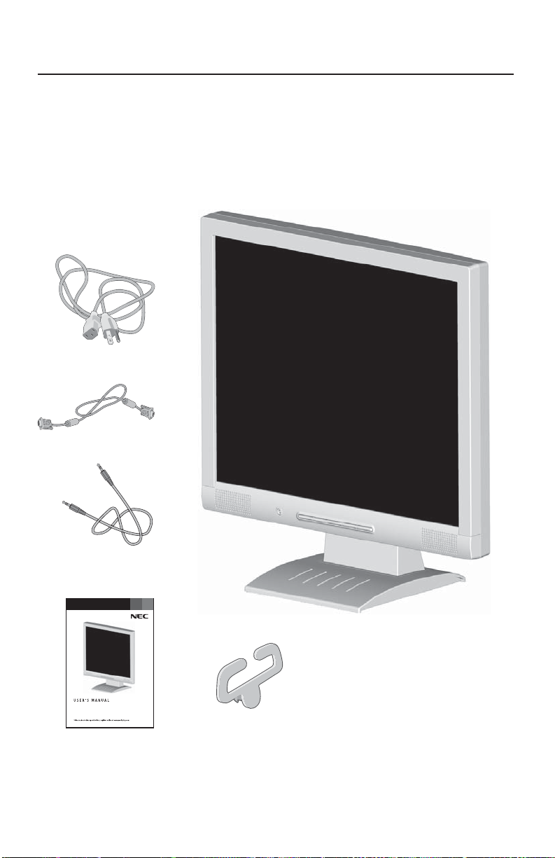
Your new NEC AccuSync LCD monitor box* should contain the following:
• AccuSync LCD Monitor • Video Signal Cable
• Audio Cable • Power Cord
• User’s Manua
• Cable Holder
Video Signal Cable
l • Base Stand
Power Cord
Audio Cable
AccuSync LCD monitor
(stand not connected)
AccuSync™ LCD52VM/72VM/92VM
Cable Holder
User’s Manual
* Remember to save your original box and packing material to transport or ship the monitor.
2
Quick Start
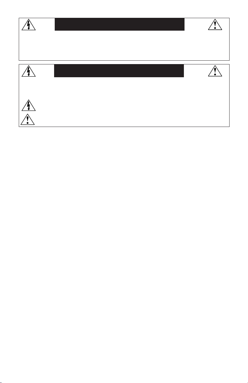
To attach the Base to the LCD Stand:
1. Insert the front of the LCD Stand into the holes in the front of the Base (Figure 1).
2. Next, position the locking tabs on the back side of the LCD Stand with the holes on the
Base. Lower the Stand until locking tabs are secure.
3. Attach the clip into the base (Figure 2).
Figure 1 Figure 2
Stand
Locking Tabs
To attach the AccuSync LCD monitor to your system, follow these instructions:
1. Turn off the power to your computer.
2. For the PC with Analog output: Connect the 15-pin mini D-SUB signal cable to the
connector of the display card in your system (Figure A.1). Tighten all screws.
For the MAC: Connect the AccuSync Macintosh cable adapter to the computer, then
attach the 15-pin mini D-SUB signal cable to the AccuSync Macintosh cable adapter
(Figure A.2). Tighten all screws.
NOTE: To obtain the AccuSync Macintosh cable adapter,
call NEC Display Solutions of America, Inc. at (800) 632-4662.
3. Connect the 15-pin mini D-SUB of the video signal cable to the appropriate connector
on the back of the monitor (Figure B.1). Connect the audio cable to AUDIO-INPUT on
the back of the monitor and the other end to the “Audio out” terminal of the computer.
Headphones may be connected to the “Headphones” output on the front of the
monitor “
be disabled. Headphones can be purchased from your local electronics store.
Connect one end of the power cord to the LCD and the other end to the power outlet. Place
4.
the video signal cable, power cord and audio cable between the cable holder (Figure B.1).
NOTE: Adjust the position of cables between the holder to avoid damage.
NOTE: If you use this monitor at AC125-240V, please refer to Recommended Use
5. Turn on the monitor with the front power button and the computer. (Figure C.1)
6. No-touch Auto Adjust automatically adjusts the monitor to optimal settings upon initial
setup for most timings. For further adjustments, use the following OSM
• Auto Adjust Contrast • Auto Adjust
Refer to the Controls section of this User’s Manual for a full description of these OSM controls.
NOTE: For download information on the Windows® 95/98/Me/2000/XP INF file for your AccuSync
NOTE: If you have any problems, please refer to the Troubleshooting section of this User’s Manual.
”. While the headphones are connected, the sound from the speakers will
section of this manual for proper selection of power cord.
monitor, refer to the References section of this User’s Manual.
Front Base
®
controls:
3

Quick Start –continued
Macintosh Cable
Adapter
(not included)
Power Cable
Figure B.1
Figure A.1
Audio input
Figure A.2
Cable holder
Note: Some Macintosh
systems do not require a
MacintoshCable Adapter
Input (VGA)
Figure C.1
Power button
4
Quick Start –continued
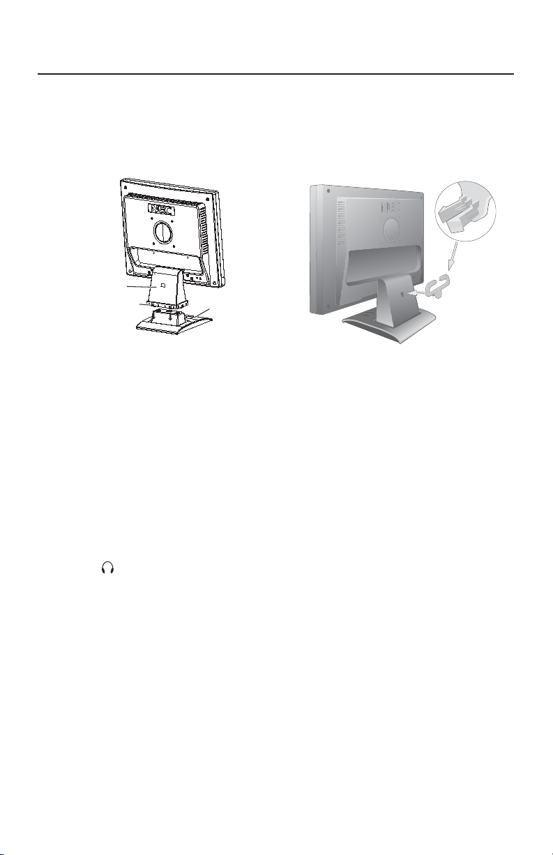
Tilt
Grasp both sides of the monitor screen with your hands
and adjust the tilt as desired (Figure TS.1).
NOTE: Handle with care when tilting the monitor screen.
Remove Monitor Stand for Mounting
To prepare the monitor for alternate mounting purposes:
1.Disconnect all cables.
2.Place monitor face down on a nonabrasive surface (Figure R.1).
3.Remove the 4 screws connecting the monitor to the stand and slide the
stand off from the LCD (Figure R.2).
The monitor is now ready for mounting in an alternate manner.
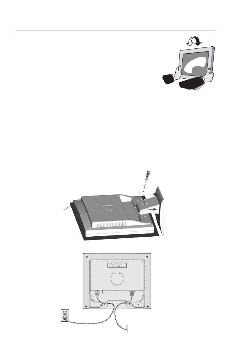
4.
Connect the AC cord and signal cable to the back of the monitor (Figure R.3).
5. Reverse this process to reattach stand.
NOTE: Use only VESA-compatible alternative mounting method.
NOTE: Handle with care when removing monitor stand.
Figure R.1
Figure TS.1
non-abrasive
surface
Figure R.2
5

Quick Start –continued
Removing the Base
Note: Always remove the Base when shipping the LCD.
1.
Place monitor face down on a non-abrasive
surface.
2. While using your thumbs, press the tabs in the
direction of the arrows to unlock the stand.
3. Pull the unlocked base off the stand.
Connecting a Flexible Arm
This LCD monitor is designed for use with a flexible arm. Please use the attached
screws (4pcs) as shown in the picture when installing.
To meet the safety requirements, the monitor must be mounted to an arm which
guaranties the necessary stability under consideration of the weight of the monitor.
The LCD monitor should only be used with an approved arm (e.g. GS mark).
Thickness of
Bracket (Arm)
2.0~3.2 mm
Replace screws
Tighten all
screws.
Specifications
4-SCREWS (M4)
(MAX depth: 8.5 mm)
If using other screws,
check depth of holes.
75 mm (LCD52VM)
100 mm (LCD72VM)
100 mm (LCD92VM)
6
75 mm (LCD52VM)
100 mm (LCD72VM)
100 mm (LCD92VM)
Weight of LCD assembly:
2.9 kg - LCD52VM (MAX)
4.3 kg - LCD72VM (MAX)
5.5 kg - LCD92VM (MAX)
Controls
OSM® (On-Screen Manager) control buttons on the front of the
monitor function as follows:
1. Basic key function
Button
OSM Off
OSM On
(Icon selection
stage)
OSM On
(Adjustment
stage)
OSM displayed
Moves to
Adjustment stage
Moves to Icon
selection stage
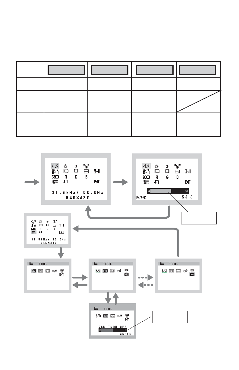
2. OSM Structure
Main Menu (Icon Select)
Press
“SELECT”
key
SELECT
–+AUTO / RESET
Shortcut to bright
adjust window
Cursor moves left
Adjust value
decrease or
Cursor for adjust
moves left
“SELECT”
Press “SELECT” key
Press “SELECT” key
Shortcut to volume
adjust window
Cursor moves right
Adjust value
increase or
Cursor for adjust
moves right
Main Menu (Adjust)
Press
key
VOLUME
MUTE
“Auto adjust“
function
Reset operation
Mute off/on Volume
adjustment window
%
Adjust by using
“–“ or “ +”.
Press “SELECT”
key
Sub Menu (Icon Select)
Press
“–“ or “ +”
Press
“–“ or “ +”
Press “SELECT” key
Adjust by using
“–“ or “ +”.
Sub Menu (Adjust)
7
Controls –continued
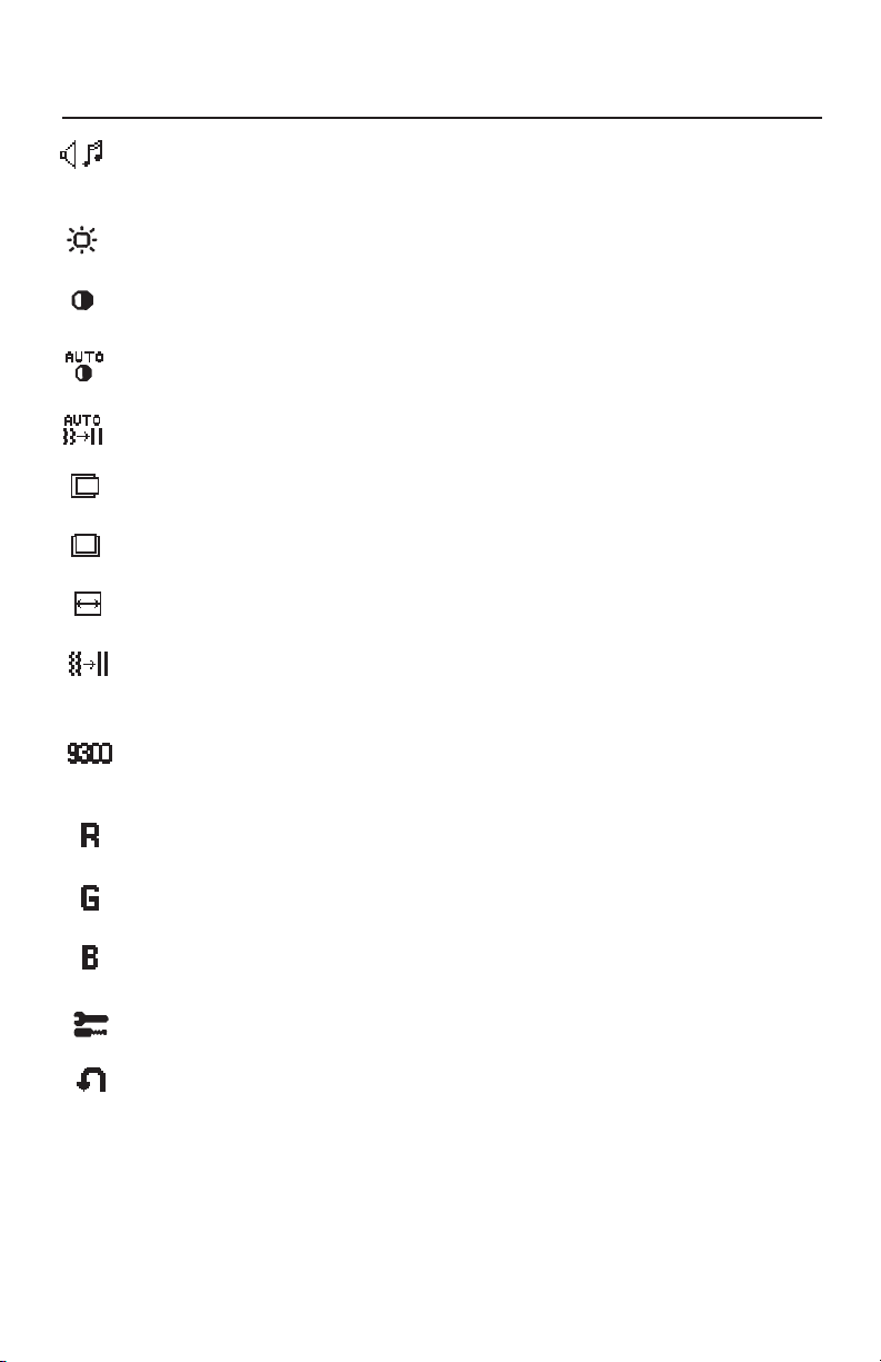
AUDIO
Control the sound volume of speakers and headphone.
To mute the speaker sound, press the AUTO/RESET key.
BRIGHTNESS
Adjusts the overall image and background screen brightness.
CONTRAST
Adjusts the image brightness in relation to the background.
AUTO CONTRAST
Adjusts the image displayed for non-standard video inputs.
AUTO ADJUST
Automatically adjusts the Image Position, the H. Size and Fine setting.
LEFT/RIGHT
Controls Horizontal Image Position within the display area of the LCD.
DOWN/UP
Controls Vertical Image Position within the display area of the LCD.
H. SIZE
Adjusts the horizontal size by increasing or decreasing this setting.
FINE
Improves focus, clarity and image stability by increasing or decreasing
this setting.
COLOR CONTROL SYSTEMS
Four color presets (9300/7500/6500/USER) select the desired color
setting.
COLOR RED
Increase or decreases Red. The change will appear on screen.
COLOR GREEN
Increase or decreases Green. The change will appear on screen.
COLOR BLUE
Increase or decreases Blue. The change will appear on screen.
TOOL
Selecting TOOL allows you to get into the sub menu.
FACTORY PRESET
Selecting Factory Preset allows you to reset all OSM control settings back
to the factory settings. The RESET button will need to be held down for
several seconds to tage effect. Individual settings can be reset by
highlighting the control to be reset and pressing the RESET button.
8
Controls –continued
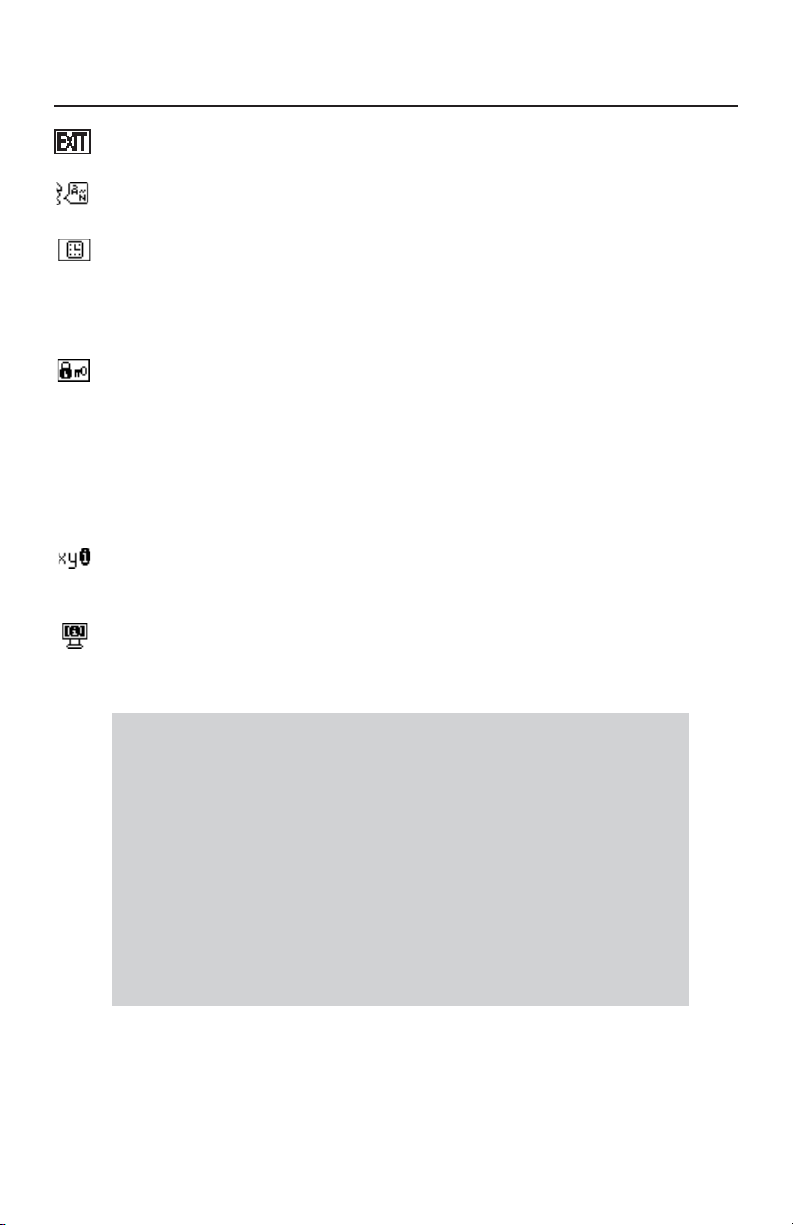
EXIT
Selecting EXIT allows you exit OSM menu/sub menu.
LANGUAGE
OSM control menus are available in seven languages.
OSM TURN OFF
The OSM control menu will stay on as long as it is in use. In the OSM
Turn OFF submenu, you can select how long the monitor waits after
the last touch of a button to shut off the OSM control menu. The preset
choices are 10 - 120 seconds in 5 second intervals.
OSM LOCK OUT
This control completely locks out access to all OSM control functions
without Brightness and Contrast. When attempting to activate OSM
controls while in the Lock Out mode, a screen will appear indicating
the OSM are locked out. To activate the OSM Lock Out function, press
“AUTO/ RESET“, then “+“ key and hold down simultaneously. To deactivate the OSM Lock Out, press “AUTO/ RESET“, then “+“ key and
hold down simultaneously.
RESOLUTION NOTIFIER
If ON is selected, a message will appear on the screen after 30
seconds, notifying you that the resolution is not at optimal resolution.
MONITOR INFO
Indicates the model and serial numbers of your monitor.
OSM® Warning: OSM Warning menus disappear with SELECT button.
NO SIGNAL: This function gives a warning when there is no signal present.
After power is turned on or when there is a change of input signal or video
is inactive, the
RESOLUTION NOTIFIER: This function gives a warning of use with
optimized resolution. After power is turned on or when there is a change
of input signal or the video signal doesn’t have proper resolution, the
Resolution Notifier window will open. This function can be disabled in
the TOOL menu.
OUT OF RANGE: This function gives a recommendation of the optimized
resolution and refresh rate. After the power is turned on or there is a change
of input signal or the video signal doesn’t have proper timing, the
Range
No Signal window will appear.
Out Of
menu will appear.
9
Recommended Use
Safety Precautions and Maintenance
FOR OPTIMUM PERFORMANCE, PLEASE NOTE THE
FOLLOWING WHEN SETTING UP AND USING
THE ACCUSYNC LCD COLOR MONITOR:
• DO NOT OPEN THE MONITOR. There are no user serviceable parts inside and opening or
removing covers may expose you to dangerous shock hazards or other risks. Refer all servicing to
qualified service personnel.
• Do not spill any liquids into the cabinet or use your monitor near water.
• Do not insert objects of any kind into the cabinet slots, as they may touch dangerous voltage
points, which can be harmful or fatal or may cause electric shock, fire or equipment failure.
• Do not place any heavy objects on the power cord. Damage to the cord may cause shock or fire.
• Do not place this product on a sloping or unstable cart, stand or table, as the monitor may fall,
causing serious damage to the monitor.
• When operating the AccuSync LCD monitor with its AC 125-240V power supply, use a power
supply cord that matches the power supply voltage of the AC power outlet being used. The power
supply cord you use must have been approved by and comply with the safety standards of your
country. (Type H05VV-F should be used in Europe)
• In UK, use a BS-approved power cord with molded plug having a black (5A) fuse installed for use
with this monitor. If a power cord is not supplied with this monitor, please contact your supplier.
• Do not place any objects onto the monitor and do not use the monitor outdoors.
• The inside of the fluorescent tube located within the LCD monitor contains mercury.
Please follow the bylaws or rules of your municipality to dispose of the tube properly.
• Do not bend power cord.
• Do not use monitor in high temperature, humid, dusty, or oily areas.
• If glass is broken, handle with care.
• Do not cover vent on monitor.
Immediately unplug your monitor from the wall outlet and refer servicing to qualified service
personnel under the following conditions:
• When the power supply cord or plug is damaged.
• If liquid has been spilled, or objects have fallen into the monitor.
• If the monitor has been exposed to rain or water.
• If the monitor has been dropped or the cabinet damaged.
• If the monitor does not operate normally by following operating instructions.
• If monitor or glass is broken, do not come in contact with the liquid crystal and handle with care.
• Allow adequate ventilation around the monitor so that heat can properly dissipate. Do
not block ventilated openings or place the monitor near a radiator or other heat
sources. Do not put anything on top of monitor.
• The power cable connector is the primary means of detaching the system from the
CAUTION
Image Persistence
Image persistence is when a residual or “ghost” image of a previous image remains visible on the
screen. Unlike CRT monitors, LCD monitors’ image persistence is not permanent, but constant images
being displayed for a long period of time should be avoided.
To alleviate image persistence, turn off the monitor for as long as the previous image was displayed.
For example, if an image was on the monitor for one hour and a residual image remains, the monitor
should be turned off for one hour to erase the image.
NOTE: As with all personal display devices, NEC DISPLAY SOLUTIONS recommends using a moving
screen saver at regular intervals whenever the screen is idle or turning off the monitor when not in
use.
power supply. The monitor should be installed close to a power outlet which is easily accessible.
• Handle with care when transporting. Save packaging for transporting.
10
Recommended Use –continued
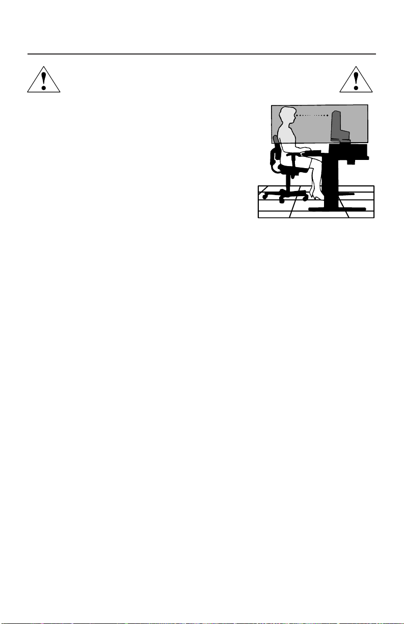
CORRECT PLACEMENT AND ADJUSTMENT OF THE MONITOR
CAN REDUCE EYE, SHOULDER AND NECK FATIGUE. CHECK THE
FOLLOWING WHEN YOU POSITION THE MONITOR:
• For optimum performance, allow 20 minutes for
warm-up.
• Adjust the monitor height so that the top of the
screen is at or slightly below eye level. Your eyes
should look slightly downward when viewing the
middle of the screen.
•
Position your monitor no closer than 16 inches
and no further away than 28 inches from your
eyes. The optimal distance is 20 inches.
• Rest your eyes periodically by focusing on an
object at least 20 feet away. Blink often.
• Position the monitor at a 90° angle to windows and other light sources to
minimize glare and reflections. Adjust the monitor tilt so that ceiling lights do
not reflect on your screen.
• If reflected light makes it hard for you to see your screen, use an antiglare filter.
• Clean the LCD monitor surface with a lint-free, nonabrasive cloth. Avoid using
any cleaning solution or glass cleaner!
• Adjust the monitor’s brightness and contrast controls to enhance readability.
• Use a document holder placed close to the screen.
• Position whatever you are looking at most of the time (the screen or
reference material) directly in front of you to minimize turning your head
while you are typing.
• Avoid displaying fixed patterns on the monitor for long periods of time to avoid
image persistence (afterimage effects).
• Get regular eye checkups.
Ergonomics
To realize the maximum ergonomics benefits, we recommend the following:
•
Use the preset Size and Position controls with standard signals
•
Use the preset Color Setting
•
Use non-interlaced signals with a vertical refresh rate between 60-75Hz
•
Do not use primary color blue on a dark background, as it is difficult to see and
may produce eye fatigue to insufficient contrast
For more detailed information on setting up a healthy work environment, write the
American National Standard for Human Factors Engineering of Visual Display Terminal
Workstations – ANSI-HFS Standard No. 100-1988 – The Human Factors Society, Inc.
P.O. Box 1369, Santa Monica, California 90406.
11
Specifications
Monitor AccuSync LCD52VM Notes
Specifications Monitor
LCD Module Diagonal: 15.0 inch Active matrix; thin film transistor (TFT)
Input Signal Video: ANALOG 0.7 Vp-p/75 Ohms
Display Colors Analog input: 16,194,277 Depending on display card used.
Maximum Left/Right: 60°/60° (CR>10)
Viewing Angles Up/Down: 45°/45° (CR>10)
Synchronization Horizontal: 31.5 kHz to 61 kHz Automatically
Range Vertical: 55 Hz to 76 Hz Automatically
Resolutions Supported 720 x 400*
Active Display Area Horizontal :
Power Supply
Speaker Practical Audio Output
Current Rating 0.5 - 0.3A/100-240V
Dimensions
Weight 3.3 kg
Environmental Considerations
Viewable Image Size: 15.0 inch liquid crystal display (LCD); 0.297 mm dot
Native Resolution (Pixel Count): 1024 x 768 pitch; 250cd/m
Sync: Separate sync TTL Level (Positive/Negative)
Horizontal sync Positive/Negative
Vertical sync Positive/Negative
1
-240 V
:VGA text
1
at 75 Hz
~ 50/60 Hz
640 x 480*1 at 60 Hz to 75 Hz
800 x 600*1 at 56 Hz to 75 Hz
832 x 624*
1024 x 768 at 60 Hz to 75 Hz ..................
Vertical :
Operating Temperature: 5°C to 35°C/41°F to 95°F
Humidity: 30% to 80%
Storage Temperature: -10°C to 60°C/14°F to 140°F
Humidity: 10% to 85%
304.1 mm/12.0 inches
228.1 mm/9.0 inches
100
1 + 1 Watts
344.6 mm (W) x 352.7 mm (H) x 165 mm (D)
13.6 inches (W) x 13.9 inches (H) x 6.5 inches (D)
7.3 lbs
Feet: 0 to 10,000 Feet
Feet: 0 to 40,000 Feet
400:1 contrast ratio, typical
Some systems may not support
all modes listed.
NEC DISPLAY SOLUTIONS cites
recommended resolution at 60 Hz for
optimal display performance.
2
white luminence;
*1 Interpolated Resolutions: When resolutions are shown that are lower than the pixel count of the LCD module, text may appear different. This is
normal and necessary for all current flat panel technologies when displaying nonnative resolutions full screen. In flat panel technologies, each
dot on the screen is actually one pixel, so to expand resolutions to full screen, an interpolation of the resolution must be done.
NOTE: Technical specifications are subject to change without notice.
12

Specifications –continued
Monitor AccuSync LCD72VM Notes
Specifications Monitor
LCD Module Diagonal: 17.0 inch Active matrix; thin film transistor (TFT)
Input Signal Video: ANALOG 0.7 Vp-p/75 Ohms
Display Colors Analog input: 16,194,277 Depending on display card used.
Maximum Left/Right: 70°/70° (CR>10)
Viewing Angles Up/Down: 65°/60° (CR>10)
Synchronization Horizontal: 31.5 kHz to 81.1 kHz Automatically
Range Vertical: 55 Hz to 76 Hz Automatically
Resolutions Supported 720 x 400*
Active Display Area Horizontal :
Power Supply
Speaker Practical Audio Output
Current Rating 0.6 - 0.4A/100-240V
Dimensions
Weight 4.7 kg
Environmental Considerations
Viewable Image Size: 17.0 inch liquid crystal display (LCD); 0.264 mm dot
Native Resolution (Pixel Count): 1280 x 1024 pitch; 250cd/m
Sync: Separate sync TTL Level (Positive/Negative)
Horizontal sync Positive/Negative
Vertical sync Positive/Negative
1
640 x 480*1 at 60 Hz to 75 Hz
800 x 600*1 at 56 Hz to 75 Hz
832 x 624*
1024 x 768*
1152 x 864*
1152 x 870*
1280 x 960
1280 x 1024 at 60 Hz to 75 Hz................
Vertical :
Operating Temperature: 5°C to 35°C/41°F to 95°F
Humidity: 30% to 80%
Storage Temperature: -10°C to +60°C/14°F to 140°F
Humidity: 10% to 85%
338 mm/13.3 inches
270.3 mm/10.6 inches
100
1 + 1 Watts
375.4 mm (W) x 389 mm (H) x 180 mm (D)
14.8 inches (W) x 15.3 inches (H) x 7.1 inches (D)
10.4 lbs
Feet: 0 to 10,000 Feet
Feet: 0 to 40,000 Feet
: VGA text
1
at 75 Hz
1
at 60 Hz to 75 Hz
1
at 70 Hz
1
at 75 Hz
*1 at 60 Hz to 75 Hz
-240 V
~ 50/60 Hz
450:1 contrast ratio, typical
Some systems may not support
all modes listed.
NEC DISPLAY SOLUTIONS cites
recommended resolution at 60 Hz for
optimal display performance.
2
white luminence;
*1 Interpolated Resolutions: When resolutions are shown that are lower than the pixel count of the LCD module, text may appear different. This is
normal and necessary for all current flat panel technologies when displaying non-native resolutions full screen. In flat panel technologies, each
dot on the screen is actually one pixel, so to expand resolutions to full screen, an interpolation of the resolution must be done.
NOTE: Technical specifications are subject to change without notice.
13

Specifications –continued
Monitor AccuSync LCD92VM Notes
Specifications Monitor
LCD Module Diagonal: 19.0 inch Active matrix; thin film transistor (TFT)
Input Signal Video: ANALOG 0.7 Vp-p/75 Ohms
Display Colors Analog input: 16,194,277 Depending on display card used.
Maximum Left/right: 65°/65° (CR>10)
Viewing Angles Up/Down: 65°/65° (CR>10)
Synchronization Horizontal: 31.5 kHz to 81.1 kHz Automatically
Range Vertical: 55 Hz to 76 Hz Automatically
Resolutions Supported 720 x 400*
Active Display Area Horizontal :
Power Supply
Speaker Practical Audio Output
Current Rating 0.8 - 0.5A/100-240V
Dimensions
Weight 6.5 kg
Environmental Considerations
Viewable Image Size: 19.0 inch liquid crystal display (LCD); 0.294 mm dot
Native Resolution (Pixel Count): 1280 x 1024 pitch; 250cd/m
Sync: Separate sync TTL Level (Positive/Negative)
Horizontal sync Positive/Negative
Vertical sync Positive/Negative
1
-240 V
*1 at 75 Hz
~ 50/60 Hz
: VGA text
1
at 75 Hz
1
at 60 Hz to 75 Hz
1
at 70 Hz
1
at 75 Hz
640 x 480*1 at 60 Hz to 75 Hz
800 x 600*1 at 56 Hz to 75 Hz
832 x 624*
1024 x 768*
1152 x 864*
1152 x 870*
1280 x 960
1280 x 1024 at 60 Hz to 75 Hz................
Vertical :
Operating Temperature: 5°C to 35°C/41°F to 95°F
Humidity: 30% to 80%
Storage Temperature: -10°C to +60°C/14°F to 140°F
Humidity: 10% to 85%
376 mm/14.8 inches
301 mm/11.9 inches
100
1 + 1 Watts
418 mm (W) x 427.8 mm (H) x 199.5 mm (D)
16.5 inches (W) x 14.6 inches (H) x 7.9 inches (D)
14.3 lbs
Feet: 0 to 10,000 Feet
Feet: 0 to 40,000 Feet
450:1 contrast ratio, typical
Some systems may not support
all modes listed.
NEC DISPLAY SOLUTONS cites
recommended resolution at 60 Hz for
optimal display performance.
2
white luminence;
*1 Interpolated Resolutions: When resolutions are shown that are lower than the pixel count of the LCD module, text may appear different. This is
normal and necessary for all current flat panel technologies when displaying non-native resolutions full screen. In flat panel technologies, each
dot on the screen is actually one pixel, so to expand resolutions to full screen, an interpolation of the resolution must be done.
NOTE: Technical specifications are subject to change without notice.
14

Features
Reduced Footprint: Provides the ideal solution for environments requiring superior image
quality but with size and weight limitations. The monitor’s small footprint and low weight
allow it to be moved or transported easily from one location to another.
AccuColor® Control Systems: Allows you to adjust the colors on your screen and customize
the color accuracy of your monitor to a variety of standards.
OSM® (On-Screen Manager) Controls: Allow you to quickly and easily adjust all elements
of your screen image via simple to use on-screen menus.
No-touch Auto Adjust™: No-touch Auto Adjust automatically adjusts the monitor to
optimal settings upon initial setup.
®
ErgoDesign
protect the health of the user and save money. Examples include
and easy image adjustments, tilt base for preferred angle of vision, small footprint and
compliance with MPRII and TCO guidelines for lower emissions
Plug and Play: The Microsoft
ing system facilitates setup and installation by allowing
(such as screen size and resolutions supported)
optimizing display performance.
IPM® (Intelligent Power Manager) System: Provides innovative power-saving methods that
allow the monitor to shift to a lower power consumption level when on but not in use,
saving two-thirds of your monitor energy costs, reducing emissions and lowering the air
conditioning costs of the workplace.
Multiple Frequency Technology: Automatically adjusts monitor to the display card’s
scanning frequency, thus displaying the resolution required.
FullScan
significantly expanding image size.
VESA® Standard Mounting Interface: Allows users to connect their AccuSync monitor to
any VESA standard third party mounting arm or bracket. Allows for the monitor to be
mounted on a wall or an arm using any third party compliant device.
Features: Enhance human ergonomics to improve the working environment,
OSM controls for quick
.
®
solution with the Windows®95/98/Me/2000/XP operat-
the monitor to send its capabilities
directly to your computer, automatically
®
Capability: Allows you to use the entire screen area in most resolutions,
OSM Display Screen Copyright 2004 by
NEC Display Solutions of America, Inc.
15

Troubleshooting
No picture
•
The signal cable should be completely connected to the display card/computer.
• The display card should be completely seated in its slot.
• Front Power Switch and computer power switch should be in the ON position.
•
Check to make sure that a supported mode has been selected on the display card or system
being used. (Please consult display card or system manual to change graphics mode.)
• Check the monitor and your display card with respect to compatibility and recommended settings.
• Check the signal cable connector for bent or pushed-in pins.
Power Button does not respond
• Unplug the power cord of the monitor from the AC outlet to turn off and reset the monitor.
Image Persistence
•
Image persistence is when a residual or “ghost” image of a previous image remains visible
on the screen. Unlike CRT monitors, LCD monitors’ image persistence is not permanent, but
constant images being displayed for a long period of time should be avoided.
To alleviate image persistence, turn off the monitor for as long as the previous image was
displayed. For example, if an image was on the monitor for one hour and a residual
image remains, the monitor should be turned off for one hour to erase the image.
NOTE: As with all personal display devices, NEC DISPLAY SOLUTIONS recommends
using a moving screen saver at regular intervals whenever the screen is idle or turning
off the monitor when not in use.
Image is unstable, unfocused or swimming is apparent
• Signal cable should be completely attached to the computer.
• Use the OSM Image Adjust controls to focus and adjust display by increasing or
decreasing the FINE control. When the display mode is changed, the OSM Image
Adjust settings may need to be readjusted.
• Check the monitor and your display card with respect to compatibility
and recommended signal timings.
•
If your text is garbled, change the video mode to non-interlace and use 60Hz refresh rate.
LED on monitor is not lit
• Power Switch should be in the ON position and power cord should be connected.
Display image is not sized properly
• Use the OSM Image Adjust controls to increase or decrease the H.SIZE.
•
Check to make sure that a supported mode has been selected on the display card or system
being used. (Please consult display card or system manual to change graphics mode.)
No Video
• If no video is present on the screen, turn the Power button off and on again.
• Make certain the computer is not in a power-saving mode (touch the keyboard or mouse).
No Sound
• Check to see if speaker cable is properly connected.
• Check to see if mute is activated.
• Check to see if volume in OSM is set at minimum.
(no green or amber color can be seen)
16

References
NEC Monitor Customer Service & Support
Customer Service and Technical Support:
Parts and Accessories/Macintosh
Cable Adapter: (800) 632-4662
Warranty Information: www.necdisplay.com
Online Technical Support www.necdisplay.com
Sales and Product Information
Sales Information Line: (888) 632-6487
Canadian Customers: (866) 771-0266, Ext#: 4037
Government Sales: (800) 284-6320
Government Sales email: gov@necdisplay.com
Electronic Channels
World Wide Web: www.necdisplay.com
Product Registration: www.necdisplay.com
European Operations: www.nec-display-solutions.com
(800) 632-4662
Fax: (800) 695-3044
Drivers and Downloads www.necdisplay.com
17

Limited Warranty
NEC Display Solutions of America, Inc. (hereinafter “NEC DISPLAY SOLUTIONS”) warrants
this Product to be free from defects in material and workmanship and, subject to the conditions
set forth below, agrees to repair or replace (at NEC DISPLAY SOLUTIONS’ sole option) any
part of the enclosed unit which proves defective for a period of three (3) years from the date
of first consumer purchase. Spare parts are warranted for ninety (90) days. Replacement parts
or unit may be new or refurbished and will meet specifications of the original parts or unit.
This warranty gives you specific legal rights and you may also have other rights, which vary
from state to state. This warranty is limited to the original purchaser of the Product and is not
transferable. This warranty covers only NEC DISPLAY SOLUTIONS-supplied components.
Service required as a result of third party components is not covered under this warranty. In
order to be covered under this warranty, the Product must have been purchased in the U.S.A.
or Canada by the original purchaser. This warranty only covers Product distribution in the
U.S.A. or Canada by NEC DISPLAY SOLUTIONS No warranty service is provided outside of
the U.S.A. or Canada. Proof of Purchase will be required by NEC DISPLAY SOLUTIONS to
substantiate date of purchase. Such proof of purchase must be an original bill of sale or receipt
containing name and address of seller, purchaser, and the serial number of the product.
It shall be your obligation and expense to have the Product shipped, freight prepaid, or
delivered to the authorized reseller from whom it was purchased or other facility authorized
by NEC DISPLAY SOLUTIONS to render the services provided hereunder in either the original
package or a similar package affording an equal degree of protection. All Products returned
to NEC DISPLAY SOLUTIONS for service MUST have prior approval, which may be obtained
by calling 1-800-632-4662. The Product shall not have been previously altered, repaired, or
serviced by anyone other than a service facility authorized by NEC DISPLAY SOLUTIONS to
render such service, the serial number of the product shall not have been altered or removed.
In order to be covered by this warranty the Product shall not have been subjected to displaying
of fixed images for long periods of time resulting in image persistence (afterimage effects),
accident, misuse or abuse or operation contrary to the instructions contained in the User’s
Manual. Any such conditions will void this warranty.
NEC DISPLAY SOLUTIONS SHALL NOT BE LIABLE FOR DIRECT, INDIRECT, INCIDENTAL,
CONSEQUENTIAL, OR OTHER TYPES OF DAMAGES RESULTING FROM THE USE OF ANY
NEC DISPLAY SOLUTIONS PRODUCT OTHER THAN THE LIABILITY STATED ABOVE. THESE
WARRANTIES ARE IN LIEU OF ALL OTHER WARRANTIES EXPRESSED OR IMPLIED,
INCLUDING, BUT NOT LIMITED TO, THE IMPLIED WARRANTIES OF MERCHANTABILITY OR
FITNESS FOR A PARTICULAR PURPOSE. SOME STATES DO NOT ALLOW THE EXCLUSION
OF IMPLIED WARRANTIES OR THE LIMITATION OR EXCLUSION OF LIABILITY FOR
INCIDENTAL OR CONSEQUENTIAL DAMAGES SO THE ABOVE EXCLUSIONS OR LIMITATIONS MAY NOT APPLY TO YOU.
This Product is warranted in accordance with the terms of this limited warranty. Consumers
are cautioned that Product performance is affected by system configuration, software, the
application, customer data, and operator control of the system, among other factors. While
NEC DISPLAY SOLUTIONS Products are considered to be compatible with many systems,
specific functional implementation by the customers of the Product may vary. Therefore,
suitability of a Product for a specific purpose or application must be determined by consumer
and is not warranted by NEC DISPLAY SOLUTIONS.
For the name of your nearest authorized NEC DISPLAY SOLUTIONS service facility, contact
NEC Display Solutions of America, Inc. at 1-800-632-4662.
18

TCO’99
Congratulations! You have just purchased a TCO’99 approved and
labelled product! Your choice has provided you with a product developed
for professional use. Your purchase has also contributed to reducing the
burden on the environment and also to the further development of
environmentally adapted electronics products.
Why do we have environmentally labelled computers?
In many countries, environmental labelling has become an established method for encouraging the adaptation of goods and services to the environment. The main problem, as far as
computers and other electronics equipment are concerned, is that environmentally harmful
substances are used both in the products and during the manufacturing. Since it has not been
possible for the majority of electronics equipment to be recycled in a satisfactory way, most
of these potentially damaging substances sooner or later enter Nature.
There are also other characteristics of a computer, such as energy consumption levels, that are
important from the viewpoints of both the work (Internal) and natural (external) environments.
Since all methods of conventional electricity generation have a negative effect on the
environment (acidic and climate-influencing emissions, radioactive waste, etc.), it is vital to
conserve energy. Electronics equipment in offices consume an enormous amount of energy
since they are often left running continuously.
What does labelling involve?
This product meets the requirements for the TCO’99 scheme which provides for international and
environmental labelling of personal computers. The labelling scheme was developed as a joint
effort by the TCO (The Swedish Confederation of Professional Employees), Svenska
Naturskyddsforeningen (The Swedish Society for Nature Conservation) and Statens Energimyndighet
(The Swedish National Energy Administration).
The requirements cover a wide range of issues: environment, ergonomics, usability, emission of
electrical and magnetic fields, energy consumption and electrical and fire safety.
The environmental demands concern restrictions on the presence and use of heavy metals,
brominated and chlorinated flame retardants, CFCs (freons) and chlorinated solvents, among other
things. The product must be prepared for recycling and the manufacturer is obliged to have an
environmental plan which must be adhered to in each country where the company implements its
operational policy. The energy requirements include a demand that the computer and/or display,
after a certain period of inactivity, shall reduce its power consumption to a lower level in one or
more stages. The length of time to reactivate the computer shall be reasonable for the user.
Labelled products must meet strict environmental demands, for example, in respect of the reduction
of electric and magnetic fields, physical and visual ergonomics and good usability.
Environmental Requirements
Flame retardants
Flame retardants are present in printed circuit boards, cables, wires, casings and housings. In turn,
they delay the spread of fire. Up to thirty percent of the plastic in a computer casing can consist of
flame retardant substances. Most flame retardants contain bromine or chloride and these are
related to another group of environmental toxins, PCBs, which are suspected to give rise to severe
health effects, including reproductive damage in fisheating birds and mammals, due to the bio-
19

TCO’99 –continued
accumulative* processes. Flame retardants have been found in human blood and researchers fear
that disturbances in foetus development may occur.
TCO’99 demand requires that plastic components weighing more than 25 grams must not contain
flame retardants with organically bound chlorine and bromine. Flame retardants are allowed in
the printed circuit boards since no substitutes are available.
Lead**
Lead can be found in picture tubes, display screens, solders and capacitors. Lead damages the
nervous system and in higher doses, causes lead poisoning.
TCO’99 requirement permits the inclusion of lead since no replacement has yet been developed.
Cadmium**
Cadmium is present in rechargeable batteries and in the color generating layers of certain computer
displays. Cadmium damages the nervous system and is toxic in high doses.
TCO’99 requirement states that batteries, the color generating layers of display screens and the
electrical or electronics components must not contain any cadmium.
Mercury**
Mercury is sometimes found in batteries, relays and switches, Mercury damages the nervous system
and is toxic in high doses.
TCO’99 requirement states that batteries may not contain any Mercury. It also demands that no
mercury is present in any of the electrical or electronics components associated with the display unit.
CFCs (freons)
CFCs (freons) are sometimes used for washing printed circuit boards. CFCs break down ozone and
thereby damage the ozone layer in the stratosphere, causing increased reception on Earth of
ultraviolet light with consequent increased risks of skin cancer (malignant melanoma).
The relevant TCO’99 requirement; Neither CFCs nor HCFCs may be used during the manufacturing
and assembly of the product or its packaging.
*Bio-accumulative is defined as substances which accumulate within living organisms.
**Lead, Cadmium and Mercury are heavy metals which are Bio-accumulative.
To obtain complete information on the environmental criteria document, order from:
TCO Development Unit
SE-114 94 Stockholm
SWEDEN
FAX Number: +46 8 782 92 07
E-mail (Internet): development@tco.se
You may also obtain current information on TCO’99 approved and labelled products by
visiting their website at: http://www.tcodevelopment.com/
20

Declaration of the Manufacturer
We hereby certify that the color monitor
AccuSync LCD52VM (L154F0),
AccuSync LCD72VM (L174F1), or
AccuSync LCD92VM (L194F2)
are
in compliance with
Council Directive 73/23/EEC:
– EN 60950-1
Council Directive 89/336/EEC:
– EN 55022
– EN 61000-3-2
– EN 61000-3-3
– EN 55024
and marked with
NEC Display Solutions, Ltd.
4-13-23, Shibaura,
Minato-Ku
Tokyo 108-0023, Japan
21
AVERTISSEMENT
AFIN D’ÉVITER TOUT RISQUE D’INCENDIE OU D’ÉLECTROCUTION, NE PAS EXPOSER CET APPAREIL À LA PLUIE OU À
L’HUMIDITÉ. NE PAS UTILISER LA FICHE D’ALIMENTATION POLARISÉE AVEC UNE PRISE DE CORDON DE RALLONGE
OU AUTRE PRISE SAUF SI LES BROCHES PEUVENT ÊTRE ENTIÈREMENT INTRODUITES.
NE PAS OUVRIR LE BOÎTIER, LEQUEL CONTIENT DES COMPOSANTS À HAUTE TENSION. CONFIER TOUS TRAVAUX
À DU PERSONNEL TECHNIQUE QUALIFIÉ.
ATTENTION
ATTENTION : POUR ÉVITER TOUT RISQUE D'ÉLECTROCUTION, NE PAS OUVRIR LE COUVERCLE (L'ARRIÈRE). À L'INTÉRIEUR, AUCUNE
PIÈCE NE NÉCESSITE L'INTERVENTION DE L'UTILISATEUR. EN CAS DE PROBLÈME, S'ADRESSER À DU PERSONNEL TECHNIQUE QUALIFIÉ.
Ce symbole est une mise en garde contre les risques d'électrocution que présentent certaines parties dépourvues
d'isolation à l'intérieur de l'appareil. Il est donc dangereux d'établir le moindre contact avec ces parties
Ce symbole prévient l'utilisateur que des directives d'utilisation et de maintenance de cet appareil sont fournies avec
ce guide d’utilisateur. Par conséquent, celles-ci doivent être lues attentivement pour éviter tout incident.
.
Déclaration de conformité – Département des Communications du Canada
DOC : Cet appareil numérique de classe B respecte toutes les exigences du Règlement
sur le matériel à l'origine d'interférences du Canada.
C-UL : Ce produit porte la marque «C-UL» et est conforme aux règlements de sécurité
canadiens selon CAN/CSA C22.2 No. 60950-1.
Informations FCC
1. Utiliser les câbles spécifiés fournis avec les moniteur couleur AccuSync LCD52VM (L154F0), AccuSync
LCD72VM (L174F1), au AccuSync LCD92VM (L194F2) afin de ne pas provoquer d'interférences avec
la réception radio et télévision.
(1) Prière d'utiliser le câble d'alimentation fourni ou équivalent pour assurer la conformité FCC.
(2) Veuillez utiliser le câble de signal vidéo blindé fourni.
L'utilisation d'autres câbles et adaptateurs peut provoquer des interférences avec la réception
radio et télévision.
2.
Cet appareil a été testé et s’avère conforme avec les spécifications d'équipements de Classe B, section 15
de la réglementation FCC. Ces spécifications ont été établies pour garantir une protection raisonnable
contre les interférences nuisibles dans une installation résidentielle. Cet appareil génère, utilise et peut
émettre des fréquences radio et, s'il n'est pas installé et utilisé selon les directives de ce guide, il peut
perturber les communications radio. Cependant, il n'est pas garanti qu'aucune interférence ne se produira
dans une installation donnée.
Si cet appareil provoque des interférences nuisibles à la réception radio ou télévision, ce que vous pouvez
déterminer en allumant et en éteignant l'appareil, essayez de remédier au problème en prenant une ou
plusieurs des mesures suivantes :
• Réorienter ou repositionner l'antenne de réception.
• Augmenter la distance entre l'appareil et le récepteur.
• Connecter l'appareil à une prise de courant sur un circuit différent de celui sur lequel le récepteur
est connecté.
• Consulter son revendeur ou un technicien radio/TV pour obtenir de l'aide.
Si nécessaire, l'utilisateur doit contacter le revendeur ou un technicien radio/TV afin d'obtenir des
informations supplémentaires. L'utilisateur peut se procurer le livret utile suivant, préparé par la Federal
Communications Commission : «How to Identify and Resolve Radio-TV Interference Problems» (Comment
cerner et résoudre les problèmes d’interférences radio/TV). Ce livret est disponible auprès du U.S.
Government Printing Office, Washington, D.C., 20402, Stock No. 004-000-00345-4.
22
Contenu
La boîte* de votre nouveau moniteur NEC AccuSync LCD contient :
• Moniteur AccuSync LCD • Câble pour le signal vidéo
• Câble d’audio • Cordon d'alimentation
• Manuel de l’utilisateur • Socle de base
• Trous à l’avant de la base
Cordon d'alimentation
Câble pour le signal vidéo
Câble d’audio
Moniteur AccuSync LCD
(Socle non connect)
AccuSync™ LCD52VM/72VM/92VM
Manuel de l’utilisateur
* Ne pas oublier de conserver la boîte et le matériel d'emballage d'origine pour transporter ou expédier le moniteur.
Trous à l’avant de la base
23

Mise en marche rapide
Pour attacher la base au support LCD :
1. Insérez la partie avant du support LCD dans les trous à l’avant de la base (Figure 1).
2. Ensuite, alignez les languettes de verrouillage à l’arrière du stand LCD avec les trous de la base.
Abaissez le support en place jusqu’à ce que les languettes de verrouillage soient maintenues en place.
3. Fixez l’agrafe dans la base (Figure 2).
Figure 1
Support
Languettes de verrouillage
Trous à l’avant
de la base
Figure 2
Pour raccorder le moniteur AccuSync LCD au système,suivez les directives
ciaprès:
1. Mettez l’ordinateur hors tension.
2. PC : Branchez le mini-connecteur D-SUB à 15 broches du câble vidéo approprié dans le
connecteur de la carte vidéo de votre ordinateur (Figure A.1). Serrez toutes les vis.
Macintosh : Branchez l’adaptateur de câble Macintosh pour AccuSync dans l’ordinateur.
Branchez le du câble vidéo dans l’adaptateur de câble Macintosh pour AccuSync (Figure A.2).
Serrez toutes les vis.
NOTA : Pour obtenir un adaptateur de câble Macintosh pour le AccuSync appelez
NEC Display Solutions of America, Inc. au (800) 632-4662.
3. Connecter le mini D-SUB à 15 broches du câble de signal vidéo au connecteur approprié à
l’arrière du moniteur (Figure B.1). Branchez le câble d’audio aux AUDIO-INPUT à avant du
moniteur et l’autre extrémité à la prise de sortie audio fichesur l’ordinateur.
Connectez une écouteur à “écouteur” fiche à devant le moniteur “
casque d’écoute est insérée dans la prise du casque d’écoute, les haut-parleurs sont débranchés
automatiquement et le son se fait entendre à travers les écouteurs. Vous pouvez vous procurer
une écouteur chez votre magasin d’électroni-que local.
4. Connectez une extrémité du câble d’alimentation sur l’adaptateur AC et l’autre extrémité sur la
prise de secteur. Placer le câble de signal vidéo, cordon d’alimentation et câble d’audio entre le
couvercle du câble (Figure B.1).
NOTA : Régler la position des câbles sous la fixation pour éviter d’endommager l’appareil.
NOTA : Si vous utilisez ce moniteur à AC125-240V, s'il vous plaît faites référence à section de
l'Usage Recommandée de ce manuel pour sélection adéquate d'AC pouvoir cordon.
5. Allume l’écran de Silhouette de bouton et l’ordinateur. (Figure C.1)
6.
Auto aucune de tact ajuste automatiquement ajuste l’écran à réglages optimaux sur setup initial pour
les les plus nombreux minutages. Pour les réajustements plus further, following OSM utilise des réglages:
• Contraste automatique • Réglage automatique
Pour une description complète de ces commandes OSM, consultez la section Commandes de ce manuel.
NOTA: des informations sur le télé chargement du fichier INF Windows® 95/98/Me/2000/XP pour
le moniteur AccuSync, consultez la section Références de ce manuel.
NOTA: case de problème,consultez la section Dépannage de ce manuel.
”. Lorsque la fiche du
24

Mise en marche rapide (suite)
Figure A.1
Câble d’audio
Cordon d'alimentation
Figure B.1
Figure A.2
Adaptateur
Macintosh
(non fourni)
Remarque:
Certains systémes
Macintosh ne
nécessitent pas un
adaptateur de
câble Macintosh.
Input (VGA)
Étrier de câble
Figure C.1
Bouton
d’alimentaion
25

Mise en marche rapide (suite)
Incliner
Attrapez des deux mains l’écran du moniteur par
les deux côtés et réglez l’inclinaison et l’orientation
selon votre goût (Figure TS.1).
NOTA: manipulez avec soin en inclinant l’écran de moniteur.
Enlever le support du moniteur pour le montage
Pour préparer le moniteur à différents types de montage :
1. Déconnectez tous les câbles.
2.
Placez le moniteur avec l’écran vers le bas sur une surface non abrasive (Figure R.1).
2. Enlever les 4 vis qui fixent le moniteur au support et enlever la plaque métallique
(Figure R.1).
Vous pouvëz à présent modifier le montage du moniteur.
4. Connectez les AC attachent avec une corde et câble du signal au dos du moniteur
(Figure R.2).
5. Inversez la marche à suivre pour réinstaller le support.
NOTA : Utilisez uniquerment une méthode de montage compatible VESA.
NOTA : Prenez des précautions pour ôter le support du moniteur.
Figure R.1
Figure TS.1
Surface non
abrasive
Figure R.2
26

Mise en marche rapide (suite)
Enlever la Base
NOTA : Toujours enlever la base avant d’expédier le LCD.
1.
Placer le moniteur partie avant en contact avec
une surface non abrasive (Figure R.1).
2. À l’aide des pouces, appuyer sur les
languettes inférieures en les poussant vers le
bas pour déverrouiller.
3. Appuyer sur les languettes supérieures en les
poussant vers le haut pour déverrouiller et tirer le support.
Connexion d’un bras souple
Ce moniteur LCD a été conçu pour être utilisé avec un bras flexible. Utiliser les vis
fournies (4pièces) lors de l’installation comme indiqué sur la figure.
Le moniteur doit être installé sur un bras garantissant la stabilité nécessaire
correspondant au poids du moniteur.
Ce moniteur LCD ne peut être unilisé qu’ avec un bras homoloqué (par ex. marque GS).
L‘épaisseur de
parenthése
Reemplacez des vis
(Arme)
2,0~3,2 mm
Tighten all
screws.
Fiche Technique
4 vis (M4)
(MAX depth: 8,5 mm)
Si utilisant d‘autres vis,
profondeur de che`que
de trou.
75 mm (LCD52VM)
100 mm (LCD72VM)
100 mm (LCD92VM)
27
75 mm (LCD52VM)
100 mm (LCD72VM)
100 mm (LCD92VM)
Poids of assemblee:
2,9 kg - LCD52VM (MAX)
4,3 kg - LCD72VM (MAX)
5,5 kg - LCD92VM (MAX)

Commandes
Les boutons de réglage OSM situés sur l’avant du moniteur fournissent les
fonctions suivantes :
1. Fonction de la touche de base
Button
Arrêt OSM
OSM en
marche
(Étage de
sélection d’icône)
OSM en
marche
(étage de
réglage)
OSM affiché
Permet de se
déplacer à l’étage
de réglage
Permet de se
déplacer à l’étage
de sélection d’icône
2. Structure OSM
Menu principal (Icône Sélectionner)
Appuyer sur
la touche
« SELECT »
SELECT
–+AUTO / RESET
Raccourci à la fenêtre
de réglage de luminosité
Le curseur se
déplace vers la
gauche
Régler la diminution
de valeur ou
Le curseur de réglage
se déplace à gauche
Appuyer sur
la touche
« SELECT »
Appuyer sur la
touche «
touche «
SELECT
Appuyer sur la
SELECT
Raccourci à la fenêtre de
réglage de volume
Le curseur se déplace
vers la gauche
Régler l’augmentation
de valeur ou
Le curseur de réglage
se déplace à droite
Menu principal (Régler)
VOLUME
MUTE
»
Ajuster en utilisant les
signes « – » ou « + »
»
Fonction ¨Réglage
automatique¨
Opération de
réinitialisation
Fenêtre de réglage
du Volume marche/
arrêt sourdine
%
Appuyer sur la
touche «
SELECT
»
Appuyer sur
la touche
« – » ou « + »
Sous-menu (Icon Sélectionner)
Sous-menu (Régler)
28
Appuyer sur
la touche
« – » ou « + »
Appuyer sur la
touche «
SELECT
Ajuster en utilisant les
signes « – » ou « + »
»

Commandes (suite)
AUDIO
Contrôle le volume sain de locuteurs et headphone.
Pour mettre le haut-parleur en sourdine, appuyez sur la touche AUTO/RESET.
LUMINOSITÉ
Règle la luminosité de l'image générale et de l'écran d'arrière-plan.
CONTRASTE
Règle la luminosité de l'image par rapport à l'arrière-plan.
RÉGLAGE AUTO
Règle l’image affichée pour les modes vidéo non standard.
RÉGLAGE AUTOMATIQUE
Règle automatiquement la position, le format horizontal ou la résolution fine.
GAUCHE/DROITET
Contrôle la position horizontale de l’image dans la zone d’affichage du LCD.
BAS/HAUT
Contrôle la position verticale de l’image dans la zone d’affichage du LCD.
SIMPLE
Corrige automatiquement la position horizontale et verticale dans la zone
d’affichage du LCD.
FIN
Améliore la mise au point, la netteté et la stabilité de l’image en aug
mentant ou en diminuant la valeur Fin.
SYSTÈMES DE CONTRÔLE DES COULEURS
Quatre préréglages de couleurs (9300/7500/6500/UTILISATEUR)
sélectionner la couleur désirée.
COULEUR ROUGE
Augmente ou diminue le Rouge. Le changement apparaît à l’écran.
COULEUR VERTE
Augmente ou diminue le Vert. Le changement apparaît à l’écran.
COULEUR BLEUE
Augmente ou diminue le Bleu. Le changement apparaît à l’écran.
OUTIL
La sélection de OUTIL permet d’accéder au sous-menu.
PRÉRÉGLAGE USINE
Cette fonction vous permet de remettre tous les paramètres de l’OSM à leur
état d’origine. Une fenêtre d’alerte vous demandera de confirmer si vous
désirez rappeller tous les réglages usine. Les réglages individuels peuvent
être réinitialisés en mettant en surbrillance la commande à réinitialiser, puis
en appuyant sur le bouton RESET.
29

Commandes (suite)
QUITTER
La sélection de QUITTER permet de quitter le menu/ sous-menu OSM.
LANGUE
Les menus de contrôle OSM sont disponibles en sept langues.
EXTINCTION DE L’OSM
Le menu de l’OSM restera actif aussi longtemps que vous l’utiliserez.
Dans le menu d’extinction de l’OSM, vous pouvez choisir le temps que
mettra l’affichage pour s’effacer après la dernière pression sur une touche.
Les choix de préréglages sont entre 10 - 120 secondes à 5 secondes
d’intervalle.
VERROUILLAGE OSM
Cette commande permet de verrouiller l’accès à toutes les fonctions de
contrôle OSM à l’exception des fonctions Sourdine, Son, Volume,
Luminosité et Contraste. En essayant d’accéder au menu lorsqui´il est
verrouillé, une fenêtre s’ouvrira a l’écran et vous indiquera que les r´églages
ne sont pas accessibles. Pour verrouiller, appuyer sue les touches AUTO/
RESET et “+” simultanément. Pour déverrouiller, appuyer sur les touches
AUTO/RESET et “+” simultanément.
RESOLUTION NOTIFIER
If ON is selected, a message will appear on the screen after 30
seconds, notifying you that the resolution is not at optimal resolution.
MONITOR INFO
Indicates the model and serial numbers of your monitor.
Le numéro du modèle et le numéro de série y sont indigués.
Avertissement OSM: OSM prémunissant menu disparaît sur SELECT bouton.
PAS DE SIGNAL: Cette fonctionne vous avertit de l’absence de signal. Après la
mise sous tension ou si le signal d’entrée a été changé ou si la vidéo est inactive,
la fenêtre PAS DE SIGNAL s’affiche.
ERREUR RESOLUTION : Cette fonction vous met en garde contre l’utilisation de
la résolution optimale. Après la mise sous tension ou si le signal d’entrée a été
changé ou si le signal vidéo ne présente pas la résolution appropriée, la fenêtre
Resolution Notifier window s’ouvre.
Cette fonction peut être désactivée dans le menu Outils.
HORS LIMITE : Cette fonction recommande la résolution et la fréquence de
rafraîchissement optimales. Après la mise sous tension ou si le signal d’entrée a
été changé ou si le signal vidéo ne présente pas la synchronisation appropriée,
le menu Hors Limite s’affiche.
30
Usage recommandé
Consignes de sécurité et d’entretien
POUR UN FONCTIONNEMENT OPTIMAL, PRIÈRE DE NOTER CE QUI
SUIT POUR LE RÉGLAGE ET L'UTILISATION DU MONITEUR COULEUR
ACCUSYNC LCD :
• NE PAS OUVRIR LE MONITEUR. Aucune pièce intérieure ne nécessite l'intervention de l'utilisateur,
et l'ouverture ou la dépose des couvercles peut entraîner des risques de décharges électriques
dangereuses ou d'autres risques. Confier tous travaux à du personnel technique qualifié.
• Ne pas renverser de liquides dans le boîtier, ni utiliser le moniteur près de l'eau.
•
Ne pas introduire d'objets de quelque nature que ce soit dans les fentes du boîtier car ceux-ci
pourraient toucher des endroits sous tension dangereuse, ce qui peut provoquer des blessures, voire
être fatal, ou peut occasionner une décharge électrique, un incendie ou une panne de l'appareil.
• Ne pas placer d'objets lourds sur le cordon d'alimentation. Un cordon endommagé peut
occasionner une décharge électrique ou un incendie.
• Ne pas placer cet appareil sur un chariot, un support ou une table inclinée ou instable, afin
d'éviter que le moniteur ne tombe, occasionnant de sérieux dommages au moniteur.
• Pour l'utilisation du moniteur AccuSync LCD avec l'alimentation AC mondiale de
125-240 V, utiliser un cordon d'alimentation qui correspond à la tension de l'alimentation fournie
à la prise de courant AC. Le cordon d'alimentation utilisé doit être agréé et en conformité avec les
normes de sécurité de son pays. (Type H05VV-F à utiliser sauf au Europe.)
• Au R, –U., utilisez avec ce moniteur un cordon d’alimrntation approuvé BS avec fiche moulée d’un
fusible noir (5A). Si un cordon d’alimentation n’a pas été fourni avec ce moniteur, veuillez
contacter votre fournisseur.
• Ne placer aucun objet sur le moniteur et ne pas l’utiliser en extérieur.
• L’intérieur du tube fluorescent situé dans le moniteur contient du mercure. Pour l’élimination
appropriée, observez les règlements en vigueur dans votre région.
• Ne courbe pas le pouvoir du cordon.
• N’utilise pas votre écran dans de hautes températures humides poussiéreuses près d’huile ou.
• Regal toujours glass sur soin.
• Ne couvre pas l’armoire fente ou usage rayonnai mauvaise chaleur.
Débrancher immédiatement le moniteur de la prise murale et confier la réparation à du personnel
technique qualifié dans les cas suivants :
• Lorsque le cordon d'alimentation ou la fiche est endommagé(e).
• Si du liquide a été renversé ou des objets sont tombés à l'intérieur du moniteur.
• Si le moniteur a été exposé à la pluie ou à de l'eau.
• Si le moniteur est tombé ou le boîtier est endommagé.
• Si le moniteur ne fonctionne pas normalement en suivant les directives d'utilisation.
•
Si écran ou verre est rodé, ne supporter pas ne venir pas touche le liquide crystal et manche sur soin
AVERTISSEMENT
Persistance de l’image
la persistance de l’image se présente lorsqu’une image résiduelle ou “ fantôme ” d’une image
précédente reste visible sur l’écran. Contrairement aux moniteurs à tube cathodique, la persistance de
le l’image des moniteurs LCD n’est pas permanente, mais l’affichage d’images constantes pendant
une longue période de temps doit être évitée. Pour remédier à la persistance de l’image, mettez le
moniteur hors tension pendant une durée égale à celle de l’affichage de l’image précédente. Par
exemple, si une image est restée affichée sur l’écran pendant une heure et qu’il reste une image
résiduelle, le moniteur doit être mis hors tension pendant une heure pour effacer l’image.
NOTA: Comme pour tous les équipements d’affichage personnels, NEC DISPLAY SOLUTIONS
recommande l’utilisation d’un économiseur d’écran mobile à des intervalles réguliers, à chaque fois
que l’écran est en veille, ou d’éteindre le moniteur lorsqu’il n’est pas utilisé.
•
Prévoir une aération suffisante autour du moniteur pour que la chaleur puisse se
dissiper correctement. Ne pas obstruer les ouvertures de ventilation ni placer le
moniteur près d'un radiateur ou autre source de chaleur. Ne rien poser sur le moniteur.
• La fiche du cordon d'alimentation est le moyen principal de débrancher le système
de l'alimentation. Le moniteur doit être installé à proximité d'une prise de courant
facilement accessible.
•
Manipuler avec soin lors du transport. Conserver l'emballage pour le transport.
31
.

Usage recommandé (suite)
LA MODIFICATION DE LA POSITION ET DU RÉGLAGE DU MONITEUR
PEUT RÉDUIRE LA FATIGUE DES YEUX, DES ÉPAULES ET DE LA NUQUE.
OBSERVER LES DIRECTIVES CI-APRÈS LORS DU POSITIONNEMENT
DU MONITEUR :
• Pour une performance optimale, laissez le moniteur
se réchauffer pendant 20 minutes.
• Régler la hauteur du moniteur de sorte que le dessus
de l'écran soit au niveau ou légèrement en-dessous
du niveau des yeux. Les yeux doivent regarder
légèrement vers le bas lorsque l'on regarde le milieu
de l'écran.
• Positionner le moniteur à une distance minimale de
40 cm (16 po) et maximale de 70 cm (28 po) des yeux.
La distance optimale est de 50 cm (20 po).
• Reposer ses yeux régulièrement en regardant vers un
objet situé à au moins 6 m (20 pieds). Cligner régulièrement.
• Positionner le moniteur à un angle de 90° par rapport aux fenêtres et autres sources de
lumière, afin de réduire au maximum les reflets et l'éblouissement. Régler l'inclinaison
du moniteur de sorte que l'éclairage du plafond ne soit pas reflété sur l'écran.
• Si une lumière réfléchie rend la vision de l'écran difficile, utiliser un filtre anti-reflet.
• Nettoyer régulièrement le moniteur. Utiliser un chiffon sans peluches et non abrasif et
une solution de nettoyage sans alcool, neutre, non abrasive ou un produit nettoyant
pour vitres pour éliminer au maximum la poussière.
• Régler les commandes de luminosité et de contraste du moniteur pour améliorer la
lisibilité.
• Utiliser un support de document placé près de l'écran.
• Positionner ce que l'on regarde le plus souvent (l'écran ou les documents de référence)
directement devant soi pour réduire au maximum les mouvements de la tête lorsque
l'on dactylographie.
• Pour éviter la persistance d’images (images rémanentes), n’affichez pas des motifs fixes
sur le moniteur pendant de longues périodes.
• Consulter régulièrement un ophtalmologiste.
Ergonomie
Pour optimiser les avantages ergonomiques, observez les directives suivantes :
• Utiliser les commandes de format et position préprogrammées avec signaux standard .
• Utiliser le réglage couleur et les commandes gauche/droite préprogrammés.
• Utiliser des signaux non entrelacés avec fréquence de rafraîchissement vertical de 60 à
75 Hz.
• Ne pas utiliser la couleur bleu primaire sur fond foncé car cela rend la lecture difficile
et peut occasionner de la fatigue oculaire en raison de contraste insuffisant.
Pour des informations plus détaillées sur l'établissement d'un environnement de travail sain, écrire à
American National Standard for Human Factors Engineering of Visual Display Terminal Workstations ANSI-HFS Standard No. 100-1988 - The Human Factors Society, Inc. P.O. Box 1369, Santa Monica,
California 90406.
32
Spécifications
Caractér. techn. Moniteur Remarques
du moniteur AccuSync LCD52VM
Module LCD Diagonale : 15,0 po Matrice active; transistor à film fin (TFT);
Résolution (nombre de pixels) : 1024 x 768 pas 0,297 mm; luminance blanche 250cd/m2; taux de
Signal d'entrée Vidéo : ANALOGIQUE 0,7 Vp-p/75 Ohms
Couleurs d'affichage Entrée analogique : 16,194,277
Angles de Gauche/droite:
visionnement maximal Haut/bas: 45°/45°
Gamme de Horizontale : 31,5 kHz à 61 kHz Automatique
synchronisation Verticale : 55 Hz à 76 Hz Automatique
Résolutions acceptées 720 x 400*1 :texte VGA
Zone d'affichage active Horizontale :
Alimentation
Sortie audio pratique des haut-parleurs
Tension d'alimentation 0,5 - 0,3A/100-240V
Dimensions
Poids 3,3 kg
Considérations environnementales
Température de fonctionnement : 5 °C à +35 °C/41 °F à 95 °F
Température de stockage : -10 °C à +60 °C/14 °F à 140 °F
Surface utile : 15,0 po affichage à cristaux liquides (LCD);
contraste caractéristique 400:1.
Sync : Synchro séparée niveau TTL.
Positif/négatif sync. horizontale
Positif/négatif sync. verticale
Dépend de la carte vidéo et synchronisation utilisée.
60°/60° (CR>10)
(CR>10)
640 x 480*1 @ 60 Hz à 75 Hz Certains systémes peuvent ne pas prendre
800 x 600*1 @ 56 Hz à 75 Hz en charge tous le modes listés.
832 x 624*1 @ 75 Hz
1024 x 768 @ 60 Hz à 75 Hz
Verticale :
Humidité : 30 % à 80 %
Altitude : 0 à 10 000 pieds
Humidité : 10 % à 85 %
Altitude : 0 à 40,000 pieds
304,1 mm/12,0 pouces
228,1 mm/9,0 pouces
100
-240 V
~ 50/60 Hz
1 + 1 Watts
344,6 mm (W) x 352,7 mm (H) x 165 mm (D)
13,6 inches (W) x 13,9 inches (H) x 6,5 inches (D)
7,3 livres
............... NEC DISPLAY SOLUTIONS
recommande une résolution à 60 Hz
performances d'affichage optimales et couleurs.
pour
des
*1Résolutions interpolées : Quand les résolutions affichées sont inférieures au nombre de pixels du module LCD, le texte peut apparaître craquelé et les
lignes plus épaisses. Ceci est normal et nécessaire pour toutes les technologies d’affichage sur panneaux plats pour lesquels chaque point de l’écran
occupe réellement un pixel. Pour agrandir la résolution à celle du plein écran, une interpolation mathématique de celle-ci est nécessaire. Quand cette
résolution interpolée ne correspond pas exactement à un multiple entier de la résolution d’origine, la nécessaire interpolation mathématique peut faire que
certaines lignes apparaissent plus épaisses que d’autres.
NOTA : Les spécifications techniques sont susceptibles d’être modifiées sans préavi.
33

Spécifications (suite)
Caractér. techn. Moniteur Remarques
du moniteur AccuSync LCD72VM
Module LCD Diagonale : 17,0 po Matrice active; transistor à film fin (TFT);
Résolution (nombre de pixels) : 1280 x 1024 pas 0,264 mm; luminance blanche 250cd/m2; taux de
Signal d'entrée Vidéo : ANALOGIQUE 0,7 Vp-p/75 Ohms
Couleurs d'affichage Entrée analogique : 16,194,277
Angles de Gauche/droite: 70°/70°
visionnement maximal Haut/bas: 65°/60°
Gamme de Horizontale : 31,5 kHz à 81,1 kHz Automatique
synchronisation Verticale : 55 Hz à 76 Hz Automatique
Résolutions acceptées 720 x 400*1 :texte VGA
Zone d'affichage active Horizontale :
Alimentation
Sortie audio pratique des haut-parleurs
Tension d'alimentation 0,6 - 0,4A/100-240V
Dimensions
Poids 4,7 kg
Considérations environnementales
Température de fonctionnement : 5 °C à +35 °C/41 °F à 95 °F
Température de stockage : -10 °C à +60 °C/14 °F à 140 °F
Surface utile : 17,0 po affichage à cristaux liquides (LCD);
contraste caractéristique 450:1.
Sync : Synchro séparée niveau TTL.
Positif/négatif sync. horizontale
Positif/négatif sync. verticale
Dépend de la carte vidéo et synchronisation utilisée.
(CR>10)
(CR>10)
640 x 480*1 @ 60 Hz à 75 Hz Certains systémes peuvent ne pas prendre
800 x 600*1 @ 56 Hz à 75 Hz en charge tous le modes listés.
832 x 624*1 @ 75 Hz
1024 x 768*1 @ 60 Hz à 75 Hz
1152 x 864*1 @ 70 Hz
Verticale :
1152 x 870*1 @ 70 Hz
1280 x 960*1 @ 60 Hz à 75 Hz
1280 x 1024*1 @ 60 Hz à 75 Hz...........
338 mm/13,3 pouces
270mm/10,6 pouces
100
-240 V
~ 50/60 Hz
NEC DISPLAY SOLUTIONS recommande une
résolution à 60 Hz
d'affichage optimales et couleurs.
pour
des performances
1 + 1 Watts
375,4 mm (L) x 389 mm (H) x 180 mm (P)
14,8 pouces (L) x 15,3 pouces (H) x 7,1 pouces (P)
10,4 livres
Humidité : 30 % à 80 %
Altitude : 0 à 10 000 pieds
Humidité : 10 % à 85 %
Altitude : 0 à 40,000 pieds
*1Résolutions interpolées : Quand les résolutions affichées sont inférieures au nombre de pixels du module LCD, le texte peut apparaître craquelé et les
lignes plus épaisses. Ceci est normal et nécessaire pour toutes les technologies d’affichage sur panneaux plats pour lesquels chaque point de l’écran
occupe réellement un pixel. Pour agrandir la résolution à celle du plein écran, une interpolation mathématique de celle-ci est nécessaire. Quand cette
résolution interpolée ne correspond pas exactement à un multiple entier de la résolution d’origine, la nécessaire interpolation mathématique peut faire que
certaines lignes apparaissent plus épaisses que d’autres.
NOTA : Les spécifications techniques sont susceptibles d’être modifiées sans préavi.
34

Spécifications (suite)
Caractér. techn. Moniteur Remarques
du moniteur AccuSync LCD92VM
Module LCD Diagonale : 19,0 po Matrice active; transistor à film fin (TFT);
Résolution (nombre de pixels) : 1280 x 1024 pas 0,294 mm; luminance blanche 250cd/m2; taux de
Signal d'entrée Vidéo : ANALOGIQUE 0,7 Vp-p/75 Ohms
Couleurs d'affichage Entrée analogique : 16,194,277
Angles de Gauche/droite: 65°/65°
visionnement maximal Haut/bas: 65°/65°
Gamme de Horizontale : 31,5 kHz à 60,0 kHz Automatique
synchronisation Verticale : 55 Hz à 76 Hz Automatique
Résolutions acceptées 720 x 400*1 :texte VGA
Zone d'affichage active Horizontale :
Alimentation
Sortie audio pratique des haut-parleurs
Tension d'alimentation 0,8 - 0,5A/100-240V
Dimensions
Poids 6,5 kg
Considérations environnementales
Température de fonctionnement : 5 °C à +35 °C/41 °F à 95 °F
Température de stockage : -10 °C à +60 °C/14 °F à 140 °F
Surface utile : 19,0 po affichage à cristaux liquides (LCD);
contraste caractéristique 450:1.
Sync : Synchro séparée niveau TTL.
Positif/négatif sync. horizontale
Positif/négatif sync. verticale
Dépend de la carte vidéo et synchronisation utilisée.
(CR>10)
(CR>10)
640 x 480*1 @ 60 Hz à 75 Hz Certains systémes peuvent ne pas prendre
800 x 600*1 @ 56 Hz à 75 Hz en charge tous le modes listés.
832 x 624*1 @ 75 Hz
1024 x 768*1 @ 60 Hz à 75 Hz
1152 x 864*1 @ 70 Hz
Verticale :
1152 x 870*1 @ 70 Hz
1280 x 960*1 @ 75 Hz
1280 x 1024*1 @ 60 Hz à 75 Hz...........
376,3 mm/14,8 pouces
301 mm/11,9 pouces
100
-240 V
~ 50/60 Hz
NEC DISPLAY SOLUTIONS recommande une
résolution à 60 Hz
d'affichage optimales et couleurs.
pour
des performances
1 + 1 Watts
418 mm (L) x 427,8 mm (H) x 199,5 mm (P)
16,5 pouces (L) x 14,6 pouces (H) x 7,9 pouces (P)
14,3 livres
Humidité : 30 % à 80 %
Altitude : 0 à 10 000 pieds
Humidité : 10 % à 85 %
Altitude : 0 à 40,000 pieds
*1Résolutions interpolées : Quand les résolutions affichées sont inférieures au nombre de pixels du module LCD, le texte peut apparaître craquelé et les
lignes plus épaisses. Ceci est normal et nécessaire pour toutes les technologies d’affichage sur panneaux plats pour lesquels chaque point de l’écran
occupe réellement un pixel. Pour agrandir la résolution à celle du plein écran, une interpolation mathématique de celle-ci est nécessaire. Quand cette
résolution interpolée ne correspond pas exactement à un multiple entier de la résolution d’origine, la nécessaire interpolation mathématique peut faire que
certaines lignes apparaissent plus épaisses que d’autres.
NOTA : Les spécifications techniques sont susceptibles d’être modifiées sans préavi.
35

Fonctions
Encombrement réduit : Constitue la solution idéale pour les environnements qui nécessitent
une image de haute qualité et un encombrement et un poids limités. L’encombrement réduit
et le faible poids du moniteur permettent de le déplacer ou de le transporter rapidement
d’un point à un autre.
Système de commande AccuColor® :
personnaliser la précision des couleurs selon diverses normes.
Commandes OSM® Display Screen (Gestionnaire à l'écran) : Permet de régler facilement et
rapidement tous les éléments de l'image de l'écran via les menus à l'écran simples à utiliser.
Auto aucune de tact n’Ajuste™ : pas qu’auto de tact ajuste automatiquement ajuste l’écran
à réglages oprimaux sur setup initial.
Fonctions ErgoDesign® : Améliore l'ergonomie humaine pour améliorer l'environnement de
travail, protéger la santé de l'utilisateur et épargner de l'argent. On peut citer comme
exemple les commandes OSM pour un réglage rapide et facile de l'image, un socle
inclinable pour un meilleur confort de visualisation et la conformité aux directives MPRII et
TCO concernant les réductions d'émissions.
Plug and Play : La solution Microsoft
Me/2000/XP
facilite la configuration et l'installation en permettant au moniteur d'envoyer
ses capacités (telles que le format et les résolutions d'écran acceptés) directement à
l'ordinateur, optimisant ainsi automatiquement les performances d'affichage.
®
Système IPM
(Intelligent Power Manager/Gestionnaire d'énergie intelligent) : Procure
des méthodes d'économie d'énergie novatrices qui permettent au moniteur de passer à un
niveau de consommation d'énergie plus faible lorsqu'il est allumé mais non utilisé,
épargnant deux tiers des coûts énergétiques, réduisant les émissions et diminuant les coûts
de conditionnement d'air du lieu de travail.
Technologie à fréquence multiple : Règle automatiquement le moniteur à la fréquence de
la carte vidéo, affichant ainsi la résolution requise.
®
Capacité FullScan
(balayage complet) : Permet d'utiliser la totalité de la surface d'écran
dans la plupart des résolutions, augmentant ainsi de façon significative la taille de l'image.
®
Standard VESA
de montage d’interface : Permet a l’utilisateur de raccorder son moniteur
AccuSync a n’importe quel autre bras au baie de montage conforme VESA. Permet de
monter le moniteur sur un mur ou un bras à l’aide de n’importe quel autre dispositif
compatible.
OSM Display Screen Copyright 2004 par
NEC Display Solutions of America, Inc.
Permet de régler les couleurs à l’écran et de
®
avec le système d’exploitation Windows®95/98/
36

Dépannage
Pas d'image
• Le câble vidéo doit être bien connecté à la carte d'affichage et à l’ordinateur.
• La carte d'affichage doit être insérée à fond dans son logement.
• Les interrupteurs d’alimentation du moniteur à l’avantet de l’ordinateur doivent être sur la
position MARCHE.
• Vérifiez qu’un mode d’affichage autorisé a été sélectionné pour la carte d’affichage ou le
système utilisé (veuillez consulter le manuel de votre carte d'affichage ou de votre système
pour modifier le mode graphique).
• Vérifier la compatibilité et les paramètres recommandés de votre moniteur et de votre
carte d'affichage.
• Vérifiez que le connecteur du câble vidéo ne comporte aucune broche tordue ou rentrée.
L’interrupteur d’alimentation ne fonctionne pas
• Déconnectez le cordon d’alimentation de la prise secteur pour mettre le moniteur sous puis
hors tension.
Persistance de l’image
• la persistance de l’image se présente lorsqu’une image résiduelle ou “ fantôme ” d’une
image précédente reste visible sur l’écran. Contrairement aux moniteurs à tube
cathodique, la persistance de le l’image des moniteurs LCD n’est pas permanente, mais
l’affichage d’images constantes pendant une longue période de temps doit être évitée.
Pour remédier à la persistance de l’image, mettez le moniteur hors tension pendant une
durée égale à celle de l’affichage de l’image précédente. Par exemple, si une image est
restée affichée sur l’écran pendant une heure et qu’il reste une image résiduelle, le
moniteur doit être mis hors tension pendant une heure pour effacer l’image.
NOTA: Comme pour tous les équipements d’affichage personnels, NEC DISPLAY
SOLUTIONS recommande l’utilisation d’un économiseur d’écran mobile à des intervalles
réguliers, à chaque fois que l’écran est en veille, ou d’éteindre le moniteur lorsqu’il n’est
pas utilisé.
L'image défile ou est instable
• Le câble vidéo doit être bien connecté à la carte d'affichage et à l’ordinateur.
• Utilisez les boutons de Réglage image OSM pour mettre au point et régler l’affichage en
augmentant ou en diminuant la valeur Fin. Lorsque l’affichage est réglé, le Réglage image
OSM peut nécessiter un réajustement.
• Vérifier la compatibilité et les réglages recommandés de votre moniteur et de votre carte
d'affichage.
• Si votre texte n’est pas net, con Figurez le mode vidéo en non entrelacé à 60Hz.
La LED sur le moniteur n'est pas allumée
• L’interrupteur d'alimentation doit être en position MARCHE et le cordon d'alimentation doit
être connecté.
L'image n’a pas la bonne taille
• Utilisez les boutons de Réglage image OSM pour augmenter ou diminuer le SIMPLE.
• Vérifiez qu’un mode d’affichage supporté a été sélectionné pour la carte d’affichage ou le
système utilisé (veuillez consulter le manuel de votre carte d'affichage ou de votre système
pour modifier le mode graphique).
Pas de vidéo
• Si pas be vidéo n’est présent sur l’écran, appuyez le couton d’alimentation marche et
arrêt encore.
• Assurez-vous que l’ordinateur n’est pas réglé dans le mode d’économie d’énergie (touchez
le clavier ou la souris).
Pas de son
• Vérifiez si le câble des haut-parleurs est bien branché.
• Vérifiez si “sourdine” est activé.
• Vérifiez si le volume dans OSM est réglé au minimum.
(Couleur non verte ou ambrée peut être vue)
37

Références
Service à la clientèle et assistance technique du moniteur NEC
Service à la clientèle et assistance technique:(800) 632-4662
Télécopieur: (800) 695-3044
Pièces et accessoires/adaptateur
de câble Macintosh: (800) 632-4662
Information sur la garantie: www.necdisplay.com
Assistance technique en ligne www.necdisplay.com
Ventes et information produit
Ligne d’information sur les ventes: (888) 632-6487
Clientèle canadienne: (866) 771-0266, Ext#: 4037
Ventes au gouvernement: (800) 284-6320
Adresse électronique du service
des ventes au gouvernement: gov@necdisplay.com
Courrier électronique
World Wide Web: www.necdisplay.com
Produit enregistré: www.necdisplay.com
Opérations Européennes: www.nec-display-solutions.com
Pilotes et téléchargements www.necdisplay.com
38

Garantie limitée
NEC Display Solutions of America, Inc. (ci-après «NEC DISPLAY SOLUTIONS») garantit que
ce produit est exempt de vice de fabrication et de main-d’oeuvre et, selon les conditions
énoncées ci-dessous, accepte de réparer ou remplacer, à sa discrétion, toute pièce de
l’appareil concerné qui s’avérerait défectueuse et ce, pendant une période de trois (3) ans à
partir de la date d’achat initial. Les pièces de rechange sont garanties pendant quatre-vingt dix
(90) jours. Les pièces de rechange ou unités peuvent être neuves ou reconditionnées et seront
conformes aux spécifications des pièces et des unités d’origine. Cette garantie vous accorde
des droits légaux spécifiques auxquels peuvent s’ajouter d’autres droits pouvant varier d’une
juridiction à l’autre. Cette garantie est limitée à l’acheteur d’origine du produit et n’est pas
transférable. Cette garantie couvre uniquement les composants fournis par NEC DISPLAY
SOLUTIONS. Une réparation requise à la suite de l’utilisation des pièces provenant d’un tiers
n’est pas couverte par cette garantie. Pour être couvert par cette garantie, le produit doit avoir
été acheté aux États-Unis ou au Canada par l’acheteur d’origine. Cette garantie couvre
uniquement la distribution du produit aux États-Unis ou au Canada par NEC DISPLAY
SOLUTIONS. Aucune garantie n’est offerte à l’extérieur des États-Unis et du Canada. La preuve
d’achat sera exigée par NEC DISPLAY SOLUTIONS pour prouver la date d’achat. Une telle
preuve d’achat doit être une facture de vente d’origine ou un reçu reprenant le nom et l’adresse
du vendeur, de l’acheteur et le numéro de série du produit.
Pour obtenir un service au titre de la garantie, vous devez expédier le produit en port prépayé
ou le déposer chez le revendeur agréé qui vous l’a vendu ou dans un autre centre autorisé par
NEC DISPLAY SOLUTIONS
procurant un niveau équivalent de protection. Avant de retourner tout produit à
SOLUTIONS
composant le 1-800-632-4662. Le produit ne pourra avoir été enlevé ou modifié, réparé ou
entretenu au préalable par personne d’autre que du personnel technique autorisé par
DISPLAY SOLUTIONS
être couvert par cette garantie, le produit ne pourra pas avoir été soumis à l’affichage d’une
image fixe pendant de longues périodes de temps résultant en une persistance de l’image, un
accident, une utilisation incorrecte ou abusive ou une utilisation contraire aux directives
contenues dans le guide de l’utilisateur. Une seule de ces conditions annulera la garantie.
NEC DISPLAY SOLUTIONS
DIRECTS, INDIRECTS, ACCIDENTELS, SECONDAIRES OU D’AUTRES TYPES DE DOMMAGES
RÉSULTANT DE L’UTILISATION D’UN PRODUIT QUI N’ENTRENT PAS SOUS LA
RESPONSABILITÉ DÉCRITE CI-DESSUS. CES GARANTIES REMPLACENT TOUTE AUTRE
GARANTIE EXPLICITE OU IMPLICITE, Y COMPRIS, MAIS SANS S’Y LIMITER, TOUTE
GARANTIE DE QUALITÉ MARCHANDE OU D’APTITUDE À UNE FIN PARTICULIÈRE.
CERTAINES JURIDICTIONS NE PERMETTANT PAS L’EXCLUSION DE GARANTIES IMPLICITES
OU LA LIMITATION OU L’EXCLUSION DE RESPONSABILITÉ POUR DOMMAGES
ACCIDENTELS OU SECONDAIRES, LES EXCLUSIONS OU LIMITATIONS CI-DESSUS
POURRAIENT NE PAS S’APPLIQUER DANS VOTRE CAS.
Ce produit est garanti selon les termes de cette garantie limitée. Les consommateurs doivent
savoir que les performances du produit peuvent varier selon la configuration du système, le
logiciel, l’application, les données du client et la manière dont le produit est utilisé par
l’opérateur, ainsi que d’autres facteurs. Bien que les produits
considérés compatibles avec de nombreux systèmes, la mise en oeuvre fonctionnelle du
produit peut varier d’un client à l ’autre. Par conséquent, l’adéquation d’un produit à un besoin
ou une application spécifique doit être déterminée par le consommateur et n’est pas garantie
par
NEC DISPLAY SOLUTIONS
Pour connaître le nom du centre de service technique agréé NEC DISPLAY SOLUTIONS le plus
proche, appeler NEC Display Solutions of America, Inc. au 1-800-632-4662.
, vous devez d’abord obtenir une autorisation de retour de marchandise en
, soit dans l’emballage d’origine, soit dans un emballage similaire
NEC DISPLAY
, et le numéro de série du produit ne pourra pas avoir été enlevé. Pour
NE POURRA ÊTRE TENUE RESPONSABLE DE DOMMAGES
NEC DISPLAY SOLUTIONS
.
NEC
soient
39

TCO’99 (C’est une traduction de portion Anglaise de TCO’99.)
Félicitations! Vous avez acheté un produit qui répond à la directive TCO’99.
En choisissant ce produit conçu pour une utilisation professionnelle, vous
contribuez aussi à la réduction des effets nuisibles sur l’environnement et
aussi au développement continu de produits électroniques respectueux de
l’environnement.
Pourquoi des ordinateurs «éco-étiquetés»?
Dans de nombreux pays, l’éco-étiquetage est devenu une méthode reconnue pour favoriser la
mise au point de biens et de services respectueux de l’environnement. Pour ce qui est des ordinateurs
et autre équipement électronique, le problème est double : des substances nuisibles à
l’environnement sont utilisées à la fois dans le produit et au cours du processus de fabrication.
Comme il n’a pas été possible de recycler de manière appropriée la majeure partie de l’équipement
électronique, ces substances sont tôt ou tard introduites dans la nature.
L’ordinateur comporte d’autres caracté ristiques comme les niveaux de consommation énergétique,
qui influent à la fois sur l’environnement de travail (interne) et sur l’environnement naturel (externe).
Étant donné que toutes les méthodes de génération d’électricité traditionnelle ont un impact négatif
sur l’environnement (retombées acides et émissions provoquant des changements climatiques,
déchets radioactifs, etc.), la conservation de l’énergie est cruciale. Les appareils électroniques
utilisés dans des bireaux consomment une quantité énorme d’énergie puisqu’ils sont souvent
laissés continuellement en marche.
Qu’est-ce qu’implique l’éco-étiquetage?
Ce produit répond aux exigences de la directive TCO’99 qui prévoit l’éco-étiquetage et étiquetage
international d’ordinateurs personnels. La directive d’étiquetage a été élaborée par le TCO
(Confédération suédoise des employés professionnels), Svenska Naturakyddsforeningen (Société
suédoise de conservation de la nature) et Statens Energimyndighet (Administration nationale de
l’énergie de la Suéde).
La directive couvre plusieurs volets : environnement, ergonomie, facilité d’utilisation, émissions de
champs électriques et magnétiques, consommation énergétique, sécurité-électrique et sécuritéincendie.
Les exigences environnementales concernent la restriction de la présence et de l’utilisation, entre
autres, de métaux lourds, de retardateurs de flamme contenant du brome et du chlore,
d’hydrocarbure chlorofluoré (fréon) et de solvants chlorés. Le produit doit être préparé en vue
d’être éventuellement recyclé et le fabricant est tenu d’élaborer un plan environnemental qui doit
être respecté dans chaque pays où la société met en oeuvre sa politique opérationnelle. Dans le
cadre des exigences relatives à la consommation, l’ordinateur et/ou l’écran doit, après une certaine
période d’inactivité, réduire sa consommation énergétique en une ou plusieurs phases. Le temps
nécessaire à la réactivation de l’ordinateur devra être raisonnable. Le produits étiquetés doivent
répondre à des exigences environnementales rigoureuses, par exemple, eu égard à la réduction
des champs électriques et magnétiques, à l’ergonomie physique et visuelle et à la facilité d’utilisation.
Exigences environnementales
Retardateurs de flamme
Les retardateurs de flamme sont présents dans les cartes à circuits imprimés, les câbles, les fils, les
châssis et les boîtiers. Leur présence permet de retarder la propagation du feu. Le plastique d’un
boîtier d’ordinateur peut contenir jusqu’à trente pour cent de substances ignifuges. La plupart des
retardateurs de flamme contiennent du brome ou du chlrore et ces derniers s’apparentent à un
autre groupe de toxines environnementales, les PCB, qui sont suspectésde provoquer des effets
néfastes pour la santé, dont la modification de la reproduction chez les oiseaux piscivores et les
mammifères, attribuable aux processus biocumulatifs*. La présence de retardateurs de flamme a
été détectée dans le sang humain et les chercheurs craignent que le développement du foetus
pourrait être perturbé. La directive TCO’99 exige que les composants en plastique pesant plus de
25 grammes ne contiennent pas de retardateurs de flame contenant du chlore ou du brome
40

TCO’99 (suite)
organiquement liés. Les retardateurs de flame sont autorisés dans les cartes à circuits imprimés
étant donné qu’aucun substitut n’est encore disponible.
Plomb**
Le plomb peut être présent dans les tubes cathodiques, les écrans, les soudures et les condensateurs.
Le plomb s’attaque au système nerveux et, à doses élevées, entraîne l’intoxication par le plomb.
La directive TCO’99 permet l’inclusion du plomb était donné qu’aucun remplacement n’ait encore
été mis au point.
Cadmium**
Le cadmium est présent dans les batteries rechargeables et dans les couches de génération des
couleurs de certains écrans d’ordinateur. Le cadmium s’attaque au système nerveux et est toxique
à doses élevées.
La directive TCO’99 stipule que les batteries, les couches de génération de couleurs d’écrans
d’ordinateur et les composants électriques ou électroniques ne doivent pas contenir de cadmium.
Mercure**
Le mercure est parfois présent dans les batteries, les relais, les interrupteurs et les systèmes
rétroéclairés. Le cadmium s’attaque au système nerveux et est toxique à doses élevées.
La directive TCO’99 stipule que les batteries ne peuvent de mercure. Elle exige aussi que le
mercure soit absent de tous les composants électriques ou électroniques associés à l’écran.
Hydrocarbures chlorofluorés (fréon)
Les hydrocarbures chlorofluorés (fréon) sont parfois utilisés dans le lavage des cartes à circuits
imprimés. Les hydrocarbures chlorofluorés décomposent la couche d’ozone et endommagent la
couche l’ozone dans la stratosphère, ce qui provoque l’augmentation de rayonnement ultraviolet
sur la terre et entraîne le risque accru de cancer de la peau (mélanome malin).
La directive TCO’99 : les hydrocarbures chlorofluorés et les hydrocarbures partiellement halogénés
ne peuvent pas être utilisés dans la fabrication ou l’assemblage du produit ou de son emballage.
*Biocumulatif signifie les substances qui s’accumulent au sein d’organismes vivants.
**Le plomb, le cadmium et le mercure sont des métaux lourds qui sont biocumulatifs.
Pour obtenir des informations détaillées sur le document des critères environnementaux,
adressez-vous á:
TCO Development Unit
SE 114 94 Stockholm
SUÈDE
Numéro de télécopieur : +46 8 782 92 07
Courriel (Internet) : development@tco.se
Vous pouvez aussi obtenir des informations à jour sur les produits approvés et étiquetés
TCO’99 en visitant le site Web http://www.tcodevelopment.com
41

Déclaration du fabricant
Nous certifions par la présente que les
moniteurs
AccuSync LCD52VM (L154F0),
AccuSync LCD72VM (L174F1), au
AccuSync LCD92VM (L194F2)
sont conformes à
la directive 73/23/EEC du Counseil:
– EN 60950-1
la directive
et porte le sigle
89/336/EEC du Counseil:
– EN 55022
– EN 61000-3-2
– EN 61000-3-3
– EN 55024
NEC Display Solutions, Ltd.
4-13-23, Shibaura,
Tokyo 108-0023, Japan
Minato-Ku
42

Série LCD NEC
AVIS DE PROPRIÉTÉ EXCLUSIVE ET DE DÉGAGEMENT DE RESPONSABILITÉ
Les informations contenues dans ce document, y compris tous les designs et matériel s'y rapportant, sont la propriété de
NEC Display Solutions of America, Inc. et/ou ses concédants. NEC Display Solutions of America, Inc. se réserve les droits
de fabrication brevetée, les droits d’auteurs et autres propriétés exclusives à ce document, y compris tous les droits de
design, de fabrication, de reproduction, d'utilisation et de vente y afférent, à condition que ces droits n'ont pas été
directement délivrés à d'autres.
Les produits de NEC Display Solutions of America, Inc. dont il est question dans ce document sont garantis conformément
aux termes de la déclaration de garantie limitée accompagnant chaque produit. Cependant, les performances réelles
de chaque produit dépendent de facteurs tels que la configuration du système, les données du client et la manière dont
le produit est utilisé. Étant donné que la mise en oeuvre fonctionnelle du produit peut varier d’un client à l’autre,
l'adéquation et l'application de configurations spécifiques du produit peuvent être déterminées par le client et ne sont
pas garanties par NEC Display Solutions of America, Inc.
Afin de permettre l'amélioration du design et des caractéristiques techniques, les informations contenues dans ce
document sont sujettes à modifications sans préavis. La reproduction totale ou partielle de ce document sans l'accord
préalable de NEC Display Solutions of America, Inc. est interdite.
DÉCLARATION DE CONFORMITÉ
Cet appareil est conforme à l'article 15 du règlement de la FCC. L'utilisation est soumise à deux conditions. 1) Cet appareil
ne peut pas occasionner d'interférences nuisibles, et 2) cet appareil doit accepter toutes interférences reçues, y compris
les interférences qui peuvent occasionner un mauvais fonctionnement.
Partie responsable américaine : NEC Display Solutions of America, Inc.
Adresse : 500 Park Blvd, Suite 1100
o
N
tél. : (630) 467-3000
Itasca, Illinois 60143-1248
Type de produit : Moniteur d’affichage
Classification de l'appareil : Périphérique classe B
Modèle :
AccuSync LCD52VM (L154F0) / LCD72VM (L174F1)/LCD92VM (L194F2)
Nous déclarons par la présente que les appareils mentionnés ci-dessus sont
conformes aux normes techniques spécifiées dans le règlement de la FCC.
Windows est une marque déposée de Microsoft Corporation. NEC est une marque déposée de NEC Corporation. E NERGY S TAR est une marque
déposée aux États-Unis. Tous les autres noms de marques et de produits sont des marques de commerce ou des marques déposées de leurs
propriétaires respectifs.
En tant que partenaire ENERGY STAR®, NEC Display Solutions of America, Inc. a veillé à ce que ce produit respecte les normes ENERGY STAR
en matière de rendement énergétique. Le logo ENERGY STAR ne représente aucun aval par l’EPA de quelque produit ou service que ce soit.
No de pièce
Imprimé au China

NEC LCD Series
The information disclosed in this document, including all designs and related materials, is the valuable property of NEC
Display Solutions of America, Inc. and/or its licensors, as appropriate, reserve all patent, copyright and other proprietary
rights to this document, including all design, manufacturing, reproduction, use and sales rights thereto, except to the
extent said rights are expressly granted to others.
The NEC Display Solutions of America, Inc. product(s) discussed in this document are warranted in accordance with the
terms of the Limited Warranty Statement accompanying each product. However, actual performance of each such
product is dependent upon factors such as system configuration, customer data and operator control. Since
implementation by customers of each product may vary, the suitability of specific product configurations and applications
must be determined by the customer and is not warranted by NEC Display Solutions of America, Inc.
To allow for design and specification improvements, the information in this document is subject to change at any time
without notice. Reproduction of this document or portions thereof without prior approval of NEC Display Solutions of
America, Inc. is prohibited.
DECLARATION OF CONFORMITY
This device complies with Part 15 of FCC Rules. Operation is subject to the following two conditions. (1) This device may
not cause harmful interference, and (2) this device must accept any interference received, including interference that may
cause undesired operation.
U.S. Responsible Party: NEC Display Solutions of America, Inc.
PROPRIETARY NOTICE AND LIABILITY DISCLAIMER
Address: 500 Park Blvd, Suite 1100
Tel. No.: (630) 467-3000
Type of Product: Display Monitor
Equipment Classification: Class B Peripheral
Model:
Itasca, Illinois 60143-1248
AccuSync LCD52VM (L154F0) / LCD72VM (L174F1)/LCD92VM (L194F2)
We hereby declare that the equipment specified above
conforms to the technical standards as specified in the FCC Rules.
Windows is a registered trademark of Microsoft Corporation. NEC is a registered trademark of NEC Corporation. ENERGY STAR is a
U.S. registered trademark. All other brands and product names are trademarks or registered trademarks of their respective owners.
As an ENERGY STAR® Partner, NEC Display Solutions of America, Inc. has determined that this product meets the ENERGY STAR guidelines
for energy efficiency. The ENERGY STAR emblem does not represent EPA endorsement of any product or service.
04/05
Part No.
Printed in China
 Loading...