

NEC AccuSync LCD193WM, AccuSync LCD223WM, AccuSync LCD203WM User Manual
AccuSync LCD193WM
AccuSync LCD203WM
AccuSync LCD223WM
User’s Manual
Bedienerhandbuch
Manual del usuario
Manuel Utilisateur
Manuale utente
Руководство пользователя
00_Cover 16/2/07, 8:00 AM1
TCO’03
Congratulations!
The display you have just purchased carries the TCO’03 Displays
label. This means that your display is designed, manufactured and
tested according to some of the strictest quality and environmental
requirements in the world. This makes for a high performance
product, designed with the user in focus that also minimizes the
impact on our natural environment.
Some of the features of the TCO’03 Display requirements:
Ergonomics
• Good visual ergonomics and image quality in order to improve the working environment for
the user and to reduce sight and strain problems. Important parameters are luminance,
contrast, resolution, reflectance, colour rendition and image stability.
Energy
• Energy-saving mode after a certain time – beneficial both for the user and the environment
• Electrical safety
Emissions
• Electromagnetic fields
• Noise emissions
Ecology
• The product must be prepared for recycling and the manufacturer must have a certified
environmental management system such as EMAS or ISO 14 001
• Restrictions on:
- chlorinated and brominated flame retardants and polymers
- heavy metals such as cadmium, mercury and lead.
The requirements included in this label have been developed by TCO Development in co-operation
with scientists, experts, users as well as manufacturers all over the world. Since the end of the
1980s TCO has been involved in influencing the development of IT equipment in a more userfriendly direction. Our labelling system started with displays in 1992 and is now requested by users
and IT-manufacturers all over the world.
For more information, please visit
www.tcodevelopment.com
00_Cover 16/2/07, 8:00 AM2
WEEE Mark (European Directive 2002/96/EC)
Within the European Union
EU-wide legislation, as implemented in each Member State, requires that waste
electrical and electronic products carrying the mark (left) must be disposed of
separately from normal household waste. This includes monitors and electrical
accessories, such as signal cables or power cords. When you need to dispose of
your NEC display products, please follow the guidance of your local authority, or
ask the shop where you purchased the product, or if applicable, follow any
agreements made between yourself and NEC.
The mark on electrical and electronic products only applies to the current European Union Member
States.
Outside the European Union
If you wish to dispose of used electrical and electronic products outside the European Union, please
contact your local authority so as to comply with the correct disposal method.
Manufacturer’s Recycling and Energy Information
NEC DISPLAY SOLUTIONS is strongly committed to environmental protection and sees recycling
as one of the company’s top priorities in trying to minimize the burden placed on the environment.
We are engaged in developing environmentally-friendly products, and always strive to help define
and comply with the latest independent standards from agencies such as ISO (International
Organisation for Standardization) and TCO (Swedish Trades Union).
Disposing of your old NEC product
The aim of recycling is to gain an environmental benefit by means of re-use, upgrading,
reconditioning or reclamation of material. Dedicated recycling sites ensure that environmentally
harmful components are properly handled and securely disposed. To ensure the best recycling of
our products, NEC DISPLAY SOLUTIONS offers a variety of recycling procedures and gives
advice on how to handle the product in an environmentally sensitive way, once it has reached the
end of its life.
All required information concerning the disposal of the product and country-specific information on
recycling facilities can be found on our following websites:
http://www.nec-display-solutions.com/greencompany/ (in Europe),
http://www.nec-display.com (in Japan) or
http://www.necdisplay.com (in USA).
Energy Saving
This monitor features an advanced energy saving capability. When a VESA Display Power
Management Signalling (DPMS) Standard signal is sent to the monitor, the Energy Saving mode is
activated. The monitor enters a single Energy Saving mode.
Mode Power consumption LED colour
Normal Operation Approx. 39W (LCD193WM), Approx. 49W (LCD203WM), Approx. 55W (LCD223WM) Green
Energy Saving Mode Less than 2W Amber
Off Mode Less than 1W Unlit
00_Cover 16/2/07, 8:00 AM3
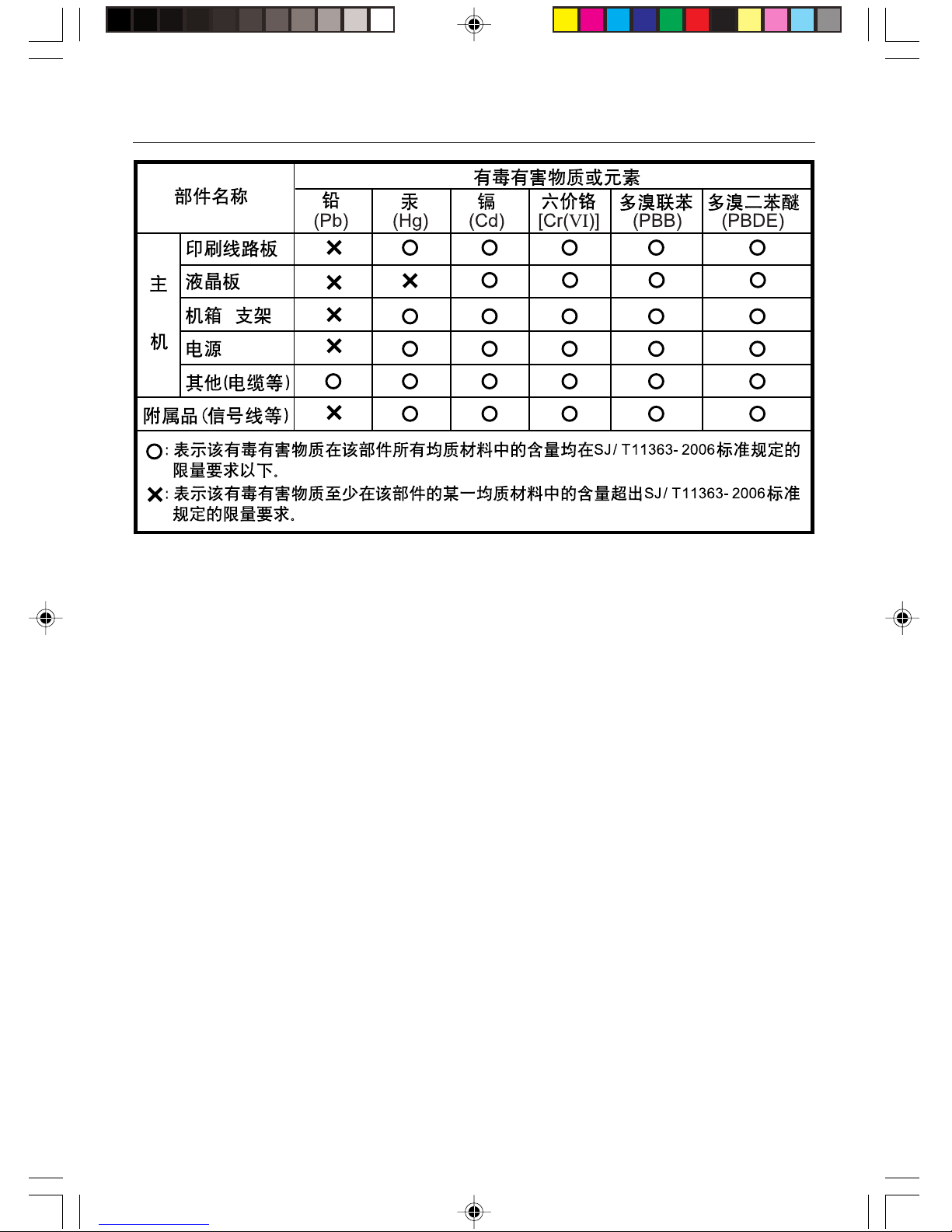
Chinese RoHS-information relevant for Chinese market
00_Cover 16/2/07, 8:00 AM4

English-1
English
Declaration of the Manufacturer
We hereby certify that the colour monitor AccuSync LCD193WM
(L196H5)/AccuSync LCD203WM (L206H6)/AccuSync LCD223WM
(L226H7) are in compliance with
Council Directive 73/23/EEC:
– EN 60950-1
Council Directive 89/336/EEC:
– EN 55022
– EN 61000-3-2
– EN 61000-3-3
– EN 55024
RISK OF ELECTRIC SHOCK • DO NOT OPEN
TO PREVENT FIRE OR SHOCK HAZARDS, DO NOT EXPOSE THIS UNIT TO RAIN OR MOISTURE. ALSO, DO NOT USE THIS UNIT’S
POLARIZED PLUG WITH AN EXTENSION CORD RECEPTACLE OR OTHER OUTLETS UNLESS THE PRONGS CAN BE FULLY INSERTED.
REFRAIN FROM OPENING THE CABINET AS THERE ARE HIGH VOLTAGE COMPONENTS INSIDE. REFER SERVICING TO QUALIFIED
SERVICE PERSONNEL.
WARNING
CAUTION: TO REDUCE THE RISK OF ELECTRIC SHOCK,
DO NOT REMOVE COVER (OR BACK). NO USER
SERVICEABLE PARTS INSIDE. REFER SERVICING
TO QUALIFIED SERVICE PERSONNEL.
This symbol warns user that uninsulated voltage
within the unit may have sufficient magnitude to cause
electric shock. Therefore, it is dangerous to make any
kind of contact with any part inside this unit.
This symbol alerts the user that important literature
concerning the operation and maintenance of this
unit has been included. Therefore, it should be read
carefully in order to avoid any problems.
CAUTION
and marked with
NEC Display Solutions, Ltd.
4-13-23, Shibaura,
Minato-Ku
Tokyo 108-0023, Japan
Contents
Your new NEC AccuSync LCD monitor box* should contain the
following:
• AccuSync LCD monitor with tilt base
• Audio Cable
• Power Cord
•Video Signal Cable
•User’s Manual
• CD-ROM
• Base Stand
• Cable Holder
*
Remember to save your original box and packing material to
transport or ship the monitor.
User’s
Manual
Audio
Cable
Power
Cord
Video Signal
Cable
Base
Stand
AccuSync LCD monitor
(base stand not connected)
CD-ROM
Quick Start
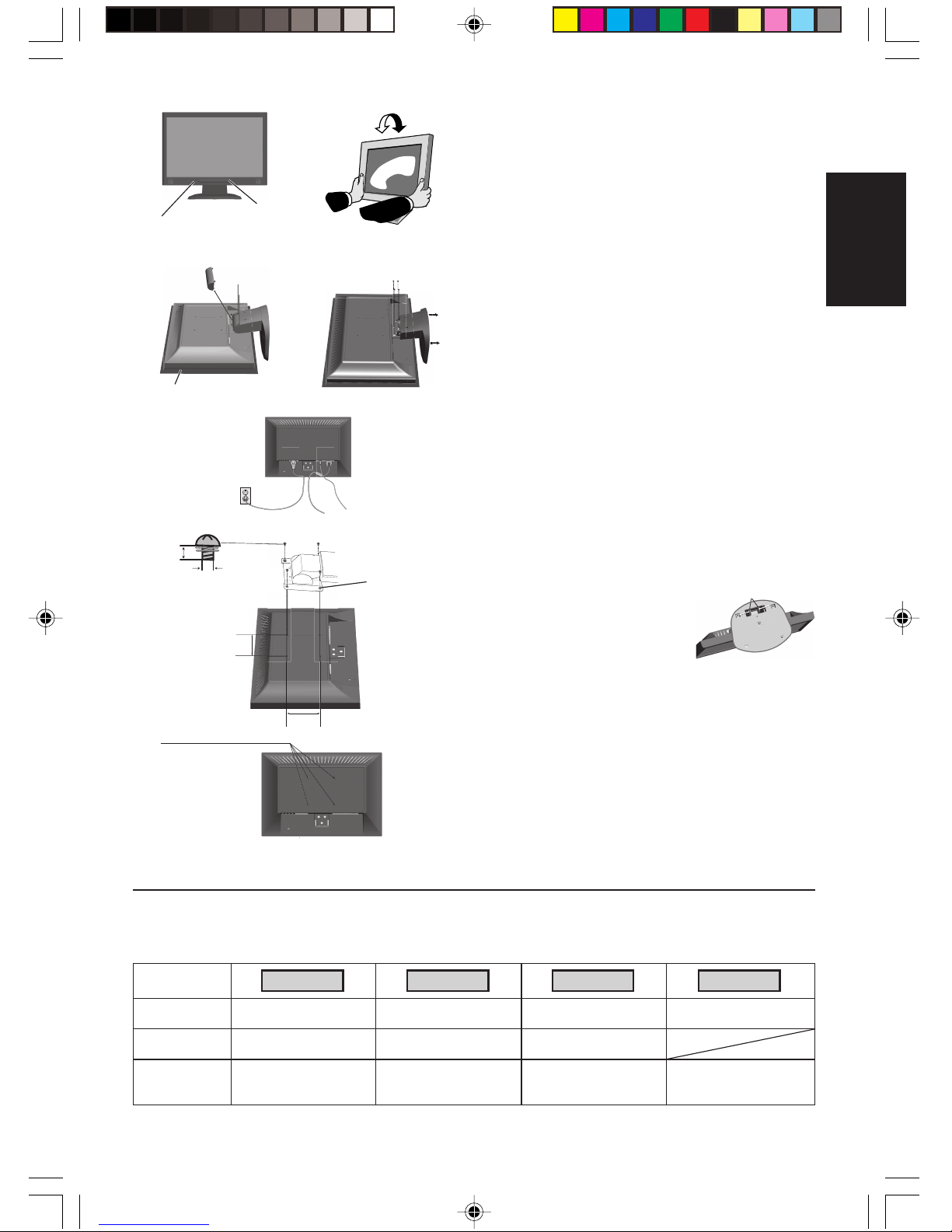
To attach the Base to the LCD Stand:
1. Attach the Base to the Stand. The locking tabs on the Stand should
fit into the hole on the centre back of the Base (Figure S.1).
To attach the Cable Holder:
1. Insert the tabs of Cable Holder into the hole of Stand and slide the
Cable Holder downward into place (Figure S.1).
NOTE: Please confirm that the tabs are completely secure.
To attach the AccuSync LCD monitor to your system, follow these
instructions:
1. Turn off the power to your computer.
2. For the PC with Analog output: Connect the 15-pin mini D-SUB
signal cable to the connector of the display card in your system
(Figure A.1). Tighten all screws.
For the Mac: Connect the MultiSync Macintosh cable adapter (not
included) to the computer. Attach the 15-pin mini D-SUB signal
cable to the MultiSync Macintosh cable adapter (Figure A.2).
Tighten all screws.
NOTE: Some Macintosh systems do not require a Macintosh cable
adapter.
3. Connect the 15-pin mini D-SUB of the video signal cable and
Audio Cable to the appropriate connector on the back of the
monitor (Figure B.1). Connect the Headphone (not included) to
the appropriate connector at the front of the monitor (Figure C.1).
4. Connect one end of the power cord to the monitor and the other
end to the power outlet. Place the Video Signal Cable and power
cord to the Cable holder (Figure B.1).
NOTE: Adjust position of cable that place under the Cable holder to
avoid damage for cable or monitor.
NOTE: Please refer to Caution section of this manual for proper
selection of power cord.
Figure S.1
Base
Locking Tabs
Stand
Figure A.1 Figure A.2
Macintosh Cable
Adapter (not included)
Cable Holder
Figure B.1
Cable Holder
Cable holder
Audio Input
Input (D-Sub)
Connect to Computer
audio output
Power Cord
01_English 16/2/07, 8:01 AM1
English-2
English
Locking tabs
Headphone
Figure C.1
Power Button
Figure TS.1
Figure R.1
Non-abrasive surface
Figure R.2
Figure R.3
4-SCREWS (M4)
(MAX depth: 10 mm)
If use other
screw, check
depth of hole.
Weight of LCD assembly: 4.3 kg - LCD193WM (MAX)
4.9 kg - LCD203WM (MAX)
5.3 kg - LCD223WM (MAX)
Specifications
Tighten all screws
100 mm
Thickness of Bracket
(Arm) 2.0 ~ 3.2 mm
Controls
OSD (On-Screen Display) control buttons on the front of the monitor function as follows:
1. Basic function at pressing each key
Showing OSD. Shortcut to Bright adjust
window.
Button
At No OSD
showing
Shortcut to Volume adjust
window.
At OSD showing
(Icon selection stage)
Go to Adjustment stage. Cursor goes to left. Cursor goes to right.
At OSD showing
(Adjustment stage)
Go to Icon selection stage. Adjust value decrease or
Cursor for adjust goes to
left.
Adjust value increase or
Cursor for adjust goes to
right.
SELECT
– +
“Auto adjust” operate.
Reset operation.
Mute off/on switch on
Volume adjustment window.
AUTO/RESET
5. Turn on the monitor with the front power button and the computer
(Figure C.1).
6. No-touch Auto Adjust automatically adjusts the monitor to optimal
settings upon initial setup for most timings.
For further adjustments, use the following OSD controls:
• Auto Adjust Contrast
• Auto Adjust
Refer to the Controls section of this User’s Manual for a full
description of these OSD controls.
NOTE: If you have any problem, please refer to the
Troubleshooting section of this User’s Manual.
Tilt
Grasp both sides of the monitor screen with your hands and adjust
the tilt as desired (Figure TS.1).
Remove Monitor Stand for Mounting
To prepare the monitor for alternative mounting purposes:
1. Disconnect all cables.
2. Remove the hinge cover (Figure R.1).
3. Place monitor face down on a non-abrasive surface (Figure R.1).
4. Remove the 3 screws (LCD193WM) or the 4 screws (LCD203WM/
LCD223WM) connecting the monitor to the stand and remove the
stand as indicated (Figure R.2).
The monitor is now ready for mounting in an alternative manner.
5. Connect the AC cord and signal cable to the back of the monitor
(Figure R.3).
6. Reverse this process to re-attach stand.
NOTE: Use only VESA-compatible alternative mounting method.
NOTE: Handle with care when removing monitor stand.
Removing the Base
NOTE: Always remove the Base when shipping
the LCD.
1. Place monitor face down on a nonabrasive surface (Figure R.1).
2. While using your fingers, press the locking tabs to unlock the
Base.
3. Pull out the unlocked Base.
Connecting a Flexible Arm
This LCD monitor is designed for use with a flexible arm.
Please use the attached screws (4pcs) as shown in the picture when
installing. To meet the safety requirements, the monitor must be
mounted to an arm which guaranties the necessary stability under
consideration of the weight of the monitor.
The LCD monitor shall only be used with an approved arm (e.g. GS
mark).
3 screws (LCD193WM) -
4 screws (LCD203WM/LCD223WM)
4 x 12 mm with lock washer
and flat washer
M4
12 mm
100 mm
01_English 16/2/07, 8:01 AM2
English-3
English
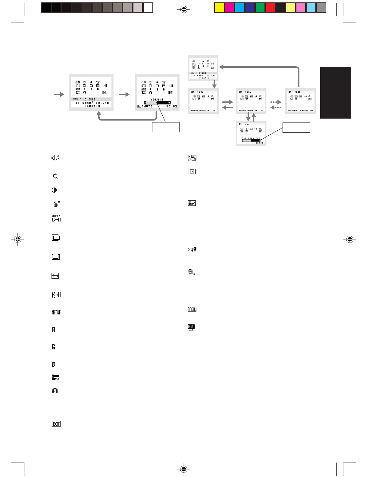
AUDIO
Controls the volume of the speakers or headphones.
To mute the speaker output, press the “AUTO/RESET” button.
BRIGHTNESS
Adjusts the overall image and background screen brightness.
CONTRAST
Adjusts the image brightness in relation to the background.
AUTO CONTRAST
Adjusts the image displayed for non-standard video inputs.
AUTO ADJUST
Automatically adjusts the Image Position, the H. Size and
Fine setting.
LEFT/RIGHT
Controls Horizontal Image Position within the display area of
the LCD.
DOWN/UP
Controls Vertical Image Position within the display area of the
LCD.
H. SIZE
Adjusts the horizontal size by increasing or decreasing this
setting.
FINE
Improves focus, clarity and image stability by increasing or
decreasing this setting.
COLOUR CONTROL SYSTEMS
Five colour presets (9300/7500/sRGB/USER/NATIVE) select
the desired colour setting.
COLOUR RED
Increase or decreases Red. The change will appear on
screen.
COLOUR GREEN
Increase or decreases Green. The change will appear on
screen.
COLOUR BLUE
Increase or decreases Blue. The change will appear on screen.
TOOL
Selecting TOOL allows you to get into the sub menu.
FACTORY PRESET
Selecting Factory Preset allows you to reset all OSD control
settings back to the factory settings. The RESET button will
need to be held down for several seconds to tage effect.
Individual settings can be reset by highlighting the control to
be reset and pressing the RESET button.
EXIT
Selecting EXIT allows you exit OSD menu/ sub menu.
LANGUAGE
OSD control menus are available in nine languages.
OSD TURN OFF
The OSD control menu will stay on as long as it is in use.
In the OSD Turn OFF submenu, you can select how long the
monitor waits after the last touch of a button to shut off the
OSD control menu. The preset choices are 10 - 120 seconds
by 5 seconds step.
OSD LOCK OUT
This control completely locks out access to all OSD control
functions without Brightness and Contrast. When attempting
to activate OSD controls while in the Lock Out mode, a
screen will appear indicating the OSD are locked out. To
activate the OSD Lock Out function, press “AUTO/ RESET”,
then “+” key and hold down simultaneously. To de-activate the
OSD Lock Out, press “AUTO/ RESET”, then “+” key and hold
down simultaneously.
RESOLUTION NOTIFIER
If ON is selected, a message will appear on the screen after
45 seconds, notifying you that the resolution is not at optimal
resolution.
EXPANSION
Selects the zoom mode.
FULL: The image is expanded to 1440 x 900 (LCD193WM) or
1680 x 1050 (LCD203WM/LCD223WM), regardless of the
resolution.
ASPECT: The image is expanded without changing the
aspect ratio.
DDC/CI
Turns ON or OFF the two way communication and control of
the monitor.
MONITOR INFO
Indicates the model and serial numbers of your monitor.
OSD Warning
OSD Warning menus disappear with SELECT button.
NO SIGNAL: This function gives a warning when there is no
signal present. After power is turned on or when there is a
change of input signal or video is inactive, the No Signal
window will appear.
RESOLUTION NOTIFIER: This function gives a warning of
use with optimized resolution. After power is turned on or
when there is a change of input signal or the video signal
doesn’t have proper resolution, the Resolution Notifier
window will open. This function can be disabled in the TOOL
menu.
OUT OF RANGE: This function gives a recommendation of
the optimized resolution and refresh rate. After the power is
turned on or there is a change of input signal or the video
signal doesn’t have proper timing, the Out Of Range menu
will appear.
2. OSD structure
Sub Menu
(Icon Select)
Press
“–” or “+”
Sub Menu (Adjust)
Press “SELECT” key
Press
“–” or “+”
Example Tool:
Press “SELECT” key
Press “SELECT” key
Main Menu (Icon Select) Main Menu (Adjust)
Press
“SELECT”
key
Press
“SELECT”
key
Press “SELECT” key
Adjust by using
“–” or “+”
Adjust by using
“–” or “+”
01_English 16/2/07, 8:01 AM3

Deutsch
Deutsch-1
Erklärung des Herstellers
Wir bestätigen hiermit, dass der Farbmonitor AccuSync LCD193WM
(L196H5)/AccuSync LCD203WM (L206H6) und AccuSync
LCD223WM (L226H7) den folgenden Richtlinien entspricht:
EG-Direktive 73/23/EG:
– EN 60950-1
EG-Direktive 89/336/EG:
– EN 55022
– EN 61000-3-2
– EN 61000-3-3
– EN 55024
STROMSCHLAGGEFAHR • NICHT ÖFFNEN
SETZEN SIE DAS GERÄT WEDER REGEN NOCH FEUCHTIGKEIT AUS, DA ES ANDERNFALLS ZU FEUER ODER STROMSCHLÄGEN KOMMEN
KANN. VERWENDEN SIE DEN NETZSTECKER DIESES GERÄTS KEINESFALLS MIT EINEM VERLÄNGERSKABEL ODER EINER
STECKDOSENLEISTE, WENN DIE STECKERSTIFTE NICHT VOLLSTÄNDIG EINGEFÜHRT WERDEN KÖNNEN.
ÖFFNEN SIE DAS GEHÄUSE NICHT, DA SICH IM INNEREN KOMPONENTEN BEFINDEN, DIE UNTER HOCHSPANNUNG STEHEN. LASSEN SIE
WARTUNGSARBEITEN VON QUALIFIZIERTEN WARTUNGSTECHNIKERN DURCHFÜHREN.
WARNUNG
VORSICHT: ENTFERNEN SIE KEINESFALLS ABDECKUNG ODER
RÜCKSEITE, DAMIT ES NICHT ZU STROMSCHLÄGEN
KOMMT. IM INNEREN BEFINDEN SICH KEINE VOM
BENUTZER ZU WARTENDEN KOMPONENTEN. LASSEN
SIE WARTUNGSARBEITEN VON QUALIFIZIERTEN
WARTUNGSTECHNIKERN DURCHFÜHREN.
Dieses Symbol weist den Benutzer auf nicht isolierte
spannungsführende Komponenten im Gerät hin, die
Stromschläge verursachen können. Aus diesem Grund
dürfen Sie keinesfalls Kontakt mit einer Komponente im
Geräteinneren herstellen.
Dieses Symbol weist den Benutzer auf wichtige
Informationen zu Betrieb und Pflege dieses Geräts hin.
Die Informationen sollten sorgfältig gelesen werden, um
Probleme zu vermeiden.
VORSICHT
und mit folgendem Siegel
gekennzeichnet ist:
NEC Display Solutions, Ltd.
4-13-23, Shibaura,
Minato-Ku
Tokyo 108-0023, Japan
Inhalt der Verpackung
Der Karton* mit Ihrem neuen NEC AccuSync LCD-Monitor sollte
folgende Komponenten enthalten:
• AccuSync LCD-Monitor mit verstellbarem Fuß
• Audiokabel
• Netzkabel
• Signalkabel
• Bedienungsanleitung
• CD-ROM
• Standfuß
• Kabelhalter
*
Bewahren Sie den Originalkarton und das Verpackungsmaterial
für spätere Transporte des Monitors auf.
Bedienung-
sanleitung
Audiokabel
Netzkabel
Signalkabel
Standfuß AccuSync LCD-Monitor
(Standfuß nicht montiert)
CD-ROM
Kurzanleitung
So befestigen Sie den Standfuß am Fuß des LCD-Monitors:
1. Befestigen Sie den Standfuß am Monitor. Die Verriegelungen an
der Unterseite des Monitors müssen in die Aussparung in der
Mitte des Standfußes einrasten (Abbildung S.1).
Gehen Sie folgendermaßen vor, um den Kabelhalter zu befestigen:
1. Stecken Sie die Verriegelungen des Kabelhalters in die
Aussparungen am Monitorfuß und schieben Sie den Kabelhalter
nach unten, bis er einrastet (Abbildung S.1).
HINWEIS: Überprüfen Sie bitte, dass der Schnappverschluss
richtig eingerastet ist.
Gehen Sie folgendermaßen vor, um den AccuSync LCD-Monitor an
Ihr System anzuschließen:
1. Schalten Sie Ihren Computer aus.
2. PC mit analogem Ausgang: Verbinden Sie den Mini-D-SUBStecker (15 Stifte) des entsprechenden Signalkabels mit dem
Anschluss der Grafikkarte in Ihrem System (Abbildung A.1).
Ziehen Sie die Schrauben fest.
Mac: Schließen Sie den MultiSync-Kabeladapter für Macintosh
(nicht mitgeliefert) an den Computer an. Stecken Sie den Mini-DSUB-Stecker (15 Stifte) des Signalkabels in den MacintoshKabeladapter (Abbildung A.2). Ziehen Sie die Schrauben fest.
HINWEIS: Für einige Macintosh-Systeme ist kein Macintosh-
Kabeladapter erforderlich.
3. Stecken Sie den Mini-D-SUB-Stecker (15 Stifte) des
Videosignalkabels und das Audiokabel in die entsprechenden
Buchsen auf der Rückseite des Monitors (Abbildung B.1). Stecken
Sie den Kopfhöhrer (nicht mitgeliefert) in die entsprechende Buchse
auf der Vorderseite des Monitors (Abbildung C.1).
4. Stecken Sie ein Ende des Netzkabels in den Monitor und das
andere Ende in die Steckdose. Führen Sie das Signalkabel und
Netzkabel durch den Kabelhalter (Abbildung B.1).
HINWEIS: Bringen Sie die Kabel so unter der Kabelabdeckung an, dass
weder Kabel noch Monitor beschädigt werden können.
HINWEIS:
Beachten Sie zur Auswahl des richtigen Netzkabels den
entsprechenden Sicherheitshinweis in dieser Bedienungsanleitung.
Kabelhalter
Abbildung A.1 Abbildung A.2
MacintoshKabeladapter
(nicht mitgeliefert)
Abbildung S.1
Standfuß
Verriegelungen
Monitorfuß
Kabelhalter
Abbildung B.1
Kabelhalter
Audioeingang
Eingang (D-Sub)
An Audio-Ausgang des
Computers anschließen
Netzkabel
02_German 16/2/07, 8:01 AM1
 Loading...