

Page 1
Qube 300
Installation Manual
Page 2

Qube 300 | Installation Manual
Disclaimer
It is the Owner’s sole responsibility to install and use the Qube 300 (the Product) in a manner that will not
cause accidents, personal injury or property damage. For the purpose of this notice, “Owner”, “you” and
“your” means the party (including any person authorized by that party to use and/or install the Product) that
has either: (a) purchased the Product; or (b) leased the Product from Navman Wireless or its related
companies. The Owner of this Product is solely responsible for observing safe driving practices.
The choice, location and installation of all components of the Product is critical. If installation is not correct,
the Product may not perform at its designed potential or specifications. Ensure that any mounting holes that
need to be cut in the vehicle will not weaken the vehicle structure or compromise the safety of the vehicle or
its occupants. If in doubt, consult the vehicle manufacturer, or your Navman Wireless dealer.
TO THE MAXIMUM EXTENT PERMITTED BY LAW, ALL REPRESENTATIONS AND WARRANTIES (EXCEPT ANY
WHICH MAY NOT LAWFULLY BE EXCLUDED) ARE, EXPRESSLY EXCLUDED, INCLUDING WITHOUT
PREJUDICE TO THE, GENERALITY OF THE FOREGOING, THE IMPLIED WARRANTIES OR MERCHANTABILITY
AND FITNESS FOR A PARTICULAR PURPOSE. TO THE MAXIMUM EXTENT PERMITTED BY LAW NAVMAN
WIRELESS DISCLAIMS ALL LIABILITY ARISING OUT OF OR IN CONNECTION WITH THE PRODUCT
(INCLUDING ANY USE OF THIS PRODUCT IN A WAY THAT MAY CAUSE ACCIDENTS, DAMAGE OR VIOLATE
THE LAW).
As Navman Wireless is continuously improving this Product, Navman Wireless may make changes to the
Product at any time which may not be reflected in this document. Please contact your nearest Navman
Wireless office if you require any further assistance.
NAVMAN WIRELESS DISCLAIMS ALL LIABILITY FOR ANY USE OF THIS PRODUCT IN A WAY THAT MAY
CAUSE ACCIDENTS, DAMAGE OR VIOLATE THE LAW.
EMC Compliance
This device complies with Part 15 of the FCC Rules. Operation is subject to the following two conditions: (1)
This device may not cause harmful interference, and (2) this device must accept any interference received,
including interference that may cause undesired operation.
Copyright
© 2014 Navman Wireless Holdings L. P. Navman Wireless is a registered trademark of Navman Wireless
Holdings L. P. All rights reserved. All other trademarks and registrations are the property of their respective
owners.
Page 3

Qube 300 | Installation Manual
Contents
Disclaimer ...................................................................................................................................... 2
1 Introduction ............................................................................................................................ 4
1.1 Overview .................................................................................................................................. 4
1.2 Audience ...................................................................................................................................... 4
2 Qube 300 Hardware ................................................................................................................ 5
2.1 Box Contents ............................................................................................................................ 5
2.2 Other Components Required ......................................................................................................... 5
3 Mounting Locations ................................................................................................................. 6
3.1 Antenna Mounting Location ....................................................................................................... 6
3.2 Qube 300 Mounting Location ......................................................................................................... 6
4 Installation & Wiring ............................................................................................................... 8
4.1 Before Starting ......................................................................................................................... 8
4.2 3-Wire Basic Tracking & Antenna Connections ................................................................................ 8
4.3 Connect Any Auxiliary Devices ....................................................................................................... 9
4.4 Connect Any Optional Sensors ..................................................................................................... 11
4.5 Install the Security Cover ............................................................................................................ 13
4.6 Mount the Qube 300 ................................................................................................................... 13
5 Testing and Fault Finding ...................................................................................................... 14
5.1 Check the Ignition Connection ..................................................................................................... 14
5.2 Check Data and GPS Reception ................................................................................................... 14
5.3 Fault Finding .............................................................................................................................. 14
6 Dimensions ............................................................................................................................ 15
7 Specifications ........................................................................................................................ 16
8 Contacts ................................................................................................................................ 17
Page 4

Qube 300 | Installation Manual
1 Introduction
1.1 Overview
The Navman Wireless Qube 300 is an Automatic Vehicle Location unit (AVL) that is installed into fleet
vehicles. It communicates with a server and allows vehicle information to be stored and monitored.
It is a combined GPS (Global Positioning System) and communications product that contains:
a GPS Receiver to provide accurate location data,
a Cellular Modem that enables data to be transferred between the vehicle and the server,
an on-board microprocessor to allow data processing and storage, and external communication.
1.2 Audience
This Installation Manual is written for a professional vehicle technician. Navman Wireless welcomes your
feedback. To contact us or to visit our website, see section 8.
Page 5
Qube 300 | Installation Manual
2 Qube 300 Hardware
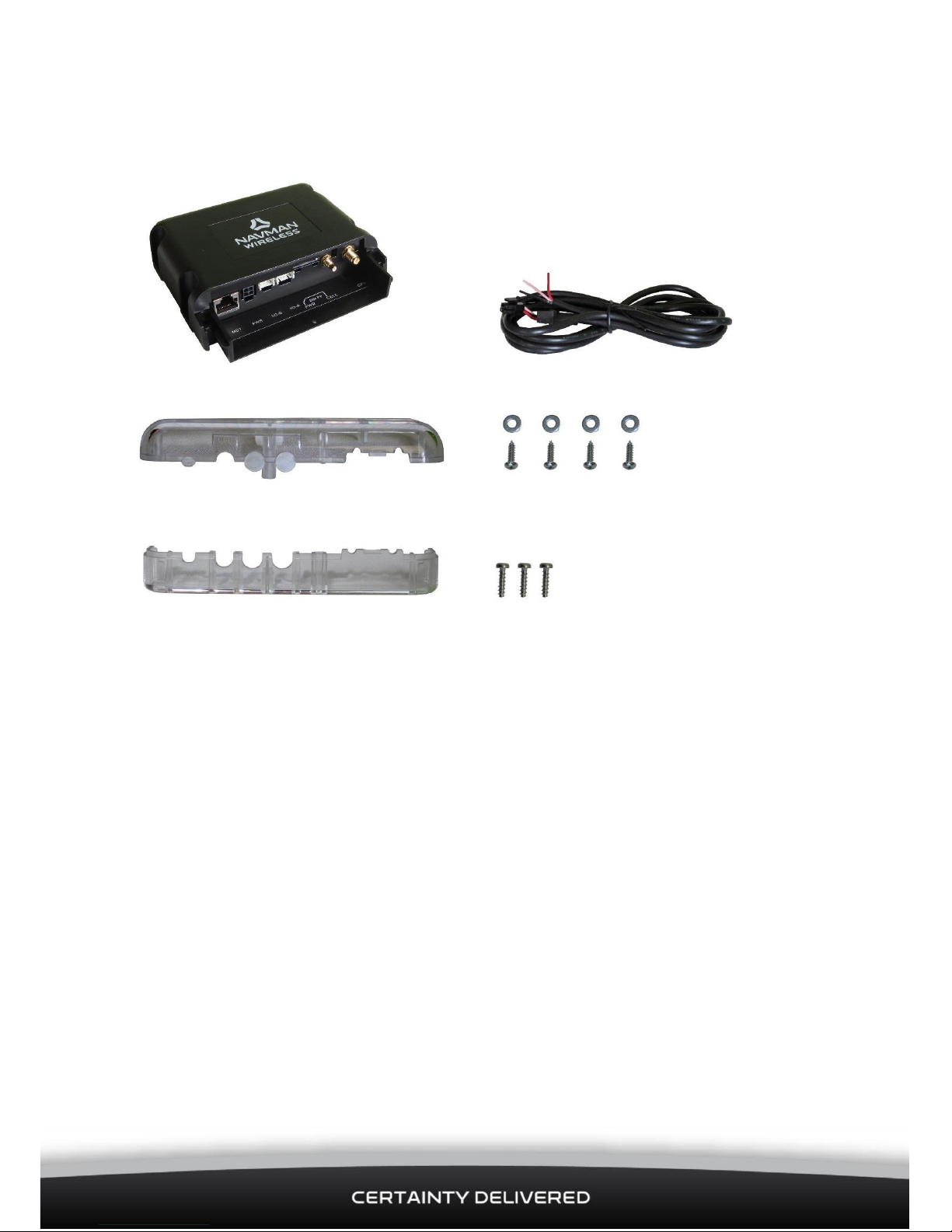
2.1 Box Contents
Qube 300 3-Wire power cable (1.9 m)
Clear plastic security cover (upper part) 4 self-tapping mounting screws AND 4
washers
Clear plastic security cover (lower part) 3 screws for the security cover
2.2 Other Components Required
You will also need the following components before starting the installation:
GPS Antenna
Cellular Antenna
To allow for quicker and easier installations, Navman Wireless recommends the use of the combination
antenna that includes both GPS and cellular components built into same housing (SAP#10001358).
Note: You can use a combi-antenna OR a separate GPS Antenna and a separate Cellular Antenna.
Contact your Navman Wireless dealer for advice on the best choices for your type of installation and for
ordering information, if necessary.
Depending on the installation requirements, you may also need the following components:
8-Wire I/O cable (SAP#10001294)
10-Wire I/O cable (SAP#10001293)
Navman Wireless digital temperature probes (and Installation Manual)
Satellite Modem cable (SAP#10001311)
Note: The 3-Wire Power cable, the GPS Antenna, and the Cellular Antenna are the minimal requirement for
tracking only.
Page 6

Qube 300 | Installation Manual
3 Mounting Locations
3.1 Antenna Mounting Location
CAUTION
The antenna must be at least 20 cm (8”) from any person to meet FCC RF exposure requirements.
3.1.1 Exposed Antenna Installation
• Using the supplied double-sided tape pad, mount the antenna in the upper or lower corner of the
vehicle’s windshield. Tuck the wires behind the A-pillar panel and run under the dash to the Qube’s
location.
3.1.2 Covert Antenna Installation
• Using the supplied double-sided tape pad, mount the antenna to a flat clean surface under the
dashboard and positioned horizontally. Make sure the correct side of antenna is facing up.
• Do not mount the GPS antenna under any metal structure or near the vehicle’s radio. Avoid
mounting the antenna under dashboard in areas where metal clipboards, laptops, loose change, etc.
may be placed on top of the dash. These items may inadvertently block the GPS signal to the
antenna.
Fleet manager will need to determine the appropriate method (exposed or covert) for mounting the antenna.
Note: The combination antenna (SAP#10001358) is not waterproof – do not mount outside of the vehicle.
Use of an antenna that is not approved by Navman Wireless, or antenna installation that is contrary to the
recommendations provided by the antenna manufacturer or Navman Wireless may result in poor GPS or
cellular performance, and may invalidate the product warranty.
3.2 Qube 300 Mounting Location
Choose a suitable mounting location for the Qube 300, using the following guidelines, but do NOT install the
Qube 300 until advised.
The installation is considered to be permanent as the firmware can be updated without removing the Qube
300 from the vehicle.
IMPORTANT NOTICE
The Qube 300 contains an accelerometer that detects movement. It is critical that the Qube 300 is
mounted securely and cannot move independently of the vehicle OR vibrate off its mounting location.
Insecure mounting of the Qube 300 may result in false or incorrect vehicle movement alerts.
Page 7

Qube 300 | Installation Manual
The installation location must:
be a rigid surface or a large wiring loom, where the Qube 300 can be firmly secured
be dry
allow MDT/M-Nav or other peripheral device connections
allow the diagnostic LEDs on the Qube 300 to be seen
not be subject to excessive vibration or excessive heat
not be visible to the driver
The final orientation of the Qube 300 after installation is not important.
The following locations within the vehicle may be suitable:
inside or underneath the dash
in the boot/trunk area
CAUTION
Ensure that any holes that need to be drilled in the vehicle will not weaken the vehicle structure or
compromise the safety of the vehicle or its occupants. If in doubt, consult the vehicle manufacturer.
If mounting holes are required, use grommets to ensure that the vehicle remains waterproof.
Page 8

Qube 300 | Installation Manual
4 Installation & Wiring
4.1 Before Starting
Check that all cables are long enough to reach between the chosen Qube 300 location, the antenna location,
and the ignition loom (or fuse box).
Test the proposed antenna location to check whether it will give the best performance.
Check that the SIM Card has been installed into the Qube 300 (see Section 4.3 for the location).
4.2 3-Wire Basic Tracking & Antenna Connections
The 3-Wire Power cable, a GPS Antenna, and a Cellular Antenna, are the minimal requirements for tracking
only.
Ensure that all cables are:
tidy and secure, and do not present a hazard to the users of the vehicle/asset
protected from chaffing on sharp edges
connected to manufacturer’s approved points
located where they will not be damaged
Pin
3-Wire Colour
Function
Description
1
Black
GND
Vehicle Ground/chassis connection.
2
Red
+12/24V DC
Main power connection (main vehicle supply). This
connection must be fused (3 Amp Slow Blow).
4
Pink
Ignition Detect
Positive input from vehicle when the key is in the IGNITION
position (not the Accessory position).
This signal must remain ON during engine cranking / startup. This connection must be fused (3 Amp Slow Blow).
CAUTION
Ensure that any connection to the vehicle wiring system does not interfere with the operation of the
vehicle or with any of the vehicle’s safety systems. If in doubt, consult the vehicle manufacturer.
Use insulation tape to insulate any bare wires that are not connected.
Wiring the unit incorrectly or leaving any bare wires exposed may result in electrical damage to the Qube
300 or the vehicle’s electrical system.
Page 9

Qube 300 | Installation Manual
Check that the SIM Card is
4.3 Connect Any Auxiliary Devices
The Qube 300 has 3 serial ports. Use these to connect to other Navman Wireless devices, such as an M-Nav
or MDT, or to third-party equipment for serial data communication. The Qube 300 also has several digital
and analogue I/O lines which can be connected to external sensors or equipment, using optional I/O cables
as follows:
Connection to the serial port 1 is made through the RJ45 Connector (MDT) at position 1,
8-Way Expansion Connector (I/O-B) at position 3,
10-Way Expansion Connector (I/O-A) at position 4
RJ45 Connector:
Pin
Function
Description
1
GND
Ground
2
+12/24 V DC
Power Supply
3
RTS-1
Serial Port 1 (Input) Ready To Send Flow Control
4
RXD-1
Serial Port 1 (Input) Data
5
TXD-1
Serial Port 1 (Output) Data
6
CTS-1
Serial Port 1 (Output) Clear To Send Flow Control
8-Way Expansion Connector:
Pin
Wire Colour
Function
Description
1
Black
GND
Ground Output
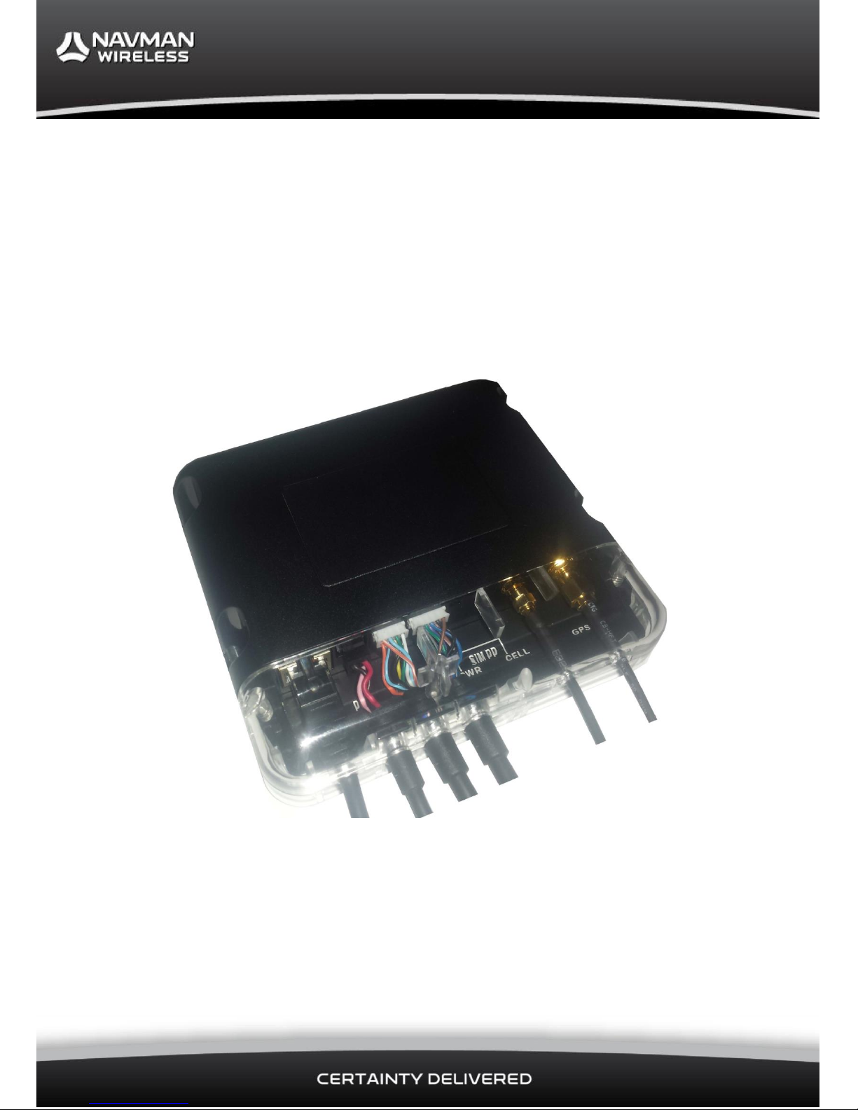
inserted at position 5 (HSPA
units only).
Screw the Cellular Antenna
connector to the CELL connector
at position 6.
Screw the GPS Antenna
connector to the GPS connector
at position 7.
Insert the 3-Wire Power cable
to the 4-Way PWR connector at
position 2.
If there are NO auxiliary devices or sensors
to be connected, proceed to section 4.5.
If you need to connect any auxiliary
Devices or sensors, proceed to section 4.3.
1 2
3 5 6 4
7
Page 10

Qube 300 | Installation Manual
2
White
+3.8V DC
Reference for Analogue Input
3
Yellow
Multi I/O-1
Digital Input OR Digital Output OR Analogue Input 1
(Also Wake from Sleep)
4
Green
Multi I/O-2
Digital Input OR Digital Output OR Analogue Input 2
5
Light Blue/Black
RXD-2
RS232 Serial Port 2 Data Input
6
Light Blue
TXD-2
RS232 Serial Port 2 Data Output
7
Orange
1 W+
Temperature Probe Power Supply
8
Orange/White
1 WD
Temperature Probe Data
10-Way Expansion Connector:
Pin
Wire Colour
Function
Description
1
Black
GND
Ground Output
2
Brown
TXD-3
RS232 Serial Port 3 Data Output
3
Brown/White
RXD-3
RS232 Serial Port 3 Data Input
4
Black
GND
Ground Output
5
Purple
DI-4
Digital Input 4 (Active High/Low) (Wake from Sleep and
RPM Count)
6
Blue
DI-3
Digital Input 3 (Active High/Low) (Wake from Sleep)
7
Blue/White
DI-2
Digital Input 2 (Active High/Low) (Wake from Sleep)
8
Green/White
DI-1
Digital Input 1 (Active High/Low) (Wake from Sleep)
9
Light Green
DO-1
Digital Output 1 (Active Low only)
10
Grey
DO-2
Digital Output 2 (Active Low only)
Wake from sleep configuration
Wake from sleep can be triggered on MIO-1 Active HIGH ONLY and on DI-1 thru DI-4 in either an Active
HIGH or Active LOW configuration.
When the event is triggered the Qube300 will fully boot up, send any sensor events triggered and after 5
mins return to sleep mode.
Note: If a senor input line is configured for read with ignition on only, Qube300 will boot up but not send
sensor events.
Page 11

Qube 300 | Installation Manual
4.4 Connect Any Optional Sensors
4.4.1 Digital Inputs DI-1 to DI-4
The Digital Inputs can be configured to detect high voltages (Active High) OR low voltages (Active Low).
Active High Input Configuration
When configured as an Active High Input, the input state is considered ON when it becomes high. The
voltage thresholds that trigger the change in the input state are as follows:
State
Voltage
High
>5.0V
Low
<1.0V/Disconnected
Active Low Input Configuration
When configured as an Active Low Input, the input state is considered ON when it becomes low. The voltage
thresholds that trigger the change in input state are as follows:
4.4.2 Digital Outputs DO-1 & DO-2
The Digital Outputs will pull to Ground and sink a maximum current of 250 mA when activated.
The outputs have over-current trip protection and, if tripped, the output must be changed to OFF or have a
power cycle to reset the current trip.
State
Voltage
High
>0.5V
Low
<0.2V/Disconnected
Page 12

Qube 300 | Installation Manual
4.4.3 Multi I/O-1 & I/O-2
Each Multi I/O can be configured in one of 3 different operating modes:
Digital Input
Digital Output
Analogue Input
Note: When the Satellite Modem functionality is enabled, Multi I/O-2 cannot be used.
Digital Input
When configured for Digital Input, Multi I/O-1 and Multi I/O-2 can only operate as Active High Inputs, with
the Active High functionality and wiring as described in section 4.4.1.
Digital Outputs
When configured for Digital Output, Multi I/O-1 and Multi I/O-2 operate as described in section 4.4.2.
Analogue Inputs
When configured for Analogue Input, Multi I/O-1 and Multi I/O-2 connect to devices that have a variable
voltage output.
The input voltage range is 0–33 V DC. If the input voltage range exceeds 33 V DC, the input must be scaled.
To scale the voltage correctly, calculate the maximum sensor voltage to scale to the max 33 V DC at the
Analogue Input.
4.4.4 Navman Wireless Temperature Probes
The Qube 300 can support up to six Navman Wireless digital temperature probes and can also use some of
the Multi I/O and Digital Inputs for temperature event monitoring. See the Qube 300 & Navman Wireless
Temperature Probes Installation Manual for installation instructions.
Page 13

Qube 300 | Installation Manual
4.5 Install the Security Cover
IMPORTANT NOTICE
You cannot plug or unplug any cables after the tamper-proof security cover has been installed. To change
cable configuration, tamper-proof security cover must be removed.
When all the wiring is complete, you must install the tamper-proof security cover. This has an upper part
and a lower part.
Slide the lower part under the cables and push into place onto the lower front part of the Qube 300. The
screw pillar should align with the screw hole in the Qube 300.
Fit the cables for your wiring configuration into the appropriate slots on the lower part, as shown:
Angle the upper part of the security cover onto the front of the Qube 300 then push it down into place. The
upper and lower parts of the security cover should fit snugly together with no gap between them. The two
screw holes at the sides of the Qube 300 should align with the two screw pillars at the sides of the security
cover.
Working from underneath the Qube 300, insert the three security screws into the three screw pillars and
screw into place. Tighten using a Torx T10 security screwdriver.
The example on the front cover shows a completed Qube 300 installation with all cable options connected.
4.6 Mount the Qube 300
Mount the Qube 300 securely at your chosen installation location using the four self-tapping screws provided
or cable ties. Place these through the slots along both sides of the Qube 300.
The upper part has three plastic slot covers that can be broken out to match your wiring configuration:
10 - W
ire I / O cable
MDT/M
-
Nav
or S erial RS232
cable
3 - W
ire P ower
cable
GPS
Antenna
cable
Cellular
Antenna
cable
8 - Wire
I/O
cable
Break out ONLY
for an 8 - W
ire I /
O cable
. Break out ONLY
for
an
MDT/M
-
Nav
or
Serial RS232
cable
. Break out ONLY
for a 10 - W
ire I /
O cable
.
Page 14

Qube 300 | Installation Manual
5 Testing and Fault Finding
5.1 Check the Ignition Connection
Use a multi-meter to measure the voltage at the ignition wire connected to the Qube 300, as follows:
1. Turn the key to the ACCESSORY position. Check that there is no voltage on the ignition line.
2. Turn the key to the IGNITION position. Ensure that 12/24 V DC is present on the ignition line.
3. Watch the meter and start the vehicle, to ensure that the voltage remains ON during start-up.
If any of these tests fail, the Qube 300 is not connected to the correct supply. Please find the correct wire.
5.2 Check Data and GPS Reception
1. The vehicle must be outside, in a location where the GPS Antenna has a clear view of the sky and
there is good cellular coverage.
2. Turn the ignition key to the IGNITION position.
3. Check that all three LED indicators on the Qube 300 turn ON. This may take up to 15 minutes but
normally takes less than 2 minutes.
5.3 Fault Finding
Qube 300 Fault
Resolution
Green Power LED is OFF
Check Ignition is ON.
If Ignition is ON but the Green Power LED is OFF, check that the Battery
and Ignition supply are connected with the correct voltages present and
the Qube 300 has a good negative/ground connection.
Orange GPS LED is blinking
(no fix)
Ensure that the GPS Antenna is positioned correctly and has a clear view
of the sky.
Ensure that the GPS Antenna is screwed in fully on the Qube 300.
Try another GPS Antenna.
Red Cellular LED is blinking
(no connection)
Check that the SIM card is inserted fully and is round the right way.
Check that the cellular network used by the Qube 300 provides cellular
coverage for your current geographic location.
Contact Navman Wireless (see section 8) to confirm that the SIM card is
registered on the telecommunications network.
Page 15

Qube 300 | Installation Manual
6 Dimensions
Page 16

Qube 300 | Installation Manual
7 Specifications
Physical
• Weight: 320 g
• Packed Weight (Gift Box): 600 g
• Case Material: Bayer KU2 1514
ABS/Polycarbonate blend
• Tamper Cover: Polycarbonate
Power Supply
• Nominal operating voltage: 12 or 24 V
vehicle supplies
• Minimum operating voltage: 8 V DC
• Maximum operating voltage: 30 V DC
Current Consumption at 13.8 V (27.6 V)
• Sleep State: <3 mA @ 12 V DC
• Awake, modem ON: 70 mA (35 mA)
• Awake, average transmit event once
every one minute: 120 mA (60 mA)
• Peak transmit current: 250 mA (130
mA)
• Battery charging: additional 150 mA (80
mA)
Digital Inputs
• Input Voltage LOW: <1.0 V (Active High
mode) Input Voltage HIGH:
>5.0 V (Active High mode) Input
Voltage LOW: <0.2 V (Active Low
mode)
• Input Voltage HIGH: >0.5 V or not
connected (Active Low mode)
• Absolute Maximum Voltage: 33 V
(Independent of supply)
Analogue Input
• Voltage Range: 0-33 V DC
• ADC Resolution: 12 bit
• Absolute Maximum Voltage: 40 V DC
Digital Output
• Maximum sink current 250 mA (over
current protection/shut-off)
Temperature Monitoring
• Maximum of six Navman Wireless digital
temperature probes
• Maximum 30 m cable length per
installation
EMC Compliance
• EN 301 489-7 V1.3.1 (2002-08)
• EN 301489-19 V1.2.1 2002
• AS/NZS CISPR 22.2006
• AS/ANZ 60950. 1:2003 Amdt 1:2006
Amdt 2:2008 Amdt 3:2008
• ISO 7637-3:1995, ISO 7637-2:2004,
ISO11452:2004, ISO 11452-4:2005
• FCC: Part 15 class A & B
Serial Interface
• RS232 x 3
Environmental
• Storage Temperature: -40 to +85°C
(-40 to +185°F)
• Operational Temperature: -20 to +70°C
(-4 to +158°F)
• IP Rating: IP4X
• Humidity: SAE J1455 Vibration: SAE
J1455
• Shock: 20G 10mS
Ignition Input
• Absolute Maximum Voltage: 33 V
(independent of supply)
Page 17

Qube 300 | Installation Manual
8 Contacts
Navman Wireless UK
Innovation Centre 2, Keele University Science
Park, Staffordshire, ST5 5NH, UK
Tel: +44 (0) 1782 55 79 50
Fax: +44 (0) 1782 55 79 79
Email: support@navmanwireless.co.uk
Website: www.navmanwireless.co.uk
Navman Wireless USA
2701 Patriot Boulevard, Suite 150
Glenview, IL 60026, USA
Tel: +1 (866) 527-9896
Fax: +1 (847) 729-5988
Email: us.support@navmanwireless.com
Website: www.navmanwireless.com
Navman Wireless Australia
Ground Floor, 16 Giffnock Avenue
Macquarie Park NSW 2113, Sydney, Australia
Tel: +61 2 9886 8500
Fax: +61 2 9887 2481
Email: info@navmanwireless.com.au
Website: www.navmanwireless.com.au
Navman Wireless NZ
7-11 Kawana Street, Northcote,
PO Box 340-184, Birkenhead 0746
Auckland, New Zealand
Tel: 0800 GPS FLEET (0800 477 353)
Email: info.nz@navmanwireless.com
Website: www.navmanwireless.co.nz
Navman Wireless Scandinavia
Kometvej 10, DK-6230, Rødekro, Danmark
Tel: Danmark: +45 70 269 732
Tel: Sweden: +46 8 559 21 916
Tel: Finland: +35 89 2316 3595
Navman Wireless Italy
Via Rudone 23rd, Rovato 25,038, Italia
Tel: +39 030 615 6468
Website: www.navmanwirelessitaly.it
Navman Wireless Taiwan
#3, 25Fl., No.508, Sec.5 Zhongxiao E. Rd,
Dist. Taipei 110, 11083, Taiwan
Tel: +886 0 2 2728 2818
Fax: +886 0 2 2728 2816
Email: support_tw@navmanwireless.com
Website: www.navmanwireless.com.au
Navman Wireless China
#911, No. 83, New Town Center, Loushanguan Rd,
Changning District, Shanghai, 200336, China
Tel: +86 0 21 3218 1056
Fax: + 86 0 21 3218 1052
Email: support_cn@navmanwireless.com
Website: www.navmanwireless.cn
Navman Wireless de México
Calzada San Pedro #100, Col. del Valle,
Pedro Garza García, Nuevo Léon. CP 66220,
México
Teléfono: +52(81) 8248.4600 ext 1001
Email: soporte@navmanwireless.com
Website: www.navmanwireless.com.mx
Page 18

Qube 300 | Installation Manual
 Loading...