

Page 1

Nautilus® U624/U626 (Model Year 2014)
Upright Bikes Service Manual
Table of Contents
Important Safety Instructions 2
Safety Warning Labels and Serial Number 3
Reading the Product Specication Label 3
Specications 3
Maintenance 4
Leveling the Machne 5
Moving the Machine 5
Troubleshooting 6
Console Service Mode 8
Maintenance Parts Exploded View 10
Replacement Procedure Skill Level 12
Mechanical Procedures 13
Belt Tension Adjustment 13
Set the Brake Tension (Calibration) 16
Service Manual
8008323.040115.A
Part Replacement 19
Console 19
Pedals 21
Crank Arms – U626 23
Transport Wheels, Front Endcaps and Footpads 27
Shrouds 29
Handlebar Assembly 34
Console Mast 37
Data Cable in the Mast 41
Brake Assembly 44
Servo Motor 46
Drive Belt and Flywheel Assembly 50
Belt Tensioner Assembly (Idler Assembly) 53
Drive Pulley Assembly (Crank Assembly) – U624 55
RPM Sensor (Speed Sensor) 58
Power Inlet 60
Nautilus, Inc., www.NautilusInc.com - Customer Service: technics@nautilus.com | 18225 NE Riverside Parkway, Portland, OR 97230 USA | © 2014 Nautilus, Inc. | ® indicates trademarks
registered in the United States. These marks may be registered in other nations or otherwise protected by common law. Polar® and Bluetooth® are registered trademarks of their
respective owners.
ORIGINAL DOCUMENT - ENGLISH VERSION ONLY
1
Page 2
Important Safety Instructions and General Troubleshooting
Information for the Nautilus
NOTICE: This document provides important safety instructions, adjustments, and general troubleshooting information for the maintenance of the Nautilus® U624 and
U626 Upright Bikes.
If you need assistance, please contact your local distributor. To find your local distributor, go to: www.nautilusinternational.com
®
U624/U626 Bikes
Service Procedures
8008329.040115.A
This icon means a potentially hazardous situation which, if not avoided, could result in death or serious injury. Read and understand all Warnings
on this machine.
Nautilus, Inc., , www.NautilusInc.com - Customer Service: technics@nautilus.com | © 2014 Nautilus, Inc. | ® indicates trademarks registered in the United States. These marks may be registered in other nations or otherwise protected by common law. Polar® and Bluetooth® are registered trademarks of their respective owners. | ORIGINAL DOCUMENT - ENGLISH VERSION ONLY
Important Safety Instructions
This icon means a potentially hazardous situation which, if not avoided, could result in death or serious injury. Read and understand all
Warnings on this machine.
Before servicing or using this equipment, obey the following warnings:
Read and understand the Service Manual before working on the machine. Failure to obey the instructions and safety warnings could
cause injury to the service technician or bystanders.
• Keep bystanders and children away from the product being serviced at all times.
• Make sure that the repair is done in an appropriate work space away from foot trafc and exposure to bystanders.
• Some components of the equipment can be heavy or awkward. Enlist the service of a second person when you do maintenance steps involving
these components. Do not try to do heavy or awkward steps on your own.
• If replacement parts are necessary, use only genuine replacement parts and hardware supplied by Nautilus. Failure to use genuine replacement
parts can cause a risk to users, keep the machine from operating correctly and void the warranty.
• Be sure that all warning stickers and instructional placards applied to the product stay present and in good condition when doing maintenance or
replacing components. If necessary, request replacement warning stickers or placards from your local distributor.
• Do not try to change the design or functionality of the machine being serviced as this can adversely affect user safety.
• Do not put the machine back in service until all shrouds, instructions, warning labels and correct functionality have been veried and tested for
correct performance.
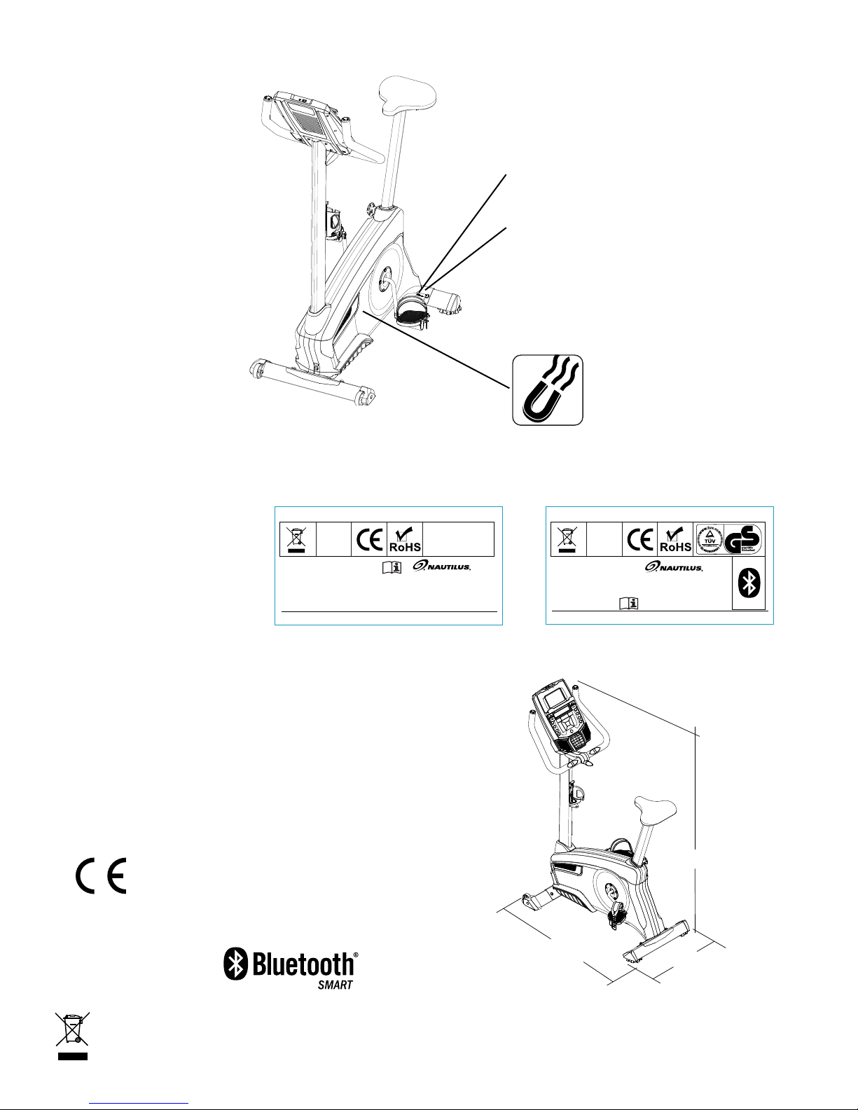
• This product contains magnets. Magnetic elds can interfere with the normal use of certain medical devices at a close range. Users may come
into proximity of the magnets in the assembly, maintenance, and/or use of the product. Given the obvious importance of these devices, such as
a pacemaker, it is important that you consult with your medical provider in connection with the use of this equipment. Please consult the “Safety
Warning Labels and Serial Number” section to determine the location of the magnets on this product.
2
Page 3
Safety Warning Labels and Serial Numbers
REVISIONS
ECO
REVISION
REV DESCRIPTION
A RELEASE TO PRODUCTION
001060 LSEVIER
58mm
30mm
REVISIONS
ECO
REVISION
REV DESCRIPTION
A RELEASE TO PRODUCTION
001060 LSEVIER
58mm
30mm
Serial number
Reading the Product Specification Decal
The Manufacture Date on the Product Specication Decal is a date code: YY/WW (year/week).
Product
specification
Manufacture Date Code:
ISO
20957
compliant
Brand: NAUTILUS Model: U624
Electrical Rating: 9V DC, 1.5A
Accuracy Class: C
Usage Class: H / Consumer use only.
Maximum User Weight: 136kg (300lb)
Equipment Type: Fitness
Made in: China
Patent: www.nautilusinc.com/IP
YYWW
Specifications
Maximum User Weight: 136 kg (300 lb)
Total Surface Area (footprint) of equipment: 5720 cm2 (902.9 in2)
Machine Weight: U624: 30.9 kg (68.1 lb)
U626: 31.1 kg (68.6 lb)
Power Requirements:
Operational Voltage: 9 VDC
Operating Current: 1.5A
AC Power Adapter: 220V - 240V AC, 50Hz
Complies with the following:
ISO 20957 compliant.
Connectivity:
U626 only:
Nautilus, Inc.
18225 NE Riverside Parkway,
Portland, Or. 97230
www.nautilusinternational.com
Phone:1-800-NAUTILUS
8004288_A
Manufacture Date Code:
Brand: NAUTILUS Model: U626
Electrical Rating: 9V DC, 1.5A
Accuracy Class: C
Usage Class: H /Consumer use only.
Max User Weight:136kg (300lb)
Equipment Type: Fitness
Made in: China
Patent: www.nautilusinc.com/IP
104cm (41.8”)
ISO
20957
compliant
YYWW
Nautilus, Inc.
18225 NE Riverside Pkwy,
Portland, Or. 97230
www.nautilusinternational.com
Phone:1-800-NAUTILUS
®
146cm (57.6”)
55cm (21.6”)
8004287_A
DO NOT dispose of this product as refuse. This product is to be recycled. For proper disposal of this product,
please follow the prescribed methods at an approved waste center.
3
Page 4

Maintenance
WARNING
DANGER
Read all maintenance instructions fully before you start any repair work. In some conditions, an assistant is necessary to
do the necessary tasks.
Equipment must be regularly examined for damage and repairs. The owner is responsible to make sure that regular
!
maintenance is done. Worn, damaged or loose components must be repaired or replaced immediately. Only
manufacturer supplied components can be used to maintain and repair the equipment.
If at any time the Warning labels become loose, unreadable or dislodged, contact from your local distributor for
replacement labels.
To reduce the risk of electrical shock or unsupervised usage of the equipment, always unplug the
power cord from the wall outlet and wait 5 minutes before cleaning, maintaining or repairing this
machine. Place the power cord in a secure location.
When disposing of old parts, obey the applicable local and provincial requirements.
!
Daily:
Weekly:
Monthly
or after 20 hours:
NOTICE: Do not clean with a petroleum based solvent or an automotive cleaner. Be sure to keep the Console free
Before each use, examine the exercise machine for loose, broken, damaged, or worn parts.
Do not use if found in this condition. Repair or replace all parts at the first sign of wear or damage.
After each workout, use a damp cloth to wipe your machine and Console free of moisture.
Note: Avoid excessive moisture on the Console.
Clean the machine to remove any dust, dirt, or grime from the surfaces. Check for smooth seat
slider operation. If needed, apply a very thin coating of silicone lube to ease operation.
Note: Do not use petroleum based products.
Check pedals and crank arms and tighten as necessary. Make sure all bolts and screws are tight.
Tighten as necessary.
of moisture.
4
Page 5
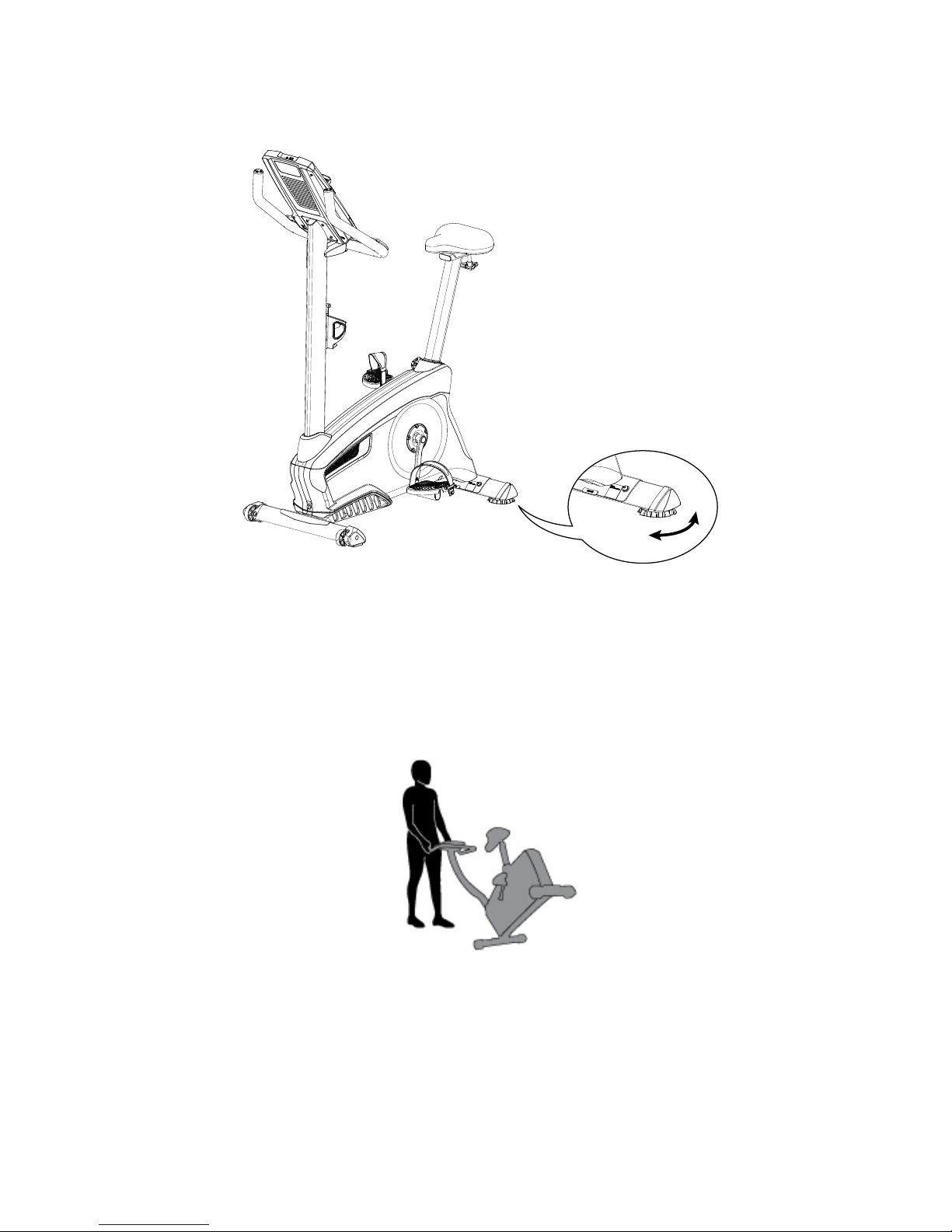
Leveling Your Bike
Levelers are found on each side of the Rear Stabilizer. Turn the stabilizer foot to adjust. Make sure the bike is level
and stable before you exercise.
Moving the Bike
To move the upright bike, carefully tilt the Handlebars toward you while pushing the front of the bike downward. Push the
bike to the desired location.
NOTICE: Be careful when you move the bike. Abrupt motions can affect the computer operation.
5
Page 6

Troubleshooting
Condition/Problem Things to Check Solution
No display/partial display/
unit will not turn on
Unit operates but Contact
HR not displayed
Unit operates but
Telemetric HR not
displayed (U626 only)
Unit operates but
Telemetric HR displayed
incorrectly (U626 only)
No speed/RPM reading,
Console displays “Please
Pedal” error code
Check electrical (wall)
outlet
Check connection on
console
Check data cable integrity All wires in cable should be intact. If any are visibly crimped or
Check data cable
connections/orientation
Check console display for
damage
Console Display If Console only has partial display and all connections are ne,
HR cable connection at
Console
Sensor grip Be sure hands are centered on HR sensors. Hands must be
Dry or calloused hands Sensors may have difculty with dried out or calloused hands.
Handlebar If tests reveal no other issues, Handlebars should be replaced.
Chest Strap (optional) Strap should be “POLAR®” compatible and uncoded. Make
Check User Prole Select the Edit User Prole option for the User Prole. Go to
Interference Try moving unit away from sources of interference (TV, Micro-
Replace Chest Strap If interference is eliminated and HR does not function, replace
Replace Console If HR still does not function, replace Console.
Interference Make sure that the HR receiver is not blocked by a personal
Check data cable integrity All wires in cable should be intact. If any are cut or crimped,
Check data cable
connections/orientation
Check magnet position
(requires shroud removal)
Check Speed Sensor
(requires shroud removal)
Make sure unit is plugged into a functioning wall outlet.
Connection should be secure and undamaged. Replace
adapter or connection at unit if either are damaged.
cut, replace cable.
Be sure cable is connected securely and oriented properly.
Small latch on connector should line up and snap into place.
Check for visual sign that console display is cracked or otherwise damaged. Replace Console if damaged.
replace the Console.
If the above steps do not resolve the problem, contact your
local distributor for further assistance.
Be sure cable is connected securely to Console.
kept still with relatively equal pressure applied to each side.
A conductive electrode cream (heart rate cream) can help
make better conduct. These are available on the web or at
medical or some larger tness stores.
sure strap is directly against skin and contact area is wet.
the WIRELESS HR setting and make sure that the current
value is set to ON.
wave, etc).
strap.
electronic device in the left side of the media tray.
replace cable.
Be sure cable is connected securely and oriented properly.
Small latch on connector should line up and snap into place.
Magnet should be in place on pulley.
Speed sensor should be aligned with magnet and connected to
data cable. Realign sensor if necessary. Replace if there is any
damage to the sensor or the connecting wire.
6
Page 7

Condition/Problem Things to Check Solution
Console shuts off (enters
sleep mode) while in use
Check electrical (wall)
outlet
Check connection on
console
Make sure unit is plugged into a functioning wall outlet.
Connection should be secure and undamaged. Replace
adapter or connection at unit if either are damaged.
Check data cable integrity All wires in the cable should be intact. If any are cut or crimped,
replace cable.
Check data cable
connections/orientation
Be sure cable is connected securely and oriented properly.
Small latch on connector should line up and snap into place.
Reset Machine Unplug unit from electrical outlet for 3 minutes. Reconnect to
outlet.
Check magnet position
Magnet should be in place on pulley.
(requires shroud removal)
Check Speed Sensor
(requires shroud removal)
Speed sensor should be aligned with magnet and connected to
data cable. Realign sensor if necessary. Replace if there is any
damage to the sensor or the connecting wire.
Unit rocks/does not sit
Check leveler adjustment Adjust levelers until bike is level.
level
Check surface under unit Adjustment may not be able to compensate for extremely un-
even surfaces. Move bike to level area.
Pedals loose/unit difcult
to pedal
Clicking sound when
pedaling
Check pedal to crank arm
connection
Check crank arm to axle
connection
Check pedal to crank arm
connection
Pedal should be tightened securely to crank. Insure connection
is not cross-threaded.
Crank should be tightened securely to axle. Be sure cranks are
connected at 180 degrees from each other.
Remove pedals. Make sure there is no debris on threads, and
reinstall the pedals.
Seat post movement Check locking pin Be sure adjustment pin is locked into one of the seat post
adjustment holes.
Check adjustment knob Be sure knob is securely tightened.
7
Page 8

Console Service Mode – x624 / x626 series (MY14) Consoles
The Console Setup Mode lets you input the date and time, set the units of measurement to either English or Metric, change
the machine type, control the sound settings ( on/ off), or see maintenance statistics (Total Run Hours – for service technician
use only).
1. Hold down the PAUSE/END button and Right button together for 3 seconds while in the Power-Up Mode to go into the
Console Setup Mode.
Note: Push PAUSE/END to exit the Console Setup Mode and return to the Power-Up Mode screen.
2. The Console display shows the Date prompt with the current setting. To change, push the Increase/Decrease buttons to
adjust the currently active value (flashing). Push the Left/Right buttons to change which segment is the currently active
value (month / day / year).
3. Push OK to set.
4. The Console display shows the Time prompt with the current setting. Push the Increase/Decrease buttons to adjust the
currently active value (flashing). Push the Left/Right buttons to change which segment is the currently active value (hour /
minute / AM or PM).
5. Push OK to set.
6. The Console display shows the Units prompt with the current setting. To change, push OK to start the Units option. Push
the Increase/Decrease buttons to change between “MILES” (Imperial English units) and “KM” (metric units).
Note: If the units change when there is data in User Statistics, the statistics convert to the new units.
7. Push OK to set.
8. The Console display shows the Machine Type prompt with the current setting. This menu option appears in the x624
series console only (not the x626 series consoles). Push the Increase/Decrease buttons to change between “BIKE” and
Elliptical (“ELIP”).
9. Push OK to set.
10. The Console display shows the Sound Settings prompt with the current setting. Push the Increase/Decrease buttons to
change between “ON” and “OFF”.
11. Push OK to set.
12. The Console display shows the TOTAL RUN HOURS for the machine.
To go to the next Console Setup Mode prompt, push the OK button.
To enter the Manufacturing Menu (MFG Menu), hold down the PAUSE/END button and Down button together for 3
seconds. The Console display shows the Firmware Version string. Push the Up/Down buttons to move through the MFG
Menu options. Push OK to make a selection.
a. ENTER MFG TEST – This option is intended for use on the manufacturing production line only. It is a chained series
of tests similar to the tests listed below, but optimized to be run on the production line. This chained test should not
be used anywhere but on the production line.
b. DEBUG TERMINAL – Not used.
c. MOVE LIFT – (E626 elliptical only) Used to adjust a new lift motor. The Console displays “UP MX DN MN RT CAL”: Up
arrow will move the lift motor to the maximum position; Down arrow will move the lift motor to the minimum position;
Right arrow will perform a lift motor calibration by moving the lift motor to its minimum and maximum position. Note:
Lift motor calibration is no longer required, so calibration is not needed.
d. RESET MFG NVM – Resets MFG NVM (non volatile memory). Must be run before lift motor calibration if a valid lift
table exists in NVM (lift motor has been calibrated before).
e. RUN BEEP TEST – Sounds each system beep / tone / sequence in order. Press any key to exit
f. RUN BUTTON TEST – The Console display shows the function of each button as buttons are pressed. If the display
shows an incorrect function, the overlay on the Console may be incorrect for that model. If the display does not show
a function, the firmware version may be incorrect. No beeps are sounded during this test.
To exit the test, push and hold one of the long key sequences (i.e. long Pause / End + Right or long Pause / End +
Down).
g. RUN LED TEST – Drives LEDs to the following states:
1. All LEDs On 1 second
8
Page 9

2. All LEDs Off 1 second
3. Sequence Segments 1 at a time – on 1 second, off 1 second
Press any key to exit test
h. RUN LCD TEST – Drives 3x5 and 1x5 LCD displays with the following patterns:
1. All segments on
2. All segments off
3. Set individual segments one at a time until all segments are illuminated.
Press any key to exit.
i. RESET CONSOLE – Resets the data from user inputs. The Console setup, user records and workout records will be
reset to defaults. This option does not reset MFG NVM (non volatile memory).
13. The Console display shows the Software Version prompt.
14. For the next prompt, push the OK button.
15 . The Console will display the Power-Up Mode screen.
9
Page 10
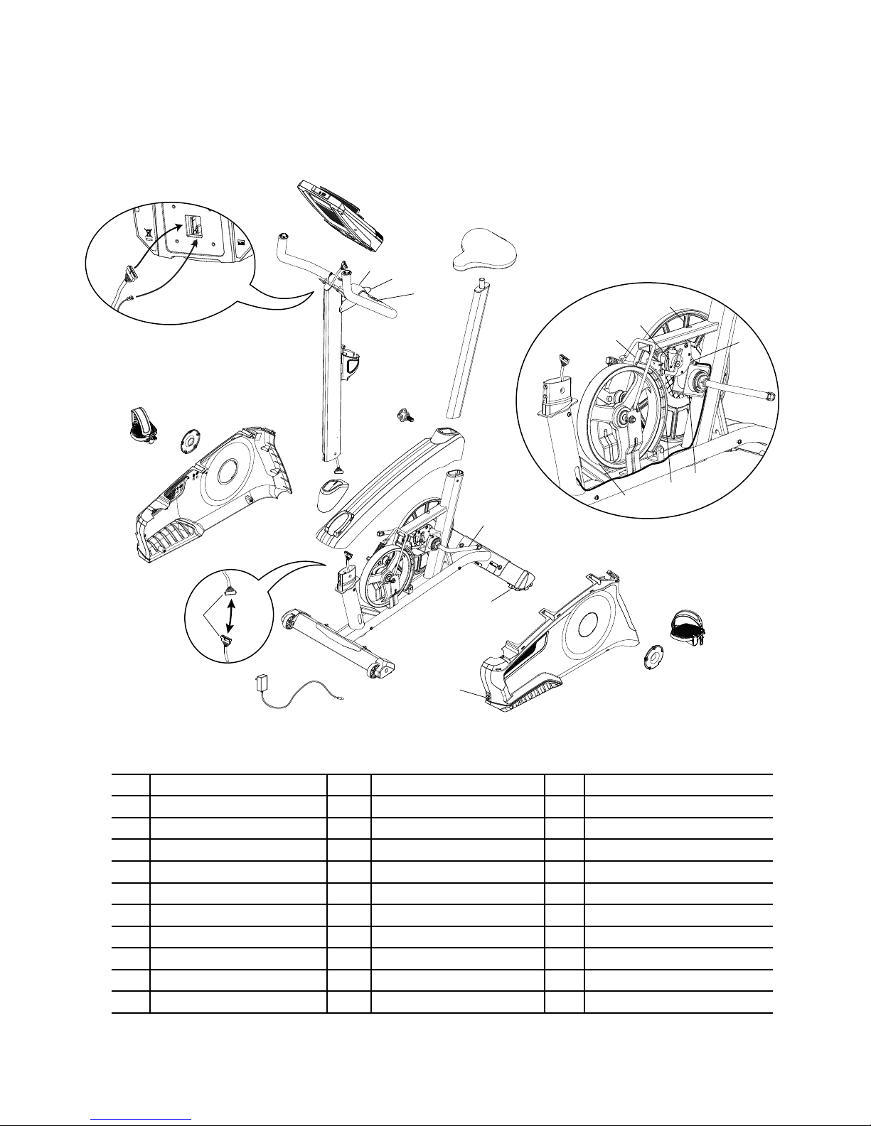
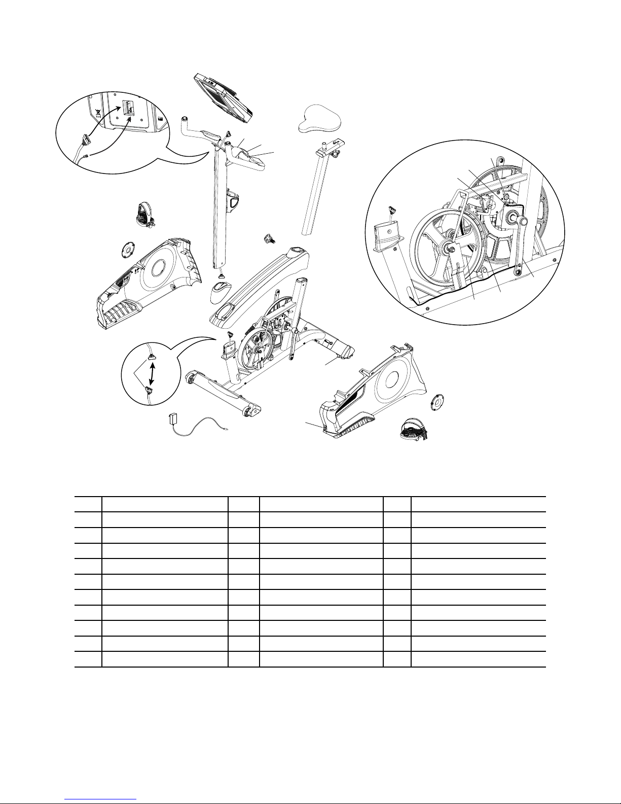
Maintenance Parts Exploded View
Your machine may differ. Use only as a guide.
U624
A
A
J
L
C
FF
G
J
K
DD
EE
M
R
B
I
U
P
H
N
O
BB
J
D
S
T
E
AA
W
CC
Y
D
Z
X
C
Q
V
F
FF
A Console L HR Cable W Flywheel
B Console Mast M CHR Sensors X Brake Assembly
C Pedals N Seat Y RPM Sensor
D Crank Arms O Seat Post w/ Slider Z Speed Sensor Magnet
E Left Shroud P Adjustment Knob AA Servo Motor
F Power Inlet Q AC Adapter BB Drive Belt
G Right Shroud R Water Bottle Holder CC Drive Pulley
H Top Shroud S Rear Stabilizer DD Handlebar Mount Cover
I Mast Gasket T Levelers EE T-handle
J Data Cable U Front Stabilizer FF Cover, Crank Disc
K Handlebars V Transport Wheels
10
Page 11
U626
A
A
J
L
C
FF
G
J
K
DD
EE
M
R
B
I
U
P
H
D
N
Z
Y
O
J
S
T
E
AA
W
CC
D
X
BB
FF
Q
V
F
C
A Console L HR Cable W Flywheel
B Console Mast M CHR Sensors X Brake Assembly
C Pedals N Seat Y RPM Sensor
D Crank Arms O Seat Post w/ Slider Z Speed Sensor Magnet
E Left Shroud P Adjustment Knob AA Servo Motor
F Power Inlet Q AC Adapter BB Drive Belt
G Right Shroud R Water Bottle Holder CC Drive Pulley
H Top Shroud S Rear Stabilizer DD Handlebar Mount Cover
I Mast Gasket T Levelers EE T-handle
J Data Cable U Front Stabilizer FF Cover, Crank Disc
K Handlebars V Transport Wheels
11
Page 12

REPLACEMENT PROCEDURE SKILL LEVEL
WARNING
DANGER
Level I : Low - very little mechanical knowledge or exposure.
Level II : Intermediate - some experience with mechanical procedures
Level III : Advanced - knowledgeable about mechanical procedures
To reduce the risk of electrical shock or unsupervised usage of the equipment, always unplug the power
cord from the wall outlet and wait 5 minutes before cleaning, maintaining or repairing this machine. Place
the power cord in a secure location.
When disposing of old parts, obey the applicable local and provincial requirements.
!
For instructions to replace the following parts, please refer to the Assembly Manual for your bike:
• AC Adapter
• Seat
• Seat Post
• Front Stabilizer
• Rear Stabilizer
• Water Bottle Holder
12
Page 13
Adjust the Belt Tension on the Nautilus® U624/U626 and
WARNING
DANGER
R624/R626 (Model Year 2014) Bikes
NOTICE: This document provides instructions for the adjustment of the Drive Belt tension on the Nautilus® U624 and U626 Upright Bikes, and
R624 and R626 Recumbent Bikes.
If you need assistance, please contact your local distributor. To find your local distributor, go to: www.nautilusinternational.com
This icon means a potentially hazardous situation which, if not avoided, could result in death or serious injury. Read and understand all Warnings
on this machine.
Nautilus, Inc., , www.NautilusInc.com - Customer Service: technics@nautilus.com | © 2014 Nautilus, Inc. | ® indicates trademarks registered in the United States. These marks may be registered in other nations or otherwise
protected by common law. | ORIGINAL DOCUMENT - ENGLISH VERSION ONLY
Replacement Procedure
Skill Level: II
8008330.040115.A
Important Safety Instructions - Before servicing or using this equipment, obey the following warnings:
This icon means a potentially hazardous situation which, if not avoided, could result in death or serious injury. Read and understand all Warnings on
this machine.
To reduce the risk of electrical shock or unsupervised usage of the equipment, always unplug the power cord from the wall outlet and
wait 5 minutes before cleaning, maintaining or repairing this machine. Place the power cord in a secure location.
• Read and understand the Part Replacement Procedure before working on the machine. Failure to obey the instructions and safety warnings
could cause injury to the service technician or bystanders.
• Keep bystanders and children away from the product being serviced at all times.
• Make sure that the repair is done in an appropriate work space away from foot trafc and exposure to bystanders.
• Some components of the equipment can be heavy or awkward. Enlist the service of a second person when you do maintenance steps
involving these components. Do not try to do heavy or awkward steps on your own.
• If replacement parts are necessary, use only genuine Nautilus replacement parts and hardware. Failure to use genuine replacement parts
can cause a risk to users, keep the machine from operating correctly and void the warranty.
• Be sure that all warning stickers and instructional placards applied to the product stay present and in good condition when doing
maintenance or replacing components. If necessary request replacement warning stickers or placards from from your local distributor.
• Do not try to change the design or functionality of the machine being serviced as this can adversely affect user safety.
• Do not use the machine until all shrouds, instructions, warning labels and correct functionality have been verified and tested for correct
performance.
• This product contains magnets. Magnetic elds can interfere with the normal use of certain medical devices at a close range. Users may
come into proximity of the magnets in the assembly, maintenance, and/or use of the product. Given the obvious importance of these devices,
such as a pacemaker, it is important that you consult with your medical provider in connection with the use of this equipment. Please consult
the “Safety Warning Labels and Serial Number” section in the Owner’s Manual to determine the location of the magnets on this product.
Tools Required (not included)
#2 Phillips screwdriver 15mm open end wrench
Small athead screwdriver 15mm socket and wrench
Pedal wrench (U624/R624)
or crank puller (U626/R626)
13
Page 14

NOTICE: It is necessary to remove the Shrouds for this procedure. Refer to the “Replace the Shrouds” procedure.
To reduce the risk of electrical shock or unsupervised usage of the equipment, always unplug the power cord from the wall outlet and wait 5
!
minutes before cleaning, maintaining or repairing this machine. Place the power cord in a secure location.
Note: Your machine may not match the image. For reference only.
1. Remove the Top Shroud, Left Shroud and Right Shroud from the
Main Unit. Refer to the “Replace the Shrouds” procedure.
2. To test the Drive Belt tension:
• Push the Drive Belt downward at the midpoint (M) between the
pulleys and measure the distance. The Drive Belt should have
only 0.25” (0.64 cm) of give. See Figure 1.
Or:
• Hold the edges of the Drive Belt at the midpoint (M) and twist it
(see Figure 2). It should turn only 90 degrees
(1/4 turn, to vertical).
If the tension is correct, go to Step 6.
If the tension is too loose or too tight, adjust the position of the
Flywheel. Continue to Step 3.
3. To loosen the Flywheel hardware (A), use a 15 mm open end
wrench to hold the nut on one side steady and loosen the nut on the
opposite side with a 15 mm socket and wrench.
Figure 1
0.64 cm
0.25”
}
M
A
4. Move the Flywheel in the Main Frame bracket as necessary to
adjust the tension. Hold it in position and tighten the hardware.
Note: This step may require two people.
To tighten the Flywheel hardware, use a 15 mm open end
wrench to hold the nut on one side steady and tighten the nut on
the opposite side with a 15 mm socket and wrench.
5. Carefully turn the crank arms and check the movement of the drive
belt. The Crank Arms and Flywheel should move as one.
Be sure to keep ngers clear of all pinch hazards when you turn
!
the Drive Pulley.
Adjust the belt tension again if necessary.
M
(Main Frame bracket not shown for clarity)
Figure 2
14
Page 15

6. Reassembly is the reverse procedure.
NOTICE: Be sure not to crimp any cables.
U624/R624 bikes—To reinstall the Pedals, carefully align the threads
and hand tighten to prevent cross-threading. Then tighten fully with pedal
wrench.
Note: The Left Pedal is reverse-threaded. Orientation is based
from a seated position on the bike. The Left Pedal has an “L”,
the Right Pedal an “R”.
16. Final Inspection
Inspect your machine to ensure that all hardware is tight and components
are properly assembled.
Do not use until the machine has been fully assembled and
!
inspected for correct performance in accordance with the Owner’s
Manual.
15
Page 16
Set the Brake Tension (Calibration)
WARNING
DANGER
®
on the Nautilus
NOTICE: This document provides instructions for the calibration of the Brake tension on the Nautilus® U624 and U626 Upright Bikes.
If you need assistance, please contact your local distributor. To find your local distributor, go to: www.nautilusinternational.com
U624/U626 (Model Year 2014) Bikes
Replacement Procedure
Skill Level: III
8008331.040115.A
This icon means a potentially hazardous situation which, if not avoided, could result in death or serious injury. Read and understand all Warnings
on this machine.
Nautilus, Inc., , www.NautilusInc.com - Customer Service: technics@nautilus.com | © 2014 Nautilus, Inc. | ® indicates trademarks registered in the United States. These marks may be registered in other nations or
otherwise protected by common law. | ORIGINAL DOCUMENT - ENGLISH VERSION ONLY
Important Safety Instructions - Before servicing or using this equipment, obey the following warnings:
This icon means a potentially hazardous situation which, if not avoided, could result in death or serious injury. Read and understand all Warnings on
this machine.
To reduce the risk of electrical shock or unsupervised usage of the equipment, always unplug the power cord from the wall outlet and
wait 5 minutes before cleaning, maintaining or repairing this machine. Place the power cord in a secure location.
• Read and understand the Part Replacement Procedure before working on the machine. Failure to obey the instructions and safety warnings could cause
injury to the service technician or bystanders.
• Keep bystanders and children away from the product being serviced at all times.
• Make sure that the repair is done in an appropriate work space away from foot trafc and exposure to bystanders.
• Some components of the equipment can be heavy or awkward. Enlist the service of a second person when you do maintenance steps involving these
components. Do not try to do heavy or awkward steps on your own.
• If replacement parts are necessary, use only genuine replacement parts and hardware supplied by Nautilus. Failure to use genuine replacement parts can
cause a risk to users, keep the machine from operating correctly and void the warranty.
• Be sure that all warning stickers and instructional placards applied to the product stay present and in good condition when doing maintenance or replacing
components. If necessary request replacement warning stickers or placards from from your local distributor.
• Do not try to change the design or functionality of the machine being serviced as this can adversely affect user safety.
• Do not use the machine until all shrouds, instructions, warning labels and correct functionality have been verified and tested for correct performance.
• This product contains magnets. Magnetic elds can interfere with the normal use of certain medical devices at a close range. Users may come into
proximity of the magnets in the assembly, maintenance, and/or use of the product. Given the obvious importance of these devices, such as a pacemaker, it
is important that you consult with your medical provider in connection with the use of this equipment. Please consult the “Safety Warning Labels and Serial
Number” section in the Owner’s Manual to determine the location of the magnets on this product.
Tools Required (not included)
#2 Phillips screwdriver 7mm open end wrench
Small athead screwdriver
Pedal wrench (U624)
or crank puller (U626)
2.5” x 10” cardboard (3mm / 1/8” thick)
and tape
16
Page 17
NOTICE: It is necessary to remove the shrouds for this procedure. Refer to the “Replace the Shrouds” procedure.
Note: Your machine may not match the image. For reference only.
1. Disconnect and reconnect the AC Adapter from the wall outlet to turn
the power off and on.
2. Push QuickStart and verify that the console shows that the default
resistance level is 4.
Disconnect all power and allow to sit for 5 minutes.
3. Carefully remove the Seat Post, Left Shroud and Right Shroud.
(Refer to the “Replace the Shrouds” procedure.) Do not remove the
Console and Mast, and keep the Power Inlet cable (P) in the Shroud
connected to the wiring harness on the motor (D). Slide the Mast Gasket
and Top Shroud up the Mast. Lean the Top Shroud against the Seat Post
mount to keep it clear of the pulley assembly.
Note: It may be necessary to remove the Water Bottle Holder.
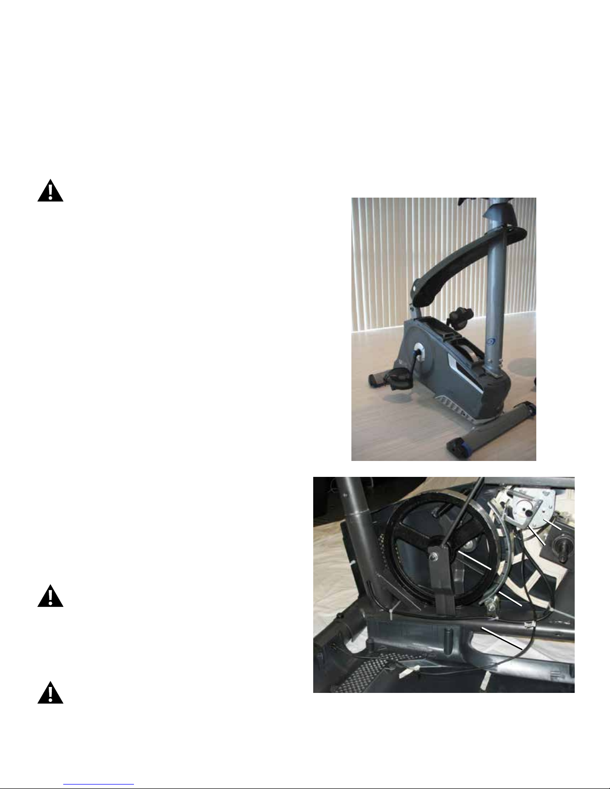
4. Insert 2.5” x 10” cardboard between the Brake Magnet (A) and the
Flywheel (B), and tape the cardboard to the Brake Magnet.
Note: Be sure the cardboard covers all of the Brake Magnet.
5. Turn the power on again.
Machine is on. Current is active. There is risk of electrical shock.
6. Use the console to set the resistance to the highest level. This moves
the Brake Magnet Arm (A1) forward. After the Brake Magnet Arm stops at
the highest resistance level, turn power off.
Disconnect all power and allow to sit for 5 minutes.
D
B
A1
A
P
17
Page 18
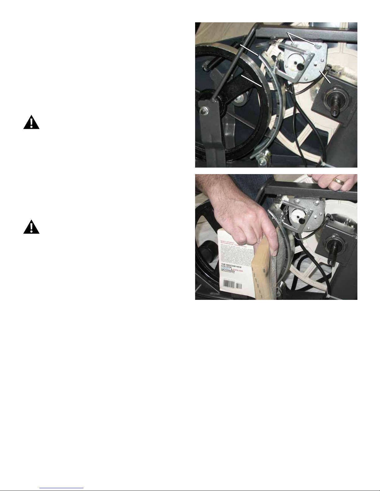
7. To adjust the Brake tension, loosen the 2 hex head bolts (C) and
move the Servo Motor assembly (D) until the closest point on the Brake
Magnet (A) is within 3.0 mm (1/8”) of the Flywheel (B). Tighten the bolts.
Note: If the cardboard is not 3mm (1/8”) thick, you can use
the pages of a paperback book to measure the gap.
Approximately 36 pages (sheets) = 3mm.
8. Turn the power on again. Use the console to check the resistance
adjustment.
Machine is on. Current is active. There is risk of electrical shock.
Note: Before fully attaching the Shrouds, remove the cardboard
from between the Brake Magnet (A) and the Flywheel (B).
Power up the machine to verify that the Magnet Arm can
move freely, and that the Brake Magnet and Flywheel do not
touch.
9. Final Inspection
Inspect your machine to ensure that all hardware is tight and components
are properly assembled.
C
A
B
D
Do not use until the machine has been fully assembled and
inspected for correct performance in accordance with the
Owner’s Manual.
18
Page 19

Replace the Console on the Nautilus®
WARNING
DANGER
U624/U626 and R624/R626 (Model Year 2014) Bikes
NOTICE: This document provides instructions for the replacement of the Console on the Nautilus® U624 and U626 Upright Bikes, and R624 and R626 Recumbent Bikes.
If you need assistance, please contact your local distributor. To find your local distributor, go to: www.nautilusinternational.com
This icon means a potentially hazardous situation which, if not avoided, could result in death or serious injury. Read and understand all Warnings
on this machine.
Nautilus, Inc., , www.NautilusInc.com - Customer Service: technics@nautilus.com | © 2014 Nautilus, Inc. | ® indicates trademarks registered in the United States. These marks may be registered in other nations or otherwise
protected by common law. | ORIGINAL DOCUMENT - ENGLISH VERSION ONLY
Replacement Procedure
Skill Level: I
8008332.040115.A
Important Safety Instructions - Before servicing or using this equipment, obey the following warnings:
This icon means a potentially hazardous situation which, if not avoided, could result in death or serious injury. Read and understand all Warnings on
this machine.
To reduce the risk of electrical shock or unsupervised usage of the equipment, always unplug the power cord from the wall outlet and
wait 5 minutes before cleaning, maintaining or repairing this machine. Place the power cord in a secure location.
• Read and understand the Part Replacement Procedure before working on the machine. Failure to obey the instructions and safety warnings
could cause injury to the service technician or bystanders.
• Keep bystanders and children away from the product being serviced at all times.
• Make sure that the repair is done in an appropriate work space away from foot trafc and exposure to bystanders.
• Some components of the equipment can be heavy or awkward. Enlist the service of a second person when you do maintenance steps
involving these components. Do not try to do heavy or awkward steps on your own.
• If replacement parts are necessary, use only genuine Nautilus replacement parts and hardware. Failure to use genuine replacement parts
can cause a risk to users, keep the machine from operating correctly and void the warranty.
• Be sure that all warning stickers and instructional placards applied to the product stay present and in good condition when doing
maintenance or replacing components. If necessary request replacement warning stickers or placards from from your local distributor.
• Do not try to change the design or functionality of the machine being serviced as this can adversely affect user safety.
• Do not use the machine until all shrouds, instructions, warning labels and correct functionality have been verified and tested for correct
performance.
• This product contains magnets. Magnetic elds can interfere with the normal use of certain medical devices at a close range. Users may
come into proximity of the magnets in the assembly, maintenance, and/or use of the product. Given the obvious importance of these devices,
such as a pacemaker, it is important that you consult with your medical provider in connection with the use of this equipment. Please consult
the “Safety Warning Labels and Serial Number” section in the Owner’s Manual to determine the location of the magnets on this product..
Tools Required (not included)
#2 Phillips screwdriver
19
Page 20

To reduce the risk of electrical shock or unsupervised usage of the equipment, always unplug the power cord from the wall outlet and the
machine and wait 5 minutes before cleaning, maintaining or repairing the machine. Place the power cord in a secure location.
Note: Your machine may not match the image. For reference only.
1. Remove screws that attach Console to the Mast. Carefully lift the
Console off the Mast.
2. Disconnect the Data Cable and Heart Rate Cable from the back of
the Console. Discard the Console and screws.
Note: Do not let the cables fall down inside the Mast. This step may
require two people.
3. Installation is the reverse procedure.
4. Inspect your machine to ensure that all hardware is tight and compo-
nents are properly assembled.
Do not use until the machine has been fully assembled and
inspected for correct performance in accordance with the Owner’s
Manual.
Initial Setup
During the rst power-up, the Console should be set up with the date,
time, your preferred measurement units and machine type.
1. Date: Push the Increase/Decrease buttons to adjust the currently active
value (ashing). Push the Left/Right buttons to change which segment is
the currently active value (month / day / year).
2. Push OK to set.
3. Time: Push the Increase/Decrease buttons to adjust the currently active
value (ashing). Push the Left/Right buttons to change which segment is
the currently active value (hour / minute / AM or PM).
4. Push OK to set.
5. Units of Measurement: Push the Increase/Decrease buttons to adjust
between “MILES” (Imperial English) or “KM” (metric).
6. Push OK to set.
7. The Console display shows the Machine Type prompt with the current
setting. This menu option appears in the x624 series console only (not the
x626 series consoles). Push the Increase/Decrease buttons to change
between “BIKE” and Elliptical (“ELIP”).
8. Push OK to set. The Console goes back to the Power-Up / Idle Mode
screen.
Note: To adjust these selections, consult the “Console Service
Mode” section.
20
Page 21

Replace the Pedals on the Nautilus®
WARNING
DANGER
U624/U626 and R624/R626 (Model Year 2014) Bikes
NOTICE: This document provides instructions for the replacement of the Pedals on the Nautilus® U624 and U626 Upright Bikes, and R624 and R626
Recumbent Bikes.
If you need assistance, please contact your local distributor. To find your local distributor, go to: www.nautilusinternational.com
This icon means a potentially hazardous situation which, if not avoided, could result in death or serious injury. Read and understand all Warnings
on this machine.
Nautilus, Inc., , www.NautilusInc.com - Customer Service: technics@nautilus.com | © 2014 Nautilus, Inc. | ® indicates trademarks registered in the United States. These marks may be registered in other nations or otherwise
protected by common law. | ORIGINAL DOCUMENT - ENGLISH VERSION ONLY
Replacement Procedure
Skill Level: I
8008333.040115.A
Important Safety Instructions - Before servicing or using this equipment, obey the following warnings:
This icon means a potentially hazardous situation which, if not avoided, could result in death or serious injury. Read and understand all Warnings on
this machine.
To reduce the risk of electrical shock or unsupervised usage of the equipment, always unplug the power cord from the wall outlet and
wait 5 minutes before cleaning, maintaining or repairing this machine. Place the power cord in a secure location.
• Read and understand the Part Replacement Procedure before working on the machine. Failure to obey the instructions and safety warnings
could cause injury to the service technician or bystanders.
• Keep bystanders and children away from the product being serviced at all times.
• Make sure that the repair is done in an appropriate work space away from foot trafc and exposure to bystanders.
• Some components of the equipment can be heavy or awkward. Enlist the service of a second person when you do maintenance steps
involving these components. Do not try to do heavy or awkward steps on your own.
• If replacement parts are necessary, use only genuine replacement parts and hardware supplied by Nautilus. Failure to use genuine replacement parts can cause a risk to users, keep the machine from operating correctly and void the warranty.
• Be sure that all warning stickers and instructional placards applied to the product stay present and in good condition when doing
maintenance or replacing components. If necessary request replacement warning stickers or placards from from your local distributor.
• Do not try to change the design or functionality of the machine being serviced as this can adversely affect user safety.
• Do not use the machine until all shrouds, instructions, warning labels and correct functionality have been verified and tested for correct
performance.
• This product contains magnets. Magnetic elds can interfere with the normal use of certain medical devices at a close range. Users may
come into proximity of the magnets in the assembly, maintenance, and/or use of the product. Given the obvious importance of these devices,
such as a pacemaker, it is important that you consult with your medical provider in connection with the use of this equipment. Please consult
the “Safety Warning Labels and Serial Number” section in the Owner’s Manual to determine the location of the magnets on this product.
Tools Required (not included)
Pedal wrench
21
Page 22

Note: Your machine may not match the image. For reference only.
1. Loosen and remove the old Pedals. Discard the old Pedals.
Note: The Left Pedal is reverse-threaded. Orientation is based
from a seated position on the bike. The Left Pedal has an “L”,
the Right Pedal an “R”.
(R)
(L)
2. Install the new Pedals. Carefully align the threads and hand tighten
to prevent cross-threading. Then tighten fully with pedal wrench.
Note: The Left Pedal is reverse-threaded. Be sure to attach
Pedals on the correct side of the Bike. Orientation is based
from a seated position on the bike. The Left Pedal has an “L”,
the Right Pedal an “R”.
(R)
3. Final Inspection
Inspect your machine to ensure that all hardware is tight and components
are properly assembled.
(L)
Do not use until the machine has been fully assembled and
inspected for correct performance in accordance with the
Owner’s Manual.
22
Page 23

Replace the Crank Arms
WARNING
DANGER
®
on the Nautilus
NOTICE: This document provides instructions for the replacement of the Crank Arms on the Nautilus® U626 Upright Bike and R626 Recumbent Bike.
If you need assistance, please contact your local distributor. To find your local distributor, go to: www.nautilusinternational.com
This icon means a potentially hazardous situation which, if not avoided, could result in death or serious injury. Read and understand all Warnings
on this machine.
Nautilus, Inc., , www.NautilusInc.com - Customer Service: technics@nautilus.com | © 2014 Nautilus, Inc. | ® indicates trademarks registered in the United States. These marks may be registered in other nations or otherwise
protected by common law. | ORIGINAL DOCUMENT - ENGLISH VERSION ONLY
U626/R626 (Model Year 2014) Bikes
Replacement Procedure
Skill Level: II
8008334.040115.A
Important Safety Instructions - Before servicing or using this equipment, obey the following warnings:
This icon means a potentially hazardous situation which, if not avoided, could result in death or serious injury. Read and understand all Warnings on
this machine.
To reduce the risk of electrical shock or unsupervised usage of the equipment, always unplug the power cord from the wall outlet and
wait 5 minutes before cleaning, maintaining or repairing this machine. Place the power cord in a secure location.
• Read and understand the Part Replacement Procedure before working on the machine. Failure to obey the instructions and safety warnings
could cause injury to the service technician or bystanders.
• Keep bystanders and children away from the product being serviced at all times.
• Make sure that the repair is done in an appropriate work space away from foot trafc and exposure to bystanders.
• Some components of the equipment can be heavy or awkward. Enlist the service of a second person when you do maintenance steps
involving these components. Do not try to do heavy or awkward steps on your own.
• If replacement parts are necessary, use only genuine replacement parts and hardware supplied by Nautilus. Failure to use genuine replacement parts can cause a risk to users, keep the machine from operating correctly and void the warranty.
• Be sure that all warning stickers and instructional placards applied to the product stay present and in good condition when doing
maintenance or replacing components. If necessary request replacement warning stickers or placards from from your local distributor.
• Do not try to change the design or functionality of the machine being serviced as this can adversely affect user safety.
• Do not use the machine until all shrouds, instructions, warning labels and correct functionality have been verified and tested for correct
performance.
• This product contains magnets. Magnetic elds can interfere with the normal use of certain medical devices at a close range. Users may
come into proximity of the magnets in the assembly, maintenance, and/or use of the product. Given the obvious importance of these devices,
such as a pacemaker, it is important that you consult with your medical provider in connection with the use of this equipment. Please consult
the “Safety Warning Labels and Serial Number” section in the Owner’s Manual to determine the location of the magnets on this product.
Tools Required (not included)
#2 Phillips screwdriver 13mm wrench and socket
Flathead screwdriver Crank puller
Adjustable wrench
Pedal wrench
23
Page 24

Note: Your machine may not match the image. For reference only.
1. Loosen and remove the old Pedals. Set them safely aside for
reassembly.
Note: The Left Pedal is reverse-threaded. Orientation is based
from a seated position on the bike. The Left Pedal has an “L”,
the Right Pedal an “R”.
(R)
(L)
2. Using a athead screwdriver, remove the threaded Cap (A) from the
Crank Arm (B) to expose the Hex Head Bolt (C).
Crank arm shown is on a Schwinn® 170 bike.
3. Using a wrench and socket, remove the Hex Head Bolt (C).
A
B
B
C
24
Page 25

4. Thread the Crank Puller into the Crank Arm (B). When the Crank
Puller is in the correct position, only 1-2 threads on the outer portion (CP2)
of the Crank Puller should show.
Note: Be sure the end of the Bolt (CP1) of the Crank Puller is ush
with the Nut (CP2) as shown, before use.
5. Using a wrench, turn the inner portion (CP3) of the Crank Puller
clockwise. The Crank Arm (B) will slide off as it is tightened.
CP1 CP2 CP3
CP2
B
CP3
25
Page 26

6. Installation is the reverse procedure. Installation does not require the
use of the crank puller. Be sure the Crank Arms are connected at 180°
from each other.
To reinstall the Pedals, carefully align the threads and hand tighten to
prevent cross-threading. Then tighten fully with pedal wrench.
Note: The Left Pedal is reverse-threaded. Be sure to attach
Pedals on the correct side of the Bike. Orientation is based
from a seated position on the bike. The Left Pedal has an “L”,
the Right Pedal an “R”.
(R)
7. Final Inspection
Inspect your machine to ensure that all hardware is tight and components
are properly assembled.
Do not use until the machine has been fully assembled and
inspected for correct performance in accordance with the
Owner’s Manual.
(L)
26
Page 27

Replace the Transport Wheels, Endcaps and Footpads on the
WARNING
DANGER
®
Nautilus
NOTICE: This document provides instructions for the replacement of the Transport Wheels, Front Endcaps and Footpads on the Nautilus® U624
and U626 Upright Bikes, R624 and R626 Recumbent Bikes, and E624 and E626 Elliptical Fitness Machines.
If you need assistance, please contact your local distributor. To find your local distributor, go to: www.nautilusinternational.com
This icon means a potentially hazardous situation which, if not avoided, could result in death or serious injury. Read and understand all Warnings
on this machine.
Nautilus, Inc., , www.NautilusInc.com - Customer Service: technics@nautilus.com | © 2014 Nautilus, Inc. | ® indicates trademarks registered in the United States. These marks may be registered in other nations or
otherwise protected by common law. | ORIGINAL DOCUMENT - ENGLISH VERSION ONLY
U/R/E 624/626 (Model Year 2014) Bikes and Elllipticals
Replacement Procedure
Skill Level: II
8008335.040115.A
Important Safety Instructions - Before servicing or using this equipment, obey the following warnings:
This icon means a potentially hazardous situation which, if not avoided, could result in death or serious injury. Read and understand all Warnings on
this machine.
To reduce the risk of electrical shock or unsupervised usage of the equipment, always unplug the power cord from the wall outlet and
wait 5 minutes before cleaning, maintaining or repairing this machine. Place the power cord in a secure location.
• Read and understand the Part Replacement Procedure before working on the machine. Failure to obey the instructions and safety warnings
could cause injury to the service technician or bystanders.
• Keep bystanders and children away from the product being serviced at all times.
• Make sure that the repair is done in an appropriate work space away from foot trafc and exposure to bystanders.
• Some components of the equipment can be heavy or awkward. Enlist the service of a second person when you do maintenance steps
involving these components. Do not try to do heavy or awkward steps on your own.
• If replacement parts are necessary, use only genuine replacement parts and hardware supplied by Nautilus. Failure to use genuine replacement parts can cause a risk to users, keep the machine from operating correctly and void the warranty.
• Be sure that all warning stickers and instructional placards applied to the product stay present and in good condition when doing
maintenance or replacing components. If necessary request replacement warning stickers or placards from from your local distributor.
• Do not try to change the design or functionality of the machine being serviced as this can adversely affect user safety.
• Do not use the machine until all shrouds, instructions, warning labels and correct functionality have been verified and tested for correct
performance.
• This product contains magnets. Magnetic elds can interfere with the normal use of certain medical devices at a close range. Users may
come into proximity of the magnets in the assembly, maintenance, and/or use of the product. Given the obvious importance of these devices,
such as a pacemaker, it is important that you consult with your medical provider in connection with the use of this equipment. Please consult
the “Safety Warning Labels and Serial Number” section in the Owner’s Manual to determine the location of the magnets on this product.
Tools Required (not included)
6mm hex key Static solid object (like a book or box)
#2 Phillips screwdriver (short)
13mm open end wrench
27
Page 28

Note: Your machine may not match the image. For reference only.
1. Place a static object (like a book or box) under the front stabilizer (C).
The static object should not be compressible.
D
2. Using a short #2 Phillips screwdriver, loosen and remove the screws
(A1) from the Footpad (A), and set them safely aside. Remove the
Footpad from the front stabilizer (D). Set the Footpad and screws safely
aside.
3. Loosen and remove the screw (B1) from the Endcap assembly (B)
and set it safely aside. Remove the Endcap from the front stabilizer (D).
Set the Endcap and screw safely aside.
A
A1
D
B1
B
4. Using the 6mm hex key and 13mm wrench, loosen and remove
the hardware (C1) from the old Transport Wheel assembly (C). Remove
the old Transport Wheel from the front stabilizer bracket (D1). Set the
Transport Wheel and hardware safely aside.
5. Installation is the reverse procedure.
NOTICE: Before fully attaching the Endcap, be sure that the Trans-
port Wheel can turn freely.
6. Dispose of the old parts.
7. Final Inspection
Inspect your machine to ensure that all hardware is tight and components
are properly assembled.
Do not use until the machine has been fully assembled and
inspected for correct performance in accordance with the
Owner’s Manual.
C1
D1
C
28
Page 29

Replace the Shrouds
WARNING
DANGER
®
on the Nautilus
NOTICE: This document provides instructions for the replacement of the Shrouds on the Nautilus® U624 and U626 Upright Bikes.
If you need assistance, please contact your local distributor. To find your local distributor, go to: www.nautilusinternational.com
This icon means a potentially hazardous situation which, if not avoided, could result in death or serious injury. Read and understand all Warnings
on this machine.
Nautilus, Inc., , www.NautilusInc.com - Customer Service: technics@nautilus.com | © 2014 Nautilus, Inc. | ® indicates trademarks registered in the United States. These marks may be registered in other nations or
otherwise protected by common law. | ORIGINAL DOCUMENT - ENGLISH VERSION ONLY
U624/U626 (Model Year 2014) Bikes
Replacement Procedure
Skill Level: II
8008336.040115.A
Important Safety Instructions - Before servicing or using this equipment, obey the following warnings:
This icon means a potentially hazardous situation which, if not avoided, could result in death or serious injury. Read and understand all Warnings on
this machine.
To reduce the risk of electrical shock or unsupervised usage of the equipment, always unplug the power cord from the wall outlet and
wait 5 minutes before cleaning, maintaining or repairing this machine. Place the power cord in a secure location.
• Read and understand the Part Replacement Procedure before working on the machine. Failure to obey the instructions and safety warnings
could cause injury to the service technician or bystanders.
• Keep bystanders and children away from the product being serviced at all times.
• Make sure that the repair is done in an appropriate work space away from foot trafc and exposure to bystanders.
• Some components of the equipment can be heavy or awkward. Enlist the service of a second person when you do maintenance steps
involving these components. Do not try to do heavy or awkward steps on your own.
• If replacement parts are necessary, use only genuine replacement parts and hardware supplied by Nautilus. Failure to use genuine replacement parts can cause a risk to users, keep the machine from operating correctly and void the warranty.
• Be sure that all warning stickers and instructional placards applied to the product stay present and in good condition when doing
maintenance or replacing components. If necessary request replacement warning stickers or placards from from your local distributor.
• Do not try to change the design or functionality of the machine being serviced as this can adversely affect user safety.
• Do not use the machine until all shrouds, instructions, warning labels and correct functionality have been verified and tested for correct
performance.
• This product contains magnets. Magnetic elds can interfere with the normal use of certain medical devices at a close range. Users may
come into proximity of the magnets in the assembly, maintenance, and/or use of the product. Given the obvious importance of these devices,
such as a pacemaker, it is important that you consult with your medical provider in connection with the use of this equipment. Please consult
the “Safety Warning Labels and Serial Number” section in the Owner’s Manual to determine the location of the magnets on this product.
Tools Required (not included)
#2 Phillips screwdriver 6mm hex key
Flathead screwdriver 13mm wrench and socket (U626)
Pedal wrench (U624)
or crank puller (U626)
29
Page 30

To reduce the risk of electrical shock or unsupervised usage of the equipment, always unplug the power cord from the wall outlet and wait 5
minutes before cleaning, maintaining or repairing this machine. Place the power cord in a secure location.
Note: Your machine may not match the image. For reference only.
1. Remove the Seat Post and the Seat Adjustment Knob (A). Set them safely
aside for reassembly.
A
2. Your machine has one of these Crank congurations. Please use the im-
ages to select your conguration:
1-Piece Crank:
Go to Step 6.
3. Using a wrench and socket, remove the Hex Head Bolt (D) .
4. Thread the Crank Puller into the Crank Arm (C). When the Crank Puller is
in the correct position, only 1-2 threads on the outer portion (CP2) of the Crank
Puller should show.
Note: Be sure the end of the Bolt (CP1) of the Crank Puller is ush with
the Nut (CP2) as shown, before use.
5. Using a wrench, turn the inner portion (CP3) of the Crank Puller clockwise.
The Crank Arm (C) will slide off as it is tightened.
Go to Step 8.
B
C
3-Piece Crank:
Using a athead screwdriver, remove the threaded Cap (B)
from the Crank Arm (C) to expose the Hex Head Bolt (D).
Continue to Step 3.
D
C
CP1 CP2 CP3
30
Page 31

6. Loosen and remove the Pedals. Set them safely aside for
reassembly.
Note: The Left Pedal is reverse-threaded.
Orientation is based from a seated position on the bike. The
Left Pedal has an “L”, the Right Pedal an “R”.
(R)
7. Twist the Crank Cover (P) toward the front of the machine to
disengage the inner tabs. Carefully remove the Crank Covers and set
them safely aside.
P
(L)
8. Slide the Mast Gasket up the Mast.
9. Remove the hardware (indicated) from the Mast. Gently pull the Mast
out and disconnect the cables. Set the hardware, Mast and Mast Gasket
safely aside.
NOTICE: Do not crimp the cables. This step may require two people.
Note: Do not let the cable fall down inside the Frame.
10. Bend the edges of the Top Shroud to disengage the inside tabs from
the Main Assembly, and remove the Top Shroud.
X2
Cable connectors
31
Page 32

11. Using a #2 Phillips Screwdriver, remove the 6 screws (indicated) that
secure the Left Shroud. Remove the bottom screws rst, and then the top
screws. Slowly remove the Left Shroud.
Note: Find the Power Inlet (E) in the Left Shroud. Disconnect the
Power Inlet cable (E1) from the wiring harness (F).
NOTICE: Be sure not to crimp any cables.
E
E
Power Inlet cable connection
E1
E1
F
32
Page 33

12. Using a #2 Phillips Screwdriver, remove the 3 screws that secure the
Right Shroud. Remove the bottom screws rst, and then the top screw.
Slowly remove the Right Shroud.
13. Installation is the reverse procedure. Put the Left Shroud in postion
rst to align the screws for the Right Shroud. Install the top screws rst.
NOTICE: Be sure not to crimp any cables. Be sure the tabs in the
Top Shroud snap into the Main Assembly.
U624 bike—To reinstall the Pedals, carefully align the threads and hand
tighten to prevent cross-threading. Then tighten fully with pedal wrench.
Note: The Left Pedal is reverse-threaded. Orientation is based
from a seated position on the bike. The Left Pedal has an “L”,
the Right Pedal an “R”.
U626 bike—Be sure the Crank Arms are connected at 180° from each
other.
14. Final Inspection
Inspect your machine to ensure that all hardware is tight and components
are properly assembled.
Do not use until the machine has been fully assembled and
inspected for correct performance in accordance with the
Owner’s Manual.
33
Page 34

Replace the Handlebar Assembly
WARNING
DANGER
®
on the Nautilus
NOTICE: This document provides instructions for the replacement of the Handlebar Assembly on the Nautilus® U624 and U626 Upright Bikes.
If you need assistance, please contact your local distributor. To find your local distributor, go to: www.nautilusinternational.com
This icon means a potentially hazardous situation which, if not avoided, could result in death or serious injury. Read and understand all Warnings
on this machine.
Nautilus, Inc., , www.NautilusInc.com - Customer Service: technics@nautilus.com | © 2014 Nautilus, Inc. | ® indicates trademarks registered in the United States. These marks may be registered in other nations or
otherwise protected by common law. | ORIGINAL DOCUMENT - ENGLISH VERSION ONLY
U624/U626 (Model Year 2014) Bikes
Replacement Procedure
Skill Level: II
8008337.040115.A
Important Safety Instructions - Before servicing or using this equipment, obey the following warnings:
This icon means a potentially hazardous situation which, if not avoided, could result in death or serious injury. Read and understand all Warnings on
this machine.
To reduce the risk of electrical shock or unsupervised usage of the equipment, always unplug the power cord from the wall outlet and
wait 5 minutes before cleaning, maintaining or repairing this machine. Place the power cord in a secure location.
• Read and understand the Part Replacement Procedure before working on the machine. Failure to obey the instructions and safety warnings
could cause injury to the service technician or bystanders.
• Keep bystanders and children away from the product being serviced at all times.
• Make sure that the repair is done in an appropriate work space away from foot trafc and exposure to bystanders.
• Some components of the equipment can be heavy or awkward. Enlist the service of a second person when you do maintenance steps
involving these components. Do not try to do heavy or awkward steps on your own.
• If replacement parts are necessary, use only genuine replacement parts and hardware supplied by Nautilus. Failure to use genuine replacement parts can cause a risk to users, keep the machine from operating correctly and void the warranty.
• Be sure that all warning stickers and instructional placards applied to the product stay present and in good condition when doing
maintenance or replacing components. If necessary request replacement warning stickers or placards from from your local distributor.
• Do not try to change the design or functionality of the machine being serviced as this can adversely affect user safety.
• Do not use the machine until all shrouds, instructions, warning labels and correct functionality have been verified and tested for correct
performance.
• This product contains magnets. Magnetic elds can interfere with the normal use of certain medical devices at a close range. Users may
come into proximity of the magnets in the assembly, maintenance, and/or use of the product. Given the obvious importance of these devices,
such as a pacemaker, it is important that you consult with your medical provider in connection with the use of this equipment. Please consult
the “Safety Warning Labels and Serial Number” section in the Owner’s Manual to determine the location of the magnets on this product.
Tools Required (not included)
#2 Phillips screwdriver 3’ (91 cm) length of string
Small athead screwdriver
6mm hex key
34
Page 35

To reduce the risk of electrical shock or unsupervised usage of the equipment, always unplug the power cord from the wall outlet and wait 5
minutes before cleaning, maintaining or repairing this machine. Place the power cord in a secure location.
Note: Your machine may not match the image. For reference only.
1. Remove screws that attach Console to the Mast. Carefully lift the
Console off the Mast.
2. Disconnect the Data Cable and Heart Rate Cable from the back of
the Console. Set the Console and screws safely aside for reassembly.
Note: Do not let the cables fall down inside the Mast. This step may
require two people.
3. Remove the Handlebar Bracket Cover and set it safely aside for
reassembly.
4. Tie the length of string to the end of the Heart Rate Cable at the top
of the Mast. Grasp the section of HR Cable under the Handlebar Bracket
and carefully pull the cable and string down through the Mast and out
of the hole so that the string extends through the Mast and Handlebar
Bracket.
Note: Do not let the Data Cable fall down inside the Mast.
35
Page 36

5. Remove the T-handle and washers that attach the Handlebar to the
Mast. Set them safely aside for reassembly.
NOTICE: Hold the Handlebar so that it does not fall.
6. Untie the string from the HR Cable. Remove the old Handlebar and
discard it.
7. Put the replacement Handlebar in the bracket, adjust the Handlebar to
the desired angle, and install the T-handle through the holes.
NOTI CE: Do not crimp the cables.
8. Tie the end of the string under the Handlebar Bracket to the end of
the HR cable. Carefully pull the cable through the slot under the Handlebar
Bracket to the top of the mast. Fully tighten the T-handle to keep the
Handlebar in position. Push the cover into position on the Handlebar
Bracket.
NOTIC E : Do not crimp the cables. Do not let the cables fall down in
the Mast.
9. Connect the cables to the back of the Console and attach the
Console to the Mast.
NOTICE: Do not crimp the cables.
10. Final Inspection
Inspect your machine to ensure that all hardware is tight and components
are properly assembled.
Do not use until the machine has been fully assembled and
inspected for correct performance in accordance with the
Owner’s Manual.
36
Page 37

Replace the Console Mast
WARNING
DANGER
®
on the Nautilus
NOTICE: This document provides instructions for the replacement of the Console Mast on the Nautilus® U624 and U626 Upright Bikes.
If you need assistance, please contact your local distributor. To find your local distributor, go to: www.nautilusinternational.com
This icon means a potentially hazardous situation which, if not avoided, could result in death or serious injury. Read and understand all Warnings
on this machine.
Nautilus, Inc., , www.NautilusInc.com - Customer Service: technics@nautilus.com | © 2014 Nautilus, Inc. | ® indicates trademarks registered in the United States. These marks may be registered in other nations or
otherwise protected by common law. | ORIGINAL DOCUMENT - ENGLISH VERSION ONLY
U624/U626 (Model Year 2014) Bikes
Replacement Procedure
Skill Level: II
8008338.0401115.A
Important Safety Instructions - Before servicing or using this equipment, obey the following warnings:
This icon means a potentially hazardous situation which, if not avoided, could result in death or serious injury. Read and understand all Warnings on
this machine.
To reduce the risk of electrical shock or unsupervised usage of the equipment, always unplug the power cord from the wall outlet and
wait 5 minutes before cleaning, maintaining or repairing this machine. Place the power cord in a secure location.
• Read and understand the Part Replacement Procedure before working on the machine. Failure to obey the instructions and safety warnings
could cause injury to the service technician or bystanders.
• Keep bystanders and children away from the product being serviced at all times.
• Make sure that the repair is done in an appropriate work space away from foot trafc and exposure to bystanders.
• Some components of the equipment can be heavy or awkward. Enlist the service of a second person when you do maintenance steps
involving these components. Do not try to do heavy or awkward steps on your own.
• If replacement parts are necessary, use only genuine replacement parts and hardware supplied by Nautilus. Failure to use genuine replacement parts can cause a risk to users, keep the machine from operating correctly and void the warranty.
• Be sure that all warning stickers and instructional placards applied to the product stay present and in good condition when doing
maintenance or replacing components. If necessary request replacement warning stickers or placards from from your local distributor.
• Do not try to change the design or functionality of the machine being serviced as this can adversely affect user safety.
• Do not use the machine until all shrouds, instructions, warning labels and correct functionality have been verified and tested for correct
performance.
• This product contains magnets. Magnetic elds can interfere with the normal use of certain medical devices at a close range. Users may
come into proximity of the magnets in the assembly, maintenance, and/or use of the product. Given the obvious importance of these devices,
such as a pacemaker, it is important that you consult with your medical provider in connection with the use of this equipment. Please consult
the “Safety Warning Labels and Serial Number” section in the Owner’s Manual to determine the location of the magnets on this product.
Tools Required (not included)
#2 Phillips screwdriver 5’ (152 cm) length of string
Small athead screwdriver
6mm hex key
37
Page 38

To reduce the risk of electrical shock or unsupervised usage of the equipment, always unplug the power cord from the wall outlet and wait 5
minutes before cleaning, maintaining or repairing this machine. Place the power cord in a secure location.
Note: Your machine may not match the image. For reference only.
1. Remove screws that attach Console to the Mast. Carefully lift the
Console off the Mast.
2. Disconnect the Data Cable and Heart Rate Cable from the back of
the Console. Set the Console and screws safely aside for reassembly.
Note: Do not let the cables fall down inside the Mast. This step may
require two people.
3. Remove the Handlebar Bracket Cover and set it safely aside for
reassembly.
4. Grasp the section of HR Cable under the Handlebar Bracket and
carefully pull the cable down through the Mast and out of the hole in the
Handlebar Bracket.
Note: Do not let the Data Cable fall down inside the Mast.
38
Page 39

5. Remove the T-handle and washers that attach the Handlebar to the
Mast. Set them safely aside for reassembly.
NOTICE: Hold the Handlebar so that it does not fall.
6. Remove the Handlebar and set it safely aside for reassembly.
7. Remove the Mast Gasket.
8. Remove the hardware (indicated) from the Mast. Gently pull the Mast
out and disconnect the cables. Set the hardware, Mast Gasket and Top
Shroud safely aside for reassembly. Discard the old Mast.
NOTICE: Do not crimp the cables. This step may require two people.
Note: Do not let the cables fall down inside the Frame.
X2
9. Install the replacement Console Mast and the Mast Gasket on Main
Assembly.
NOTIC E : Make sure the Console Cable connector does not fall into
the Console Mast. Align the clips on the cable connectors and make sure the connectors lock. Do not crimp
Console Cable.
Cable connectors
39
Page 40

10. Put the Handlebar in the bracket, adjust the Handlebar to the desired
angle, and install the T-handle through the holes and washers.
NOTICE : Do not crimp the cables.
11. Use the pull cable in the Handlebar Bracket to route the HR cable
through the slot under the Handlebar Bracket to the top of the mast. Fully
tighten the T-handle to keep the Handlebar in position. Push the cover into
position on the Handlebar Bracket.
NOTIC E : Do not crimp the cables. Do not let the cables fall down in
the Mast.
12. Connect the cables to the back of the Console and attach the
Console to the Mast.
NOTICE: Do not crimp the cables.
13. Final Inspection
Inspect your machine to ensure that all hardware is tight and components
are properly assembled.
Do not use until the machine has been fully assembled and
inspected for correct performance in accordance with the
Owner’s Manual.
40
Page 41

Replace the Data Cable in Console Mast
WARNING
DANGER
®
on the Nautilus
NOTICE: This document provides instructions for the replacement of the Data Cable in the Console Mast on the Nautilus® U624 and U626 Upright Bikes.
If you need assistance, please contact your local distributor. To find your local distributor, go to: www.nautilusinternational.com
This icon means a potentially hazardous situation which, if not avoided, could result in death or serious injury. Read and understand all Warnings
on this machine.
Nautilus, Inc., , www.NautilusInc.com - Customer Service: technics@nautilus.com | © 2014 Nautilus, Inc. | ® indicates trademarks registered in the United States. These marks may be registered in other nations or
otherwise protected by common law. | ORIGINAL DOCUMENT - ENGLISH VERSION ONLY
U624/U626 (Model Year 2014) Bikes
Replacement Procedure
Skill Level: II
8008339.040115.A
Important Safety Instructions - Before servicing or using this equipment, obey the following warnings:
This icon means a potentially hazardous situation which, if not avoided, could result in death or serious injury. Read and understand all Warnings on
this machine.
To reduce the risk of electrical shock or unsupervised usage of the equipment, always unplug the power cord from the wall outlet and
wait 5 minutes before cleaning, maintaining or repairing this machine. Place the power cord in a secure location.
• Read and understand the Part Replacement Procedure before working on the machine. Failure to obey the instructions and safety warnings
could cause injury to the service technician or bystanders.
• Keep bystanders and children away from the product being serviced at all times.
• Make sure that the repair is done in an appropriate work space away from foot trafc and exposure to bystanders.
• Some components of the equipment can be heavy or awkward. Enlist the service of a second person when you do maintenance steps
involving these components. Do not try to do heavy or awkward steps on your own.
• If replacement parts are necessary, use only genuine replacement parts and hardware supplied by Nautilus. Failure to use genuine replacement parts can cause a risk to users, keep the machine from operating correctly and void the warranty.
• Be sure that all warning stickers and instructional placards applied to the product stay present and in good condition when doing
maintenance or replacing components. If necessary request replacement warning stickers or placards from from your local distributor.
• Do not try to change the design or functionality of the machine being serviced as this can adversely affect user safety.
• Do not use the machine until all shrouds, instructions, warning labels and correct functionality have been verified and tested for correct
performance.
• This product contains magnets. Magnetic elds can interfere with the normal use of certain medical devices at a close range. Users may
come into proximity of the magnets in the assembly, maintenance, and/or use of the product. Given the obvious importance of these devices,
such as a pacemaker, it is important that you consult with your medical provider in connection with the use of this equipment. Please consult
the “Safety Warning Labels and Serial Number” section in the Owner’s Manual to determine the location of the magnets on this product.
Tools Required (not included)
#2 Phillips screwdriver 5’ (152 cm) length of string
Small athead screwdriver
6mm hex key
41
Page 42

To reduce the risk of electrical shock or unsupervised usage of the equipment, always unplug the power cord from the wall outlet and wait 5
minutes before cleaning, maintaining or repairing this machine. Place the power cord in a secure location.
Note: Your machine may not match the image. For reference only.
1. Remove screws that attach Console to the Mast. Carefully lift the
Console off the Mast.
2. Disconnect the Data Cable and Heart Rate Cable from the back of
the Console. Set the Console and screws safely aside for reassembly.
Note: Do not let the cables fall down inside the Mast.
3. Remove the Mast Gasket. Set it safely aside for reassembly.
4. Remove the hardware (indicated) from the Mast. Gently pull the
Mast out and disconnect the cables. Set the hardware safely aside for
reassembly.
NOTICE: Do not crimp the cables. This step may require two people.
Note: Do not let the cable fall down inside the Frame.
X2
Cable connectors
42
Page 43

5. Tie the length of string to the end (A) of the Data Cable at the base of
the Mast. Hold the other end of the Data Cable (B) and carefully pull it out
of the Mast so that the string extends through the length of the Mast. Untie
the string from the old Data Cable and discard the old cable.
NOTICE: Do not crimp the HR cable (C).
C
6. Tie the end of the string at the base of the Mast to one end of the
replacement Data Cable. Hold the other end of the string and carefully pull
the new Data Cable through the Mast.
NOTICE: Do not crimp the cables.
7. Untie the string from the Data Cable and connect the cable to the
Data Cable from the Main Frame.
. NOTICE: Do not crimp the cables. This step may require two people.
B
A
8. Put the Mast back in position in the Main Frame and reinstall the
Hardware.
Note: Do not let the cables fall down inside the Mast.
NOTICE: Be sure not to crimp any cables. This step may require two
people.
9. Reinstall the Mast Gasket.
10. Connect the cables to the back of the Console and attach the
Console to the Mast with the screws from Step 2.
NOTICE: Do not crimp the cables.
11. Final Inspection
Inspect your machine to ensure that all hardware is tight and components
are properly assembled.
Do not use until the machine has been fully assembled and
inspected for correct performance in accordance with the
Owner’s Manual.
43
Page 44

Replace the Brake Assembly
WARNING
DANGER
®
on the Nautilus
NOTICE: This document provides instructions for the replacement of the Brake Assembly on the Nautilus® U624 and U626 Upright Bikes.
If you need assistance, please contact your local distributor. To find your local distributor, go to: www.nautilusinternational.com
This icon means a potentially hazardous situation which, if not avoided, could result in death or serious injury. Read and understand all Warnings
on this machine.
Nautilus, Inc., , www.NautilusInc.com - Customer Service: technics@nautilus.com | © 2014 Nautilus, Inc. | ® indicates trademarks registered in the United States. These marks may be registered in other nations or
otherwise protected by common law. | ORIGINAL DOCUMENT - ENGLISH VERSION ONLY
U624/U626 (Model Year 2014) Bikes
Replacement Procedure
Skill Level: III
8008340.040115.A
Important Safety Instructions - Before servicing or using this equipment, obey the following warnings:
This icon means a potentially hazardous situation which, if not avoided, could result in death or serious injury. Read and understand all Warnings on
this machine.
To reduce the risk of electrical shock or unsupervised usage of the equipment, always unplug the power cord from the wall outlet and
wait 5 minutes before cleaning, maintaining or repairing this machine. Place the power cord in a secure location.
• Read and understand the Part Replacement Procedure before working on the machine. Failure to obey the instructions and safety warnings
could cause injury to the service technician or bystanders.
• Keep bystanders and children away from the product being serviced at all times.
• Make sure that the repair is done in an appropriate work space away from foot trafc and exposure to bystanders.
• Some components of the equipment can be heavy or awkward. Enlist the service of a second person when you do maintenance steps
involving these components. Do not try to do heavy or awkward steps on your own.
• If replacement parts are necessary, use only genuine replacement parts and hardware supplied by Nautilus. Failure to use genuine replacement parts can cause a risk to users, keep the machine from operating correctly and void the warranty.
• Be sure that all warning stickers and instructional placards applied to the product stay present and in good condition when doing
maintenance or replacing components. If necessary request replacement warning stickers or placards from from your local distributor.
• Do not try to change the design or functionality of the machine being serviced as this can adversely affect user safety.
• Do not use the machine until all shrouds, instructions, warning labels and correct functionality have been verified and tested for correct
performance.
• This product contains magnets. Magnetic elds can interfere with the normal use of certain medical devices at a close range. Users may
come into proximity of the magnets in the assembly, maintenance, and/or use of the product. Given the obvious importance of these devices,
such as a pacemaker, it is important that you consult with your medical provider in connection with the use of this equipment. Please consult
the “Safety Warning Labels and Serial Number” section in the Owner’s Manual to determine the location of the magnets on this product.
Tools Required (not included)
#2 Phillips screwdriver Needlenose pliers
Small athead screwdriver 13 mm open end wrench
Pedal wrench (U624)
or crank puller (U626)
2.5” x 10” cardboard and tape
44
Page 45

NOTICE: It is necessary to remove the Shrouds for this procedure. Refer to the “Replace the Shrouds” procedure.
It may be necessary to adjust the Brake tension at the end of this procedure. Refer to the “Set the Brake Tension” procedure.
To reduce the risk of electrical shock or unsupervised usage of the equipment, always unplug the power cord from the wall outlet and wait 5
minutes before cleaning, maintaining or repairing this machine. Place the power cord in a secure location.
Note: Your machine may not match the image. For reference only.
1. Carefully remove the Shrouds. Refer to the “Replace the Shrouds”
procedure.
2. Insert 2.5” x 10” cardboard between the Brake Magnet (A) and the
Flywheel (B), and tape the cardboard to the Brake Magnet.
Note: Be sure the cardboard covers all of the Brake Magnet.
B
3. Using the needlenose pliers, unhook the Tension Spring (G) from
the Main Frame. Pull back and release the Magnet Arm (H) enough to
disengage it from the Motor Pulley Shaft (J).
4. Loosen and remove the hex head bolt (C), nut (D) and washer (E)
that attach the Brake Assembly (A) to the Main Frame bracket (F).
NOTICE: Do not crimp the cables
5. Remove the Brake Assembly (A). Remove the cardboard. Discard
the old Brake Assembly.
6. Installation is the reverse procedure. Tape the cardboard to the new
Brake Magnet. Be sure the cardboard will completely cover the new Brake
Magnet before installation.
NOTICE: Do not crimp the cables.
7. Before fully attaching the Shrouds, remove the cardboard from
between the Brake Magnet (A) and the Flywheel (B). Power up the
machine to verify that the Magnet Arm can move freely, and that the Brake
Magnet and Flywheel do not touch at the maximum resistance level.
A
C
G
J
H
A
E
Machine is on. Current is active. There is risk of electrical shock.
If necessary, refer to the “Set the Brake Tension” procedure.
8. Final Inspection
Inspect your machine to ensure that all hardware is tight and components
are properly assembled.
Do not use until the machine has been fully assembled and
inspected for correct performance in accordance with the
Owner’s Manual.
F
D
45
Page 46

Replace the Servo Motor
WARNING
DANGER
®
on the Nautilus
NOTICE: This document provides instructions for the replacement of the Servo Motor on the Nautilus® U624 and U626 Upright Bikes.
If you need assistance, please contact your local distributor. To find your local distributor, go to: www.nautilusinternational.com
This icon means a potentially hazardous situation which, if not avoided, could result in death or serious injury. Read and understand all Warnings
on this machine.
Nautilus, Inc., , www.NautilusInc.com - Customer Service: technics@nautilus.com | © 2014 Nautilus, Inc. | ® indicates trademarks registered in the United States. These marks may be registered in other nations or
otherwise protected by common law. | ORIGINAL DOCUMENT - ENGLISH VERSION ONLY
U624/U626 (Model Year 2014) Bikes
Replacement Procedure
Skill Level: III
8008341.040115.A
Important Safety Instructions - Before servicing or using this equipment, obey the following warnings:
This icon means a potentially hazardous situation which, if not avoided, could result in death or serious injury. Read and understand all Warnings on
this machine.
To reduce the risk of electrical shock or unsupervised usage of the equipment, always unplug the power cord from the wall outlet and
wait 5 minutes before cleaning, maintaining or repairing this machine. Place the power cord in a secure location.
• Read and understand the Part Replacement Procedure before working on the machine. Failure to obey the instructions and safety warnings
could cause injury to the service technician or bystanders.
• Keep bystanders and children away from the product being serviced at all times.
• Make sure that the repair is done in an appropriate work space away from foot trafc and exposure to bystanders.
• Some components of the equipment can be heavy or awkward. Enlist the service of a second person when you do maintenance steps
involving these components. Do not try to do heavy or awkward steps on your own.
• If replacement parts are necessary, use only genuine replacement parts and hardware supplied by Nautilus. Failure to use genuine replacement parts can cause a risk to users, keep the machine from operating correctly and void the warranty.
• Be sure that all warning stickers and instructional placards applied to the product stay present and in good condition when doing
maintenance or replacing components. If necessary request replacement warning stickers or placards from from your local distributor.
• Do not try to change the design or functionality of the machine being serviced as this can adversely affect user safety.
• Do not use the machine until all shrouds, instructions, warning labels and correct functionality have been verified and tested for correct
performance.
• This product contains magnets. Magnetic elds can interfere with the normal use of certain medical devices at a close range. Users may
come into proximity of the magnets in the assembly, maintenance, and/or use of the product. Given the obvious importance of these devices,
such as a pacemaker, it is important that you consult with your medical provider in connection with the use of this equipment. Please consult
the “Safety Warning Labels and Serial Number” section in the Owner’s Manual to determine the location of the magnets on this product.
Tools Required (not included)
#2 Phillips screwdriver Needlenose pliers
Small athead screwdriver 7 mm open end wrench
Pedal wrench (U624)
or crank puller (U626)
2.5” x 10” cardboard and tape
3’ (0.9m) length of string
46
Page 47

NOTICE: It is necessary to remove the Shrouds for this procedure. Refer to the “Replace the Shrouds” procedure.
It may be necessary to adjust the Brake tension at the end of this procedure. Refer to the “Set the Brake Tension” procedure.
To reduce the risk of electrical shock or unsupervised usage of the equipment, always unplug the power cord from the wall outlet and wait 5
minutes before cleaning, maintaining or repairing this machine. Place the power cord in a secure location.
Note: Your machine may not match the image. For reference only.
1. Disconnect and reconnect the AC Adapter from the wall outlet to turn
the power off and on. Push QuickStart and verify that the console shows
that the default resistance level is 4. Set the resistance to the highest
level.
Disconnect all power and allow to sit for 5 minutes.
2. Carefully remove the Shrouds. Refer to the “Replace the Shrouds”
procedure in this manual.
3. Measure and mark the position of the Servo Motor bracket (C) on the
Main Frame.
4. Insert 2.5” x 10” cardboard between the Brake Magnet (A) and the
Flywheel (B), and tape the cardboard to the Brake Magnet.
Note: Be sure the cardboard covers all of the Brake Magnet.
C
A
B
A
47
Page 48

5. Observe the cable routing. Disconnect the Speed Sensor
Cable (D) and Power Inlet Cable (E) from the wiring harness
(F).
6. Tie the length of string to the end of the lower Console
Cable (G) at the top of the Mast mount. Pull the cable and
string down through the hole (H) at the base of the Mast so
that the string extends through the mast.
G
C
F
7. Untie the string from the Console Cable (G). Remove the
zipties that attach the lower Console Cable (G) to the Frame.
8. Using the needlenose pliers, unhook the Tension Spring (J) from
the Main Frame. Pull back and release the Magnet Arm (K) enough to
disengage it from the Motor Pulley Shaft (L).
9. Loosen and remove the two hex head bolts (M) from the Servo Motor
(C).
NOTICE: Hold the Servo Motor so that it does not fall.
10. Remove the Servo Motor (C). Discard the old Servo Motor.
A
H
E
D
G
M
J
L
K
A
11. Installation is the reverse procedure. Adjust the new Servo Motor to
same position recorded in Step 3.
NOTICE: Do not touch the Potentiometer (N). Do not crimp any
cables.
12. Tie the end of the string at the base of the Mast to the end of the
Console Cable (G) on the new Servo Motor (C). Carefully pull the cable
through the hole (H) to the top of the Mast mount. Untie the string and
discard it.
N
C
B
A
48
Page 49

13. Reinstall the Mast, Console, Mast Gasket and Top Shroud. (Refer to
the “Replace the Shrouds” procedure.) Turn the power on.
Machine is on. Current is active. There is risk of electrical shock.
14. Use the console to set the resistance to the highest level. Unplug the
machine.
Disconnect all power and allow to sit for 5 minutes.
15. Put the Brake Arm (K) back in position and connect the Tension
Spring (J) using the needlenose pliers.
Note: Before fully attaching the Shrouds, remove the cardboard
from between the Brake Magnet (A) and the Flywheel (B).
Power up the machine to verify that the Magnet Arm can
move freely, and that the Brake Magnet and Flywheel do not
touch at the maximum resistance level. If necessary, refer to
the “Set the Brake Tension” procedure.
16. Final Inspection
Inspect your machine to ensure that all hardware is tight and components
are properly assembled.
Do not use until the machine has been fully assembled and
inspected for correct performance in accordance with the
Owner’s Manual.
49
Page 50

Replace the Drive Belt and Flywheel Assembly
WARNING
DANGER
®
on the Nautilus
NOTICE: This document provides instructions for the replacement of the Drive Belt on the Nautilus® U624 and U626 Upright Bikes, and
R624 and R626 Recumbent Bikes.
If you need assistance, please contact your local distributor. To find your local distributor, go to: www.nautilusinternational.com
This icon means a potentially hazardous situation which, if not avoided, could result in death or serious injury. Read and understand all Warnings
on this machine.
Nautilus, Inc., , www.NautilusInc.com - Customer Service: technics@nautilus.com | © 2014 Nautilus, Inc. | ® indicates trademarks registered in the United States. These marks may be registered in other nations or
otherwise protected by common law. | ORIGINAL DOCUMENT - ENGLISH VERSION ONLY
U624/U626 and R624/R626 (Model Year 2014) Bikes
Replacement Procedure
Skill Level: II
8008342.040115.A
Important Safety Instructions - Before servicing or using this equipment, obey the following warnings:
This icon means a potentially hazardous situation which, if not avoided, could result in death or serious injury. Read and understand all Warnings on
this machine.
To reduce the risk of electrical shock or unsupervised usage of the equipment, always unplug the power cord from the wall outlet and
wait 5 minutes before cleaning, maintaining or repairing this machine. Place the power cord in a secure location.
• Read and understand the Part Replacement Procedure before working on the machine. Failure to obey the instructions and safety warnings
could cause injury to the service technician or bystanders.
• Keep bystanders and children away from the product being serviced at all times.
• Make sure that the repair is done in an appropriate work space away from foot trafc and exposure to bystanders.
• Some components of the equipment can be heavy or awkward. Enlist the service of a second person when you do maintenance steps
involving these components. Do not try to do heavy or awkward steps on your own.
• If replacement parts are necessary, use only genuine Nautilus replacement parts and hardware. Failure to use genuine replacement parts
can cause a risk to users, keep the machine from operating correctly and void the warranty.
• Be sure that all warning stickers and instructional placards applied to the product stay present and in good condition when doing
maintenance or replacing components. If necessary request replacement warning stickers or placards from from your local distributor.
• Do not try to change the design or functionality of the machine being serviced as this can adversely affect user safety.
• Do not use the machine until all shrouds, instructions, warning labels and correct functionality have been verified and tested for correct
performance.
• This product contains magnets. Magnetic elds can interfere with the normal use of certain medical devices at a close range. Users may
come into proximity of the magnets in the assembly, maintenance, and/or use of the product. Given the obvious importance of these devices,
such as a pacemaker, it is important that you consult with your medical provider in connection with the use of this equipment. Please consult
the “Safety Warning Labels and Serial Number” section in the Owner’s Manual to determine the location of the magnets on this product.
Tools Required (not included)
#2 Phillips screwdriver 15mm open end wrench
Small athead screwdriver 15mm socket and wrench
Pedal wrench (U624/R624) Safety goggles or other eye protection
or crank puller (U626/R626)
Needlenose pliers
50
Page 51

NOTICE: It is necessary to remove the Shrouds for this procedure. Refer to the “Replace the Shrouds” procedure.
It is necessary to adjust the Drive Belt tension at the end of this procedure. Refer to the “Belt Tension Adjustment” procedure
To reduce the risk of electrical shock or unsupervised usage of the equipment, always unplug the power cord from the wall outlet and wait 5
minutes before cleaning, maintaining or repairing this machine. Place the power cord in a secure location.
Note: Your machine may not match the image. For reference only.
1. Carefully remove the Shrouds. Refer to the “Replace the Shrouds”
procedure in this manual.
2. Slowly turn the Drive Pulley (A) backward and carefully ease the
Drive Belt (B) off the Drive Pulley to the outside.
Be sure to keep ngers clear of all pinch hazards as you
A
turn the Drive Pulley.
B
C
E
B
51
Page 52

3. Using needlenose pliers, carefully release the spring (E1) on the Belt
Tensioner (E).
4. To remove the hardware from the Flywheel (C), use the 15 mm open
end wrench to hold the nut (F) on one side steady and remove the nut on
the opposite side with the 15 mm socket and wrench. Set the hardware
safely aside.
5. Remove the Flywheel (C) from the Main Frame brackets (G) and the
Drive Belt (B).
Note: The Flywheel is heavy.
6. Remove the old Drive Belt (B) and discard it.
7. Hold the Flywheel (C) near the Main Frame brackets (G) and put the
new Drive Belt (B) in position on the Flywheel pulley (C1). Put the Drive
Belt in position around the Belt Tensioner (E). Be sure that the upper
portion of the Drive Belt is under the bearings on the Belt Tensioner.
NOTICE: This step may require two people.
8. Align the Flywheel axle in the Main Frame brackets (G). Hand tighten
the hardware from step 4 on each end of the Flywheel axle.
C
E1
D
C1
E
F
G
B
9. Put the Drive Belt (B) onto the Drive Pulley (A). Make sure the Drive
Belt is aligned on the Flywheel pulley (C1), Belt Tensioner (E) and Drive
Pulley.
10. Before you fully tighten the Flywheel hardware, reattach the Belt
Tensioner spring (E1) with the pliers. Make sure that the belt tension is
correct. Refer to the “Belt Tension Adjustment” section in this manual.
Note: This step may require two people.
11. To tighten the Flywheel hardware, use the 15 mm open end wrench
to hold the nut (F) on one side steady and tighten the nut on the opposite
side with the 15 mm socket and wrench.
Note: Before fully attaching the Shrouds, power up the machine to
verify that the Magnet Arm (D) can move freely, and that the
Brake Magnet and Flywheel (C) do not touch at the maximum
resistance level.
12. Final Inspection
Inspect your machine to ensure that all hardware is tight and components
are properly assembled.
Do not use until the machine has been fully assembled and
inspected for correct performance in accordance with the
Owner’s Manual.
52
Page 53

Replace the Belt Tensioner Assembly (Idler Assembly)
WARNING
DANGER
®
on the Nautilus
NOTICE: This document provides instructions for the replacement of the Belt Tensioner Assembly (Idler Assembly) on the Nautilus® U624 and
U626 Upright Bikes, and R624 and R626 Recumbent Bikes.
If you need assistance, pleasecontact your local distributor. To find your local distributor, go to: www.nautilusinternational.com
This icon means a potentially hazardous situation which, if not avoided, could result in death or serious injury. Read and understand all Warnings
on this machine.
Nautilus, Inc., , www.NautilusInc.com - Customer Service: technics@nautilus.com | © 2014 Nautilus, Inc. | ® indicates trademarks registered in the United States. These marks may be registered in other nations or otherwise protected by common law. | ORIGINAL DOCUMENT - ENGLISH VERSION ONLY
U624/U626 and R624/R626 (Model Year 2014) Bikes
Replacement Procedure
Skill Level: II
8008343.040115.A
Important Safety Instructions - Before servicing or using this equipment, obey the following warnings:
This icon means a potentially hazardous situation which, if not avoided, could result in death or serious injury. Read and understand all Warnings on
this machine.
To reduce the risk of electrical shock or unsupervised usage of the equipment, always unplug the power cord from the wall outlet and
wait 5 minutes before cleaning, maintaining or repairing this machine. Place the power cord in a secure location.
• Read and understand the Part Replacement Procedure before working on the machine. Failure to obey the instructions and safety warnings
could cause injury to the service technician or bystanders.
• Keep bystanders and children away from the product being serviced at all times.
• Make sure that the repair is done in an appropriate work space away from foot trafc and exposure to bystanders.
• Some components of the equipment can be heavy or awkward. Enlist the service of a second person when you do maintenance steps
involving these components. Do not try to do heavy or awkward steps on your own.
• If replacement parts are necessary, use only genuine Nautilus replacement parts and hardware. Failure to use genuine replacement parts
can cause a risk to users, keep the machine from operating correctly and void the warranty.
• Be sure that all warning stickers and instructional placards applied to the product stay present and in good condition when doing
maintenance or replacing components. If necessary request replacement warning stickers or placards from from your local distributor.
• Do not try to change the design or functionality of the machine being serviced as this can adversely affect user safety.
• Do not use the machine until all shrouds, instructions, warning labels and correct functionality have been verified and tested for correct
performance.
• This product contains magnets. Magnetic elds can interfere with the normal use of certain medical devices at a close range. Users may
come into proximity of the magnets in the assembly, maintenance, and/or use of the product. Given the obvious importance of these devices,
such as a pacemaker, it is important that you consult with your medical provider in connection with the use of this equipment. Please consult
the “Safety Warning Labels and Serial Number” section in the Owner’s Manual to determine the location of the magnets on this product.
Tools Required (not included)
#2 Phillips screwdriver Needlenose pliers
Small athead screwdriver 13mm open end wrench
Pedal wrench (U624/R624) Safety goggles or other eye protection
or crank puller (U626/R626)
6mm hex key Tape or marking pen
53
Page 54

NOTICE: It is necessary to remove the Shrouds for this procedure. Refer to the “Replace the Shrouds” procedure.
It is necessary to adjust the Drive Belt tension at the end of this procedure. Refer to the “Belt Tension Adjustment” procedure
To reduce the risk of electrical shock or unsupervised usage of the equipment, always unplug the power cord from the wall outlet and wait 5
minutes before cleaning, maintaining or repairing this machine. Place the power cord in a secure location.
Note: Your machine may not match the image. For reference only.
1. Carefully remove the Shrouds. Refer to the “Replace the Shrouds”
procedure in this manual.
2. Mark the position of the Belt Tensioner (A) on the Main Frame
bracket (D) to record the angle of the Tension Spring arm’s position.
3. Slowly turn the Drive Pulley (B) backward and carefully ease the
Drive Belt (C) off the Drive Pulley to the outside.
Be sure to keep ngers clear of all pinch hazards as you
turn the Drive Pulley.
4. Using needlenose pliers, release the Tension Spring (A1) from the
hook (H) on the Main Frame.
5. Using 13 mm wrench and 6mm hex key, loosen and remove the Belt
Tensioner Hardware (E). Remove the Belt Tensioner assembly (A) from
the Main Frame and the Drive Belt (C). Discard the old Belt Tensioner
assembly.
H
B
A1
A
C
D
A1
B
6. Install the new Belt Tensioner assembly. Adjust the Belt Tensioner
position to the angle of the previous position recorded in Step 2.
NOTICE: Do not overtighten the hardware (E). The Belt Tensioner
must be able to pivot. If the hardware is too tight, this can
cause wear on the bearings.
7. Put the Drive Belt (C) onto the Drive Pulley (B). Make sure the
Drive Belt is aligned on the Flywheel pulley (F), Belt Tensioner (A) and
Drive Pulley. Be sure that the upper portion of the Drive Belt is under the
bearings on the Belt Tensioner.
8. Using needlenose pliers, attach the Belt Tensioner spring (A1). Make
sure that the belt tension is correct. Refer to the “Belt Tension Adjustment”
section in this manual.
Note: This step may require two people.
9. Final Inspection
Inspect your machine to ensure that all hardware is tight and components
are properly assembled.
Do not use until the machine has been fully assembled and
inspected for correct performance in accordance with the
Owner’s Manual.
A
E
C
F
54
Page 55

Replace the Crank Assembly (Drive Pulley)
WARNING
DANGER
®
on the Nautilus
NOTICE: This document provides instructions for the replacement of the 1-piece Crank Assembly (Drive Pulley) on the Nautilus® U624 Upright Bike and
R624 Recumbent Bike.
If you need assistance, please contact your local distributor. To find your local distributor, go to: www.nautilusinternational.com
This icon means a potentially hazardous situation which, if not avoided, could result in death or serious injury. Read and understand all Warnings
on this machine.
Nautilus, Inc., , www.NautilusInc.com - Customer Service: technics@nautilus.com | © 2014 Nautilus, Inc. | ® indicates trademarks registered in the United States. These marks may be registered in other nations or otherwise protected by common law. | ORIGINAL DOCUMENT - ENGLISH VERSION ONLY
U624/R624 (Model Year 2014) Bikes
Replacement Procedure
Skill Level: III
8008344.040115.A
Important Safety Instructions - Before servicing or using this equipment, obey the following warnings:
This icon means a potentially hazardous situation which, if not avoided, could result in death or serious injury. Read and understand all Warnings on
this machine.
To reduce the risk of electrical shock or unsupervised usage of the equipment, always unplug the power cord from the wall outlet and
wait 5 minutes before cleaning, maintaining or repairing this machine. Place the power cord in a secure location.
• Read and understand the Part Replacement Procedure before working on the machine. Failure to obey the instructions and safety warnings
could cause injury to the service technician or bystanders.
• Keep bystanders and children away from the product being serviced at all times.
• Make sure that the repair is done in an appropriate work space away from foot trafc and exposure to bystanders.
• Some components of the equipment can be heavy or awkward. Enlist the service of a second person when you do maintenance steps
involving these components. Do not try to do heavy or awkward steps on your own.
• If replacement parts are necessary, use only genuine Nautilus replacement parts and hardware. Failure to use genuine replacement parts
can cause a risk to users, keep the machine from operating correctly and void the warranty.
• Be sure that all warning stickers and instructional placards applied to the product stay present and in good condition when doing
maintenance or replacing components. If necessary request replacement warning stickers or placards from from your local distributor.
• Do not try to change the design or functionality of the machine being serviced as this can adversely affect user safety.
• Do not use the machine until all shrouds, instructions, warning labels and correct functionality have been verified and tested for correct
performance.
• This product contains magnets. Magnetic elds can interfere with the normal use of certain medical devices at a close range. Users may
come into proximity of the magnets in the assembly, maintenance, and/or use of the product. Given the obvious importance of these devices,
such as a pacemaker, it is important that you consult with your medical provider in connection with the use of this equipment. Please consult
the “Safety Warning Labels and Serial Number” section in the Owner’s Manual to determine the location of the magnets on this product.
Tools Required (not included)
#2 Phillips screwdriver Needlenose pliers
Small athead screwdriver 32mm open end wrench
or adjustable wrench
Pedal wrench
Safety goggles or other eye protection
55
Page 56

NOTICE: It is necessary to remove the Shrouds for this procedure. Refer to the “Replace the Shrouds” procedure.
It is necessary to adjust the Drive Belt tension at the end of this procedure. Refer to the “Belt Tension Adjustment” procedure
To reduce the risk of electrical shock or unsupervised usage of the equipment, always unplug the power cord from the wall outlet and wait 5
minutes before cleaning, maintaining or repairing this machine. Place the power cord in a secure location.
Note: Your machine may not match the image. For reference only.
1. Carefully remove the Shrouds. Refer to the “Replace the Shrouds”
procedure in this manual.
2. Slowly turn the Drive Pulley (A) backward and carefully ease the
Drive Belt (B) off the Drive Pulley to the outside.
Be sure to keep ngers clear of all pinch hazards as you turn the
Drive Pulley.
3. Using needlenose pliers, carefully release the Belt Tensioner Spring
(C1) from the hook (D) on the frame.
4. Loosen and remove the Locknut (E), Bumper (F) and Bracket (G)
from the Pulley Shaft Assembly (H).
A
B
D
C1
E
G
F
H
56
Page 57

5. Carefully pull the Pulley Shaft Assembly (H) until it works out of the
Frame and releases the Washer (J), Bumper (K), Bearings (L) and Bearing
Brackets (M).
H
L
M
M
L
K
J
6. Installation is the reverse procedure.
NOTICE: Do not overtighten the crank hardware as this can damage
the bearings. Use these torque specs:
Bracket (G)—approx. 8Nm (6lb-ft)
Locknut (E)—approx. 25Nm (18.5 lb-ft)
7. Put the Drive Belt (B) onto the Drive Pulley (A). Make sure the Drive
Belt is aligned on the Flywheel pulley (N), Belt Tensioner (C) and Drive
Pulley. Be sure that the upper portion of the Drive Belt (B) is under the
bearings on the Belt Tensioner (C).
8. Using the needlenose pliers, reattach the Belt Tensioner spring
(C1). Make sure that the belt tension is correct. Refer to the “Belt Tension
Adjustment” section in this manual.
Note: This step may require two people.
9. Final Inspection
Inspect your machine to ensure that all hardware is tight and components
are properly assembled.
A
D
C1
N
B
Do not use until the machine has been fully assembled and
inspected for correct performance in accordance with the
Owner’s Manual.
C
57
Page 58

Replace the RPM Sensor (Speed Sensor) on the
WARNING
DANGER
®
Nautilus
NOTICE: This document provides instructions for the replacement of the RPM Sensor (Speed Sensor) on the Nautilus® U624 and U626 Upright Bikes, and
R624 and R626 Recumbent Bikes.
If you need assistance, please contact your local distributor. To find your local distributor, go to: www.nautilusinternational.com
This icon means a potentially hazardous situation which, if not avoided, could result in death or serious injury. Read and understand all Warnings
on this machine.
Nautilus, Inc., , www.NautilusInc.com - Customer Service: technics@nautilus.com | © 2014 Nautilus, Inc. | ® indicates trademarks registered in the United States. These marks may be registered in other nations or
otherwise protected by common law. | ORIGINAL DOCUMENT - ENGLISH VERSION ONLY
U624/U626 and R624/R626 (Model Year 2014) Bikes
Replacement Procedure
Skill Level: II
8008345.040115.A
Important Safety Instructions - Before servicing or using this equipment, obey the following warnings:
This icon means a potentially hazardous situation which, if not avoided, could result in death or serious injury. Read and understand all Warnings on
this machine.
To reduce the risk of electrical shock or unsupervised usage of the equipment, always unplug the power cord from the wall outlet and
wait 5 minutes before cleaning, maintaining or repairing this machine. Place the power cord in a secure location.
• Read and understand the Part Replacement Procedure before working on the machine. Failure to obey the instructions and safety warnings
could cause injury to the service technician or bystanders.
• Keep bystanders and children away from the product being serviced at all times.
• Make sure that the repair is done in an appropriate work space away from foot trafc and exposure to bystanders.
• Some components of the equipment can be heavy or awkward. Enlist the service of a second person when you do maintenance steps
involving these components. Do not try to do heavy or awkward steps on your own.
• If replacement parts are necessary, use only genuine Nautilus replacement parts and hardware. Failure to use genuine replacement parts
can cause a risk to users, keep the machine from operating correctly and void the warranty.
• Be sure that all warning stickers and instructional placards applied to the product stay present and in good condition when doing
maintenance or replacing components. If necessary request replacement warning stickers or placards from from your local distributor.
• Do not try to change the design or functionality of the machine being serviced as this can adversely affect user safety.
• Do not use the machine until all shrouds, instructions, warning labels and correct functionality have been verified and tested for correct
performance.
• This product contains magnets. Magnetic elds can interfere with the normal use of certain medical devices at a close range. Users may
come into proximity of the magnets in the assembly, maintenance, and/or use of the product. Given the obvious importance of these devices,
such as a pacemaker, it is important that you consult with your medical provider in connection with the use of this equipment. Please consult
the “Safety Warning Labels and Serial Number” section in the Owner’s Manual to determine the location of the magnets on this product.
Tools Required (not included)
#2 Phillips screwdriver Utility knife or scissors to cut ziptie
Ziptie
Small athead screwdriver
Pedal wrench (U624/R624)
or crank puller (U626/R626)
58
Page 59

NOTICE: It is necessary to remove the Shrouds for this procedure. Refer to the “Replace the Shrouds” procedure.
To reduce the risk of electrical shock or unsupervised usage of the equipment, always unplug the power cord from the wall outlet and wait 5
minutes before cleaning, maintaining or repairing this machine. Place the power cord in a secure location.
Note: Your machine may not match the image. For reference only.
1. Carefully remove the Shrouds. Refer to the “Replace the Shrouds”
procedure in this manual.
2. Observe the cable routing from the RPM Sensor (A) to the wiring
harness (C) on your machine. Carefully disconnect the RPM Sensor cable
(B) from the wiring harness.
3. Remove the hardware that attaches the RPM Sensor (A) to the Main
Frame. Carefully remove the old RPM Sensor and cable and discard it.
NOTICE: Do not crimp any cables.
4. Installation is the reverse procedure.
NOTICE: Do not crimp any cables. Be sure the routing for the
new RPM Sensor cable (B) and other wiring is correct to
prevent interference from moving parts.
Note: Before fully attaching the Shrouds, verify that the RPM Sensor
(A) and Speed Sensor Magnet (D) on the Drive Pulley do not
touch.
5. Final Inspection
Inspect your machine to ensure that all hardware is tight and components
are properly assembled.
Upright bike
A
D
C
B
Recumbent bike
D
Do not use until the machine has been fully assembled and
inspected for correct performance in accordance with the
Owner’s Manual.
A
B
C
59
Page 60

Replace the Power Inlet on the Nautilus®
WARNING
DANGER
U624/U626 and R624/R626 (Model Year 2014) Bikes
NOTICE: This document provides instructions for the replacement of the Power Inlet on the Nautilus® U624 and U626 Upright Bikes, and
R624 and R626 Recumbent Bikes.
If you need assistance, please contact your local distributor. To find your local distributor, go to: www.nautilusinternational.com
This icon means a potentially hazardous situation which, if not avoided, could result in death or serious injury. Read and understand all Warnings
on this machine.
Nautilus, Inc., , www.NautilusInc.com - Customer Service: technics@nautilus.com | © 2014 Nautilus, Inc. | ® indicates trademarks registered in the United States. These marks may be registered in other nations or
otherwise protected by common law. | ORIGINAL DOCUMENT - ENGLISH VERSION ONLY
Replacement Procedure
Skill Level: II
8008346.040115.A
Important Safety Instructions - Before servicing or using this equipment, obey the following warnings:
This icon means a potentially hazardous situation which, if not avoided, could result in death or serious injury. Read and understand all Warnings on
this machine.
To reduce the risk of electrical shock or unsupervised usage of the equipment, always unplug the power cord from the wall outlet and
wait 5 minutes before cleaning, maintaining or repairing this machine. Place the power cord in a secure location.
• Read and understand the Part Replacement Procedure before working on the machine. Failure to obey the instructions and safety warnings
could cause injury to the service technician or bystanders.
• Keep bystanders and children away from the product being serviced at all times.
• Make sure that the repair is done in an appropriate work space away from foot trafc and exposure to bystanders.
• Some components of the equipment can be heavy or awkward. Enlist the service of a second person when you do maintenance steps
involving these components. Do not try to do heavy or awkward steps on your own.
• If replacement parts are necessary, use only genuine Nautilus replacement parts and hardware. Failure to use genuine replacement parts
can cause a risk to users, keep the machine from operating correctly and void the warranty.
• Be sure that all warning stickers and instructional placards applied to the product stay present and in good condition when doing
maintenance or replacing components. If necessary request replacement warning stickers or placards from from your local distributor.
• Do not try to change the design or functionality of the machine being serviced as this can adversely affect user safety.
• Do not use the machine until all shrouds, instructions, warning labels and correct functionality have been verified and tested for correct
performance.
• This product contains magnets. Magnetic elds can interfere with the normal use of certain medical devices at a close range. Users may
come into proximity of the magnets in the assembly, maintenance, and/or use of the product. Given the obvious importance of these devices,
such as a pacemaker, it is important that you consult with your medical provider in connection with the use of this equipment. Please consult
the “Safety Warning Labels and Serial Number” section in the Owner’s Manual to determine the location of the magnets on this product.
Tools Required (not included)
#2 Phillips screwdriver 17mm open end wrench
or adjustable wrench
Small athead screwdriver
Pedal wrench (U624/R624)
or crank puller (U626/R626)
60
Page 61

NOTICE: It is necessary to remove the Shrouds for this procedure. Refer to the “Replace the Shrouds” procedure.
To reduce the risk of electrical shock or unsupervised usage of the equipment, always unplug the power cord from the wall outlet and wait 5
minutes before cleaning, maintaining or repairing this machine. Place the power cord in a secure location.
Note: Your machine may not match the image. For reference only.
1. Carefully remove the Left Shroud. Refer to the “Replace the Shrouds”
procedure in this manual.
2. Carefully disconnect the Power Inlet cable (A) in the Shroud from the
wiring harness (B) on the motor.
Upright bike
A
Recumbent bike
B
B
A
61
Page 62

3. Loosen and remove the thin Nut from the Power Inlet (C) on the
outside of the Shroud.
4. Pull the Power Inlet plug (C) out of the hole toward the inside of the
Shroud. Discard the old Power Inlet assembly.
C
5. Installation is the reverse procedure.
NOTICE: Do not crimp any cables. Be sure the Power Inlet plug is
seated evenly in the hole.
6. Final Inspection
Inspect your machine to ensure that all hardware is tight and components
are properly assembled.
Do not use until the machine has been fully assembled and
inspected for correct performance in accordance with the
Owner’s Manual.
C
A
A
C
62
 Loading...