

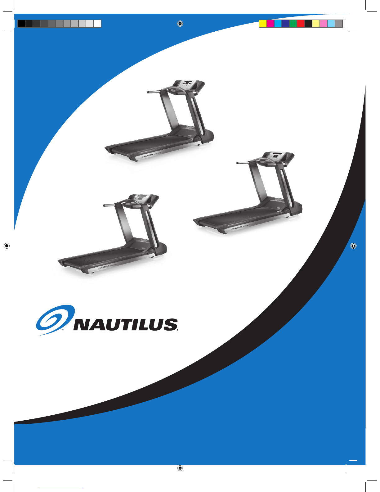
Nautilus Sport, Be Strong Sport T514, Be Strong Sport T516, Be Strong Sport T518 Assembly Manual
Page 1
Base Model: T514, T516, T518
Display Model: LE, LE-X, LC
Sport SerieS
ASSEMBLY MANUAL
Be Strong.
™
Model : T514
Model : T516
Model : T518
P/N: 00 0- 4844 Rev D (12/ 2005)
Page 2

Page 3

All treAdmillS Are not creAted equAl.
I
Nautilus® Sport Series Treadmill Assembly Manual
SI MPL ICI T Y
Our treadmills are so
well designed that they’re
simple to use. Touch one
key and go.
WHISP ER- Q UIE T DES IGN
With the sturdy steel frame
and stable platform, you
can expec t smooth, quiet
performance mile after mile.
BU ILT FO R THE LON G RUN
These cutting-edge machines
are patterned after our
commercial treadmills, which
you’ll find in gyms worldwide.
35-YEA R H ER ITAG E
Nautilus has been at the
forefront of the fitness
industry since there’s been
a fitness industry.
Thank you for purchasing your Nautilus® Sport Series treadmill. For more than 30 years Nautilus has been producing
the world’s finest fitness equipment used in health clubs and homes around the globe. We hope this product meets your
every expectation and is a valuable tool on the road to accomplishing all your fitness goals.
Please carefully read through this manual to familiarize yourself with the assembly of your new Nautilus® treadmill.
Doing so will help to ensure you get the most use out of your treadmill, with enjoyable workouts in the comfort of your
home.
Nautilus, Inc.
World Headquarters
16400 S.E. Nautilus Drive
Vancouver, Washington, USA 98683
1-800-NAUTILUS (1-800-628-8458)
Fax (800) 898-9410
Nautilus.com
PREFACE
Page 4
II
tAble of contentS
PRODUCT SERIAL NUMBER LOCATIONS 1
PRODUCT SPECIFICATIONS 2
IMPORTANT SAFETy PRECAUTIONS 3
BEFORE yOU ASSEMBLE 5
PARTS LIST 6
HARDWARE AND TOOL LIST 7
BASE ASSEMBLy GUIDE 8
DISPLAy ASSEMBLy GUIDE 19
WARRANTy 23
IMPORTANT CONTACT NUMBERS 24
For detailed instructions and inFormation on how
to use and care For your nautilus
®
sport series
treadmill, model t514, t516 and t518, reFer to the
owner’s manual.
7 ! 2 . ) . '
! 4 4 % . 4 ) / .
$ ! . ' % 2
Page 5
1
Nautilus® Sport Series Treadmill Assembly Manual
product SeriAl number locAtionS
DI SPLAY SERI AL NUMB ER LOCATIO N
(NOR TH A MERI CA ONLY)
The display serial number is located on the back
side of the display module. The display serial
number is present on units sold in North America.
The display serial label is only visible when the
display is detached from the base.
For units sold outside of North America, please
refer to the base serial number as described in the
Base Serial Number Location section.
In North America, the serial number and model
number listed on the decal located on the back
side of the display are required when completing
the enclosed warranty card and may be required
when calling Customer Service.
BASE SERI AL NUMB ER LOCATIO N
The serial number decal on the base can
be found on the left hand incline arm. This
decal is visible without removing any parts
on the treadmill. To more easily view the
serial number decal, incline the treadmill to
15%.
The serial number and model number listed
on this decal are required when completing
the enclosed warranty card and may be
required when calling Customer Service.
All Sports Series treadmills have a serial
label located on the base.
Serial Number Decal Location
LE Display
Serial Number Location
LE-X Display
Serial Number Location
LC Display
Serial Number Location
Regulatory Approvals
Meets:
Safety - EN 60335-1,
EMC Directive 89/336/EEC - European Union (EU),
EN 61000-6-3
EN 61000-6-1
Meets:
UL1647 3rd Ed
CSA C22.2 No. 68-92 CAN
Patent Information
U.S. and International Patents Pending
Page 6

2
product SpecificAtionS
Treadmill deck PlaTforms
T514 T516 T518
Continuous HP 2.7 HP 3.0 HP Hyperdrive® Technology 3.0 HP Hyperdrive® Technology
User Weight Limit 350 lbs (159 kgs) 375 lbs (170 kgs) 375 lbs (170 kgs)
Maximum Grade 15% 15% 15%
Running Surface 20” x 57” ( 51cm x 1.4m) 20” x 57” (51cm x 1.4m) 20” x 60” ( 51cm x 1.5m)
Belt Ply Two Ply SuperSoft® Deck SuperSoft® Deck
Padding REACT® Deck REACT® Deck REACT® Deck
Board Surface Phenolic-Rev Phenolic-Rev Phenolic-Rev
Power Inlets Front Front Front and Rear
ROC™ Bar N/A N/A Standard
Grip Heart Rate N/A N/A Yes
Physical Dimensions
Width 30.1” (76cm) 30.1” (76cm ) 30.1” (76cm)
Length 82.8” (2.1m) 82.8” (2.1m) 85.8” (2.1m)
Height 18” (45cm) 18” (45cm) 18” (45cm)
Machine Weight 325 lbs 325 lbs 325 lbs
Shipping Weight 350 lbs 375 lbs 375 lbs
console disPlays
le le-X lc
Languages English English, French, English, French,
German, Spanish German, Spanish
Workout Programs 6 Preset, 2 Custom 9 Preset, 3 Custom 12 Preset, 3 Custom
Heart Rate Strap Yes Yes Yes
Heart Rate Program 2 Incline Controlled 2 Incline Controlled 2 Incline Controlled
Speed Range 0.5 - 12 MPH 0.5 - 12 MPH 0.5 - 12 MPH
( 0.8 - 19.3 KPH) (0.8 - 19.3 KPH) ( 0.8 - 19.3 KPH)
Optional Workout Software N /A My Nautilus™ Software, My Nautilus™ Software,
Heart Strong™ Software, Heart Strong™ Software,
My Nautilus™ LX My Nautilus™ LX
Shipping Weight Approx. 6 lbs Approx. 6 lbs Approx. 6 lbs
Page 7
3
Nautilus® Sport Series Treadmill Assembly Manual
importAnt SAfety precAutionS
When using electrical equipment, always follow these
basic precautions:
IMPORTANT SAFETY INSTRUCTIONS
The following definitions apply to the word “Warning” found
throughout this manual:
Used to call attention to potential
hazards that could result in personal
injury or loss of life.
READ ALL INSTRUCTIONS BEFORE USING
THE MACHINE.
1. Do not plug the treadmill into an outlet until the final assembly
is complete and the motor cover is installed.
2. CONSULT YOUR PHYSICIAN BEFORE STARTING ANY EXERCISE
PROGRAM. Only he or she can determine the exercise program
that is appropriate for your particular age and condition. If
you have not been exercising or are pregnant or have a heart
condition or any physical limitation, failure to consult your
physician before engaging in physical exercise, such as using a
Nautilus® Sport Series treadmill , could result in serious injury
or death. If while using a Nautilus® Sport Series treadmill
you have any pain or tightness in your chest, an irregular heart
beat, shortness of breath, feel faint, light-headed or dizzy or
have any pain or discomfort, STOP and consult your physician
immediately.
3. Read, understand, and test the SAFETY STOP PROCEDURES in
the Owner’s Manual before using the treadmill.
4. The Safety Stop Cord does not turn off the electrical current
to the treadmill. The treadmill continues to draw power, even
when the display is off. To avoid electric shock, do not remove
treadmill motor covers or place hands beneath the treadmill
while the treadmill is plugged into a power source.
5. Review all of the warning labels on the treadmill before use.
6. The Nautilus® Spor t Series Treadmill, models T514, T516
and T518 are intended for home use only. The T514 maximum
user weight limit is 350 pounds (159 kilograms). The T516
and T518 maximum user weight limit is 3 75 pounds (170
kilograms) . Do not exceed the maximum user weight limits.
7. Before each use of this equipment, inspect the treadmill for
incorrect, worn, or loose components. The machine can be
safely used only when it is regularly inspected for damage or
wear. Inoperable components should be replaced, repaired, or
tightened immediately, or the equipment should be taken out
of use until repairs have been made.
8. Do not wear any loose or dangling clothing or jewelry while
using the Nautilus® Sport Series treadmill. Always keep your
hands, feet, clothing, etc. clear from beneath the treadmill and
from all moving parts. Never use your treadmill with the Motor
Cover or Frame Covers removed.
9. Always wear rubber-soled athletic shoes on the Nautilus®
Sport Series treadmill. Never use the treadmill barefooted or
wearing only socks.
10. Do not start the treadmill when someone is standing on
the belt. Always stand on the foot rails on each side of the
walking belt when starting the treadmill. Be careful when
mounting or dismounting the treadmill.
11. Keep speed and incline at the lowest settings when someone
is get ting on and off the treadmill.
12.
Keep the area underneath and around the treadmill clear.
Position the treadmill on a clean, level surface and do not
place the treadmill on t hick carpet as it may interfere with
proper ventilation. We recommend the use of a treadmill mat
that may be purchased from your treadmill dealer or Nautilus,
Inc.
To reduce the risk of electrical shock, always unplug the
external power supply from the electrical outlet before
cleaning, maintaining, or repairing.
To reduce the risk of burns, electric shock, or injury to
persons: Read this manual in full before operating the
treadmill. Failure to follow these guidelines can produce
a serious or possibly fatal electrical shock hazard or other
serious injury. Consult a qualified electrician as required.
7 ! 2 . ) . '
7 ! 2 . ) . '
Page 8

4
importAnt SAfety precAutionS
13. Never position the treadmill with the back end (direction of
belt travel) facing a wall or any other objects such as furniture
or other pieces of fitness equipment. Failure to do so can
prevent safe exit of the treadmill in an emergency situation
such as falling. Allow a minimum of 79 inches ( 2 meters)
behind the treadmill and 20 inches (.5 meters ) on each side.
14. Before each use of this equipment , check the power cord,
plug, plug receptacle and outlet for signs of damage. If any of
them appears frayed, loose, worn, or otherwise faulty, or if
the insulation appears worn or cracked, do not operate the
machine. Position the treadmill so that the wall plug is visible
and accessible. If the power cord is damaged, it must be
replaced with a power cord from Nautilus, Inc.
15. To avoid potential safety and electrical problems, replace wi th
manufacturers’ specified parts only.
16. Always disconnect the treadmill from the power outlet before
cleaning, maintaining, servicing, or removing the motor cover.
17. This equipment is classified Class I, Type B, ordinary
equipment. Not protected against fluid ingress. Rated for
continuous operation. Do not operate this equipment in the
presence of flammable anesthetic mix tures.
18. Do not let liquid enter the display or motor/controller area. If
liquid enters either area, the area(s) must be inspected and
tested for safety by an approved technician before it can be
used again. Do not place the treadmill near water or outdoors.
Do not use the machine in damp or wet conditions.
19. Increased risk due to leakage of electrical current may result if
this equipment is not grounded properly.
20. The treadmill must be on an appropriate, dedicated electrical
circuit carrying 15 amps (110 Volt model) or 7 amps (22 0 Volt
model). Nothing else should be connected to the circuit . Use
of a surge protector is recommended.
21. Do not stand on treadmill motor cover or front trim cover.
22. Parents and others in charge of children should be aware that
children, because of their natural play instinct and fondness for
experimenting, may be tempted to situations and behavior for
which the equipment is not intended, with resulting damage to
the equipment and injury to the children or others. Children’s
access to the equipment should therefore be controlled, and
they should be instructed about the potential for personal injury
and damage if they play with the equipment.
Failure to follow the conditions set forth below shall limit , to the
extent allowed by law, Nautilus® Inc. responsibility for the safety,
reliability, and performance of this equipment.
• Each user must read the Owner’s Manual in full before using
the product. Each user must read, unders tand, and carefully
follow all warnings, instructions, and procedures regarding
the proper use of the treadmill and its accessories.
• Do not remove the treadmill motor covers: dangerous voltages
are present. Component s such as the motor, controller, and
display are serviceable only by qualified service personnel.
• The electrical wiring within the treadmill setting and the
electrical installation of the treadmill must comply with the
applicable local or provincial requirements.
• The equipment must be used in accordance with the
instructions for use.
• For further information or instruction on use, maintenance
or specifications, please contact your Authorized
Nautilus®
Retail Outlet.
Page 9

5
Nautilus® Sport Series Treadmill Assembly Manual
before you ASSemble
Basic Assembly Principles
Here are few basic assembly tips that can make
assembly of your
Nautilus® Sport Series treadmill
quick and easy.
1. You can make the assembly process go faster
by gathering the pieces you need for each step
prior to starting the step.
2. As a general rule, and for all fasteners on your
Nautilus® Sport Series treadmill, turning toward
the right will tighten, turning towards the left
will loosen. An easy way to remember this is
by remembering the expression, “Lefty loosey,
righty tighty.”
3. The hex key and Phillips screwdriver tools
needed to assemble your Nautilus® Sport Series
treadmill are provided.
During the assembly
process a 1/2 inch Socket with Ratchet will also
be required. This tool is not provided. You may
find the use of a utility knife or scissors beneficial
during the unpacking process.
4. It is recommended that you use two people to
assemble your Nautilus® Sport Series treadmill.
Select Your Workout Area
Select where you are going to put your Nautilus®
Sport Series treadmill carefully. The best place for
your treadmill is on a hard, level surface. You will
need at least 20 inches (.5 meters) on each side of
the treadmill and 79 inches (2 meters) behind your
treadmill for dismount.
Make sure that the location you choose has a
grounded, 3-prong power outlet within reach of
the treadmill power cord.
NOTE: The Nautilus® Sport Series treadmill is
designed to plug into a grounded, non-GFI outlets
only. To determine if your outlet or circuit breaker
is GFI, look for a test and reset button on them.
If they have the test and reset button it is a GFI
outlet or circuit breaker.
Further, if you ever perform any repairs on your
treadmill that require you to lay it on its side, you
will need at least five feet to one side of your
workout area.
Machine Mat
The Nautilus® Machine Mat is an optional
accessory for the Nautilus® Sport Series treadmill
that helps keep your workout area free from debris
and dust. The rubber machine floor mat provides
a non-slip surface for you to use when mounting
and dismounting the treadmill and limits static
discharge when you touch the machine—greatly
reducing the possibility of display or running errors.
Further, a rubberized mat will protect your flooring
when you are performing repairs or maintenance
on the treadmill.
Put your Nautilus® Machine Mat in place in your
selected workout area before you start assembly
to protect your floors and your treadmill from
damage.
Positioning Your Nautilus® Sport Series
Treadmill
Take great care when moving your treadmill into
place prior to assembly.
There are two rear end caps on either side of the
walking belt for lifting of the base and two wheels
on either side of the front of the base beneath the
console. It is highly recommended that you do not
attempt to ever lift or move the treadmill without
help.
When you assemble the Nautilus® Sport Series
treadmill, you will need at least two people to set
the base in place, and lift the handlebar assembly.
Page 10
6
ASSEMBLY GUIDE
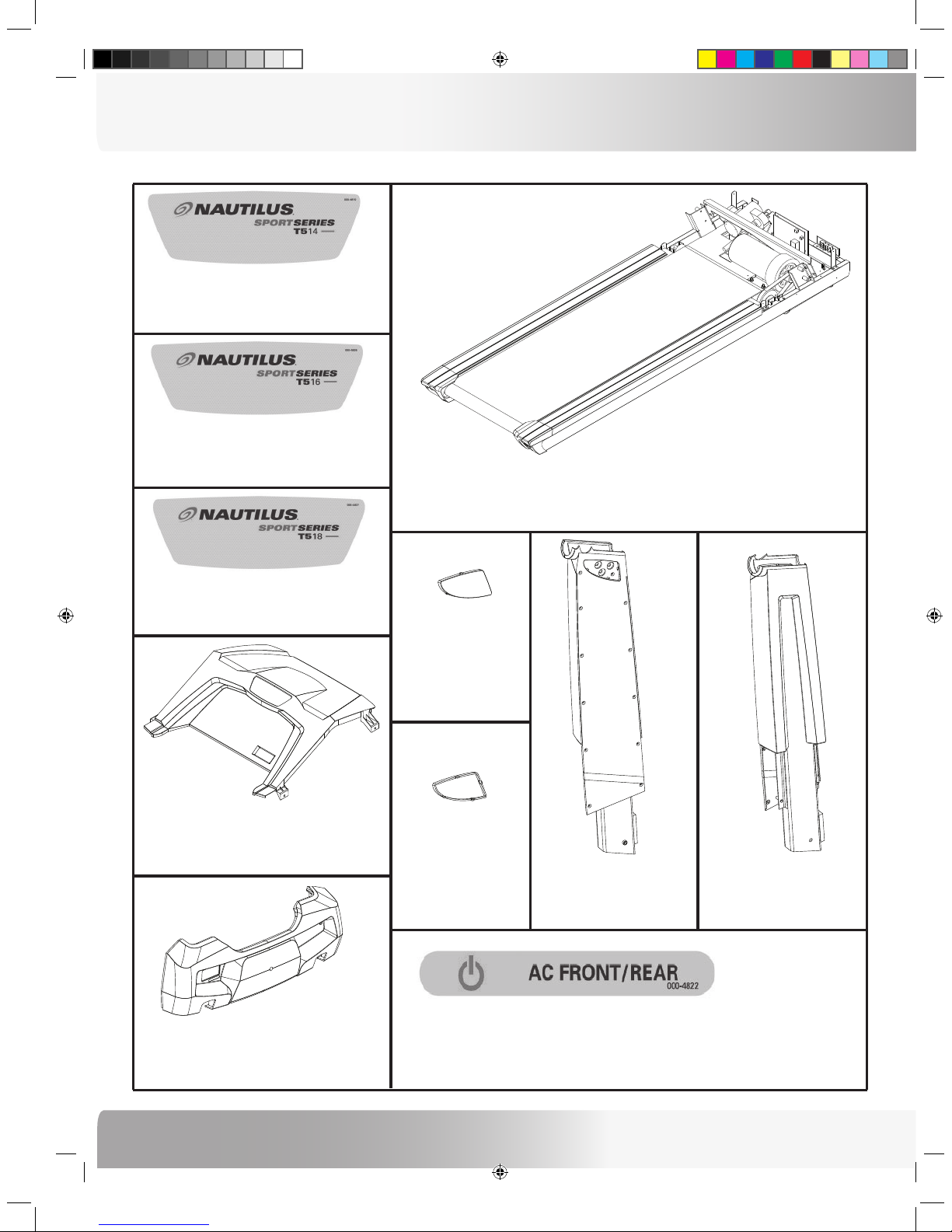
pArtS liSt
Part : Base Frame Assembly
Qty: 1
Part : Right Upright Assembly
Qty: 1
P/N : 00 0-4785
Part : Lef t Upright Assembly
Qty: 1
P/N : 00 0-4786
Part : Top Plastic Motor Cover
Qty: 1
P/N : 00 0-4696
Part : Top Motor Cover Sticker (T518)
Qty: 1
P/N : 00 0-4827
Part : Top Motor Cover Sticker (T516)
Qty: 1
P/N : 00 0-4826
Part : Front Plastic Motor Cover
Qty: 1
P/N : 00 0-4695
Part : Lef t Upright Cap
Qty: 1
P/N : 00 0-4725
Part : Right Upright Cap
Qty: 1
P/N : 00 0-4724
Part : Front Motor Cover Sticker (T518)
Qty: 1
P/N : 00 0-4822
Part : Top Motor Cover Sticker (T514)
Qty: 1
P/N : 00 0-4810
Page 11

7
Nautilus® Sport Series Treadmill Assembly Manual
pArtS liSt
Part : Front Motor Cover Sticker (T514/516)
Qty: 1
P/N : 00 0-48 33
Part : Console Assembly
Qty: 1
P/N : Model T514: 000- 4796 /Model T516: 000-4829 / Model T518: 0 00 -4798
Part : Lef t Upright Motor Cover
Qty: 1
P/N : 00 0-4700
Part : Right Upright Motor Cover
Qty: 1
P/N : 00 0-4697
Part : Rear Console Access Panel
Qty: 1
P/N : 00 0-4718
Part : LC Display Front ( shown in co nsole)
Qty: 1
P/N : 00 0-4706
Part : LE-X Display Front (shown in con sole)
Qty: 1
P/N : 00 0-4706
Part : LE Display Front (show n in console )
Qty: 1
P/N : 00 0-4722
Page 12

8
ASSEMBLY GUIDE
HArdwAre And tool liSt
During the assembly process a 1/2 socket with ratchet will be required. This tool is not provided.
HARDWARE BAG (P/N: 000-4775) - NOTE: ILLUSTRATIONS ARE NOT TO SCALE.
The Hardware Bag contains the following individual parts and tools.
Item: Hex Head Bolts (5/16 - #18 x2)
Qty: 2
P/N: HH2052
Item: Hex Head Bolts (5/16 - #18 x 1 1/2)
Qty: 4
P/N: HH2168
Item: Flat Washers (5 /16)
Qty: 6
P/N: HH 2154
Item: Phillips Flat Head Screws (#8 x 3/4)
Qty: 8
P/N: HH2611
Item: Pan Head Stainless Steel Screws (#10 x 5/8)
Qty: 10
P/N: HH2612
Item: Nylon Washers (5/16)
Qty: 3
P/N: MM 2105
Item: Hex Head Bolt (5/16 - #18 x 1)
Qty: 6
P/N: HH2164
Item: Phillips Pan Head Self Drilling Metal
Screws (#8 x 3/4)
Qty: 11
P/N: HH 2555
Item: Star Washers (5 /16)
Qty: 3
P/N: HH 2408
Item: Plastic Hex Key Clip
Qty: 1
P/N: MM 0087
Item: Flat Washer (5/16) - 1/2 inch outer diameter
Qty: 6
P/N: HH2458
Item: 3/16 inch Hex Key
Qty: 1
P/N: HH2001
Item: Phillips Screw Driver
Qty: 1
P/N: HH 2435
Page 13

9
Nautilus® Sport Series Treadmill Assembly Manual
Step 1: Attaching Uprights to Base Assembly
Locate the following for this step:
Parts:
• Base Assembly
• Left Upright Assembly
• Right Upright Assembly
Hardware:
• 4 Hex Head Bolts (5/16 - #18 x 1-1/2)
• 2 Hex Head Bolts (5/16 - #18 x 2)
• 6 Flat Washers (5/16)
1-1 Place Base Assembly in the location you want the
final assembled treadmill.
1-2 Install Left Upright Assembly onto Base Assembly
using 2 of the 5/16 - #18 x 1-1/2 hex head bolts and
2 flat washers on the front side of the assembly
and 1 hex head bolt (5/16 - #18 x 2) on the outside
of the assembly. Hand Tighten Bolts Only.
The following instructions provide direction in assembling the base units for the Nautilus® Sport Series
treadmill models T514, T516 and T518. All instructions in the manual are given with the orientation of standing
on the treadmill facing the console. The console is the front, while the rear roller is the back.
bASe ASSembly guide
Figure 1: Step 1 Upright Assembly
Left Upright Assembly
Right Upright Assembly
Base Assembly
Bolt
Washer
Front Cross Support Bracket
2” Hex Bolt
1-1/2” Hex Bolt s
Page 14

10
ASSEMBLY GUIDE
bASe ASSembly guide
Step 2: Tightening Motor Pan Bolts
Locate the following for this step:
Parts:
• Assembly from Step 1
Tools:
• 1/2 inch Socket with ratchet (not provided)
2-1 Tighten the factory installed motor pan bolts
before proceeding with assembly.
Figure 2: Step 2 Tightening Motor Pan Bolts
Motor Pan Bolts
Base Assembly
Motor Pan Bolts
Step 1: Continued
NOTE: You may need to loosen the motor pan bolts
(see Step 2 for location) and move the front
cross support bracket towards the front of
the base assembly for the Upright Supports
to fully fit onto the brackets.
1-3 Verify that the wiring harness connectors are
accessible at the top and bottom of the Right
Upright Assembly.
1-4 Install Right Upright Assembly onto Base Assembly
using 2 of the 5/16 - #18 x 1-1/2 hex head bolts and
2 flat washers on the front side of the assembly
and 1 hex head bolt (5/16 - #18 x 2) on the outside of
the assembly. Hand Tighten Bolts Only.
Page 15

11
Nautilus® Sport Series Treadmill Assembly Manual
Step 3: Connecting the Wiring Harness
Locate the following for this step:
Parts:
• Assembly from Step 2
• Console Assembly
3-1 Connect wiring harness from the bottom of the
right upright to the Lower Control Board by routing
the cable through the Motor Pan Wiring Clip
located on the Base Assembly and connecting the
6-pin and 8-pin connectors.
3-2 Connect the wiring harness from the top of the
right upright to the connector in the right handrail
of the console assembly, matching the 6-pin and
8-pin connectors.
bASe ASSembly guide
Figure 3: Step 3 Connecting Wiring Harness
3-1: Motor Pan
Wiring Clip
& Wiring
Connections
IMPORTANT!
MAK E SUR E THAT
THE C ABL ES
CAN NOT COM E INT O
CO N TACT W ITH A N Y
MO VIN G PA RTS B Y
SE CUR IN G T HE M
IN T H E MO TO R PA N
WI RIN G CLI P BE FOR E
PR OCE ED ING .
3-2 : Console
Wiring
Connections
Use caution when connecting the
wiring harness to ensure that the
wires do not become pinched or
come into contact with any moving
part. The treadmill will not work
and an electric shock hazard may be
present.
7 ! 2 . ) . '
Page 16

12
ASSEMBLY GUIDE
bASe ASSembly guide
Step 4: Placing the Console Assembly
Locate the following for this step:
Parts:
• Assembly from Step 3
• Console Assembly
4-1 Slide Console Assembly mounting Bracket into
Upright Supports.
Figure 4: Step 4 Placing Console Assembly
IMPORTANT!
MAK E SUR E THAT
THE C ABL ES D O N OT
BE COM E PI N CH ED
BE T W EE N T HE
CO NSO LE AN D T HE
RI GHT U PRI GHT
AS S EM BLY.
Base Assembly
Console Assembly
7 ! 2 . ) . '
! 4 4 % . 4 ) / .
$ ! . ' % 2
# ! 5 4 ) / .
Only for Base Model T518 - Use caution to
NOT SHEAR off the plastic (Lexan) strips on
the left side console bracket when sliding
the console onto the Upright Tubes. To do
so, could cause damage to the Heart Rate
module functioning properly.
Page 17
13
Nautilus® Sport Series Treadmill Assembly Manual
Step 5: Securing the Left Side on Console Assembly
Locate the following for this step:
Parts:
• Assembly from Step 4
Hardware:
• 3 Hex Head Bolts (5/16 - #18 x 1)
• 3 Nylon Washers (5/16)
• 3 Flat Washers (5/16) - 1/2 inch outer diameter
Tools:
• 1/2 inch Socket with ratchet (not provided)
5-1 Fasten console onto Left Upright support using 3
bolts, flat and nylon washers.
5-2 Tighten all bolts on the left side securely, including
Upright Support bolts installed in Step 1 .
Figure 5: Step 5 Securing Console Assembly
Hex Head Bolt
Nylon Washer
Flat Washer
bASe ASSembly guide
IMPORTANT!
MAK E SUR E THAT
THE N YLO N WA SHER
RAI SED E DG E IS NE X T
TO T HE UP RI GHT
SU PPO RT DU RIN G
IN S TALL ATI ON. S EE
HAR DWARE S TACK I N
FI GUR E 5.
Page 18

14
ASSEMBLY GUIDE
bASe ASSembly guide
Step 6: Securing the Right Side on Console Assembly
Locate the following for this step:
Parts:
• Assembly from Step 5
Hardware:
• 3 Hex Head Bolts (5/16 - #18 x 1)
• 3 Flat Washers (5/16) - 1/2 inch outer diameter
• 3 Star Washers (5/16)
Tools:
• 1/2 inch Socket with ratchet (not provided)
6-1 Fasten console onto Right Upright support using 3
bolts, 3 flat washers and 3 star washers.
6-2 Tighten all bolts on the right side securely,
including Upright Support bolts installed in Step 1 .
Figure 6: Step 6 Securing Console Assembly
Hex Head Bolt
Flat Washer
Star Washer
IMPORTANT!
MAK E SUR E THAT
THE S TA R WA SHER IS
NE X T T O THE U PRIGH T
SU PPO RT DU RIN G
IN S TALL ATI ON. S EE
HAR DWARE S TACK I N
FI GUR E 6.
Page 19

15
Nautilus® Sport Series Treadmill Assembly Manual
bASe ASSembly guide
Step 7: Installing Upright Hardware Caps
Locate the following for this step:
Parts:
• Assembly from Step 6
• Left Upright Hardware Cap
• Right Upright Hardware Cap
7-1 Install Left Upright Hardware Cap.
7-2 Repeat process for Right Upright Hardware Cap.
Figure 7: Step 7 Installing Upright Caps
Page 20

16
ASSEMBLY GUIDE
bASe ASSembly guide
Step 9: Installing Front Motor Cover Sticker
Locate the following for this step:
Parts:
• Assembly from Step 8
• Top Motor Cover Sticker
9-1 Wipe area beneath AC inlet on Front Motor Cover
with clean dry cloth.
9-2 Carefully adhere the Top Motor Cover sticker (see
illustrations below) to the area and rub to remove
any air bubbles.
Step 8: Installing Top Motor Covering
Locate the following for this step:
Parts:
• Assembly from Step 7
• Top Plastic Motor Covering
8-1 Place top plastic piece onto mounting points.
Figure 8: Step 8 Installing Top Motor Cover
Top Motor Cover
Figure 9: Step 9 Top Motor Cover Sticker
Top Motor Cover Sticker Location
T514 Top Motor Cover Sticker T516 Top Motor Cover Sticker
T518 Top Motor Cover Sticker
Page 21

17
Nautilus® Sport Series Treadmill Assembly Manual
bASe ASSembly guide
Step 10: Installing Left & Right Upright Covers
Locate the following for this step:
Parts:
• Assembly from Step 9
• Left Upright Cover
• Right Upright Cover
Hardware:
• 8 Self Drilling Metal Screws (#8 x 3/4)
• 8 Phillips Flat Head Screws (#8 x 3/4)
Tools:
• Phillips Screw Driver
10-1 Install Left Upright Cover using 4 Phillips Flat
Head Screws on the inside of the Left Upright
Support Assembly.
10-2 Install 4 Self Drilling Metal Screws on the outside
of the Left Upright Support Assembly and Left
Upright Cover.
10-3 Repeat process for Right Upright Cover.
Figure 10: Step 10 Installing Upright Covers
Left Upright Cover
Right Upright Cover
Upright Support Assembly
Self Drilling
Metal Screws
Page 22

18
ASSEMBLY GUIDE
bASe ASSembly guide
Step 11: Installing Front Motor Covering
Locate the following for this step:
Parts:
• Assembly from Step 10
• Front Plastic Motor Covering
Hardware:
• 3 Self Drilling Metal Screws (#8 x 3/4)
Tools:
• Phillips Screw Driver
11-1 Install Front Plastic Motor covering onto the Base
Assembly using 3 Self Drilling Metal Screws.
Figure 11: Step 11 Installing Front Motor Cover
Front Motor Cover
Base Assembly
Page 23

19
Nautilus® Sport Series Treadmill Assembly Manual
bASe ASSembly guide
Step 12: Installing Front Motor Cover Sticker
Locate the following for this step:
Parts:
• Assembly from Step 11
• Front Motor Cover Sticker
12-1 Wipe area beneath AC inlet on Front Motor Cover
with clean dry cloth.
12-2 Carefully adhere the Front Motor Cover sticker
(see illustrations below) to the area and rub to
remove any air bubbles.
Figure 12: Step 12 Front Motor Cover Sticker
Front Motor Cover Sticker Location
T514 & T516: Front Motor Cover Sticker
T518 : Front Motor Cover Sticker
Step 13: Inspecting Base Assembly
Congratulations!
Now that you have assembled your Nautilus® Sport
Series treadmill base, Model T514, T516 or T518, it
is VERY IMPORTANT to tighten all screws and bolts,
and visually inspect the treadmill. If your treadmill sits
unevenly you may adjust the rear feet with a wrench
to make the treadmill stable on your floor. Make sure
that your treadmill has been assembled correctly and
securely, and that there are no loose, uncovered or
unattached parts prior to assembling the display.
Failure to visually check and test
assembly before use can cause
damage to the Nautilus® Sport
Series treadmill and serious injury to
users and bystanders and can also
compromise the effectiveness of your
exercise program.
7 ! 2 . ) . '
Page 24

20
ASSEMBLY GUIDE
The following instructions provide direction in completing the console units for the Nautilus® Sport
Series treadmill displays LE, LE-X and LC. All instructions for assembling the display are given with
the orientation of standing on the treadmill facing the console. The console is the front, while the rear
roller is the back.
Step 1: Locating the Wiring Harness
Locate the following for this step:
Parts:
• Sport Series Treadmill Base Platform
1-1 Locate the Wiring Harness from the Console
Assembly to the display.
Figure 1: Step 1 Locating Wiring Harness
Wiring Harness
diSplAy ASSembly guide
Page 25

21
Nautilus® Sport Series Treadmill Assembly Manual
diSplAy ASSembly guide
Step 2: Installing Display into Console Assembly
Locate the following for this step:
Parts:
• Treadmill Assembly from Step 1
• Display
Hardware:
• 4 Stainless Steel Screws (#10 x 5/8)
Tools:
• Phillips Screw Driver
2-1 Install Display into Console Assembly.
2-2 Secure the Display with 4 Stainless Steel screws.
Figure 2: Step 2 Installing Display
Console Display
Console Assembly
IMPORTANT!
MAK E SUR E THAT TH E
WI RIN G HAR N ES S
CAB LES DO NO T
BE COM E PI N CH ED.
Page 26

22
ASSEMBLY GUIDE
diSplAy ASSembly guide
Figure 3: Step 3 Connecting Wiring Harness
Step 3: Connecting the Wiring Harness
Locate the following for this step:
Parts:
• Treadmill Assembly from Step 1
3-1 Connect the Wiring Harness from the Console
Assembly to the display, making sure to match the
pin connectors.
NOTE: The LE Display Connections:
NOTE: The LE-X Display Connections:
NOTE: The LC Display connections:
LE Display Back
LE-X Display Back
LC Display Back
Page 27

23
Nautilus® Sport Series Treadmill Assembly Manual
diSplAy ASSembly guide
Step 4: Installing Rear Access Panel
Locate the following for this step:
Parts:
• Treadmill Assembly from Step 3
• Rear Access Panel
Hardware:
• 6 Stainless Steel Screws (#10 x 5/8)
Tools:
• Phillips Screw Driver
4-1 Install Rear Access Panel using 6 Stainless Steel
screws.
CONGRATULATIONS!
Assembly of your Nautilus® Sport Series Treadmill is
now complete.
Be sure to fully inspect your Nautilus® Sport Series
treadmill before plugging in and using for the first
time.
Please refer to your Nautilus® Sport Series Treadmill
Owner’s Manual for information on proper use of your
treadmill and calibration.
For more information visit our web site Nautilus.com
or call 1-800-NAUTILUS (1-800-628-8458).
Figure 4: Step 4 Installing Rear Access Panel
Failure to visually check and test
assembly before use can cause
damage to the Nautilus® Sport
Series treadmill and serious injury to
users and bystanders and can also
compromise the effectiveness of your
exercise program.
7 ! 2 . ) . '
Page 28

24
ASSEMBLY GUIDE
LIMITED WARRANTY
All Nautilus® exercise products are warranted to the
retail purchaser to be free from defects in materials
and workmanship. Warranty coverage valid to the
original purchaser only and proof of the purchase will be
required. Any product sold or placed in an application not
recommended by Nautilus, Inc. will void any warranty
coverage set forth by Nautilus, Inc. warranty policies and
procedures. This treadmill is for home use only.
Time Period:
Frame: Lifetime
All parts and electrical parts: 10 Years
Labor and wear parts: 1 Year
What this warranty does not cover:
1. Any component on original equipment which carries
a separate consumer warranty of the parts supplier.
2. Use in commercial setting such as health clubs,
schools, hotels and hospitals.
3. Treadmills used by users weighing more than the
maximum user weight limit of 350 lbs (159 kgs)
for the T514 and 375 lbs (170 kgs) for the T516 and
T518.
4. Any damage, failure or loss caused by accident,
misuse, neglect, abuse, improper assembly,
improper maintenance, failure to follow instructions
or warnings in Owner’s Manual or disaster (such as
floods or power surges).
5. Use of product in an application not recommended
by Nautilus, Inc. or in a manner or environment for
which it was not designed.
6. Damage due to normal wear and tear.
Limitations:
The preceding warranties are the sole and exclusive
express warranties made by Nautilus, Inc. They supersede
any prior, contrary or additional representations,
whether oral or written. No agent, representative,
dealer or employee has the authority to alter or increase
the obligations or limitations of this warranty. Any
implied warranties, including the WARRANTY OF
MERCHANTABILITY and any WARRANTY OF FITNESS
FOR A PARTICULAR PURPOSE, are limited in duration
to the term of the applicable express warranty provided
above, whichever is longer. Some states do not allow
limitations on how long an implied warranty lasts, so the
above limitation may not apply to you.
What Nautilus will do:
Nautilus, Inc. liability hereunder is expressly limited to the
replacement of goods not complying with this warranty or,
at Nautilus, Inc. election, to the return of the purchase price
of the exercise product in question. THESE REMEDIES
ARE THE EXCLUSIVE AND SOLE REMEDIES FOR ANY
BREACH OF WARRANT Y. Nautilus, Inc. shall in no event
be liable for incidental or consequential losses, damages or
expenses in connection with its exercise products. Some
states do not allow the exclusion or limitation of incidental
or consequential damages, so the above limitation may not
apply to you
Procedures:
Warranty service will in most cases be performed by an
authorized Nautilus® Fitness Dealer or Service Technician.
The original purchaser must provide proof of purchase.
Service calls and /or transportation to and from the
Nautilus® Dealer is the responsibility of the purchaser.
1. Nautilus, Inc. will have the option to repair or replace
any exercise product, which requires service.
2. Nautilus, Inc. will replace any equipment frame
that is structurally defective with a new frame or
replace the unit with a unit of equal value. Nautilus,
Inc. is not responsible for labor charges in replacing
defective frames.
3. Nautilus, Inc. is not responsible for dealer labor
charges for the component change overs completed
after the labor related warranty period stated herein.
4. If you elect to repair an exercise product or part
yourself, using the services of someone other than
an authorized Nautilus® Fitness Dealer or Service
Technician, or use a replacement part not supplied
by Nautilus, Inc., Nautilus Inc. shall not be liable for
any cost, damage, failure or loss caused by the use
of such unauthorized service or parts.
Warranty Registration (For the US and Canada Only):
1. Complete the warranty card that is enclosed with the
treadmill’s base and assembly guide and send via US
mail or Canada Post, OR
2. Register online at http://www.nautilus.com/warranty.
Click on Nautilus warranty registration.
List both the base model number and the display model
number on the serial card. For example, list “T514 LE” for
the model number if you purchased the T514 base and the
LE display.
Page 29

25
Nautilus® Sport Series Treadmill Assembly Manual
importAnt contAct numberS
OFFICES IN THE UNITED STATES:
• TECHNICAL/CUSTOMER SERVICE
Nautilus, Inc.
World Headquarters
16400 SE Nautilus Drive
Vancouver, Washington, USA 98683
Phone: 800-NAUTILUS (800-628-8458)
Email: customerservice@nautilus.com
Fax: 800-523-1049
• MANUFACTURING FACILITY
Nautilus, Inc.
12032 Highway 155 North
Tyler, Texas, USA 75708
Phone: 800-NAUTILUS (800-628-8458)
Fax: 903-877-4113
• CORPORATE HEADQUARTERS
Nautilus, Inc.
World Headquarters
16400 SE Nautilus Drive
Vancouver, Washington, USA 98683
Phone: 800-NAUTILUS (800-628-8458)
If you need assistance, please have both the serial number
of your machine and the date of purchase available when
you contact the appropriate Nautilus office listed below.
For technical assistance and a list of distributors
in your area, please call or fax one of the following
numbers.
INTERNATIONAL CUSTOMER SERVICE:
• INTERNATIONAL OFFICE
Nautilus International S.A.
Rue Jean Prouvé 6
1762 Givisiez / Switzerland
Tel: + 41-26-460-77-77
Fax: + 41-26-460-77-70
Email: technics@nautilus.com
INTERNATIONAL OFFICES:
• SWITZERLAND OFFICE
Nautilus Switzerland S.A.
Tel: + 41-26-460-77-66
Fax: + 41-26-460-77-60
• GERMANY and AUSTRIA OFFICE
Nautilus GmbH
Tel: +49-2204-610-27
Fax: +49-2204-628-90
• ITALY OFFICE
Nautilus Italy s.r.l.
Tel: +39-031-51-10-86
Fax: +39-031-34-24-97
• UNITED KINGDOM OFFICE
Nautilus UK Ltd.
Tel: +44-1908-267-345
Fax: +44-1908-267-346
• CHINA OFFICE
Nautilus Representative Office
Tel: +86-21-523-707-00
Fax: +86-21-523-707-09
Page 30

Page 31

Page 32

Be Strong.
™
For more information about our Spor t Series treadmills or other Nautilus®
equipment for your home, visit w ww.Nautilus.com/ SportSeries.
© 200 5 Nauti lus, Inc. A ll right s reserv ed. Naut ilus, the N autilus l ogo, My Nau tilus, H eart St rong, Cha nging the Ga me in Healt h and Fit ness, RE ACT, RO C, Remot e Operati on Contr ol, Super Soft , Hyper drive, Be S trong
are eit her regis tered tr ademarks o r tradema rks of Naut ilus, Inc .
Nauti lus, Inc. Wo rld Headqu arter s, 164 00 SE Naut ilus Dri ve, Vancouv er, Washing ton, US A 9868 3, 1-8 00- 628- 845 8, ww w.Naut ilus.co m.
P/N: 00 0- 4844 Rev D (12/ 2005)
Model : T514
Model : T516
Model : T518
 Loading...