

Page 1
P/N 19-1034 07-24-14
® ®
Owner’s Instructions
STRONGER THAN EVER
™
And Assembly Of The
U10 And R10 Commercial Bikes
Core Fitness, exclusive manufacturer of
®
Nautilus
Commercial Fitness Equipment
Page 2

Page 3
PREFACE
3
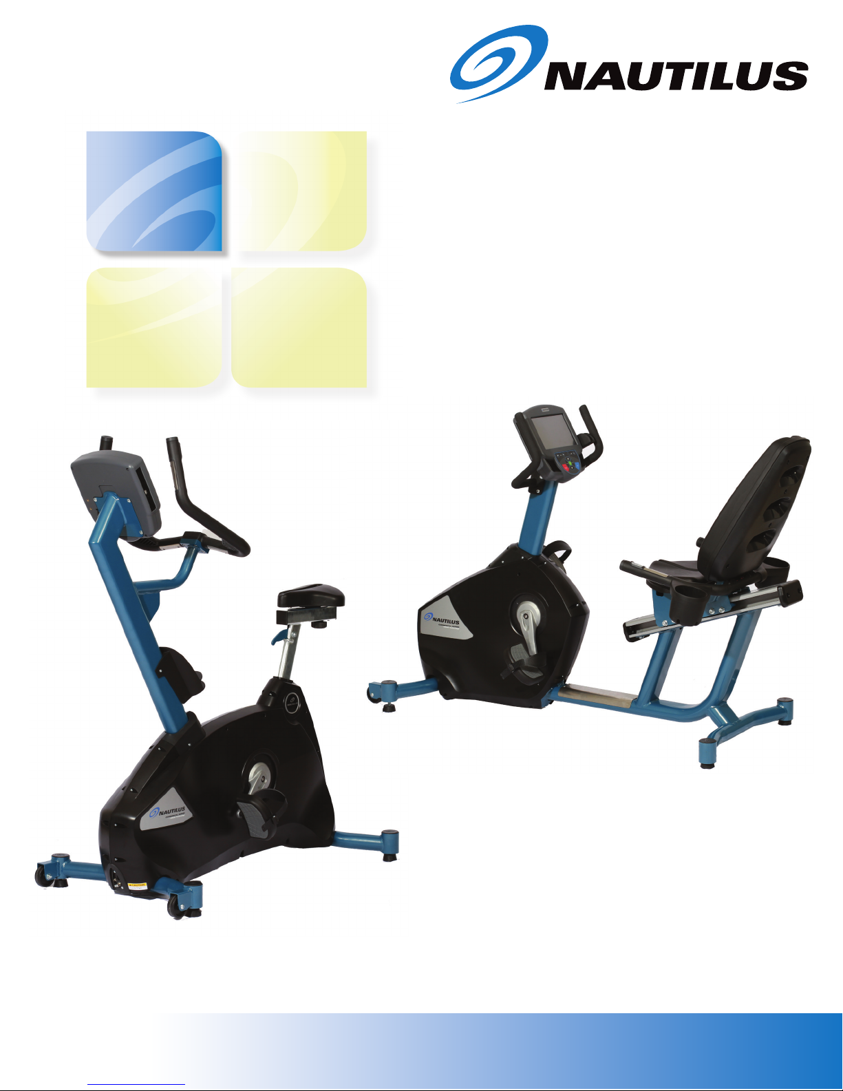
Thank you for purchasing the Nautilus® Commercial Series U10 Upright Bike or R10 Recumbent
®
Bike. For more than 30 years, Nautilus
used in health clubs and homes around the globe. We hope this product exceeds your expectations and is a valuable tool for your facility and your customers.
Please carefully read through this manual to familiarize yourself with the operation of your new
U10 or R10 Commercial Bike. Doing so will help ensure that your customers get the most out of
the machine, and enjoy safe and effective workouts ahead.
Thanks again!
has been producing the world’s finest fitness products
Core Fitness
Corporate Headquarters
4400 NE 77th Ave
Vancouver, WA 98662
800-235-2233
www.stairmaster.com
Page 4

TABLE OF CONTENTS
4
Important Safety Instruction ...........................................................................
Product Specifications ....................................................................................
Model Information .........................................................................................
Regulatory Compliance ................................................................................
EU Representative .......................................................................................
Safety Warning Decals .................................................................................
Getting Started .................................................................................................
Installation Notice .........................................................................................
Guidelines For Safe Operation .....................................................................
Guidelines For Getting On And Off ..............................................................
Heart Rate Monitoring ..................................................................................
U10 And R10 Assembly ...................................................................................
Tools And Components ................................................................................
Receiving .....................................................................................................
5
6
6
6
6
7
9
9
9
10
11
12
12
13
Moving .........................................................................................................
Unpacking And Assembling .........................................................................
Scanning For TV Channels ..........................................................................
Touchscreen Console Operation ...................................................................
Page Flow And Structure .............................................................................
The Keypad .................................................................................................
Workout Pages ............................................................................................
Programs ......................................................................................................
Setup Pages ................................................................................................
U10 And R10 Maintenance .............................................................................
Contact Information ........................................................................................
Notes ................................................................................................................
13
13
19
18
18
18
19
31
45
56
59
60
Page 5

IMPORTANT SAFETY INSTRUCTIONS - SAVE THESE INSTRUCTIONS
5
This icon means a potentially hazardous situation exists which, if not avoided, could
result in death or serious injury.
When using an electrical appliance, basic precautions should always be followed, including the
following:
1. Read all instructions before using this appliance.
2. DANGER - To reduce the risk of electric shock, always unplug this appliance
from the electrical outlet immediately after using and before cleaning.
3. WARNING - To reduce the risk of burn, fire, electric shock, or injury to persons:
• This appliance should never be left unattended when disconnected from the
outlet. It should remain connected to the outlet at all times, except when putting
on or taking off parts;
• Close supervision is necessary when this appliance is used near children,
invalids, or disabled persons;
• This appliance should never be used by children, invalids, or disabled persons;
• Use this appliance only for its intended use as described in the Owner’s
Manual. Do not use attachments not recommended by the manufacturer;
• Never operate this appliance if it has a damaged cord or plug, if it is not working
properly, if it has been dropped or damaged, or if it has been dropped into
water. If the cord is damaged, it must be replaced using the special cord or
assembly available exclusively from the manufacturer;
• Keep the cord away from heated surfaces;
• Never drop or insert any object into any opening of this appliance;
• Do not use this appliance outdoors;
• To disconnect the appliance, turn all controls to the “off” position, then remove
the plug from the outlet.
4. WARNING - Connect this appliance to a properly grounded outlet in accordance
with all local codes and ordinances.
Page 6

PRODUCT SPECIFICATIONS
6
Model U10 Upright Bike
Dimensions: 27” W x 47” L x 60” H (69cm x 119cm x 152cm)
Unit Weight: 158 lbs (72kg)
Shipping Package Weight: 218 lbs (99kg)
Workout Area: 50” W x 81” L (127cm x 206cm)
Power Adaptor Rating: 100V~ to 240V~, 50/60 Hz, 1.5A Input
Maximum User Weight: 400 lbs (182kg)
Model R10 Recumbent Bike
Dimensions: 24” W x 67” L x 46” H (61cm x 170cm x 117cm)
Unit Weight: 180 lbs (82kg)
Shipping Package Weight: 231 lbs (105kg)
Workout Area: 50” W x 103” L (127cm x 262cm)
Power Adaptor Rating: 100V~ to 240V~, 50/60 Hz, 1.5A Input
Maximum User Weight: 400 lbs (182kg)
Regulatory Compliance
Meets FCC Part 15, Class B
Complies with the following EU Directives (product bears the CE mark):
Machinery Directive 2006/42/EC
Low Voltage Directive 2006/95/EC (tested per EN 60335-1:2002 + A14:2010)
EMC Directive 2004/108/EC (tested per EN 61000-6-3 and EN 61000-6-1)
RoHS Directive 2011/65/EU
WEEE Directive 2002/96/EC
Meets EN 55011 for Australia and New Zealand (product bears the C-Tick mark)
EU Representative
Core Fitness, LLC
Unit 4
The Gateway Centre, Coronation Road
Cressex Business Park
High Wycombe, Bucks
HP12 3SU UK
Page 7
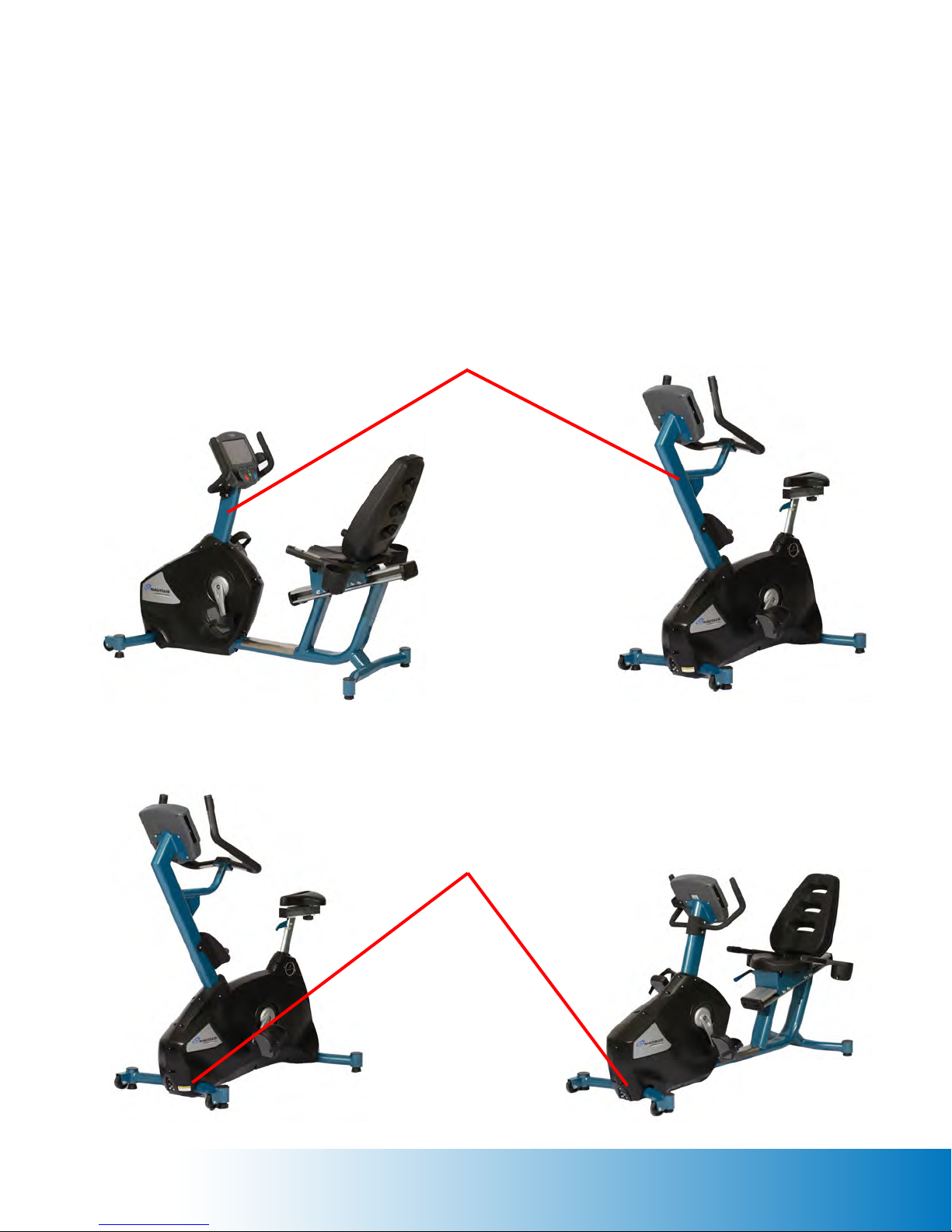
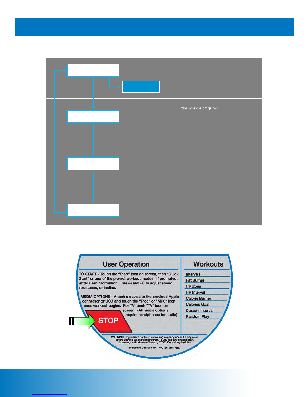
Safety Warning Decals
7
Safety warnings are located on the U10 and R10 Commercial Bikes as shown below. Please
read all safety precautions and warning information prior to using the machines. Be sure to
replace any safety warning decal that is damaged, illegible, or missing. For replacement decals,
please contact a Core Fitness Customer Excellence representative at 800-235-2233, or
276-773-2881 outside the United States.
Decal #1 Location
Decal #2 Location
Page 8
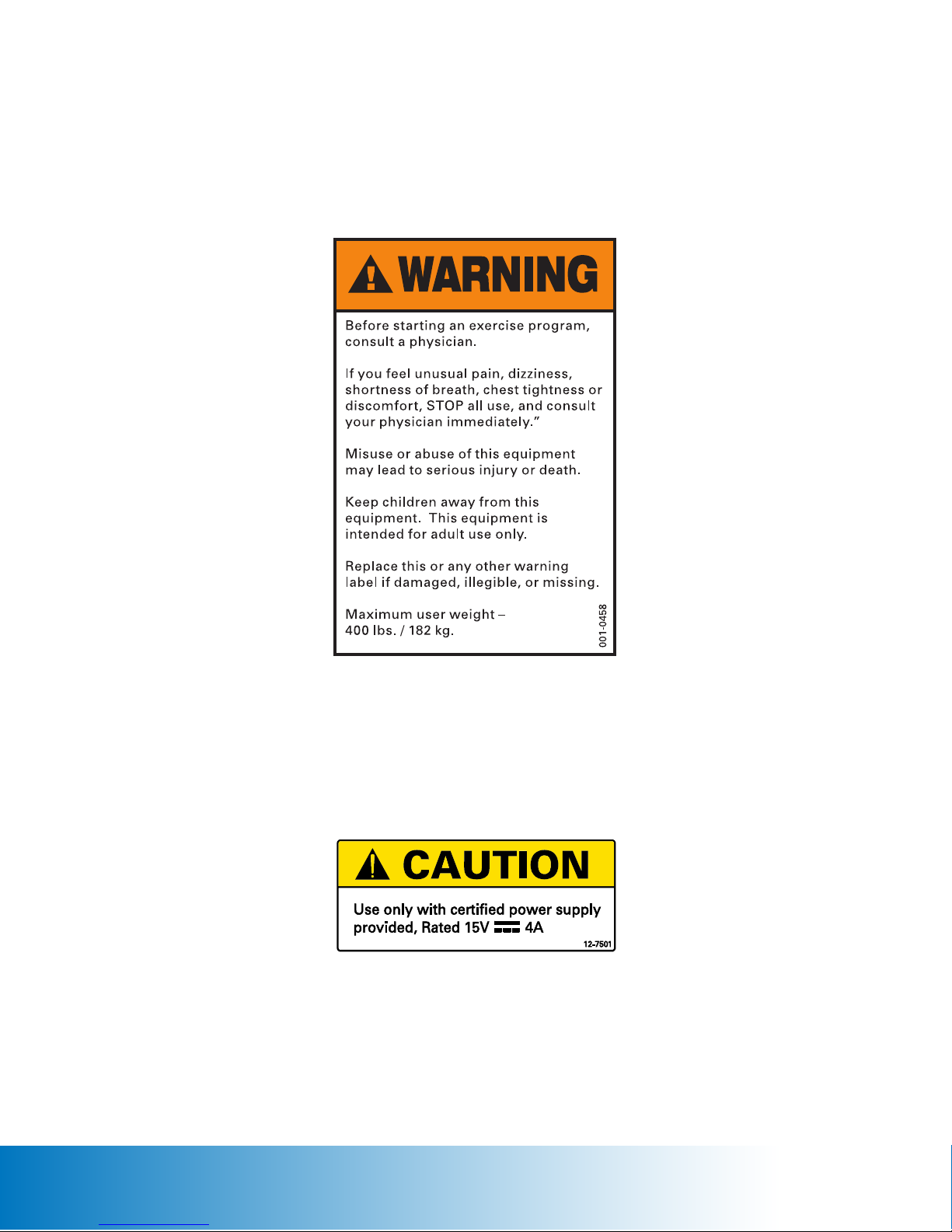
Safety Warning Decals continued
8
Decal #1 - General Warnings
Decal #2 - Power Caution
Page 9

GETTING STARTED
9
Installation Notice
The U10 and R10 Commercial Bikes must be properly installed before being used. Core Fitness
recommends that you contact your dealer or sales representative when your machine arrives.
The representative will help unpack, install, and demonstrate proper use of the machine to
ensure that the machine is free from shipping damage, and that installation and operation are
in accordance with Core Fitness standards.
The owner’s instruction manual must be read in full by each owner and trainer before the machine
is first used. Each user must be instructed in the proper use of the machine and its accessories.
Guidelines For Safe Operation
1. Obtain a complete physical examination from your medical doctor and enlist a health/
fitness professional’s aid in developing an exercise program suitable for you current health
status.
2. Secure long hair and loose clothing before using the machine.
3. When working out for the first time, use the Manual exercise program at lower levels until
you feel comfortable and capable of higher workloads.
4. The intensity and duration of your exercise program should always be subject to how you
feel. Never permit peer pressure to override your personal judgement while exercising.
5. Overweight or severely deconditioned individuals should be particularly cautious when
using the machine for the first time. Even though such individuals may not have histories of
serious physical problems, they may perceive the exercise to be far less intensive than it
really is, resulting in the possibility of overexertion or injury.
6. Although all products manufactured by Core Fitness have been thoroughly inspected prior
to shipment, proper installation and regular maintenance are required to ensure safety.
Inoperable components should be replaced immediately or the machine be put out of use
until it is repaired. Maintenance is the sole responsibility of the owner.
WARNING - If you have not been exercising regularly, consult a physician before
starting an exercise program. If you feel any unusual pain, dizziness, or shortness of
breath, STOP, and consult a physician.
Page 10

Guidelines For Getting On And Off The U10 And R10 Commercial Bikes
10
To avoid injury, carefully follow these instructions.
1. Adjust the pedal straps to ensure your feet will be properly secured to the pedals during
your workout. Position your foot so that the ball of your foot is over the pedal spindle. The
pedal straps should be tight enough to secure your foot, but not so tight as to cut off circulation.
2. Hold on to the upper handlebars and step across the center frame tube.
3. Sit on the seat, place your feet into the pedal straps, and begin to pedal slowly. Stop pedaling
while one leg is extended and your foot is as close to the floor as possible. Adjust the seat so
that your knee is slightly bent while your leg is extended.
4. Tap Press To Start on the console display.
5. Tap Manual to select the Manual exercise program so you can control the pace of your first
workout and become familiar with the exercise motion.
6. The console will prompt you to enter your body weight. Select your weight in pounds (or
kilograms if the console is set to metric units).
7. The console will prompt you to enter a resistance level. Select a resistance level from 1
(very easy) to 20 (extremely difficult). First time users should select a low resistance level (for
example, select level 2 or 3).
8. The console will prompt you to enter the total workout time. Select a time from 2 to 99
minutes.
9. Tap Start to begin the workout. If you do not begin exercising within 1 minute, the console
will end the workout and advance to the report page.
10. As you become comfortable with the exercise motion, tap Level + or Level – to adjust the
resistance level.
11. Relax during your workout. Supporting your weight with the handlebars while exercising
decreases the intensity.
12. Make sure the pedals come to a complete stop before dismounting the machine. Hold on
to the upper handlebars, carefully place one foot on the floor, and then place your other foot
on the floor.
Page 11

Heart Rate Monitoring
11
Heart rate monitoring helps users monitor their levels of exertion by displaying their heart rate
during exercise. There are two methods of monitoring heart rate on the U10 and R10
Commercial Bikes:
• Contact Heart Rate - heart rate can be checked at any time during a workout by using the
stainless steel sensors built into the ergobar handgrips. The sensors detect the heart beat
signal and display it on the touchscreen console.
• Telemetry Heart Rate - a transmitter belt worn across the chest transmits the heart beat to a
receiver in the console. The heart beat signal is displayed on the console.
Contact Heart Rate (CHR)
CHR signals are acquired only during contact between your hands and the stainless steel
sensors in the handgrips. Place your hands around the handgrips so that your hands touch both
the top and bottom sensors. After initial contact, the receiver requires a valid heart beat signal
within ten to fifteen seconds. During validation, the receiver will not recognize a telemetry signal.
The console will display a “beating” heart icon and the heart rate value in beats per minute.
If during the exercise the heart rate value becomes erratic, it may be helpful to remove your
hands from the sensors and begin again. The CHR system’s ability to detect a heart beat signal
is influenced by: movement of the upper body which may produce an electrical signal (muscle
artifact) that will interfere with the heart beat signal detected by the sensors; movement of the
hands while they are in contact with the sensors producing interference; calluses and hand lotion
acting as an insulating layer to reduce the signal strength. Some individuals may not generate
a heart beat signal strong enough to be detected by the sensors; these individuals should opt
for Telemetry Heart Rate monitoring.
Telemetry Heart Rate
The Telemetry function is activated as soon as you step within range of the receiver while
wearing the transmitter belt across your chest. Two electrodes on the underside of the belt
sense the heart beat signal and transmit it to the receiver. After initial contact, the receiver
requires four valid heart beat signals lasting four seconds in order to lock on telemetry for
the duration of the workout. The console will display a “beating” heart icon and the heart rate
value in beats per minute.
Wet the two electrodes before putting on the transmitter belt. Secure the belt as high under the
pectoral muscles as is comfortable. The belt should fit snugly while allowing for normal breathing.
If your heart rate is not being displayed: move closer to the console; tighten the belt around your
chest; adjust the belt higher or lower on your chest; remoisten the electrodes; or test the belt
on a machine that has previously displayed the heart rate.
Page 12
Tools And Components
assembly questions? call 800-235-2233 for help.
12
U10 AND R10 ASSEMBLY
U10 Fasteners Included:
(3) 10-32 x 3/4 SS Pan Head Screw
(4) 3/8-16 x 1 Socket Head Screw
U10 Components Included:
(1) Mast Assembly
(1) Seat Slide Assembly
(1) LH Mast Shroud
(1) RH Mast Shroud
(4) Leveling Pad
(1) Touchscreen Console
(1) 15V Global Power Supply
U10 Tools Required:
Shears or Razor Knife
7/16 Hex Socket and Ratchet
R10 Fasteners Included:
(6) 10-32 x 3/4 SS Pan Head Screw
(4) 3/8-16 x 1 Socket Head Screw
(4) 1/2-13 x 3/4 Hex Head Screw
(4) 1/2 Internal Lock Washer
R10 Components Included:
(1) Mast Assembly
(1) Seat Assembly
(1) LH Mast Shroud
(1) RH Mast Shroud
(5) Leveling Pad
(1) Touchscreen Console
(1) 15V Global Power Supply
R10 Tools Required:
1/8 Allen Wrench
5/16 Allen Wrench
#2 Phillips Screwdriver
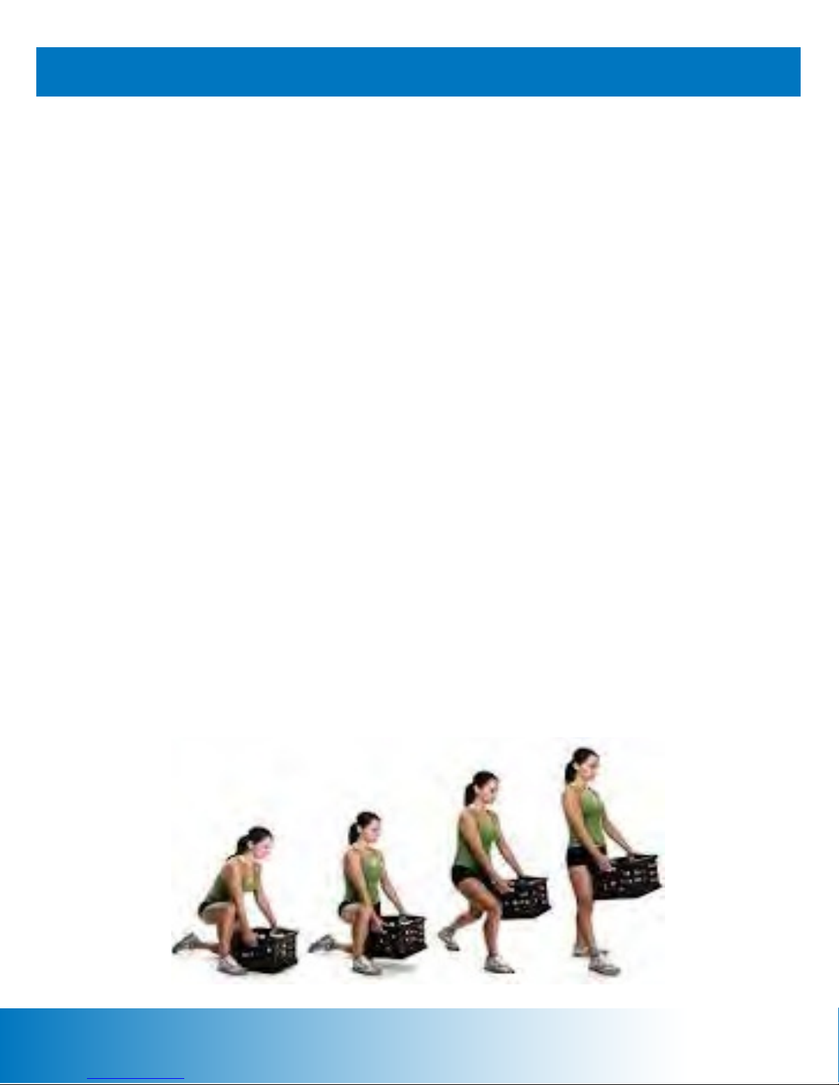
Proper Lifting Technique
Shears or Razor Knife
7/16 Hex Socket and Ratchet
3/4 Hex Socket and Ratchet
5/16 Allen Wrench
#2 Phillips Screwdriver
Page 13

Receiving
assembly questions? call 800-235-2233 for help.
13
When the carrier delivers your order, verify that the number and type of items matches what is
listed on the freight bill or express receipt.
Inspect the containers for damage. Itemize discrepancies and damage on the waybill and have
the carrier sign it. Failure to adequately describe external evidence of loss may result in the
carrier refusing to honor the claim. Do not discard the packing materials until you have verified
physical condition and proper operation.
Moving The U10 And R10 Commercial Bikes
The U10 and R10 Commercial Bikes are heavy and awkward, and require two people to safely
move them from one location to another. With the help of another person, lift up the rear of the
machine until the front transport wheels are in contact with the floor. The machine can now be
safely rolled on the transport wheels. Note: the transport wheels are intended for indoor use only
and should not be rolled on concrete or asphalt surfaces.
Assembly Questions
If you have any questions or concerns regarding the assembly process, please contact a
Core Fitness Customer Excellence representative at 800-235-2233, or 276-773-2881 outside
the United States.
Unpacking And Assembling The U10 And R10 Commercial Bikes
1. Inspect the containers for damage as described above.
2. Use shears or a razor knife to cut the straps securing the box cover to the pallet. Remove
the cover and set it aside.
3. Remove the packing materials from around the machine.
4. Use shears or a razor knife to cut the straps securing components and the parts box.
Remove the components and the parts box, and set them aside.
5. Use the 7/16 socket and ratchet to loosen the bolts securing the frame assembly to the pallet.
6. With the help of another person, move the frame assembly off of the pallet and place it on
the floor near the desired location for use.
7. Remove the packing materials from around the frame assembly.
Page 14
Figure 1
assembly questions? call 800-235-2233 for help.
14
8. With the help of another person, tilt the frame assembly to one side to provide adequate
clearance for installation of the leg levelers. You can place a block of wood or other such
support under the frame assembly for stabilization. Insert the leg levelers into the front and
rear support tubes as shown in Figure 1. The R10 also requires a leg leveler in the center
frame tube.
9. Adjust the leg levelers so that they contact the floor with approximately the same number of
threads showing. In some case, one or two of the leg levelers may have less, or more, threads
showing depending on the levelness of the floor. Secure the jam nut against the support tube
to lock the leg leveler in place.
10. Place the mast assembly near the mast mounting plate on the frame assembly. Connect
the attached black wire tie to the main harness (20-pin connector), CHR harness (4-pin
connector), and TV coaxial cable. Carefully pull on the wire tie to draw the harnesses and cable
through the mast assembly. Pull the excess harness and cable out of the access hole.
11. Position the mast assembly against the mast mounting plate so that the holes are aligned.
Secure the mast assembly to the mast mounting plate using the (4) 3/8-16 hex head screws.
Take care not to pinch the harnesses and cable. Use the 5/16 allen wrench to tighten.
Page 15
12. Identify the lefthand and righthand mast shrouds. Position the shrouds around the mast
assembly questions? call 800-235-2233 for help.
15
assembly so that the holes are aligned. Secure the shrouds to the assembly using the (3)
10-32 pan head screws. Use the #2 phillips head screwdriver to tighten.
13. (for U10 only) The seat slide assembly has two 1/4-20 set screws. Use the 1/8 allen
wrench to loosen and remove the front set screw. Insert the seat slide assembly into the seat
bracket and then re-install the set screw.
14. (for R10 only) Place the seat assembly near the seat mounting plate. Connect the harness
from the seat assembly to the harness from the frame assembly.
15. (for R10 only) Position the seat assembly against the seat mounting plate so that the holes
are aligned. Secure the seat assembly to the seat mounting plate using the (4) 1/2-13 hex head
screws and (4) 1/2 lock washers. Take care not to pinch the harnesses. Use the 3/4 hex socket
and ratchet to tighten.
16. Release the main harness (20-pin connector), ergo harness (4-pin connector) (U10 only),
both contact heart rate harnesses (5-pin connector), and the TV coaxial cable from the console
mounting plate. Pull the excess harness and cable out of the access hole.
17. Place the rear of the touchsreen
console near the mounting plate so that
the harnesses and cable can be connected.
18. Connect the main harness to the
console at JP3 as shown in Figure 2.
19. Connect the righthand contact heart
rate harness to the console at J3 as shown
in Figure 2.
20. (for U10 only) Connect the ergo
harness to the console at J12 as shown in
Figure 2.
21. Connect the lefthand contact heart
rate harness to the console at J4 as shown
in Figure 2.
22. Connect the TV coaxial cable to the
console using the supplied female-tofemale connector. Note that 7” consoles are
not TV ready and will not have a coaxial
cable connection.
23. Route the iPod cable through the access
slot in the rear of the console housing.
Figure 2
Main Harness To JP3
RH CHR Harness To J3
U10 Ergo Harness To J12
LH CHR Harness To J4
Page 16

24. Remove the (6) 1/4-20 pan head screws
assembly questions? call 800-235-2233 for help.
16
from the rear of the console. Position the
console against the mounting plate so that the
holes are aligned. Secure the console to the
mounting plate using (4) 1/4-20 pan head
screws as shown in Figure 3. Use the #2
phillips head screwdriver to tighten.
25. Position the iPod holder against the
console so that the holes are aligned.
Secure the iPod holder to the console using
(2) 1/4-20 pan head screws. Use the #2
phillips head screwdriver to tighten.
NOTE: Do not connect the 15V power supply to the machine until
the console has been installed! If the console must be removed
and disconnected for any reason, ensure that the power supply is
disconnected first!
Figure 3
Page 17
Scanning For TV Channels (10” consoles only)
assembly questions? call 800-235-2233 for help.
17
When using the TV function for the first time, the console must scan for available TV channels.
Follow the instructions below to perform the TV channel scan.
1. Ensure the coaxial cable is connected to
the console as described on the previous
page.
2. Connect the power supply to the
machine at the front power inlet and then
connect it to the wall or floor outlet.
3. From the Splash Page, touch and hold
the Nautilus icon for 5 to 10 seconds to
advance to the Setup Page as shown in
Figure 4.
4. Tap the Customize icon to advance to
the Customize Page.
5. Tap the Next icon to advance to Page 3
Figure 4
6. Tap the Auto Scan icon to begin the TV
channel scan as shown in figure 5.
7. When the channel scan is 100%
complete, tap the Back icon once to return
to the Setup Page. Then tap the Exit icon
to return to the Splash Page.
Figure 5
Figure 6
Page 18
TOUCHSCREEN CONSOLE OPERATION
(re po rt
18
Console Page Flow And Structure
Main Menu
Setting Page
Workout Page
Report Page
SETUP Page
Program list:
Th e user is able to choose the desired exercise
p rogr a m ; SETUP pag e ca n b e e nte re d fr o m th is
scree n.
Settin g
According to the program chosen, the user is
pro mpted to set the required parameters to
begin workout.
The screen automatica lly displays the exercise
program after entering the parameters.
Multi-Media functions can be accessed on this
scre en.
Once the workout is completed,th e system
automatically displays the workout results
p age ) inc luding t ime, calories, heart rat e, &
distance.
The Keypad
Press the Stop
Button to pause
the current
program. Press
the Stop Button
again to end the
program.
Page 19

Splash Page
19
The Splash Page allows the user to access the Setup Page to change default settings, update
software files, view maintenance information, etc. To advance to the Setup Page, touch and
hold the Nautilus icon for 5 to 10 seconds.
The user can also advance to the Main Program Page by tapping on the Press To Start icon.
FU N CTION N AM E ACTI ON
Setup Page Entry Touch and hold the Nautilus icon to
advance to the Setup Page
Press To Start Tap the Press To Start icon to advance
to the Main Program Page
RESULT
Setup Page displayed
Main Program Page displayed
Page 20

HR Zone
Main Program Page (Basic Exercise Programs)
20
FUNCTION NAME ACTION RESULT
Quick Start Tap the Quick Start icon to enter the workout page Workout Page displa yed
Manual Tap the Manual icon to enter the settingpage Setting Page displayed
Fat Burner Tap the Fat Burner icon to enter the setting page Setting Page displayed
Calorie Tap the Calorie icon to enter the setting page Setting Page displayed
Intervals Tap the Intervals icon to enter the setting page Setting Page displayed
HR Zone Tap the HR Zone icon to e nter t he setting page Setting Page displayed
More Tap the More icon to see more exer ci se pr ogram More exercise programs
displayed on the left hand
side
Close Close the Program Circle Program Circle disappears
Quick Start
Manual
Fat Burner
Calorie More
Intervals
Page 21

More Programs Page (More Exercise Programs)
21
FUNCTION NAME ACTION Action
Fitness Test Tap the Fitness Test icon to enter the Fitness Test Menu Fitness Test Menu page
displayed
Custom Intervals Tap the Custom Intervals icon to enter the setting
page
Random Play Tap the Random Play icon to ente r the setting page Setting Page displayed
Heart Rate Interval Tap the Heart Rate Interval icon to enter the
Checking for Heart Rate Page
Fitness Test Calories Goal Custom Intervals Random Play HR IntervalMore
Setting Page displayed
Checking for Heart Rate
Page displayed
Page 22

Program Settings Page
22
The settings data requests in the Settings Page may be different depending on the
requirements for each program.
FUNCTION NAME ACTION RESULT
Body Weight Value entered
Level Value entered
Total Time
Back
Start
Body Weight
Press + - to adjust the value
Tap the Back icon
Tap the Start icon
Age
Workout
Value entered
Back to the Main Menu
Enters the Workout Page and
begins the exercise
Total Time
Page 23

Workout Page
23
After selecting a program and entering settings data, the workout begins immediately. The user
can adjust the resistance level manually and access multimedia functions.
DISPLAY NAME ACTION
METs Displays the total METs (Multiple of the resting metabolic rate)
WATTS Displays the accumulated Watts
Time Displays the accumulated work out t ime
Calories Displays the accumulated calories burn ed
Distance Displays the accumulated distance rode
Heart Rate (bpm) Displays the received Heart Rate Beat
Speed (km/hr) Displays the current speed (km/hr)
RPM Displays the RPM
Interval Time Displays the remaining time w ithin each interval (Count Down)
Level Displays commanded LEVEL
Range of Level: 1 ~ 20
le Chart Blue bar: Displays the anded level.
Black bar: Displays the comin g in terval with commanded level.
Page 24

Workout Page continued
24
FUNCTION ACTION RESULT
LEVEL Tap the + button to increase level.
(1~20)
LEVEL Tap the - button to decrease level.
(1~20)
SPORT Tap the SPORT button to back to the original
workout page.
MP3 Tap the MP3 button to play MP3. • MP3 play list box displayed
iPOD • Tap the iPOD button to play iPOD.
• iPod / iPhone should be connected.
TV • Tap the TV button to watch TV.
• TV cable sho uld be connected.
Fan Low /
High / Auto
Tap tton to run fan Fan Low button displayed
Tap the Fan Low button to run fan Fan High button displayed
Tap the Fan High button to run fan Fan Auto button displayed, the wing blow
Tap the Fan Auto button to run fan Fan Closed
Resistance will be adjust ed according to the
entered value.
Resistance will be adjust ed according to the
entered value.
Media display disappears, bar chart displayed.
• Detect le
• iPOD play list box displayed
• Detect iPOD device
TV screen displayed (full screen)
changes according to the intensity of exercise.
Pause • Tap the Pause button to pause the running
program.
• It the machine is paused over 30 seconds,
stops the machine.
• Program paused temporarily.
• Pause button => STOP
• Quick Start button => Continue
Page 25

Workout Page continued
25
Function Action Result
THR Tap the TH R + - icons to adjust the Target Heart
Rate
Stop Tap the Stop icon to stop the workout. Workout is terminated. Report
Continue Tap the Continue icon to continue the workout Workout is continued.
Sport
MP3
iPod
The Target Heart Rate will change
according to the value entered.
Page displayed.
TV
Page 26

Report Page
26
Function Action Result
Next Tap the Next icon to the next Report page Next Report page shows
Previous Tap the Previous icon back to the last page Last Report page shows
Exit Tap the Exit icon to exit Report page. Back to Main Menu
Page 27

TV / Video Page
27
The TV / Video Page will display a TV channel or video over the entire Workout Page. Tap
anywhere on the page to display the control bar across the bottom of the screen; tap the page
again to hide the control bar.
Note: The touchscreen console is not equipped with internal speakers. External speakers or
earphones are required to listen to audio playback.
FUNCTION NAME ACTION RESULT
BACK Tap the Back button to leave t he TV / Video
screen and back to the Wo rkout Page
CH UP Tap the Channel Up button to change channel Channel changed
CH DOWN Tap the Channel Up button to cha nge channel Channel changed
VOL UP Tap the Volume Up to increase the volume Volume adjusted
VOL DOWN Tap the Volume Down to decrease the volume Volume adjusted
• TV / Video stops playing
• Workout page shows
Page 28

MP3 Page
28
The MP3 Page will hover over the Workout Page until the user chooses another function.
Note: The touchscreen console is not equipped with internal speakers. External speakers or
earphones are required to listen to audio playback.
FUNCTION ACTION RESULT
Previous Tap the PREVIOUS icon to play the previous track Previous music played
Next Tap the NEXT icon to play the next track Next music played
Volume Down Tap the VOLUME DOWN icon to decrease volume Voice lower
Volume Up Tap the VOLUME UP icon to increase volume Voice loud er
Pause Tap the PAUSE icon to stop the media temporarily PLAY icon displayed. Tap the
PLAY icon to resume.
Sport
MP3
iPod
TV
Page 29

iPod Page
29
The iPod Page will hover over the Workout Page until the user chooses another function.
Note: The touchscreen console is not equipped with internal speakers. External speakers or
earphones are required to listen to audio playback.
FUNCTION ACTION RESULT
Back Arrow Tap the Back Arrow to go b a ck to the last page Back to the lastpage
Pla y lists Tap the Play lists icon to view ava ilable media Playlists displayed
Artists Tap the Artists icon to see the artist list Artist list displayed
Albums Tap the Albums icon to see the album list Album list displayed
Songs Tap the Songs icon to see t he song list Song listdisplayed
Videos Tap the Videos icon to see the video list Video list displayed
Page Up Tap the Page Up icon to se e the listat the top The top list displayed
Page Down Tap the Page Down icon to see more list More play list displayed
Sport
MP3
iPod
TV
Page 30

iPod Page continued
30
FUNCTION ACTION RESULT
Backward Tap the PREVIOUS icon to play the previous track Previous music played
Forward Tap the NEXT icon to play the nexttrack Next music played
Volume Down Tap the VOLUME DOWN icon to decrease volume Voice down
Volume Up Tap the VOL UME UP icon to increase volume Voice up
Pause Tap the PAULSE icon to stop the music PLAY icon shows. Tap the PLAY
icon to start the music
Blue Arrow Tap the Blue Arrow icon to go back to the last page . iPod Playlist displayed
Sport
MP3
iPod
TV
Page 31

Quick Start Program
31
WORKOUT PAGE:
1. Step rate may be changed anytime.
a. Tap the LEVEL + button to increase the resistance.
b.
Tap the LEVEL - button to decrease the resistance.
2. New Intensity Level wil l be continued throughout the program, until new level is changed.
le will change accordingly)
3. Default time = 20 minutes (Count Down)
PROFILE:
Page 32

Manual Program
32
SETTINGS PAGE:
1. W EIGHT
2. LEVEL: 1- 20
3. TIME: 2 - 99
WORKOUT PAGE:
1. 30 equal intervals within the selected worko ut time , based on the MET level.
2. Step rate may be changed an ytime.
a. Tap the LEVEL + icon to increasethe Resistance
b. Tap the LEVEL - icon to decrease the Resistance
3. New Intensity Level will continue throughout the program. (same as Quick Start)
PROFILE:
Page 33

Fat Burner Program
33
SETTINGS PAGE:
1. WEIGHT
2. LEVEL: 1 - 20
3. TIME: 2 - 99
WORKOUT PAGE:
1. 30 interval
2. Intensity Level . not tub - + LEVEL gni ppat yb emi t yna degnahc eb yam
a. Tap the LEVEL + to increase the level
b. Tap the LEVEL - to decrease the level
3. New LEVEL will continue throughout the program.
4. Intensity level will not change the look of the
PROFILE:
le.
Page 34

Calorie Burner Program
34
SETTINGS PAGE:
1. WEIGHT
2. LEVEL: 1 - 20
3. TIME: 2 - 99
WORKOUT PAGE:
1. 30 interval
2. Intensity Level . not t ub - + LEVEL gn i ppa t yb emi t yna degnahc eb yam
a. Tap the LEVEL + to increase the level
b. Tap the LEVEL - to decrease the level
3. New LEVEL will continue throughout the program.
4. Intensity level will not change the look of the
PROFILE:
le.
Page 35

Intervals Program
35
SETTINGS PAGE:
1. WEIGHT
2. WORK LEVEL: 1 - 20
3. REST LEVEL: 1 - 20
4. TIME: 2 - 99
WORKOUT PAGE:
1. 8 Rest Interval x 2 + 7 Work Intervals x 2; Total 30 Intervals
2.
Intensity Level ma y be c hanged anytime by tapping LEVEL + - button.
a. Tap the LEVEL + to increa se the Level.
b. Tap the LEVEL - to decrease the Level.
3. New LEVEL will continue througho ut the program.
PROFILE:
Page 36

YES (Press OK key)
belt
needed. Continue?
Heart Rate Zone Program
36
CHECKING FOR HR PAGE:
FLOWCHART:
Checking for Heart
HR Detected
in 30 seconds?
Setting Page
Rate Page
YES
YES (Press OK key)
NO
MSG: Heart Rate is not
detected. Check HR belt, HR
No ( Press STOP key)
Main Page
Page 37

Heart Rate Zone Program continued
37
SETTINGS PAGE:
1. WEIGHT
2. AGE 10 - 99
3. TA RGET HR (A suggested Target Heart Rate will be displayed based on the age)
4. TOTAL TIME 2 - 99
• Max HR = 215 - (Age * 0.75)
• Target HR = Max HR * 0.7
• The default THR = 70% of the Maximum HR
• THR range = 75 - 200 bpm
WORKOUT PAGE:
5. Changing to a new THR between 75 - 200 bpm by tapping THR + - buttons.
6. The intensity level will change automatically to achieve the new THR.
PROFILE:
Page 38

Fitness Test Program (Nautilus® Fit Test)
38
CHECKING FOR HR PAGE:
SETTING PAGE:
1. WEIGHT
2. AGE 10 - 99
3. GENDER: FEMALE / MALE
MSG displayed: “BEGIN FIT TEST”
Page 39

No, Fail
Yes
No, Count
Time > 15
min?
Yes
Shows the page numb
Phase X 3 ~ 5 minutes
success! or continue up to 5 minutes.
Condition
achieved?
phase?
Fitness Test Program continued
39
FLOWCHART:
Warmup - 3 Minutes
SPM is auto controlled
Program controls SPM to constrains
every phase intensity at METs + 1.
Record the average HR value for the last
4 seconds of each minute after the 2nd
METs = 4
Yes, Fa i l
= 0
No,Fail
HR > last
Report Page
Yes
HR > 115?
Yes, count + 1
No
Count = 2?
Finish
Page 40

Warmup
Phase 1:
Phase 2:
Phase 3:
Phase 4:
Fitness Test Program continued
40
6 ~ 15 mintes
During one phase:
1st minute 2nd minute 3rd minute 4th minute 5th minute
If the di
4 METs
between Index and X is within 5 BPM between, the program advances to the
Intensity
Intensity
4 seconds
INDEX
Intensity
4 seconds
X
Intensity
next phase. If not , t he program continues for anadditional minute.
Msg: “Test Terminated, Try again later.” if the test failed.
Test Fail conditions:
• The user stops exercising at any point during the test.
• The [STOP] key is pres sed.
• The HR response to each work level is the same or less than the previous worklevel.
• The HR never reaches 115 BPM.
• The HR co
ntinue to rise after the th minutes.
PROFILE:
Page 41

Custom Intervals Program
41
SETTINGS PAGE:
1. WEIGHT
2. WORK LEVEL: 1 - 20
3. WORK TIME: 2 ~10 min
4. REST LEVEL: 1 - 20
5. REST TIME: 2 ~ 10 min
6. NUMBER OF INTERVALS: 1 ~ 15
If the time is over, the program will stop => Report Page.
Page 42

Random Play Program
42
The Random Play Program randomly changes the resistance level throughout the workout.
SETTINGS PAGE:
1. BODY WEIGHT
2. LEVEL
3. TOTAL TIME
PROFILE:
1. The Intensi
ls
uphill and downhill.
2. The Intensity Level at the middle 22 Intervals will randomly change from level 1 ~ 20.
Page 43

43
HR Interval Program
CHECKING FOR HR PAGE:
SETTINGS PAGE:
Page 44

44
HR Interval Program continued
1. WEIGHT
2. AGE 10-99
3. WORK TARGET HR (A suggested Target HR will be displayed based on age)
4. WORK TIME: 30 seconds - 9:59 minutes
5. REST TARGET HR (A suggested Rest HR will be displayed based on age)
6. REST TIME: 30 seconds - 9:59 minutes
7. TOTAL TIME: 2 - 99 minutes
Total Time >= (Work Time + Rest Time)
WORK THR = 80% of Max HR
REST THR = 65% of Max HR
PROFILE:
Page 45

Setup Page
45
The Setup Page allows the user to set workout defaults, customize workout settings, scan for
TV channels, update software files, run diagnostic tests, view maintenance data, etc.
FUNCTION NAME
Workout Default Tap the Workout Default icon to enter Workout Default page Workout Default page shows
Customize Tap the Customize icon to enter Customize page Customize page displayed
Machine Status Tap the Machine Status icon to enter Machine Status page Machine Status page
Diagnostic Tap the Diagnostic icon to Diagnostic page Diagnostic page displayed
Maintenance Tap the Maintenance icon to enter Maintenance page Maintenance page displayed
Default Message “ Default all values? ” & Yes or No icons show for Default all values for the above
Exit Exit the SETUP page Back to the Main Menu
Workout
Default
Customize
ACTION RESULT
displayed
functions.
Machine
Status
Diagnostic Maintenance
Default
Upgrade App.
Page 46

Max Time
Default Target
Default Starting
Software
MCU
Setup Page Structure
46
2 Pages
Workout
Default
Default Weight
Default Workout
Default Age
Time
3 Pages
Customize
Limit
Language
Unit
SETUP
2 Pages
Machine Status
Run Hours
Number of
Workouts
Total Floors
1 Page
Diagnostic
Fan Test
Alternator
Test
HR Test
1 Page
Maintenance
Error Clear
Maint Hour
Reset
HR
Level HR
Default
Step Rate
Min Step
Max Step
Brightness
Contrast
TV Scan
Version
Keypad Test
USB Test
Firmware
Machine Type
Page 47

47
Workout Default Page (Page 1 of 2)
FUNCTION NAME ACTION RESULT
Default Weight
Default Workout Time
Default Age
Next
Previous
Back
Default
Weight
• Tap the + - buttons to adjust value
• Weight Limit: 0 ~ 999
• Default Weight = 80 Kg (176 lbs.)
• Tap the + - buttons to adjust value
• Workout Time Limit: 2 ~ 99 min
• Default Time = 20 minutes
• Tap the + - buttons to adjust value
• Age Limit: 10 ~ 99
• Default Age = 40 years
Tap to enter the next Workout Default page
(Page 2/2)
Tap to the Previous Workout Default page
(Page 1/2)
Back to the SETUP page SETUP page shows
Default
Workout Time
Default Age
The machine default weight = the
value inserted
The machine default workout time
= the value inserted
The machine default age = the
value inserted
Next Workout Default page
shows
Staying on this page
Next
Previous
Page 48

48
Workout Default Page (Page 2 of 2)
FUNCTION NAME ACTION RESULT
Default Target Heart Rate
Default Starting Level
Default Step Rate
(for K2)
Next
Previous
Back
Press + - buttons to adjust value
THR Limit: 75 ~200 bpm
Press + - buttons to adjust value
Workout Time Limit: 1 ~ 20
Press + - buttons to adjust value
Age Limit: 20 ~ 165
Press to enter the next Workout Default
page (Page 2/2)
Press to the Previous Workout Default
page (Page 1/2)
Back to the SETUP page SETUP page shows
The machine default THR = the
value inserted
The machine default Starting
Level = the value inserted
The machine Step Rate = the
value inserted
Staying on this page
Previous Workout Default page
shows
Page 49

49
Customize Page (Page 1 of 3)
FUNCTION NAME ACTION RESULT
Max Time Limit
Language
Next
Previous
Press + - buttons to adjust value
Max Time Limit: 20 ~ 99 min
Press + - buttons to change language
1. English
2. German
3. French
4. Spanish
5. Italian
6. Dutch
7. Portuguese
8. Japanese
9. Russian
10. Mandarin
Press to enter the next Customize page
(Page 2/3)
Press to the Previous Customize page
(Page 1/3)
The machine default Max Time Limit =
the value inserted
The language to display will be changed
to the selected language.
Next Customize page shows
Staying on this page
Back
Back to the SETUP page SETUP page shows
Page 50

Upgrade App.
50
Customize Page (Page 2 of 3)
Units
Min Level
Max Level
Next
Previous
Back
FUNCTION NAME ACTION RESULT
Press + - buttons to switch the unit value:
Metric / USA
Press + - buttons to adjust the Minimum
level: 1 ~ 20
Press + - buttons to adjust the Minimum
level: 1 ~ 20
Press to enter the next Customize page
(Page 3/3)
Press to the Previous Customize page
(Page 1/3)
Back to the SETUP page SETUP page shows
The machine default Unit = the value
inserted
The machine default Min level = the
value inserted
The machine default Max level = the
value inserted
Next Customize page shows
Previous Customize page shows
Page 51

Brightness: 1
-99
inserted
Contrast: 1
-99
inserted
(Page 2/3)
51
Customize Page (Page 3 of 3)
Brightness
Contrast
TV Auto Scan
Previous
Back
Press + - buttons to adjust the TV screen
Press + - buttons to adjust the TV screen
Press the Auto Scan button The Scanning Message will show
Press to the Previous Customize page
Back to the SETUP page
The TV screen Brightness = the value
The TV screen Contrast = the value
Previous Customize page shows
SETUP page shows
Page 52

52
Machine Status Page (Page 1 of 2)
FUNCTION NAME ACTION RESULT
Run Hours
Number of Workout
Total Distance
Next
Previous
Back
Shows the total run hours on this
machine
Shows the number of workout has
been done on this machine
Shows the total distance has been
rode on this machine
Press to enter the next Machine
Status page (Page 2/2)
Press to the Previous Machine
Status page (Page 1/2)
Back to the SETUP page SETUP page shows
The content will change according to the
workout time
The content will change according to the
number of workout which has been done
The content will change according to the total
distance done
Next Machine Status page shows
Staying on this page
Page 53

Machine Type
53
Machine Status Page (Page 2 of 2)
FUNCTION NAME
Software Version
MCU Version
Next
ACTION RESULT
Displays the software version.
Tap the Upgrade icon to update the
software.
Displays the MCU Firmware Version.
Tap the Upgrade icon to update the
MCU rmware.
ALWAYS UPGRADE MCU VERSION FIRST!
Displays the software Machine Type. Displays the Machine Type.
Tap to enter the next Machine Status
page (page 2/2).
software will be updated to versio .
MCU rmware will be updated to version on
. ALWAYS UPGRADE MCU VERSION FIRST!
Stay on this page.
rm the action. The
rm the action. The
Previous
Back
Tap to enter the Previous Machine Status
page (page 1/2).
Tap to enter the Setup Page. Displays setup page.
Displays previous Machine Status page.
Page 54

54
Diagnostic Page
FUNCTION NAME ACTION RESULT
Fan Test
Alternator Test
Heart Rate Test
Keyboard Test
USB Test
Back
Press the Test Keyboard to test the
keypad (membrane)
Press the Test Alternator button to test the
Alternator function (Resistance)
Press the Heart Rate Receive to know if
the transmitted signal is received. (Wear
chest belt or hold the hand pulse)
Press the Test Keyboard to test the
keypad (membrane)
Press the USB button to detect inserted
USB. (USB should be inserted)
Back to the SETUP page SETUP page shows
Automatically testing Fan igh
Show current SPM
The user has to wear chest belt or hold
the hand pulse, the screen will show the
detected heart rate on screen.
When the user presses on any key, the
screen will show pressed key.
The system will detect the USB and play
ong saved.
Page 55

55
Maintenance Page
FUNCTION NAME ACTION RESULT
Total Error Log
Clear
Maint. Hour
Reset
Next
Previous
Back
Shows all error codes
Clear all error code Error code eliminated
Shows the number of hours between the maintenance
Clear the Maintenance hour Value = 0
Press to enter the next Machine Status page
(Page 2/2)
Press to the Previous Machine Status page
(Page 1/2)
Back to the SETUP page SETUP page shows
Staying on this page
Previous Machine Status page
shows
Page 56

U10 AND R10 MAINTENANCE
56
The safety and performance of this product can be maintained only if it is inspected
regularly for damage and wear. Pay particular attention to components most susceptible
to wear such as steps, hand grips, and lower side covers.
Remove any damaged machine from service and replace damaged components immediately.
If you have any questions or concerns regarding maintenance or its function, please contact
a Core Fitness Excellence representative at 800-235-2233, or 276-773-2881 outside the
United States.
Cleaning
Do not use glass cleaners or any other household cleaners on the console. Isopropyl alcohol
can be used to moisten a cloth before wiping the console. A lint-free soft cloth must be used as
paper towels can scratch the touchscreen. After cleaning, turn the soft cloth to a dry section
and wipe the console dry.
Inspection
Inspect the frame for rust, bubbling paint, or paint chips during daily cleaning. The salt in
perspiration can damage unpainted surfaces. Repair the damaged area with touch-up paint
purchased from Core Fitness.
DAILY WEEKLY MONTHLY 3 MONTH COMMENTS
GENERAL MAINTENANCE
Check Warning Decals
Check Plastic Covers
CLEANING
Clean Console
Clean Plastic Covers
X
X
X
X
Use Lint-Free Soft Cloth
And Wipe Dry
Use Mild Soapy Water
And Wipe Dry
Page 57

Proper Disposal Of Mechanical And Electrical Components
57
Electronic Component/Battery Disposal
When replacing a battery, you will need to properly dispose of (recycle) the old battery. Most
federal and state regulations require lead-acid batteries to be recycled. Do not throw away old
batteries. Lead is a toxic, heavy metal that is hazardous to living organisms.
Many circuit boards and displays may contain mercury or other heavy elements. These
elements can be toxic and hazardous in some situations. Electronic components must also be
recycled.
If you have any questions or concerns regarding recycling, please contact a Core Fitness
Customer Excellence representative at 800-235-2233, or 276-773-2881 outside the United States.
Mechanical Component Replacement/Disposal
This equipment must be recycled or discarded according to applicable local and national
regulations. Product labels, in accordance with EU Directive 2002/96/EC concerning Waste
Electrical and Electronic Equipment (WEEE), determine the framework for the return and
recycling of used equipment throughout the European Union. The WEEE label indicates that
the product is not to be thrown away, but rather reclaimed upon end of life.
In accordance with the WEEE Directive, electrical and electronic equipment (EEE) is to be
collected separately and reused, recycled, or recovered at end of life. Users of EEE with the
WEEE label, per Annex IV, must not dispose of end of life EEE as unsorted municipal waste,
but use the collection framework available for the return, recycling, and recovery of WEEE.
Customer participation is important to minimize any potential effects of EEE on the
environment and human health due to the potential presence of hazardous substances in EEE.
If you have any questions or concerns regarding proper collection and treatment, please contact
a Core Fitness Customer Excellence representative at 800-235-2233, or 276-773-2881 outside
the United States.
Parts And Service
Regular and scheduled maintenance will prolong the life of your machine.
Service and repairs should only be performed by facility-authorized personnel who have received
proper training from Core Fitness. Service performed by unauthorized personnel could result in
personal injury or permanent damage to the machine.
Only use genuine replacement parts purchased from Core Fitness. Using replacement parts not
purchased from Core Fitness could result in a risk of fire, electric shock, or personal injury, or
permanent damage to the machine.
Page 58

External Power Supply
58
The external power supply provides power to the touchscreen console and will charge the
internal battery (for cordless use). The power inlet is located at the rear of the machine. Only
use the power supply that was provided with the machine.
Storage
When storing your machine for prolonged periods, cover the machine with a dust cover. Do not
store the machine in damp areas. Do not store the machine on its end, as there is a risk it
could fall and cause injury.
Before using the machine again after storage, check the power cord and all attachments to
ensure they are not damaged and are securely connected. Then, test the system for proper
operation.
If you have any questions or concerns regarding the proper storage of your machine, please
contact a Core Fitness Customer Excellence representative at 800-235-2233, or 276-773-2881
outside the United States.
Page 59

CONTACT INFORMATION
59
If you need assistance, please have both the serial number of your machine and the date of
purchase available when you call Core Fitness Customer Excellence.
TECHNICAL & CUSTOMER SERVICE
phone: 276-773-2881
toll free: 800-235-2233
fax: 276-773-2298
e-mail: info@corehandf.com
web: www.nautiluscommercial.com
SALES & CORPORATE HEADQUARTERS
Core Fitness
Corporate Headquarters
4400 NE 77th Ave, Suite 300
Vancouver, WA 98662
toll free: 888-678-2476
web: www.stairmaster.com
MANUFACTURING FACILITY
709 Powerhouse Rd
Independence, VA 24348
phone: 276-773-2881
toll free: 800-874-8941
web: www.nautiluscommercial.com
Page 60

NOTES
60
 Loading...