

Page 1
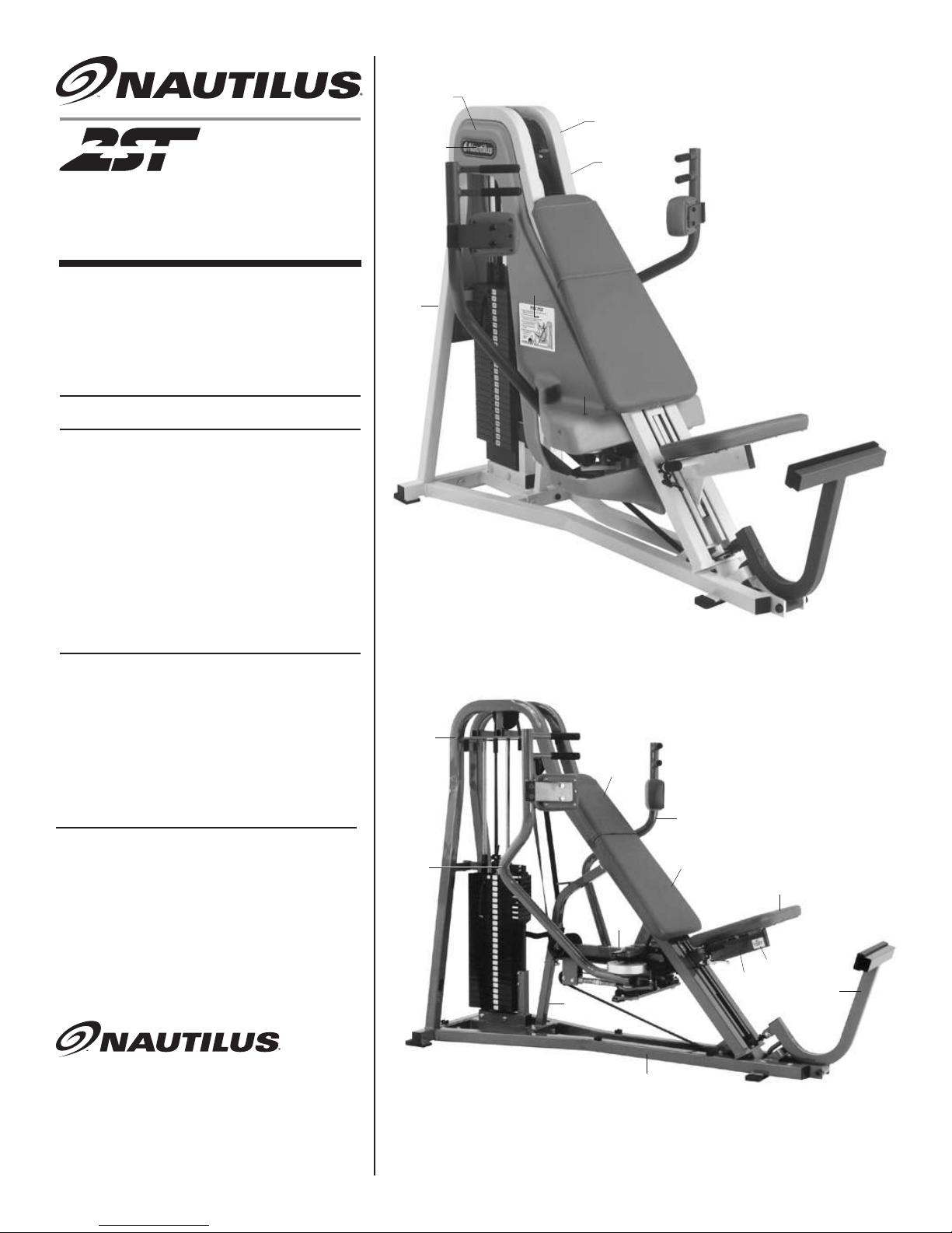
PEC FLY
OWNER'S
MANUAL
REVISED: May 19, 2006
15,22
16,23
157,159A
28
30
17,24
29
33
SERIAL NO.'S
______________
through
______________
Contents
Parts Manual
FRAME & PAD ASSEMBLY
1
WORKBOX TO FRAME ASSEMBLY
2
WORKBOX & MOVEMENT ARM ASSEMBLY
3
SEAT & FOOT LEVER ASSEMBLY
4
BELT & PULLEY ASSEMBLY
5
WEIGHT STACK ASSEMBLY
6
WEIGHT STACK ASSEMBLY
7
PARTS LIST
8
PARTS LIST
9
Maintenance Manual
Follows page 9
See last pages of this manual for 2ST Strength
Circuit Exercise Order Diagram and 2ST Floor
Plan Kit.
33
1
161
5
6
2
3
160
164
158
13
11
PARTS AND SERVICE
709 Powerhouse Road
Independence, Virginia 24348
800-235-2233
Fax: 276-773-2298
14
19-4932
Page 2
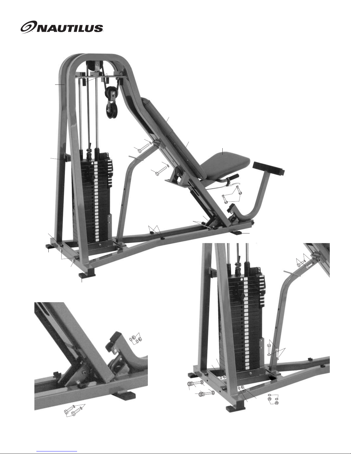
FRAME & PAD ASSEMBLY
19,26
19,
26
161
19,26
20
99
21
20
99
162
163
162
20
163
21
160
20
21
164
163
162
99
80
9
70
80
70
80
76
170
67
83
80
76
80
67
80
80
76
76
1
Page 3
WORKBOX TO FRAME
ASSEMBLY
19
19
70
99
96
99
96
48
170
71
83
81
81
81
4
96
76
141
142
76
2
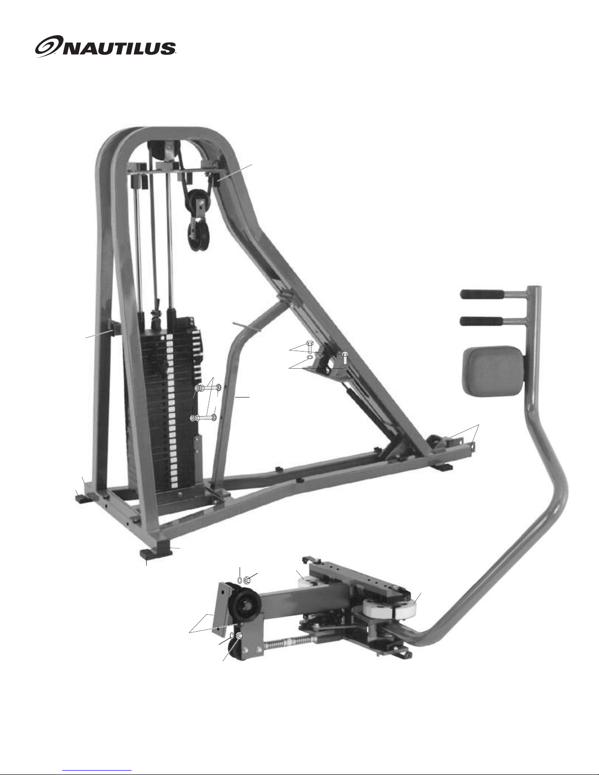
Page 4
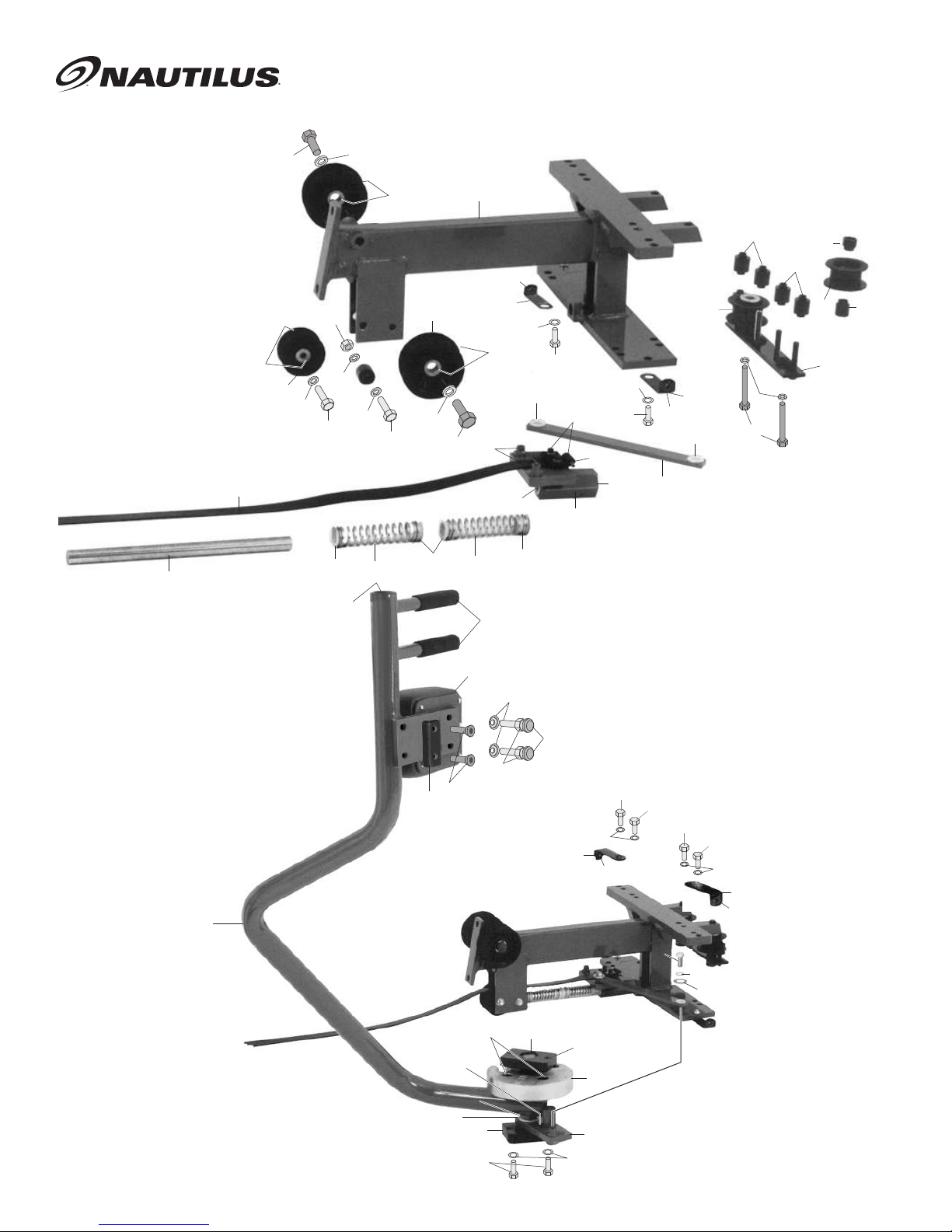
WORKBOX & MOVEMENT
ASSEMBLY
38
46
126
66
54
61
123
62
119
118
129
123
139
122
128
118
47
48
62
46
129
38
128
2
116
138
47
125
32
129
129
119
135
116
40
48
61
119
116
48
129
9
125
32
135
127
46
39
48
61
55
55
4
167
163
170
165
134
140
125
5
133
143
135
137
124
143
130
81
136
142
8
32
81
130
131
116
131
121
120
130
81
125
32
REV. 01-15-99
3
Page 5
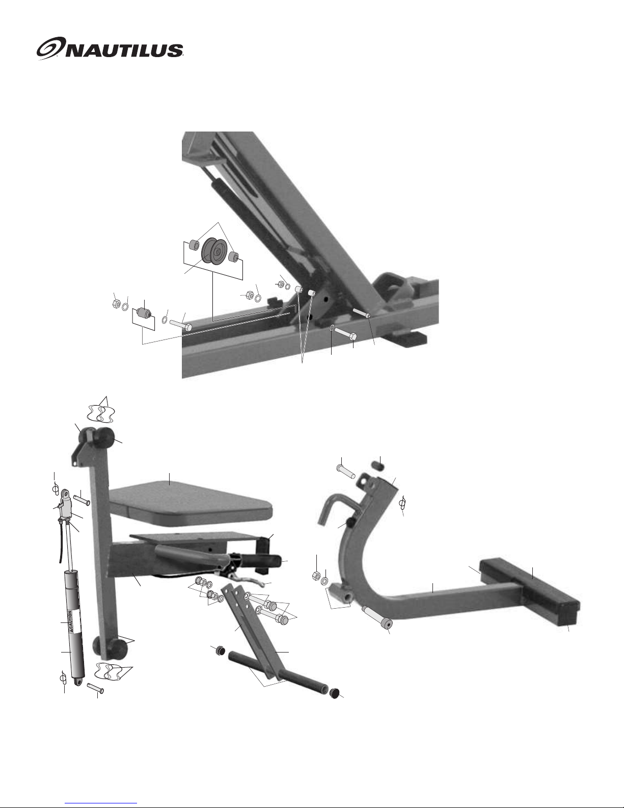
SEAT & FOOT LEVER
ASSEMBLY
50
90
104
89
100
155
88
SEAT
HIGH
74
91
154
41
44
155
48
13
155
154
44
164
61
144
36
146
148
151
152
45
46
82
78
98
85
148
43
93
112
107
94
108
145
115
144
2WPF,2WPFS
52
34
72
60
110
106
53
11
111
109
111
89
88
149
151
4
Page 6

BELT & PULLEY
ASSEMBLY
48
10
63
38
46
49
64
40
57
62
40
57
42
57
107
107
46
63
46
12
46
65
37
58
59
141
61
142
62
61
REVISION 2
56
40
59
40
52
9
58
61
60
57
42
5
Page 7

24 WEIGHT STACK
STANDARD.............
REF #....PART # .....200 lb. WEIGHT STACK (20-250)
A............01-0010.....BOLT HH2 7/16-14 X 4 1/2 BLACK
B............02-9190.....1/4-20 X 3/4 TORX HD TYPE "F" SCREW BLACK
C............03-1045.....NUT NTE 7/16 BLACK
D............04-5070.....RUBBER WEIGHT STACK WASHER
E............05-4020.....BOTTOM WEIGHT BUSHING
F............05-4055.....TOP WEIGHT BUSHING
G............06-2005.....CHAIN LINK #100 CONNECTING LINK
H............06-7064.....COIL SUPER 6"
I.............06-8150.....1 1/4 EXTERNAL SNAP RING
J.............06-8254.....SNAP RING 1"
K............07-4000.....NYLINER PLASTIC BUSHING
L............07-8296.....PIN WEIGHT SELECTOR W/MAGNET 4" LENGTH
M...........07-9268.....TOP WEIGHT SLEEVE
N............09-3066.....HOLE PLUG 1 1/4 DIA WHITE
O............09-6135.....BELT ROLLER
P............12-1024.....DECAL WARNING 3"
Q............12-1282.....WEIGHT STACK DECAL 20-310 lbs/kgs
R............17-2204.....1 X 4 X 9.330 TOP WEIGHT STEEL, 10 lbs.
S............17-2206.....1 X 4 X 9.330 SECOND WEIGHT STEEL, 10 lbs.
T............17-2203.....1 X 4 X 9.330 BOTTOM WEIGHT STEEL, 10 lbs
U............17-2203.....1 X 4 X 9.330 BOTTOM WEIGHT STEEL, 10 lbs
V............17-4115.....WEIGHT STACK PIN 24 HOLE
W...........BSF509.....WEIGHT STACK STAND 8"
X............07-9269.....3" WEIGHT STACK SPACER
Y............09-2060.....1 1/2 X 3" HOLE PLUG
WOMEN'S/MEDICAL
REF #....PART #......130 lb. WEIGHT STACK (10-200)
A............01-0010.....BOLT HH2 7/16-14 X 4 1/2 BLACK
B............02-9190.....1/4-20 X 3/4 TORX HD TYPE "F" SCREW BLACK
C............03-1045.....NUT NTE 7/16 BLACK
D............04-5070.....RUBBER WEIGHT STACK WASHER
E............05-4020.....BOTTOM WEIGHT BUSHING
F............05-4055.....TOP WEIGHT BUSHING
G............06-2005.....CHAIN LINK #100 CONNECTING LINK
H............06-7064.....COIL SUPER 6"
I.............06-8150.....1 1/4 EXTERNAL SNAP RING
J.............06-8254.....SNAP RING 1"
K............07-4000.....NYLINER PLASTIC BUSHING
L............07-8296.....PIN WEIGHT SELECTOR W/MAGNET 4" LENGTH
M...........07-9268.....TOP WEIGHT SLEEVE
N............09-3066.....HOLE PLUG 1 1/4 DIA WHITE
O............09-6135.....BELT ROLLER
P............12-1024.....DECAL WARNING 3"
Q............12-1281.....WEIGHT STACK DECAL (WOMEN'S) 10-260 lbs/kgs
R............17-2210.....1 X 4 X 9.330 TOP WEIGHT ALUM., 3.5 lbs.
S............17-2212.....1 X 4 X 9.330 SECOND WEIGHT ALUM., 3.5 lbs.
T............17-2211.....1 X 4 X 9.330 BOTTOM WEIGHT ALUM., 3.5 lbs.
U............17-2203.....1 X 4 X 9.330 BOTTOM WEIGHT STEEL, 10 lbs.
V............17-4115.....WEIGHT STACK PIN 24 HOLE
W...........BSF509.....WEIGHT STACK STAND 8"
X............07-9269.....3" WEIGHT STACK SPACER
Y............09-2060.....1 1/2 X 3" HOLE PLUG
Z............12-1048.....WEIGHT STACK DECAL (MEDICAL) #1-30
SUPER STACK
REF#.....PART #......290 lb. WEIGHT STACK (20-365)
A............01-0010.....BOLT HH2 7/16-14 X 4 1/2 BLACK
B............02-9190.....1/4-20 X 3/4 TORX HD TYPE "F" SCREW BLACK
C............03-1045.....NUT NTE 7/16 BLACK
D............04-5070.....RUBBER WEIGHT STACK WASHER
E............05-4020.....BOTTOM WEIGHT BUSHING
F............05-4055.....TOP WEIGHT BUSHING
G............06-2005.....CHAIN LINK #100 CONNECTING LINK
H............06-7064.....COIL SUPER 6"
I.............06-8150.....1 1/4 EXTERNAL SNAP RING
J.............06-8254.....SNAP RING 1"
K............07-4000.....NYLINER PLASTIC BUSHING
L............07-8297.....PIN WEIGHT SELECTOR W/MAGNET 7" LENGTH
M...........07-9268.....TOP WEIGHT SLEEVE
N............09-3066.....HOLE PLUG 1 1/4 DIA WHITE
O............09-6135.....BELT ROLLER
P............12-1028.....DECAL WARNING 6"
Q............12-1283.....WEIGHT STACK DECAL 20-455 lbs/kgs
R............17-2204.....1 X 4 X 9.330 TOP WEIGHT STEEL, 10 lbs.
S............17-2207.....1 X 6 X 9.330 SECOND WEIGHT STEEL, 15 lbs.
T............17-2205.....1 X 6 X 9.330 BOTTOM WEIGHT STEEL, 15 lbs.
U............17-2205.....1 X 6 X 9.330 BOTTOM WEIGHT STEEL, 15 lbs.
V............17-4115.....WEIGHT STACK PIN 24 HOLE
W...........BSF509.....WEIGHT STACK STAND 8"
X............07-9269.....3" WEIGHT STACK SPACER
Y............09-2060.....1 1/2 X 3" HOLE PLUG
USE CAUTION
WHEN WORKING
WITH WEIGHT
STACK !
J
J
M
F
O
M
F
G
K
C
R
E
A
E
V
S
B
H
T
L
Q,Z
U
D
01-13-99
6
Page 8

MINI 24 ADD-ON WEIGHT KIT
PEC FLY
REF #...PART #........DESCRIPTION
AA........01-1546.......3/8-16 X 3/4 HEX BOLT BLACK
BB........01-1151........3/8-16 X 2-3/4 HEX BOLT BLACK
CC........01-4035 .......1/4 X 1-1/4 WIZ BOLT BLACK
DD........02-9190 .......1/4-20 X 3/4 TORX HD TYPE "F" SCREW BLACK
EE........02-9250.......3/8 X 2-1/4 HEX BOLT BLACK
FF ........03-1035 .......3/8 WIZ NUT BLACK ZINC
GG.......03-4290 .......1/4 WIZ NUT BLACK ZINC
HH........04-5207 .......1/2 SAE FLAT WASHER BLACK
II...........04-5225.......1/4 LOCK WASHERS
JJ.........04-5214 .......1/2 LOCK WASHERS BLACK
KK........06-7062........450 OD 5" SUPER COIL
LL.........07-5083.......MINI WEIGHT BRACKET LR-PF
MM.......07-8045.......ADD ON WEIGHT SELECTOR PIN & KNOB
NN........07-9245 .......MOLDED WEIGHT STAND INSERT
OO.......07-9250 .......MOLDED ADD-ON-WEIGHT BASE
PP........07-9255.......MOLDED ADD-ON-WEIGHT LINK
QQ ......07-9292 .......STANDARD MINI WT. STACK PIN
RR........09-3072 .......HOLE PLUG 3/8" BLACK
SS........12-1117........ADD ON WEIGHT DECAL LBS/KGS
TT ........17-5998 .......CAST ADD-ON SECOND PLATE
UU........17-5999 .......CAST ONE POUND WEIGHT
VV........17-6015.......RECTANGULAR WEIGHT BUSHING
WW......BSF514........MINI-WEIGHT STAND LR-PF
XX........08-1450.......3/4 X 2 PLASTIC SPACER
YY........07-6020.......3/4" LOCK COLLAR
XX
YY
PP
AAA
I
CC
GG
TT
VV
KK
DD
MM
UU
NO WEIGHT STAND:
2LR, 2PF
AAA......07-9292 .......SHORT MINI WEIGHT STACK PIN
BBB......BSF514........SHORT MINI WEIGHT STAND
USE CAUTION
WHEN WORKING
WITH WEIGHT
STACK !
BBB
BB
NN
OO
BB
LL
SS
HH
AA
HH
AA
HH
HH
FF
01-13-99
EE
HH
HH
FF
7
Page 9

2ST PEC FLY
REV. 05-19-06
E.L. CODES:.............
2PFS....FULLY SHIELDED PEC FLY
2WPFS FULLY SHIELDED WOMENS' PEC FLY
2MPFS FULLY SHIELDED MEDICAL PEC FLY
2PF......PARTIAL SHIELDED PEC FLY
2WPF ..PARTIAL SHIELDED WOMENS' PEC FLY
2SPF....PARTIAL SHIELDED SUPER PEC FLY
REF# ...PART# ........DESCRIPTION
.............
E.L. CODE:..2PFS,2WPFS, 2MPFS, 2PF, 2WPF, 2SPF.............
WL16...........WELDMENT KIT PEC-FLY
1...........BF508..........BACK FRAME ASSEMBLY
2...........WB512.........WORKBOX
3...........CM535.........DIAGONAL WORKBOX BRACE
4...........CM538.........WORKBOX PULLEY IDLER BRACKET
5...........MA547.........LEFT CHEST MOVEMENT ARM
6...........MA548.........RIGHT CHEST MOVEMENT ARM
7...........LK521..........LEFT DRIVE MA LINK
8...........LK522..........RIGHT DRIVE MA LINK
9...........LK523..........LINKAGE/SPRING BELT ANCHOR
10.........LK530..........BELT KEEPER FOR PEC-FLY
11.........FL504..........FOOT LEVER ASSEMBLY
12.........IB400...........STND 2/3 INCH PULEY COMBO IDLER BRACKET
13.........SE505..........PEC FLY SEAT
14.........BSF502........PEC FLY BASEFRAME.............
.............
E.L. CODE:..2PF, 2WPF, 2SPF.............
SH42............SHIELD KIT 2PF (PARTIAL)
15.........14-2052.......2PF LEFT SIDE (PARTIAL)
16.........14-2054.......2PF RIGHT SIDE (PARTIAL)
17.........14-2075.......2PF BACK SHIELD
18.........19-1015.......2" SQ SERIES 170 DUAL LOC
19.........19-1016.......1" X 2" RECTANGLE SERIES 400 DUAL LOC.............
.............
E.L. CODE:..2PFS,2WPFS, 2MPFS.............
SH43............SHIELD KIT 2PFS (FULL)
20.........02-4134.......1/4 X 1/2 CUTTING SCREW TYPE F
21.........07-5416.......1/8 X 1 X 1/2 CHNL
22.........14-2051.......LEFT SIDE (FULL)
23.........14-2053.......RIGHT SIDE (FULL)
24.........14-2056.......BACK SIDE (FULL)
25.........19-1015.......2" SQ SERIES 170 DUAL LOC
26.........19-1016.......1" X 2" RECTANGLE SERIES 400 DUAL LOC.............
.............
E.L. CODE:..2PFS,2WPFS, 2MPFS, 2PF, 2WPF, 2SPF.............
SH41............SHIELD KIT PEC FLY
27.........12-1026.......KEEP HANDS AWAY
28 ................................................................
29.........12-1120........RED PINE TREE CLIP
30.........12-2782.......INSTRUCTION PLACARD PEC FLY
31.........19-4932.......PARTS DIAGRAM PEC FLY
32.........03-4060.......1/4-20 CLIP NUTS
33.........02-4070.......1/4 X 3/4 SHIELD SCREWS.............
.............
E.L. CODE:..2PFS,2WPFS, 2MPFS, 2PF, 2WPF, 2SPF.............
BLT16..........BELT & PULLEY KIT PEC-FLY
34.........01-0011........BOLT HH5 1/2 X 3 BLACK
35.........01-1115........BOLT HH5 3/8 X 2 1/2 BLACK
36.........01-1151........BOLT HH5 3/8 X 2 3/4 BLACK
37.........01-1510.......BOLT HH8 5/8 X 2 1/4
38.........01-2180.......BOLT HH8 5/8 X 1 1/2
39.........01-2200.......BOLT HH8 5/8 X 3 1/2
40.........01-4030.......1/4 X 1 WHIZ FLANGE SM PATTERN ZINC
40A ......03-4035 .......1/4-20 X 11/16 THREADED INSERT
41.........03-1035.......3/8 NUT BLACK
42.........03-4290.......1/4-20 WHIZ FLANGE L/N SM PATTERN ZINC
43.........03-1055.......1/2 NUT BLACK
REF# ...PART# ........DESCRIPTION
44.........04-5213.......3/8 LOC WASH BLACK
45.........04-5214.......1/2 INT LOK WASHER BLACK
46.........04-5215.......5/8 LOC WASH
47.........05-6035.......PULLEY BUSHING
48.........06-5045.......ROLLER BELT (ANTI JUMP)
49.........07-5072.......ANTI-JUMP SPACER
50.........07-5440.......5/8 ID PULLEY SPACER 7/8 DIA .627 ID .875 L
51.........07-7041.......1/4 X 2 ROLL PIN
52.........07-8028.......1/2 X 2 CLEVIS PIN
53.........07-8034.......RUE-22 RUE RING COTTER 1/2"
54.........07-8346.......PULLEY SPACER 7/8 OD X 25/64 ID X 3/4 LONG
55.........07-8363.......PULLEY IDLER SPACER 33/64 I.D. X .813
56.........07-8982.......WT. ST. BELT ANCHOR WITH 5/16 DIA HOLES
57.........07-8982.......WT. ST. BELT ANCHOR (2 HOLE)
58.........08-7063.......TEARDROP (CAM)
59.........08-7064.......TEARDROP INSERT
60.........09-6205.......FOOTLEVER PIN BELT ROLLER 3/4 OD X 1 1/4
L
61.........09-8323.......2" PULLEY
62.........09-8327.......3" PULLEY
63.........09-8330.......4" PULLEY
64.........24-6030.......KEVLAR BELT 63" LENGTH ( TO WEIGHTS)
65.........24-6030.......KEVLAR BELT 130" LENGTH (M.A.'S)
66.........24-6030.......KEVLAR BELT 67" LENGTH (FOOTPEDAL).............
.............
E.L. CODE:..2PFS,2WPFS, 2MPFS, 2PF, 2WPF, 2SPF.............
FR14............FRAME KIT PEC-FLY
67.........01-0011........1/2 X 3 HH5 BLACK
68.........02-9250.......3/8 X 2 1/4 HH5
69.........01-1258.......1/2 X 3/4 HH5
70.........01-1271.......1/2 X 1 1/4 HH5 BLACK
71.........01-1321.......1/2 X 2 1/2 HHB
72.........02-1150........SCREW AC 5/16 X 3 BLACK
73.........02-4115........1/2 X 3/4 ALLEN CAP SCREW
74.........03-5106.......NUT HEX 10MM
75.........03-1035.......3/8 NTE
76.........03-1055.......1/2 NTE
77.........03-1055.......NUT BLACK ZINC 1/2-13
78.........03-4142.......5/16 NUT BLACK
79.........04-5207.......1/2 FLAT WASHER BLACK
80.........04-5214.......1/2 LOC WASHER
81.........04-5214.......1/2 INT LOC WASHER BLACK
82.........04-3071.......5/16 LOK WASHER BLACK
83.........04-5130.......1/2" BOLT CAP WASHER
84.........04-5135.......3/8" BOLT CAP WASHER
85.........06-8000.......SEAT ADJUSTMENT HANDLE 7/8"
86.........06-8006.......SEAT ADJUSTMENT CABLE, 18"
87.........07-6021.......3/4" LOCK COLLAR
88.........07-8027.......PIN CLEVIS 5/16 X 1 3/16
89.........07-8135.......COTTER PIN #RUE-10 mfg. PIVOT POINT
90.........07-9201.......SHOCK LEVER P/N 783234
91.........07-9205.......HEAD THREAD ON CAST ALUM
92.........08-1450.......3/4 X 2 PLASTIC SPACER
93.........08-3000.......SPACER 1/2 DIA X .058 W X 1/2 LONG
94.........09-1058.......RUBBER HAND GRIP, 7/8 X 4 1/2
95.........09-2010.......1 1/4" FRAME PLUG
96.........09-2070.......2" SQ FRAME PLUG
97.........09-3063.......7/16" WHITE HOLE PLUG
98.........09-3080.......1 X 3 HOLE PLUG
99.........09-5035.......RECTANGLE FOOTPAD
100.......10-3045 ......RIGID IN COMPRESSION, 250 N #7613IL
101.......12-1001.......SEAT POSITION INDICATOR ARROW
102.......12-1009.......SEAT DECAL 1 BOTTOM -10 TOP (5/8 WIDE)
103.......12-1109........SEAT SHOCK ADJ. TAG
104.......12-1113........SHOCK WARNING DECAL
105......17-1305......GUIDE RODS 48 3/4 INCHES LENGTH
8
Page 10

REF# ...PART# ........DESCRIPTION
.............
E.L. CODE:..2PFS,2WPFS, 2MPFS, 2PF, 2WPF, 2SPF.............
FP01............FOOTPEDAL KIT PEC-FLY
106.......01-3300.......3/4 X 3 1/2 SH BOLT
107.......03-1067.......5/8 NUT BLACK
108.......04-5215.......5/8 LOK WASHER BLACK
109.......09-1157........FOOT GRIP 1/4 X 2.5 X 1 PVC CH 13 5/8 L
110.......09-2040.......1 1/2 X 2 FRAME PLUG
111.......09-2070 .......2" SQ HOLE PLUG
112.......09-4092.......MOLDED URETHANE STOP
113.......09-8053.......VINYL CAP 1.000 DIA X 1/2" L BLACK TEXTURE
114.......19-1012.......TAPE DOUBLE SIDED 1.5" WIDE 13.5" LONG
115.......45-1051.......BUSHING IGUS PLAIN LFI-1214-08.............
.............
E.L. CODE:..2PFS,2WPFS, 2MPFS, 2PF, 2WPF, 2SPF.............
WX04...........WORKBOX KIT PEC-FLY
116.......01-1546.......3/8 X 3/4 HH5 BOLT
117.......02-9210.......3/8 X 1 HH5 BOLT
118.......01-1115........3/8 X 2 1/2 HH5 BOLT BLACK
119.......03-1035.......3/8 NTE BLACK
120.......04-5206.......3/8 FLAT WASHERS
121.......04-5213.......3/8 LOC WASH
122.......04-5213.......3/8 LOC WASH BLACK
123.......04-5214.......1/2 LOC WASH
124.......05-5132.......IGUS 1 1/8 ID X 1/2 L NYLON BUSHING
125.......07-5439.......1/8 X 1 HRF WB SHIELD MOUNT
126.......07-8278.......3/4 DIA DURO ROD CONTROL ROD
127.......07-9008.......1/4 X 1 CONNECT LINK BAR
128.......10-2095.......FOOTPEDAL SPRING (FOR GUIDE ROD)
129.......45-1051.......IGUS 3/4 ID X 1/2 L BUSHING (LFI 1214-08).............
.............
E.L. CODE:..2PFS,2WPFS, 2MPFS, 2PF, 2WPF, 2SPF.............
MV06...........MOVEMENT ARM KIT PEC-FLY
130.......01-1271.......1/2 X 1 1/4 HHB
131.......01-1282.......1/2 X 1 1/2 HHB
132.......01-1560.......1/2 X 1 3/4 HH5
133.......02-4117........1/2 X 1 1/4 AC
134.......02-4123.......SCREW AFH 3/8-16 X 1/2 BLACK
135.......05-5130.......IGUS 1/2 ID X 5/8 NYLON BUSHING
136.......07-8402.......BEARING MOUNT BLOCK UPPER MA AXLE
137.......08-7039.......SPACER NYLON LINK STANDOFF
138.......09-1050.......7/8 X 8 1/2 CLOSED END GRIP
139.......09-3090.......PLUG HOLE 1.75 OD X 1.37 ID X .75 L
140.......09-5002.......URETHANE BLACK PECTORAL FLY MA BUMPER
141.......11-1380........MCH CAM LEFT
142.......11-1385........MCH CAM RIGHT
143.......45-1063.......205 PP BEARING.............
.............
E.L. CODE:..2WPFS, 2MPFS, 2WPF.............
ST21............SEAT WOMENS & MED. PF KIT
144.......04-5145.......PLASTIC BOLT CAP
145.......01-1121........3/8 X 2 HH5
146.......03-1035.......3/8 NTE
147.......04-5213.......3/8 LOC WASH
148.......04-5135.......3/8" BOLT CAP WASHER
149.......09-1106..........938 ID X 9 OPEN END GRIP
150.......09-3063.......7/16" WHITE HOLE PLUG
151.......09-3094.......1.25 OD X .75 ID X .75 L HOLE PLUG
152.......SE510..........WOMEN'S FOOTREST ASSEMBLY.............
.............
E.L. CODE:..2PFS,2WPFS, 2MPFS, 2PF, 2WPF, 2SPF.............
BR01............SEAT BEARINGS KIT 1
153.......07-5065.......BEARING FAFNIR 203 PP
154.......10-4012.......40 MM O.D. WAVE SPRING SSB-0158-S17
155......19-1235......NYLON SEAT ROLLERS
REF# ...PART# ........DESCRIPTION
.............
E.L. CODE:..2PFS,2WPFS, 2MPFS, 2PF, 2WPF, 2SPF.............
IN01.............INSPECTION KIT
156.......12-1080.......INSPECTION STICKER DECAL
157.......12-1088.......DECAL NAUTILUS NAMEPLATE 2 1/2 x 9 1/4 long
158.......19-1291.......DECAL SERIAL # BAR CODE
159.......40-7167.......BAG 50 X 46 X 86 X .002 THICK
.............
E.L. CODE:..2WPFS, 2WPF.............
IN03.............INSPECTION KIT
159A ....12-1175........NAUTILUS WOMEN'S NAMEPLATE 2 1/2 x 9 1/4.............
.............
E.L. CODE:..2PFS,2WPFS, 2MPFS, 2PF, 2WPF, 2SPF.............
UPH09.........PEC-FLY UPHOLSTERY KIT
160.......UP8432........SEAT BACK PAD
161.......UP720..........SLIPCOVER
162.......01-1551.......BOLT HH5 3/8 x 3 1/4 BLACK
163.......04-5213.......WASHER INT LOK 3/8 BLACK
164.......UP8015........SEAT BOTTOM
165.......02-9220.......BOLT HH5 3/8 X 1 1/4 BLACK
166.......04-5213.......WASHER INT LOK 3/8 BLACK
167.......UP8350........WRIST PAD
168.......02-9220.......BOLT HH5 3/8 X 1 1/4 BLACK
169.......04-5135.......3/8" BOLT CAP WASHER
170.......04-5145.......PLASTIC BOLT CAP.............
.............
E.L. CODE:..2PF, 2WPF, 2SPF
171.......09-3067.......1/4" WHITE HOLE PLUG
9
Page 11

Kevlar™ Belt Adjustment
TWO
QUARTERS
FOR SHIMS
TOP
WEIGHT
STACK
WEIGHT-PIN
BOLTS
KG.
LB.
20
9
KG.
LB.
30
14
KG.
LB.
40
18
KG.
LB.
50
23
KG.
LB.
60
27
KG.
LB.
70
32
LB.
80
TM
®
Instructions
Belts require tightening when a lack of resistance and
uneven feel is noticed at the beginning of an exercise. USE
CAUTION AROUND THE WEIGHT STACK WHEN
TIGHTENING KEVLAR™ BELTS.
To adjust belt:
1. Remove the Shielding.
2. Remove the Tethered Weight-Pin from weight stack hole.
See Figure 3.
3. Lift top weight using the appropriate lifting mechanism
- in most cases the moving arms for exercising.
4. While top weight is suspended, insert a shim between
the first and second weight (two quarters will suffice).
5. Release top weight so the first stack is resting on the
shim.
6. Loosen the two bolts at the end of the belt and pull
through excess belting until tight.
7. Tighten belt bolts and lift top weight to remove the shim.
8. Lower the mechanism to rest on the weight stack.
9. If belt is still loose, repeat this procedure until there is
no looseness at the beginning of an exercise.
10. If you experience difficulties in tightening the belts,
please contact your Nautilus service professional or call
1-800-NAUTILUS (1-800-235-2233), Parts & Service
Department, for assistance.
Figure 3
Store indoors only. Do not subject
machine to high humidity or damp
WARNING
conditions.
Warranty Information
Nautilus® Variable Resistance Warranty Limited
Warranty Terms & General Specifications
Nautilus warrants only to the original purchaser
that Nautilus® exercise equipment from the
manufacturer is free from defects in material and
workmanship under normal use and service. Our
obligation under this warranty shall be limited to the
repair or exchange at our plant (a) of any part or parts
of the structural frame, moving weldments or weight
stacks which may thus prove defective under normal
use and service for the lifetime of the product from
delivery to the original purchaser; (b) of any moving
part or parts not otherwise disclosed within this
warranty which thus may prove defective under
normal use and service within one (1) year from
delivery to the original purchaser; and (c) of any
upholstery, pads, grips or tethered weight pin
connectors which thus may prove defective under
normal use and service within 120 days from delivery
to the original purchaser. This warranty only applies
to those parts that our own examination discloses to
our satisfaction to be thus defective.
This warranty is expressly in lieu of all other
warranties, express or implied, including the
warranties of merchantability and fitness for use and
of all other obligations or liabilities on our part, and
we neither assume nor authorize any other person to
assume for us any other liability in connection with
the sale of this NAUTILUS® exercise equipment. This
warranty shall not apply to this NAUTILUS® exercise
equipment or to any part thereof which has been
subject to accident, negligence, alteration, abuse, misuse,
or a lack of maintenance in accordance with our
recommended maintenance instructions. We make no
warranty whatsoever in respect to accessories or parts
not manufactured by us and disclaim all warranties,
express or implied, as to such accessories and parts. The
term “original purchaser”, as used in this warranty, shall
be deemed to mean that person or entity for whom this
NAUTILUS® exercise equipment is originally installed.
This warranty shall apply only within the boundaries of
the continental United States.
NAUTILUS® shall not be liable for any loss or
damage, including incidental or consequential damages
resulting directly or indirectly from the use or loss of use
of our NAUTILUS® exercise equipment. Without
limiting the generality of the foregoing, this exclusion
from liability embraces the purchaser’s expenses for
downtime or for making up downtime, damages for
which the purchaser may be liable to other persons,
damages to property, and injury to or death of any
persons. We neither assume not authorize any person to
assume for us any liability in connection with sale or use
of our equipment. There are no oral agreements or
warranties collateral to or affecting this agreement.
4
Page 12

TM
®
Contents
Maintenance
INSTRUCTIONS
For Variable Resistance Strength Training Equipment
Getting maximum results from Nautilus
machines depends on proper maintenance
of equipment.
Welcome
®
Welcome ...........................................................1
Parts & Service ..................................................2
Safety/Before Exercising...................................2
Maintenance Schedule...................................2
General Maintenance.....................................2
Cleaning............................................................3
Lubrication.........................................................3
Hydraulic Unit Adjustment ...............................3
Kevlar Belt Adjustment Instructions.................4
Warranty Information........................................4
Parts & Services
Regular and scheduled maintenance will prolong the life
of your Nautilus equipment. Should you have to replace
parts, use only genuine Nautilus parts. The Nautilus
Customer Service Team invites you to call in your order
for replacement parts. They’re never too busy to discuss
or offer a tip on your maintenance tasks.
Nautilus machines -- the culmination of years of research
and refinement -- are made from the highest quality
materials, under exacting conditions. The quality control
tag attached to each machine before shipping ensures that
each unit has been thoroughly inspected to meet Nautilus'
strict requirements.
Should you, the owner of a Nautilus machine, need to
replace any parts because of normal wear and tear, or should
your machine ever need maintenance, Nautilus invites you
to call our Virginia Headquarters office for information on
parts and service.
Nautilus has available: detailed isometric drawings on
the website @ www.nautilus.com for each machine
manufactured, genuine Nautilus Upholstery Pads,
Naugahyde® Spray Cleaner/Conditioner recommended for
Nautilus upholstery pads and TFL #50 Wet Lubricant
recommended for the care of the guide rods of Nautilus
selectorized resistance machines.
Nautilus’ concern for the customer does not end with
the purchase of equipment. Your comments are always
welcomed. In the unlikely event that a problem occurs, call
us toll free:
Congratulations on choosing Nautilus® Variable
Resistance strength training equipment. The addition
of several exciting new features to the Nautilus® line,
as outlined in these instructions, ensures that your
equipment will operate with little scheduled
maintenance. We know this is important to you and
your customers, so please take a few minutes to read
the following instructions for keeping your Nautilus®
equipment in the best working condition.
Nautilus
TM
Customer Service
1-800-235-2233
Fax: 276-773-2298
1
Page 13

Before Exercising
Safety
1. Supervision is necessary when the machine is
used by or near children, invalids, or disabled
persons.
2. Follow the instructions for specific exercises on
each machine
3. Get in and out of the equipment carefully.
4. Never operate the machine without shields in
place.
5. Use only Nautilus selector pins in weight stack.
Never drop or insert any other object into
machine opening.
6. Use this machine only as intended or described
in this manual.
7. Do not operate equipment with loose or damaged
parts. If machine fails to operate correctly, do not
attempt to repair. Notify authorized personnel of
the problems.
8. Keep hands and feet clear of weights and other
moving parts when in use. Keep hands and feet
only on the hand grips and foot pads provided.
9. Failure to comply with these instructions may
result in personal injury.
To guard against injury, all equipment users
should follow these instructions.
■ Check with your physician and get approval
before beginning a training routine.
■ Become familiar with the equipment before
beginning a training routine.
■ Always warm-up before and cool down after
exercising.
■ Move slowly during each exercise. Do not jerk
or "throw" the weight.
■ Breathe freely. Do not hold your breath while
lifting or lowering weight.
■ Hold movement arms and handles firmly, do
not squeeze or grip tightly.
■ Structure each workout to exercise the largest
muscles first. Suggested routines are found in
the Nautilus Total Fitness Program.
■ Experiment to find the exact weight you need
for each exercise. Select a resistance that allows
you to perform eight to twelve slow repetitions.
Take two seconds to lift the weight. Pause briefly,
and take four seconds to lower the weight.
Stop exercising immediately if you experience a sharp
nerve or joint pain, and seek medical advice.
Maintenance Schedule
EVERY 6
DAILY WEEKLY MONTHLY MONTHS
General Maintenance
Check Safety & Warning Decals ✿✿✿✿✿✿✿✿✿✿✿✿✿■
Inspect Belts & Cables ✿✿✿✿✿✿✿✿✿✿✿✿✿✿✿✿✿■
Spot Check Belt ✿✿✿✿✿✿✿✿✿✿✿✿✿✿✿✿✿✿✿✿✿✿✿✿✿✿✿✿✿✿✿✿✿✿✿✿✿■
Spot Check Nuts and Bolts ✿✿✿✿✿✿✿✿✿✿✿✿✿✿✿✿✿✿✿✿✿✿✿✿✿✿✿✿✿✿✿✿■
Spot Check All Pegs and Stops _______________________________________________________■
Examine Rotation Points _________________________________________________________________________■
Cleaning
Clean Upholstery _____________________________________■
Use Nautilus Disinfectant Cleaner.
Clean Surface Area _________________________________________________■
Remove Dust___________________________________________________________________________________■
Lubrication
Lubricate and Clean Guide Rods Using TFL 50___________________________■
Do not lubricate hydraulic cylinders.
2
Page 14

3. SHIELD REMOVAL
HANDLE
NUT
ADJUSTMENT
BARREL
HANDLE HOUSING
HANDLE
LEVER
1/4" free play
Detergent/
Disinfectant-Odor
Counteractant
Detergente/
Desinfectante
y Neutralizante
de Olores
Keep out of Reach of
Children • For Industrial
Use Only
HEALTH
FIRE
REACTIVE
Nautilus® 2ST machines are equipped with quickrelease shield fasteners. To remove Quick-Release
shielding, gently pull shielding away from the frame.
Use a proper screwdriver to remove front shielding,
which is attached to the frame with screws.
Cleaning
1. UPHOLSTERY CLEANING AND PROTECTION
A. Keep pads free of perspiration at all times.
B. Clean and disinfect upholstery at the end of each
day, especially areas where perspiration and scalp
oil collect.
C. Clean all outside surfaces with non-abrasive, non-
chlorinated household cleaners. Nautilus
Disinfectant Cleaner is an effective upholstery care
product.
2. CLEANING AND CARE OF PAINTED
SURFACES
A. Wipe painted surfaces with a
damp cloth and car wax.
B. Let dry and buff with a dry
cloth.
3. CLEANING AND CARE OF ABS PLASTIC
SHIELDING
PART
NUMBER
19-1175
A. Clean with non-abrasive, non-
chlorinated household cleaners.
B. Vacuum or wipe dust from
recessed areas and surfaces
QUI K FILL A-
33
Detergent/Disinfectant Odor Counteractant
Lubrication
MOVING PARTS
A. To clean and lubricate guide rods, apply TFL#50
Wet Lubricant to a clean cloth then use to wipe
rods.
Hydraulic Unit Adjustment
Note: The hydraulic unit only needs adjustment if the
seat will not stay in position.
1. Remove CLEVIS and COTTER PINS. Remove
CIRCULAR COTTER PINS by lifting up the wire that crosses
over straight end of pin, see Figure 1. Save all PINS.
2. Use a flat blade screwdriver to gently unsnap CABLE
from LEVER MECHANISM. Be careful not to break cable
fitting.
3. Remove hydraulic unit from machine, loosen NUT by
backing it down ROD. Hold LEVER MECHANISM and twist
SHAFT until there is free play in LEVER, as shown by "B" in
Figure 1.
4. Hold LEVER MECHANISM and twist SHAFT (as shown
by "C" in Figure 3) until LEVER free play is gone, then back
off 1/8 turn. Tighten NUT against LEVER MECHANISM. The
NUT MUST BE PROPERLY TIGHTENED to keep hydraulic
unit in adjustment.
5. Twist SHAFT slightly to realign the top and bottom
clevis pin holes.
6. Use pliers to snap and lock the CABLE on to the LEVER
MECHANISM.
7. Reposition the hydraulic unit on machine and insert
CLEVIS and COTTER PINS. The circular COTTER PINS can
be pushed into holes.
8. The HANDLE NUT should be tight against the
HANDLE HOUSING, see Figure 2. The HANDLE LEVER
should touch the GRIP when squeezed. If it does not touch,
adjust as follows:
a. Loosen the HANDLE NUT by turning counter
clockwise.
b. Turn the ADJUSTMENT BARREL clockwise until the
HANDLE LEVER has approximately 1/4" free play.
c. Tighten the HANDLE NUT against the HANDLE
HOUSING.
LEVER
MECHANISM
LEVER
A
NUT
WARNING
STOCK NO.
RG 60127
Do not lubricate
MINI WEIGHTS.
May cause damage
and VOID
WARRANTY.
Do not place equipment in direct sunlight as ultra violet
rays can damage shields and upholstery.
■ Cleans/Lubricates/Protects
■ Homogenized/No Kerosene/No Wax
■ Non-Toxic/Environmentally Safe
■ Nettote/Lubrifie/Protege
■ Produit Homogénéisé/Formule
D'avant-Garde/Sans Cire
■ Non-Toxique/Sans Effet Sur
E'environnement
NET WT. 10 OZ. (283.5g)
DANGER! EXTREMELY FLAMMABLE. HARMFUL OR FATAL IF SWALLOWED.
CONTENTS UNDER PRESSURE. SEEBACK PANEL.
DANGER! EXTREMEMENT INFLAMMABLE.
CONTENU SOUS PRESSION. VOIR ETIQUETT AL'ENDOS.
PART
NUMBER
19-1160
*TFL 50
Wet
Lubricant
Recommended
for Nautilus
Machines.
3
CABLE
B
ROD. SEAL DAMAGE WILL OCCUR.
HIGH PRESSURE : DO NOT LUBRICATE
EYE AND INJECTION HAZARD EXISTS.
CLEVIS
PIN
CIRCULAR COTTER PIN
or COTTER PIN
Figure 1
ROD. SEAL DAMAGE WILL OCCUR.
HIGH PRESSURE : DO NOT LUBRICATE
EYE AND INJECTION HAZARD EXISTS.
SHAFT
Figure 2
C
ROD. SEAL DAMAGE WILL OCCUR.
HIGH PRESSURE : DO NOT LUBRICATE
EYE AND INJECTION HAZARD EXISTS.
HIGH PRESSURE : DO NOT LUBRICATE
ROD. SEAL DAMAGE WILL OCCUR.
EYE AND INJECTION HAZARD EXISTS.
 Loading...