

Narex Vhu 2 1/8, Vhu 4 7/8"", Vhu 3 1/8"", Vhu, Vhu 6 Instruction Manual
Instruction Manual
Moskevska 63
No.: 2420304
Vhu
Producer:
Vhu
Universal Boring Heads
Vhu 2
1/8”, 3 1/8”, 4 7/8”, 6 ¼ ”
101 00 Praha 10 – Vrsovice
Czech Republic
Phone: +420 246 002 249
Fax: +420 246 002 335
e-mail: sales@narexmte.cz
www.narexmte.cz
OPERATING INSTRUCTIONS
Vhu 21/8”, 31/8”, Vhu 47/8” and Vhu 6 ¼ ” Universal Boring Heads.
Utilisation:
The Vhu 21/8”, 31/8”,Vhu 47/8” and Vhu 61/4” universal boring heads can be utilised for boring,
surfacing of front and rear facings, turning of external diameters, machining of external and internal
recesses and cutting threads. The Vhu 6 ¼ ” is same as Vhu 4 7/8” but slide here are with 5 holes
(not with 3 holes as for Vhu 4 7/8”).
By a combination of the automatic transverse feed motion of the tool slide with the motion of the
machine spindle it is possible to bore tapered holes, turn external tapers and cut tapered threads.
The taper angle depends in this case on the feed motion of the machine.
The universal boring heads widen considerably the machining possibilities of horizontal boring
machines, radial drilling machines and coordinate boring machines etc.
Examples of application:
No. of Operation Example
operation
1. Hole boring Fig. No. 1
2. Surfacing on small diameter front facing Fig. No. 2
3. Surfacing on large diameter from facing Fig. No. 3
4. Recessing in bore Fig. No. 4
5. Recessing on surface Fig. No. 5
6. External turning Fig. No. 6
7. Recessing of long shoulder Fig. No. 7
8. Taper boring Fig. No. 8
9. Surfacing on rear facing Fig. No. 9
10. Thread cutting Fig. No. 10
2
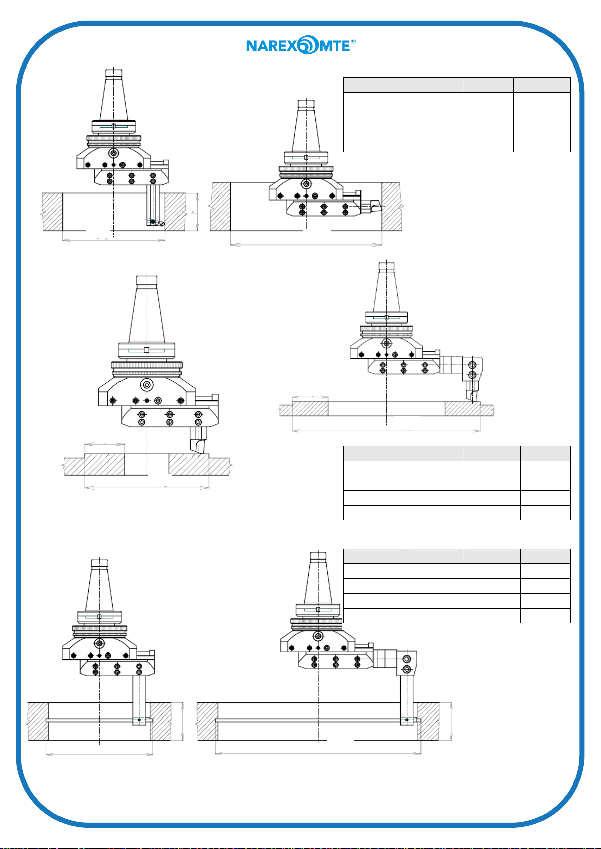
Fig. 1 – Hole boring
Fig. 1 Ø d max. h max. Ø D max.
Vhu 2.1/8" 6 1/4" 4 1/4" 9"
Vhu 3.1/8" 8" 4 1/4" 11"
Vhu 4.7/8" 11" 7 1/4" 15"
Vhu 6.1/4" 13“ 7 1/4" 18“
Ød
Fig. 2 – Surfacing on
small diameter front
facing
a
Ød
ØD
Fig. 3 Surfacing on
larger diameter front
facing
a
ØD
Fig. 2 & 3 Ø d max. Ø D max. a max.
Vhu 2.1/8" 5 1/2" 13" 2 1/8"
Vhu 3.1/8" 7" 15" 3 1/8"
Vhu 4.7/8" 9 3/4" 24" 4 7/8"
Vhu 6.1/4" 11 3/4“ 27“ 6 1/4"
Fig. 4 Recessing in bore
h
Ød
fig. 4 Ø d max. Ø D max. h max.
Vhu 2.1/8" 6 1/4" 13 3/4" 4"
Vhu 3.1/8" 8" 15 3/4" 4"
Vhu 4.7/8" 11" 25" 6 1/2"
Vhu 6.1/4" 13“ 28“ 6 1/2"
h
ØD
3
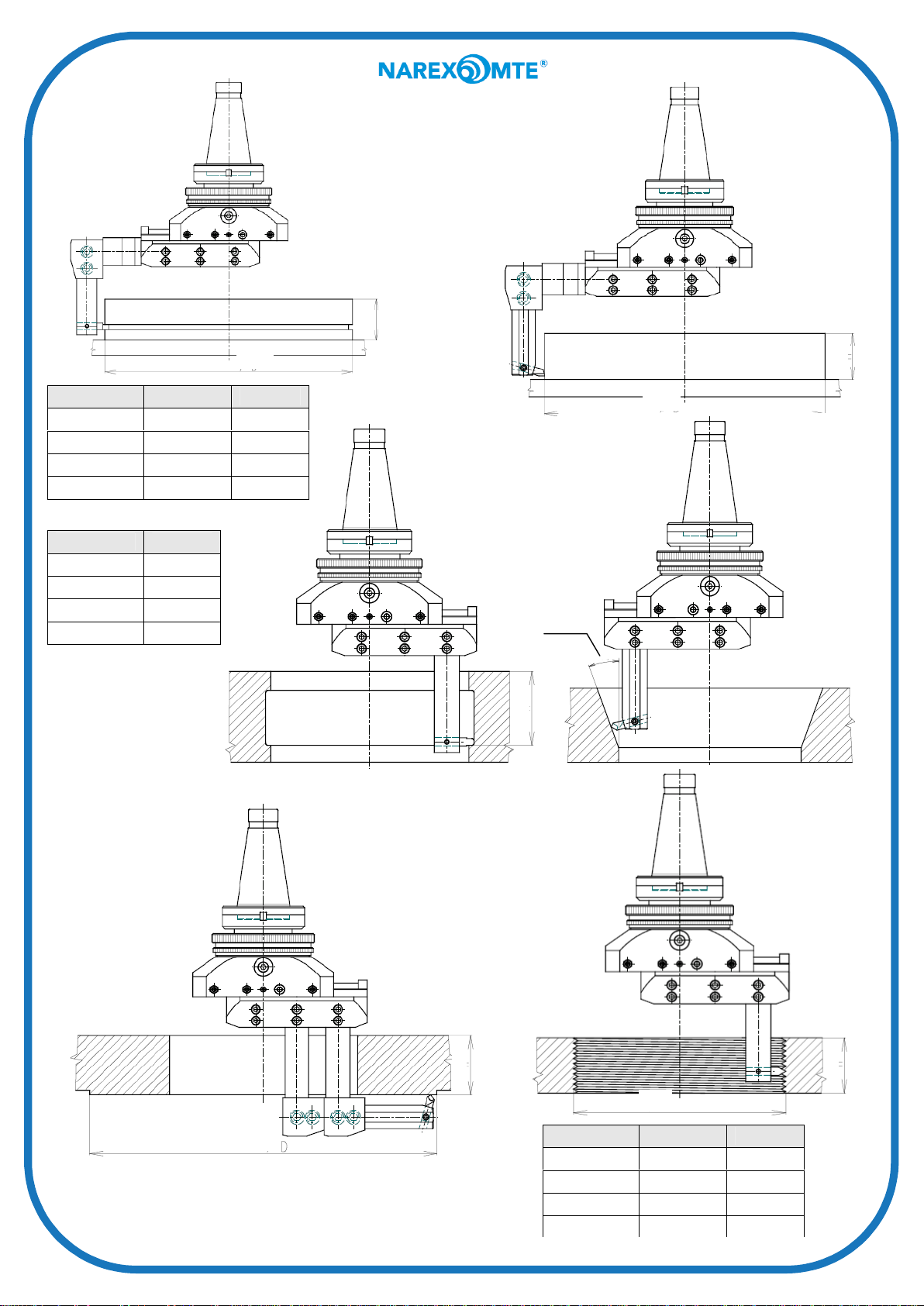
Fig.5 Recessing
on surface
Fig. 6 External
turning
h
ØD
Fig. 5 & 6 Ø D max. h max.
Vhu 2.1/8" 10 3/4" 4"
Vhu 3.1/8" 12 3/4" 4"
Vhu 4.7/8" 20 1/2" 6 1/2"
Vhu 6.1/4" 23 1/2“ 6 1/2"
Fig. 7 h max.
Vhu 2.1/8" 4"
Vhu 3.1/8" 4"
Vhu 4.7/8" 6 1/2"
Vhu 6.1/4" 6 1/2"
Fig. 7
Recessing of
long shoulder
h
ØD
Fig. 8 Taper boring
α/2 = 5º - 85º
α/2
h
ØD
Fig. 9
Surfacing on
rear facing
Fig. 10 Thread cutting
h
4
h
ØD
Fig. 5 & 6 Ø D max. h max.
Vhu 2.1/8" 12 1/2" 3 1/2"
Vhu 3.1/8" 13 1/2" 3 1/2"
Vhu 4.7/8" 21 1/2" 4"
Vhu 6.1/4" 24“ 4"

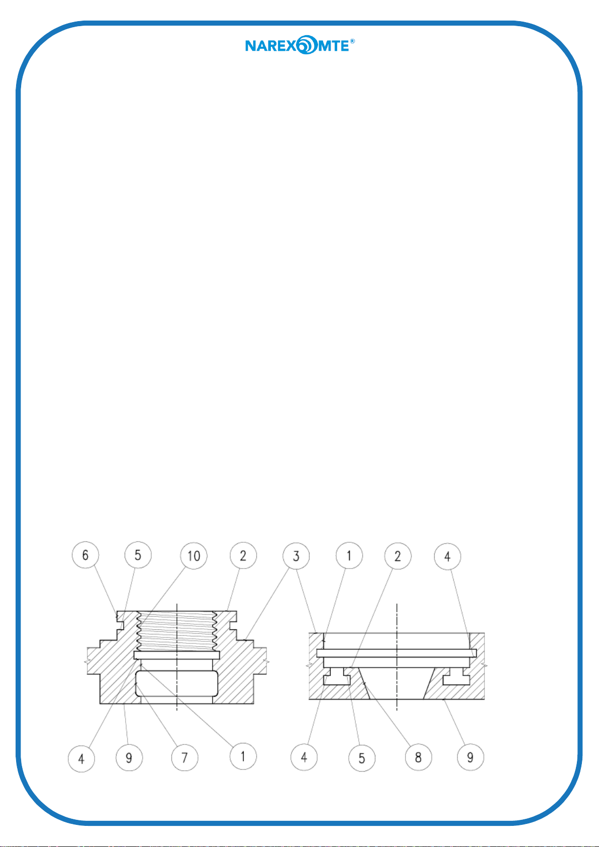
I. Boring and turning of external diameters.
When boring and turning external diameters the operator must avoid touching the breaking ring (1)
which could cause an alteration of the set dimension.
a) To achieve a rapid resetting of the tool slide (5) it is necessary to force an extension socket
spanner into the internal hexagon of the dial for rapid feed motion (12) to a depth of approx.
0,5 in. The tool slide can be now quickly traversed by turning.
One division of the dial for quick traverse of the tool slide stands for the following values:
Vhu 21/8” and 31/8” – feed motion of the tool slide by 0,04in = 0,08in on dia.
Vhu 47/8”and Vhu 6 ¼ ” – feed motion of the tool slide by 0,08in = 0,16 in on dia.
One turn of the screw for rapid feed traverse of the tool slide stands for the following values:
Vhu 21/8” and 31/8” – feed motion of the tool slide by 0,12in = 0,24 in on dia.
Vhu 47/8” and Vhu 6 ¼ ” – feed motion of the tool slide by 0,16in = 0,32in on dia.
After the slide has been reset, the quick traverse screw must be re-locked against turning. Pull
out the socket spanner partly so that a length of only 0,16on will remain on the hole, then turn
the screw in order to set the nearest scale line against the foxed scale mark of the tool slide
(5). Check by turning the spanner to both slides whether the screw is secured against turning.
b) To achieve a fine setting of the tool slide (5) it is necessary to turn the fine setting dial (4) by
means of a socket spanner. The turning of the dial (4) on the direction of the arrow will cause
the tool slide (5) to move also in the direction of the arrow.
One division of the fine setting dial (4) represents a feed motion of the tool slide (5) by
0,00025in = 0,0005in on dia.
When performing precise setting from a larger diameter to a smaller one, reverse the fine
setting dial by more than one half on a turn that would correspond to the dimension, and then
return to the dimension. This will eliminate the effect of tolerances in the transmission
(blacklash).
After the setting has been finished, lock the set dimension by means of the tool slide lock
screw (9). Slight tightening of this screw will help to eliminate the backlash during fine setting.
II. Surfacing on front and rear facings, recessing of external and internal recesses.
a) These operations require a transverse feed of the tool slide (5); the tool slide lock screw must
be loosened (9).
b) The Vhu 2 1/8”, 3 1/8”, 4 7/8” and 6 ¼ ” universal boring heads can be set to automatic
transverse feed of 0,0020, 0,0040, 0,0060 and 0,0080in/rev.
5
 Loading...