

Page 1
ADDENDUM
R
333 Bayview Avenue
Amityville, New York 11701
For Sales and Repairs, (800) 645-9445
For Technical Service, (800) 645-9440
Publicly traded on NASDAQ Symbol: NSSC
ZONE EXPANSION MODULE
GEM-P1664 Control Panel
© NAPCO 2005 WI1418A 5/05
DESCRIPTION
The capacity of the GEM-P1664 control panel may be expanded through the use of a GEM-EZM4/8 Zone Expansion Module. Each
GEM-EZM4/8 module provides up to 16 additional zones, and may be configured in a number of methods: 4 zones, 8 zones, 12 zones
or 16 zones. Using any of these configurations, several GEM-EZM4/8 modules may be combined as necessary to supply the required
number of zones to the GEM-P1664 control panel. Refer to the GEM-P1664 Installation Instructions and GEM-P1664 Programming
Instructions for wiring requirements. Note: Although the GEM-EZM4/8 may also be used with the GEM-P816 and GEM-P1632 control
panels, the features described in this addendum apply only to the GEM-P1664.
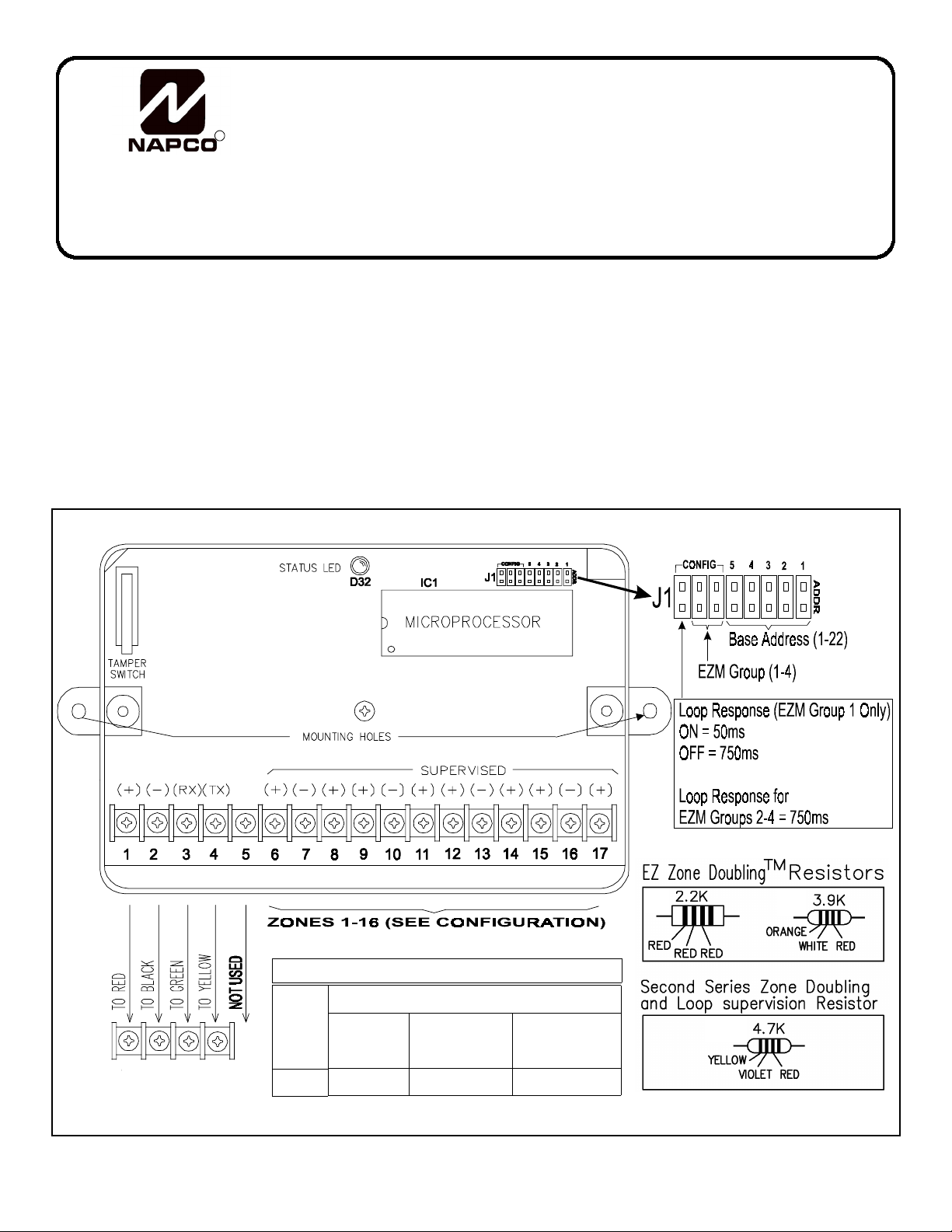
WIRING
Wire the expansion zones to the module and the module to the control panel in accordance with the wiring diagrams shown using
wire no thinner than #22AWG. Install EOL (end-of-line) resistors on all zones even if one or more zones are not used. NOTE: The
addition of Zone Expansion Modules will reduce the amount of current available by 60mA at the control panel's Auxiliary Power Output
terminals.
GEM-EZM4/8 ZONE EXPANSION MODULE
GEM-EZM4/8
for the
9 10 11 12
GEM-P1664
CONTROL PANEL
Current
(
Nominal
Voltage
12VDC
60 mA
SPECIFICATIONS
MAXIMUM LOOP RESISTANCE
Standard Zone
Configuration
)
300 Ohm 100 Ohm 100 Ohm
Primary Zones in
Zone Doubled
Configuration
Secondary Zones in
GEM-EZM4/8 Wiring Diagram
Zone Doubled
Configuration
1
Page 2
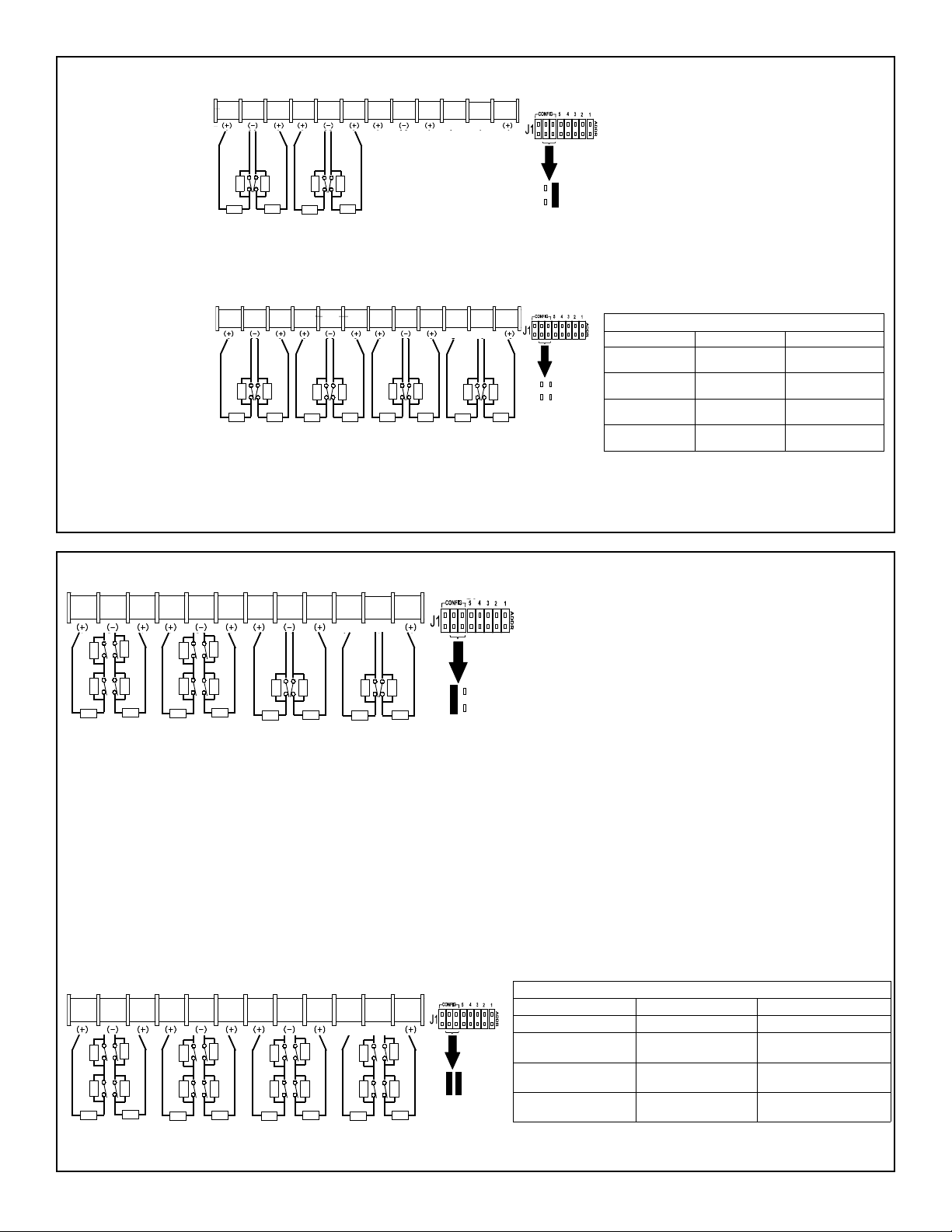
SERIES ZONE AND LOOP SUPERVISION CONFIGURATION (1 EZM-4 ZONES)
g)
Loop supervision with
one contact using a
2.2K across the contact and a 2.2K EOL
resistor, as shown in
the illustration at right:
6 7 8 17 16 15 14 13 12 11 9 10
2.2K
2.2K
2.2K
2.2K
2.2K
2.2K
2.2K
(+) (–)
For "Series Zone and Loop Supervision
Configuration":
1. Do not program NO EOLR (by zone)
2. Program Day Zone on Open (by zone)
2.2K
Configuration = 1 EZM
3. Enable Zone Supervision (global)
SERIES ZONE AND LOOP SUPERVISION CONFIGURATION (2 EZM-8 ZONES)
Loop supervision with
one contact using a
2.2K across the contact and a 2.2K EOL
resistor, as shown in
the illustration at right:
6 7 8 17 16 15 14 13 12 11 9 10
2.2K
2.2K
2.2K
2.2K
2.2K
2.2K
2.2K
(+) (–)
2.2K
2.2K
2.2K
2.2K
2.2K
2.2K
2.2K
2.2K
2.2K
Configuration = 2 EZM
(Default Setting)
"Series Zone and Loop Supervision" Zone Operation
Armed (Set) or 24H Disarmed (unset)
1) Series N/C device
active
2) Parallel N/ O device
active
3) Zone Short Alarm and Day Zone
4) Zone Open Alarm and Day Zone
* Day Zone TBL generates a pulsing keypad sounder,
“DAY ZONE TROUBLE” on LCD and SYS TBL Icon on
when disarmed. A System Trouble E98-00 will remain on
Alarm Zone Fault
N/A N/A
TBL*
TBL*
Day Zone TBL* and Zone
Fault
Day Zone TBL* and Zone
Fault
the system until all day zone troubles have been reset.
SERIES ZONE DOUBLINGTM AND LOOP SUPERVISION (3 EZM-12 ZONES)
6 7 8 17 16 15 14 13 12 11 9 10
(–)
2.2K
Z11
4.7K 2.2K
4.7K 2.2K
2.2K
2.2K
4.7K 2.2K
Z12
2.2K
Z5
Z4
2.2K
Z10
Z3
Z2
4.7K 2.2K
Z9 Z1
2.2K
For "Series Zone Doubling & Loop Supervision" Configuration:
1. Do not program NO EOLR (by zone)
2. Program Day Zone on Open (by zone)
3. Enable Zone Supervision (global)
2.2K
(+)
2.2K
Z7
Z6
2.2K
2.2K
2.2K
2.2K
Z8
Configurat ion = 3 EZM
Each loop has 2 zone resistors (2.2K and 4.7K) for each zone,
and a third 2.2K EOLR provides loop supervision (see diagram).
In loop 1, the 2.2K contact resistor ("Z1") represents the primary
zone and the 4.7K resistor ("Z9") represents the secondary zone.
In the disarmed state, a loop open or shorted (day zone trouble)
will display at the keypad and is reported to the central station (if
selected). The loop supervision function will continue to operate
regardless of the state of the zone contacts on that loop, even if a
loop is bypassed. In the armed state, the loop supervision function will report and display a system trouble notification. When the
door/window contact is actuated by a magnet, the contact is
closed (shorting out the zone resistor). When the contact is open,
the contact places the zone resistor in the circuit. The panel can
detect the following loop conditions, as follows:
A. Loop completely open or shorted: Day Zone Trouble
B. All Contacts closed: Loop Resistance=2.2K (Normal)
C. All Contacts Open: Loop Resistance=9.1K
D. Contact 1 ("Z1") open: Loop Resistance= 4.4K
E. Contact 2 ("Z9") open: Loop Resistance= 6.9K
To activate programming addresses for Zone Doubling and Loop
Supervision, refer to the GEM-P1664 Programming Instructions.
SERIES ZONE DOUBLINGTM AND LOOP SUPERVISION (4 EZM-16 ZONES)
"Series Zone Doubling and Loop Supervision" Zone Operation
6 7 8 17 16 15 14 13 12 11 9 10
2.2K
Z11 Z3
4.7K 2.2K
4.7K 2.2K
Z10
Z2
2.2K
4.7K 2.2K
Z9 Z1
2.2K
2.2K
(–)
(+)
2.2K
Z15
4.7K
2.2K
4.7K 2.2K
4.7K
2.2K
2.2K
Z16
Z8
Configuration = 4 EZM
Z14
Z7
Z6
2.2K
Z13
4.7K 2.2K
4.7K 2.2K
Z12
Z5
Z4
2.2K
1) Series N/C device active Alarm Zone Fault
* Day Zone TBL generates a pulsing keypad sounder, “DAY ZONE TROUBLE” on LCD and SYS TBL Icon on when disarmed. A System Trouble E9800 will remain on the system until all day zone troubles have been reset.
Armed (Set) or 24H Disarmed (unset)
2) Parallel N/O device
active
N/A N/A
3) Zone Short Alarm and Day Zone TBL* Day Zone TBL* and Zone
4) Zone Open Alarm and Day Zone TBL* Day Zone TBL* and Zone
Fault
Fault
2
Page 3

The base address is assigned to the module by proper selection of Address Jumpers (to the right of the LED) in accordance with
the following tables. Also refer to the Zone Wiring Diagram.
GEM-P1664 WITH ZONE DOUBLING
Base Address Jumpers Config.1(EZM)
4 Zone
5 4 3 2 1 Base
Addr
Zone
No.
DISABLED
Config.2 (2EZM)
8 Zone
Base
Addr
Zone
No.
(ZONES 1-8 ON CONTROL PANEL)
Config.3 (3 EZM)
12 Zone
Base
Addr
Zone
No.
Config.4(4 EZM)
16 Zone
Base
Addr
Zone
No.
OFF OFF OFF OFF ON 1 9-12 1,2 9-16 1,2,3 9-20 1,2,3,4 9-24
OFF OFF OFF ON OFF 2 13-16 2,3 13-20 2,3,4 13-24 2,3,4,5 13-28
OFF OFF OFF ON ON 3 17-20 3,4 17-24 3,4,5 17-28 3,4,5,6 17-32
OFF OFF ON OFF OFF 4 21-24 4,5 21-28 4,5,6 21-32 4,5,6,7 21-36
OFF OFF ON OFF ON 5 25-28 5,6 25-32 5,6,7 25-36 5,6,7,8 25-40
OFF OFF ON ON OFF 6 29-32 6,7 29-36 6,7,8 29-40 6,7,8,9 29-44
OFF OFF ON ON ON 7 33-36 7,8 33-40 7,8,9 33-44 7,8,9,10 33-48
OFF ON OFF OFF OFF 8 37-40 8,9 37-44 8,9,10 37-48 8,9,10,11 37-52
OFF ON OFF OFF ON 9 41-44 9,10 41-48 9,10,11 41-52 9,10,11,12 41-56
OFF ON OFF ON OFF 10 45-48 10,11 45-52 10,11,12 45-56 10,11,12,13 45-60
OFF ON OFF ON ON 11 49-52 11,12 49-56 11,12,13 49-60 11,12,13,14 49-64
OFF ON ON OFF OFF 12 53-56 12,13 53-60 12,13,14 53-64
OFF ON ON OFF ON 13 57-60 13,14 57-64
OFF ON ON ON OFF 14 61-64
GEM-P1664 WITH ZONE DOUBLING
Base Address Jumpers Config.1(EZM)
4 Zone
5 4 3 2 1 Base
Addr
ENABLED
Zone
No.
(ZONES 1-16 ON CONTROL PANEL)
Config.2 (2EZM)
8 Zone
Base
Addr
Zone
No.
Config.3 (3 EZM)
Base
Addr
12 Zone
Zone
No.
Config.4(4 EZM)
16 Zone
Base
Addr
Zone
No.
OFF OFF OFF OFF ON 1 17-20 1,2 17-24 1,2,3 17-28 1,2,3,4 17-32
OFF OFF OFF ON OFF 2 21-24 2,3 21-28 2,3,4 21-32 2,3,4,5 21-36
OFF OFF OFF ON ON 3 25-28 3,4 25-32 3,4,5 25-36 3,4,5,6 25-40
OFF OFF ON OFF OFF 4 29-32 4,5 29-36 4,5,6 29-40 4,5,6,7 29-44
OFF OFF ON OFF ON 5 33-36 5,6 33-40 5,6,7 33-44 5,6,7,8 33-48
OFF OFF ON ON OFF 6 37-40 6,7 37-44 6,7,8 37-48 6,7,8,9 37-52
OFF OFF ON ON ON 7 41-44 7,8 41-48 7,8,9 41-52 7,8,9,10 41-56
OFF ON OFF OFF OFF 8 45-48 8,9 45-52 8,9,10 45-56 8,9,10,11 45-60
OFF ON OFF OFF ON 9 49-52 9,10 49-56 9,10,11 49-60 9,10,11,12 49-64
OFF ON OFF ON OFF 10 53-56 10,11 53-60 10,11,12 53-64
OFF ON OFF ON ON 11 57-60 11,12 57-64
OFF ON ON OFF OFF 12 61-64
PROGRAMMING
The control panel must be programmed with regard to the total number of zones required. When keypad programming the
control panel for the first time, the first programming option of the Easy Menu Driven Program Mode will be to enter the total
number of zones in the system, rounded up to the nearest four. You can then support this total by adding the appropriate number
of GEM-EZM4/8 modules which can be configured as 4, 8, 12 or 16 zone modules. The number of modules required is a function
of the number of zones required as well as the configuration of the EZM's. If 24 additional zones are required and Config 2 (8
zones) is chosen, the number of EZM's required will be 24/8 = 3 EZM's.
When downloading a control panel, the total number of zones is determined on the Zone Features screen by activating the
required number of EZM modules in the System Configuration screen.
For Fire Zones, if an EZM module is selected as Config 3 or Config 4, which are both zone doubled configurations, and one of
these doubled zones is programmed as a fire zone, the complimentary zone is lost. For example, if an EZM is configured as a 16
zone module (Config 4), and zone 1 of the module is programmed as a Fire Zone, zone 9 of the module will lose the zone doubling
profile and cannot be used. It must be strapped out with a Z resistor (3.9K) across the zone. Zone 9 must be skipped in your
control panel programming, and the next available zone will be Zone 10.
TAMPER
If the cover is removed, the keypad sounder will pulse, and the display will indicate a zone-module tamper condition along with
the module number. Press
to silence the sounder.
C
3
Page 4

LOOP RESPONSE
Loop response times for Zones 1 through 8 are programmed in the control panel. Normal loop response for all expansion
zones is 750mS. The module already comes without the jumper installed (defaulted to 750ms). To reduce the response time of
zones 1 through 4 of the EZM Module to 50mS, add the Loop Response Jumper. To enable normal loop response (750 ms),
remove the jumper. Refer to the Wiring Diagram.
STATUS LED
The Status LED displays the condition of the zone module. The following is a list of conditions for the LED:
1. OFF = Control Panel has no power applied.
2. ON Steady = Control Panel has power applied but the panel is not polling because:
a. the panel is in "CONFIG",
b. the panel is not programmed correctly to poll the address of the EZM,
c. the GRN wire is not connected correctly.
3. PULSES off the EZM groups that are being polled.
a. If the first EZM group (the base number) is polled the LED is normally on and pulses off once slowly.
b. If the first and second EZM group are polled then the LED is normally on and pulses off once then twice sequentially.
c. If the first, second, third and fourth groups are polled the LED is normally off and will pulse 1, 2, 3, 4 sequentially.
4. Rapid Flashing.
a. GEM-EZM4/8 is connected to wrong panel type.
Only GEM-P1664 may be connected.
NOTE:
NAPCO LIMITED WARRANTY
NAPCO SECURITY SYSTEMS, INC. (NAPCO) warrants its
products to be free from manufacturing defects in materials and
workmanship for thirty-six months following the date of manufacture.
NAPCO will, within said period, at its option, repair or replace any
product failing to operate correctly without charge to the original
purchaser or user.
This warranty shall not apply to any equipment, or any part
thereof, which has been repaired by others, improperly installed,
improperly used, abused, altered, damaged, subjected to acts of God,
or on which any serial numbers have been altered, defaced or
removed. Seller will not be responsible for any dismantling or
reinstallation charges.
THERE ARE NO WARRANTIES, EXPRESS OR IMPLIED,
WHICH EXTEND BEYOND THE DESCRIPTION ON THE FACE
HEREOF. THERE IS NO EXPRESS OR IMPLIED WARRANTY OF
MERCHANTABILITY OR A WARRANTY OF FITNESS FOR A
PARTICULAR PURPOSE. ADDITIONALLY, THIS WARRANTY IS IN
LIEU OF ALL OTHER OBLIGATIONS OR LIABILITIES ON THE
PART OF NAPCO.
Any action for breach of warranty, including but not limited to any
implied warranty of merchantability, must be brought within the six
months following the end of the warranty period. IN NO CASE SHALL
NAPCO BE LIABLE TO ANYONE FOR ANY CONSEQUENTIAL OR
INCIDENTAL DAMAGES FOR BREACH OF THIS OR ANY OTHER
WARRANTY, EXPRESS OR IMPLIED, EVEN IF THE LOSS OR
DAMAGE IS CAUSED BY THE SELLER'S OWN NEGLIGENCE OR
FAULT.
In case of defect, contact the security professional who installed
and maintains your security system. In order to exercise the warranty,
the product must be returned by the security professional, shipping
costs prepaid and insured to NAPCO. After repair or replacement,
NAPCO assumes the cost of returning products under warranty.
NAPCO shall have no obligation under this warranty, or otherwise, if
the product has been repaired by others, improperly installed,
improperly used, abused, altered, damaged, subjected to accident,
nuisance, flood, fire or acts of God, or on which any serial numbers
have been altered, defaced or removed. NAPCO will not be
responsible for any dismantling, reassembly or reinstallation charges.
This warranty contains the entire warranty. It is the sole warranty
and any prior agreements or representations, whether oral or written,
are either merged herein or are expressly cancelled. NAPCO neither
assumes, nor authorizes any other person purporting to act on its
behalf to modify, to change, or to assume for it, any other warranty or
liability concerning its products.
In no event shall NAPCO be liable for an amount in excess of
NAPCO's original selling price of the product, for any loss or damage,
whether direct, indirect, incidental, consequential, or otherwise arising
out of any failure of the product. Seller's warranty, as hereinabove set
forth, shall not be enlarged, diminished or affected by and no
obligation or liability shall arise or grow out of Seller's rendering of
technical advice or service in connection with Buyer's order of the
goods furnished hereunder.
NAPCO RECOMMENDS THAT THE ENTIRE SYSTEM BE
COMPLETELY TESTED WEEKLY.
Warning: Despite frequent testing, and due to, but not limited to,
any or all of the following; criminal tampering, electrical or
communications disruption, it is possible for the system to fail to
perform as expected. NAPCO does not represent that the product/
system may not be compromised or circumvented; or that the product
or system will prevent any personal injury or property loss by burglary,
robbery, fire or otherwise; nor that the product or system will in all
cases provide adequate warning or protection. A properly installed
and maintained alarm may only reduce risk of burglary, robbery, fire
or otherwise but it is not insurance or a guarantee that these events
will not occur. CONSEQUENTLY, SELLER SHALL HAVE NO
LIABILITY FOR ANY PERSONAL INJURY, PROPERTY DAMAGE,
OR OTHER LOSS BASED ON A CLAIM THE PRODUCT FAILED TO
GIVE WARNING. Therefore, the installer should in turn advise the
consumer to take any and all precautions for his or her safety
including, but not limited to, fleeing the premises and calling police or
fire department, in order to mitigate the possibilities of harm and/or
damage.
NAPCO is not an insurer of either the property or safety of the
user's family or employees, and limits its liability for any loss or
damage including incidental or consequential damages to NAPCO's
original selling price of the product regardless of the cause of such
loss or damage.
Some states do not allow limitations on how long an implied
warranty lasts or do not allow the exclusion or limitation of incidental
or consequential damages, or differentiate in their treatment of
limitations of liability for ordinary or gross negligence, so the above
limitations or exclusions may not apply to you. This Warranty gives
you specific legal rights and you may also have other rights which
vary from state to state.
4
 Loading...