

Page 1
FW-RA-LED
Remote Multiplex Annunciator Panels
WIRING and INSTALLATION INSTRUCTION
LNOTICE
All information, documentation, and specifications contained in this manual are subject to change without prior
notice by the manufacturer.
©1999 by NAPCO Security Systems, Inc.
Printed July 22, 1999
LT-648NAP
Page 2
INTRODUCTION:
NAPCO’s FW-RA-LED Annunciator is an 8 Circuit Annunciator for use with NAPCO’s FW-C2Z, FW-C4Z, FW-C4EZ Fire Alarm
Control Panels, that mounts into a standard 4-gang electrical boxes, which may not be expanded. Control access is by a
keyswitch. Each Circuit Indicator is a bi-colour LED that is automatically configured to match the Fire Alarm Control Panel
configuration.
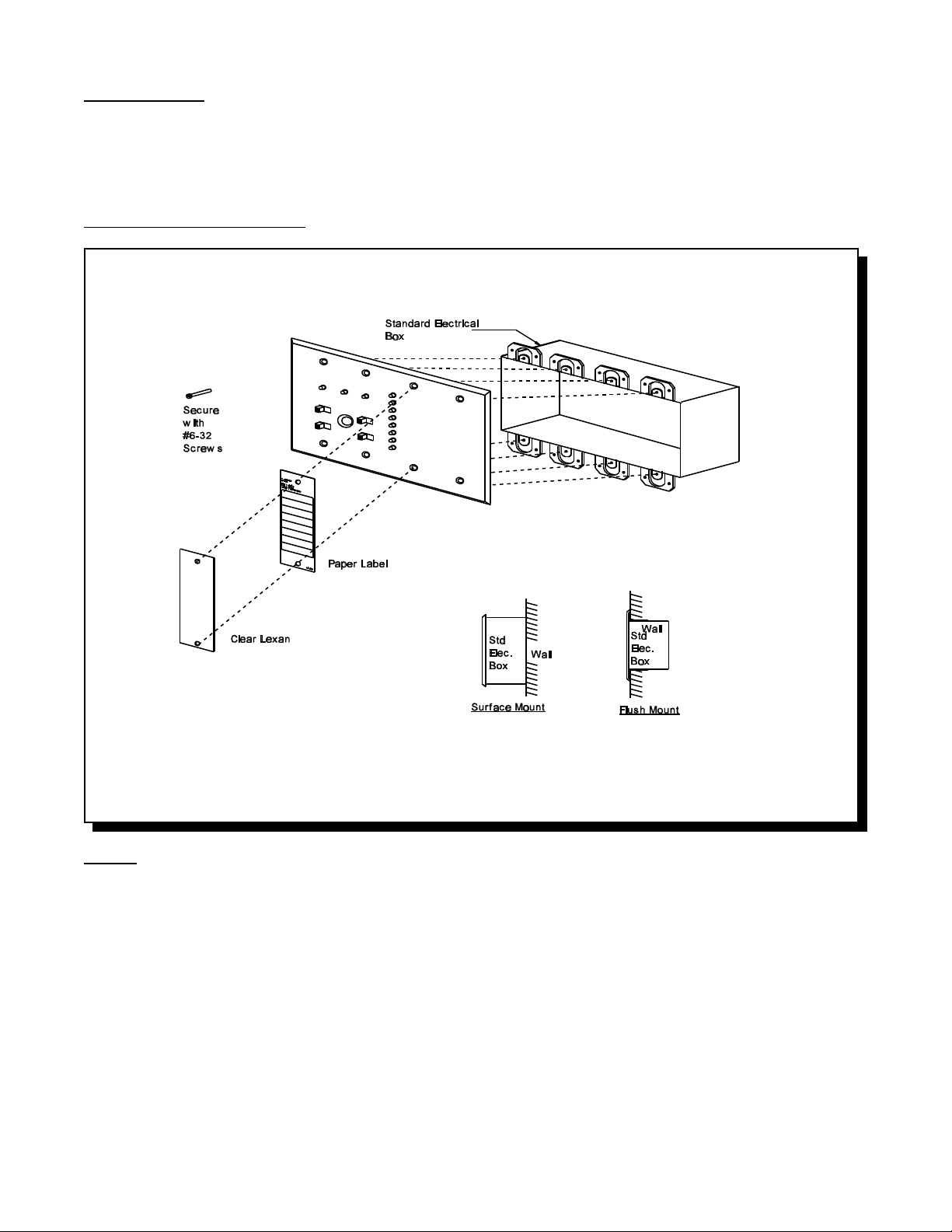
INSTALLATION INSTRUCTION:
NOTES: Note that the FW-RA-LED is supplied with NP-386NAP Labels.
This Annunciator displays Initiating Circuit Status only (no individual Circuit Troubles). Indicating and Relay
Circuits are not remotely displayed. See the Fire Alarm Control Panel Manual for more details.
The FW-RA-LED has a keyswitch to enable the four slide-switch controls. The key should be appropriately
secured.
2
Page 3

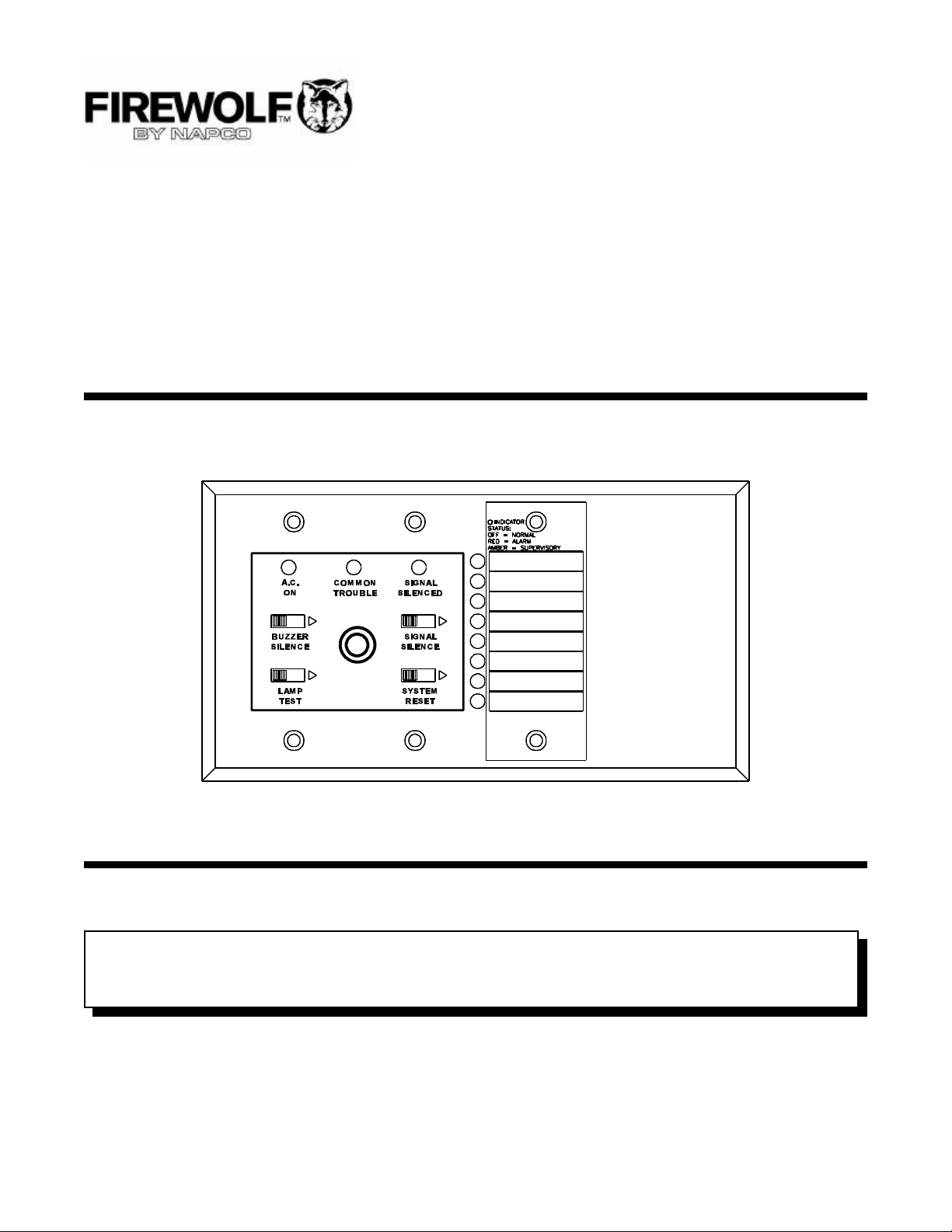
CONTROLS & DISPLAYS:
For precise definitions of Control & Display operation, refer to the manual for the Fire Alarm Control Panel that the Annunciator
is being connected to.
Controls Displays
System Reset, Signal Silence, AC On, Common Trouble, Signal Silence,
Buzzer Silence, Lamp Test. 8 Circuit Status LED’s.
WIRING INSTRUCTION:
The RS-485 Wiring to the FW-RA-LED Module is
recommended to be Twisted Shielded Pair as
shown in the diagram. The wire gauge may be;
22 AWG up to 2000 ft.
20 AWG up to 4000 ft.
18 AWG up to 8000 ft.
The RS-485 wiring from the Fire Alarm Control
Panel to the Annunciator(s) must be point-to-point
from the FA Panel to the first Annunciator, then the
next Annunciator, and so on. No star-wiring or T-
tapping is allowed. Each RAM-208 Annunciator
Module has a 120 ohm End-of-Line Resistor on
its RS-485 Output terminals. This is removed on
all except the last wired Module.
The 24 VDC field wiring needs to be of an
appropriate gauge for the number of annunciators
and the total wiring run length. See the
Specifications section “Current Drain for Battery
Calculations”, and calculate the Maximum current
for all Annunciators summed together ...
NOTE: Accidentally connecting any of the 24
VDC wires to the RS-485 wiring could
result in damage to the Annunciator
and/or to the Fire Alarm Control Panel that it is connected to !!!
Maximum for MAXIMUM WIRING RUN TO LAST ANNUNCIATOR MAX. LOOP
all Annunciators RESISTANCE
18AWG 16AWG 14AWG 12AWG
Amperes ft m ft m ft m ft m Ohms
0.30 470 143 750 229 1200 366 1900 579 6
0.60 235 71 375 114 600 183 850 259 3
0.90 156 47 250 76 400 122 570 174 2
1.20 118 36 185 56 300 91 425 129 1.5
1.50 94 29 150 46 240 73 343 105 1.2
1.70 78 24 125 38 200 61 285 87 1.0
3
Page 4

DIP SWITCH SETTINGS:
Each Annunciator needs to be assigned a unique, sequential “Address”. This is done with DIP Switches, which also
allow disabling of some buttons.
SW1-1 = Address A0 \
SW1-2 = Address A1 > Address “A3” is always “off”.
SW1-3 = Address A2 /
SW1-4 = When “off”, the System Reset and Signal Silence slide-switches are always disabled, regardless of the
operation of the keyswitch.
The Annunciator “Address” (see the Manual for the Fire Alarm Control Panel being used), is set as ...
Annunciator “Address”
DIP Switch Positions
SW1-1 (A0) on off on off on off on
SW1-2 (A1) off on on off off on on
SW1-3 (A2) off off off on on on on
SW1-4 (A3) off off off off off off off
1 2 3 4 5 6 7
Annunciators on a common RS-485 connection must be numbered sequentially; i.e.: 1,2,3,4, and not randomly
such as 5,3,7 !! Note that not all Annunciator “Addresses” are valid for all Fire Alarm Control Panels. Refer
to the Fire Alarm Control Panel Manual for further information.
SPECIFICATIONS & FEATURES
Enclosure:
A standard 4-gang Electrical Box is used.
Electrical Specs.:
Ž 19 to 31 VDC (filtered or full-wave-rectified)
Ž Slide-Switch Controls, LED indicators, and Keyswitch to enable Controls.
Ž Local Buzzer, Indicators (AC-On, Common Trouble, Signal Silence), and Controls (System Reset, Lamp Test, Buzzer
Silence, Signal Silence).
Ž Annunciation of up to 8 Points.
Ž Not Expandable.
Ž Standby: 35 mA Max., All LED’s “On”: 90 mA Max.
Current Drain for Battery Calculations:
The maximum normal current drain will be during Lamp Test when all lamps are illuminated on one chassis at a time. Thus
the currents are ...
Normal Standby = 35 mA Maximum = 90 mA
The Normal Standby Current is used for Battery Size Calculations (see the Fire Alarm Control Panel manual) and includes
the current drain for the Trouble Buzzer, Trouble LED, and one Alarm LED. The Maximum Current is used to calculate the wire
size (see the Wiring Instruction).
4
Page 5

WARRANTY
NAPCO SECURITY SYSTEMS, INC. (NAPCO) by the security professional, shipping costs prepaid and
warrants its products to be free from manufacturing insured to NAPCO. After repair or replacement,
defects in materials and workmanship for 12 months NAPCO assumes the cost of returning products under
following the date of manufacture. NAPCO will, within warranty. NAPCO shall have no obligation under this
said period, at its option, repair or replace any product warranty, or otherwise, if the product has been repaired
failing to operate correctly without charge to the original by others, improperly used, abused, altered, damaged,
purchaser or user. subjected to accident, nuisance, flood, fire or acts of
God, or on which any serial numbers have been altered,
This warranty shall not apply to any equipment, or any defaced or removed. NAPCO will not be responsible for
part thereof, which has been repaired by others, any dismantling, reassembly or reinstallation charges.
improperly installed, improperly used, abused, altered,
damaged, subjected to acts of God, or on which any This warranty contains the entire warranty. It is the
serial numbers have been altered, defaced or removed. sole warranty and any prior agreements or
Seller will not be responsible for any dismantling or representations, whether oral or written, are either
reinstallation charges. merged herein or are expressly cancelled. NAPCO
neither assumes, nor authorizes any other person
THERE ARE NO WARRANTIES, EXPRESS OR purporting to act on its behalf to modify, to change, or
IMPLIED, WHICH EXTEND BEYOND THE to assume for it, any other warranty or liability
DESCRIPTION ON THE FACE HEREOF. THERE IS concerning its products.
NO EXPRESS OR IMPLIED WARRANTY OF
MERCHANTABILITY OR A WARRANTY OF FITNESS In no event shall NAPCO be liable for an amount in
FOR A PARTICULAR PURPOSE. ADDITIONALLY, excess of NAPCO’s original selling price of the product,
THIS WARRANTY IS IN LIEU OF ALL OTHER for any loss or damage, whether direct, indirect,
OBLIGATIONS OR LIABILITIES ON THE PART OF incidental, consequential, or otherwise arising out of
NAPCO. any failure of the product. Seller’s warranty, was herein
above set forth, shall not be enlarged, diminished or
Any action for breach of warranty, including but not affected by and no obligation or liability shall arise or
limited to any implied warranty of merchantability, must grow out of Seller’s rendering of technical advice or
be brought within the six months following the end of service in connection with Buyer’s order of the goods
the warranty period. furnished hereunder.
IN NO CASE SHALL NAPCO BE LIABLE TO ANYONE NAPCO RECOMMENDS THAT THE ENTIRE SYSTEM
FOR ANY CONSEQUENTIAL OR INCIDENTAL BE COMPLETELY TESTED WEEKLY.
DAMAGES FOR BREACH OF THIS OR ANY OTHER
WARRANTY, EXPRESS OR IMPLIED, EVEN IF THE Warning: Despite frequent testing, and due to, but not
LOSS OR DAMAGE IS CAUSED BY THE SELLER’S limited to, any or all of the following; criminal tampering,
OWN NEGLIGENCE OR FAULT. electrical or communications disruption, it is possible
for the system to fail to perform as expected. NAPCO
In case of defect, contact the security professional who does not represent that the product/system may not be
installed and maintains your security system. In order compromised or circumvented; or that the product or
to exercise the warranty, the product must be returned system will prevent any personal injury or property loss
5
Page 6

by burglary, robbery, fire or otherwise; nor that the NAPCO is not an insurer of either the property or safety
product or system will in all cases provide adequate of the user’s family of employees, and limits its liability
warning or protection. A properly installed and for any loss or damage including incidental or
maintained alarm may only reduce risk of burglary, consequential damages to NAPCO’s original selling
robbery, fire or otherwise but it is not insurance or a price of the product regardless of the cause of such
guarantee that these events will not occur. loss or damage.
CONSEQUENTLY, SELLER SHALL HAVE NO
LIABILITY FOR ANY PERSONAL INJURY, PROPERTY Some states do not allow limitations on how long an
DAMAGE, OR OTHER LOSS BASED ON A CLAIM implied warranty lasts or do not allow the exclusions or
THE PRODUCT FAILED TO GIVE WARNING. limitation of incidental or consequential damages, or
Therefore, the installer should in turn advise the differentiate in their treatment of limitations of liability for
consumer to take any and all precautions for his or her ordinary or gross negligence, so the above limitations
safety including, but not limited to, fleeing the premises or exclusions may not apply to you. This warranty
and calling police or fire department, in order to mitigate gives you specific legal rights and you may also hav e
the other rights which vary from state to state.
possibilities of harm and/or damage.
Head Office:
FIREWOLF Advanced Fire Products
NAPCO Security Systems, Inc.
333 Bayview Avenue
AMITYVILLE, N.Y.
U.S.A. 11701
Phone: (516) 842-9400
IN NORTH AMERICA Phone: 1-800-645-9445
FAX Toll Free: (516) 789-9292
Web Page: http://www.napcosecurity.com
e-mail: techinfo@napcosecurity.com
6
 Loading...