

Page 1
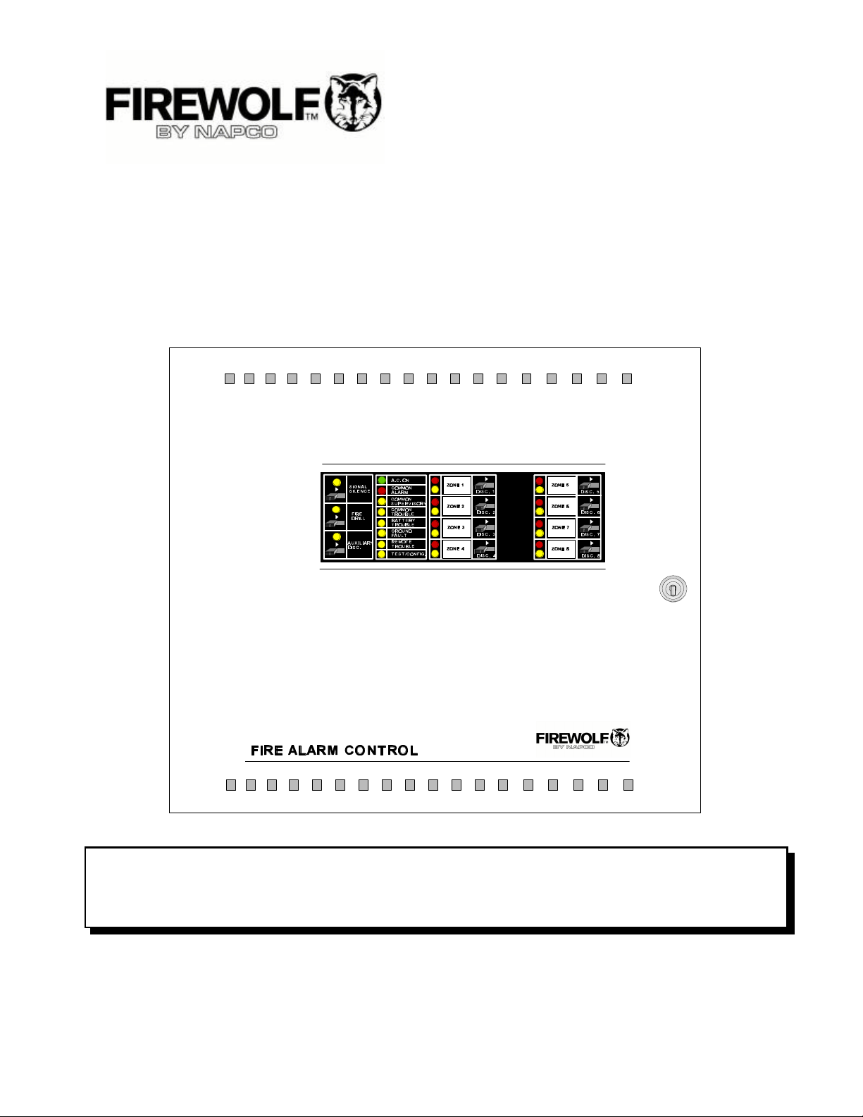
FW-C2Z, FW-C4Z and FW-C4EZ
Microprocessor Based - Fire Alarm Control Panels
INSTALLATION and OPERATION MANUAL
LNOTICE
All information, documentation, and specifications contained in this manual are subject to change
without prior notice by the manufacturer.
©1999 by NAPCO Security Systems, Inc.
Printed in CANADA, September 23, 1999
LT-636NAP Rev.1 (Operating Instruction is NP-779NAP Rev.1)
Page 1 of 36
Page 2

TABLE of CONTENTS
1.0 INTRODUCTION ...................................................................................... Page 4 of 36
1.1 OVERALL FEATURES: ............................................................................. Page 4 of 36
2.0 GENERAL NOTES .................................................................................... Page 5 of 36
3.0 SYSTEM COMPONENTS .............................................................................. Page 6 of 36
3.1 MODELS ........................................................................................ Page 7 of 36
3.2 ACCESSORIES .................................................................................. Page 7 of 36
4.0 MECHANICAL INSTALLATION and DIMENSIONS .......................................................... Page 8 of 36
5.0 MODULE MOUNTING LOCATIONS ...................................................................... Page 10 of 36
6.0 MODULE SETTINGS .................................................................................. Page 12 of 36
6.1 MAIN FIRE ALARM MODULE ........................................................................ Page 12 of 36
6.2 ZONE EXPANSION MODULE (Model FW-EZM4) ........................................................ Page 13 of 36
6.3 RELAY MODULES (Models FW-RB4 or FW-RB8) ....................................................... Page 13 of 36
6.4 DACT / DIALER MODULE (Model FW-DACT) ........................................................... Page 14 of 36
6.5 POLARITY REVERSAL and CITY TIE MODULE (MODEL: FW-RPM) ........................................ Page 14 of 36
7.0 FIELD WIRING ....................................................................................... Page 15 of 36
7.1 GENERAL FIELD WIRING CONSIDERATIONS .......................................................... Page 15 of 36
7.2 MAIN FIRE ALARM MODULE TERMINAL CONNECTIONS ................................................ Page 16 of 36
7.3 ZONE EXPANSION MODULE (FW-EZM4) TERMINAL CONNECTIONS ...................................... Page 18 of 36
7.4 RELAY MODULE ( FW-RB4 or FW-RB8) TERMINAL CONNECTIONS ....................................... Page 19 of 36
7.5 DACT / DIALER MODULE (FW-DACT) TERMINAL CONNECTIONS ......................................... Page 20 of 36
7.6 POLARITY REVERSAL and CITY TIE MODULE (MODEL: FW-RPM) TERMINAL CONNECTIONS ................ Page 20 of 36
7.7 POWER SUPPLY CONNECTIONS ................................................................... Page 21 of 36
7.8 WIRING TABLES ................................................................................. Page 22 of 36
WIRING TABLE FOR INITIATING CIRCUITS ........................................................... Page 22 of 36
WIRING TABLE FOR NOTIFICATION CIRCUITS ........................................................ Page 22 of 36
8.0 SYSTEM CHECKOUT ................................................................................. Page 23 of 36
8.1 BEFORE TURNING THE POWER "ON" ............................................................... Page 23 of 36
8.2 POWER-UP PROCEDURE ......................................................................... Page 23 of 36
8.3 TROUBLESHOOTING ............................................................................. Page 23 of 36
9.0 INDICATORS, CONTROLS, & OPERATION ................................................................ Page 24 of 36
9.1 INDICATORS .................................................................................... Page 25 of 36
9.2 CONTROLS ..................................................................................... Page 26 of 36
9.3 OPERATION ..................................................................................... Page 26 of 36
9.4 CIRCUIT TYPES .................................................................................. Page 27 of 36
10.0 SYSTEM CONFIGURATION ............................................................................ Page 28 of 36
11.0 WALK TEST OPERATION .............................................................................. Page 30 of 36
APPENDIX "A" - COMPATIBLE DEVICES .................................................................... Page 31 of 36
APPENDIX "B" - FW-RB8 REMOTE ANNUNCIATOR ........................................................... Page 33 of 36
APPENDIX "C" - MODULE SPECIFICATIONS and FEATURES ................................................... Page 34 of 36
APPENDIX "D" - POWER SUPPLY & BATTERY CALCULATIONS (SELECTION GUIDE) .............................. Page 35 of 36
WARRANTY ............................................................................................. Page 36 of 36
Page 2 of 36
Page 3

TABLE of FIGURES
Fig.1: FW-C2Z, FW-C4Z Enclosure Installation and Dimensions .................... Page 8 of 36
Fig.2: FW-C4EZ Enclosure Installation and Dimensions .......................... Page 9 of 36
Fig.3: FW-C2Z, FW-C4Z Module Mounting Locations ............................. Page 10 of 36
Fig.4: FW-C4EZ Module Mounting Locations ................................... Page 11 of 36
Fig.5: Main Fire Alarm Module ............................................... Page 12 of 36
Fig.6: FW-EZM4 Zone Expansion Module ...................................... Page 13 of 36
Fig.7: FW-RB4 or FW-RB8 Relay Module ....................................... Page 13 of 36
Fig.8: FW-DACT Dialer Module ............................................... Page 14 of 36
Fig.9: FW-RPM City Tie Module .............................................. Page 14 of 36
Fig.10: General Field Wiring Considerations ..................................... Page 15 of 36
Fig.11: Main Fire Alarm Module Terminal Connections ............................ Page 16 of 36
Fig.11a: Main Fire Alarm Module Terminal Connections (continued) .................. Page 17 of 36
Fig.12: FW-EZM4 Zone Expansion Module Terminal Connections ................... Page 18 of 36
Fig.13: FW-RB4 / FW-RB8 Relay Terminal Connections ............................ Page 19 of 36
Fig.14: FW-RPM Polarity Reversal and City Tie Module Terminal Connections ......... Page 20 of 36
Fig.15: Power Supply Connections ............................................ Page 21 of 36
Fig.16: WIRING TABLE FOR INITIATING CIRCUITS ............................... Page 22 of 36
Fig.17: WIRING TABLE FOR NOTIFICATION CIRCUITS ............................ Page 22 of 36
Fig.18: Indicators and Control Location ........................................ Page 24 of 36
Page 3 of 36
Page 4

1.0 INTRODUCTION
Introduction :
NAPCO's FW-C2Z, FW-C4Z and FW-C4EZ 24 Volt Fire Alarm Control Panels provide 1,2, 4, or 8 supervised Class
B (UL Style B) Initiating Circuits, or 1,2, 4 supervised Class A (UL Style D) Initiating Circuits, and 2 or 4 supervised
Class A or B (UL Style Z or Y) Notification Circuits. All Circuits are supervised for opens and ground faults, and
Notification Circuits for shorts. Optional Modules include a FW-EZM4 Zone Expansion (required for full capacity in the
FW-C4EZ only), a FW-DACT Dialer or a FW-RPM Polarity Reversal & City Tie Module, and FW-RB4 or FW-RB8
Relay Modules. The two enclosures are flush or surface mountable, and can be used for retrofits and on new
installations.
1.1 Overall Features:
T The small enclosure versions, FW-C2Z, & FW-C4Z have 1, 2, 4 Class B (Style B) Initiating Circuits
respectively. The FW-C2Z & FW-C4Z may be configured as 1 or 2 Class A (Style D) Circuits respectively.
These also have 2 Power Limited Class A/B (Style Z/Y) Notification Circuits with individual trouble indicators.
T The large enclosure version, FW-C4EZ, has 4 Class B (Style B) Initiating Circuits which may be configured
as 2 Class A (Style D) Circuits respectively. It also has 2 Power Limited Class A/B (Style Z/Y) Notification
Circuits with individual trouble indicators. With a FW-EZM4 Zone Expansion, an extra 4 Class B (2 Class A)
Initiating Circuits, and 2 Class A/B Notification Circuits are added.
T Each Initiating Circuit is configurable as a Normal or Verified Alarm. In addition, on a Class B FW-C4Z or FW-
C4EZ, Initiating Circuit 3 may be a Waterflow Zone (as may Initiating Circuit 7 if a FW-EZM4 is installed), and
Initiating Circuit 4 may be a Latched or Non-Latched Supervisory Zone (as may Initiating Circuit 8 if a FWEZM4 is installed). On a Class A FW-C4EZ with a FW-EZM4, Initiating Circuit 3 may be a Waterflow Zone, and
Initiating Circuit 4 may be a Latched or Non-Latched Supervisory Zone.
T Notification Circuits can be configured as Audible or Visual and as silenceable or non-silenceable. Audibles
may be Steady, Temporal Code, California Code, or March Time.
T Initiating Circuits may be individually Disconnected by a Slide-Switch.
T Configurable Signal Silence Inhibit (disabled or 1 minute), Auto Signal Silence (disabled or 5, 10, 20 minutes) ,
and One-Man Walk Test.
T Subsequent Alarm, Supervisory, and Trouble operation
T 4 wire resettable Smoke Power Supply (100 mA Max.).
T Auxiliary relay contacts for Common Alarm and Common Supervisory (disconnectable), and a Common
Trouble relay.
T Interface for an RTI Remote Trouble Indicator.
T RS-485 Interface for 1 to 3 of FW-RB8 Remote Multiplex Annunciators on FW-C4Z & FW-C4EZ.
T The FW-C2Z and FW-C4Z may use one of optional FW-DACT (Dialer), FW-RPM (City Tie), FW-RB4 or FW-
RB8 Relay Modules.
T The FW-C4EZ may use one of optional FW-DACT (Dialer), FW-RPM (City Tie), and also one of FW-RB4 or
FW-RB8 Relay Modules.
T Slide Switch Controls and LED Common Indicators.
T Easy Configuration via DIP Switches.
T Extensive transient protection
Page 4 of 36
Page 5

2.0 GENERAL NOTES
Circuits and Zones:
“Circuits” refers to an actual electrical interface, Initiating (Detection), Indicating (Signal), or Relay.
“Zone” is a logical concept for a Fire Alarm Protected Area, and will consist of at least one Circuit.
Often the terms Zone and Circuit are used interchangeably, but in this Manual the term Circuit is used.
Wiring Styles:
Initiating Circuits are configured by default as Class B (Style B). They may be globally (all or none) configured as
Class A (Style D) as described in the Configuration Section. This operation uses odd and even pairs of two-wire Class
B (Style B) circuits to make one four-wire Class A (Style D) circuit, thus cutting in half the number of available Initiating
Circuits.
Notification Circuits may be individually wired as Class A (Style Z) or Class B (Style Y) without affecting the number
of circuits available (see Module wiring instructions).
Note: All Class B (Style B) initiating circuits are 2 wire smoke detector compatible. These circuits are current limited
to 100 mA max. Refer to table on page 32 for a list of compatible smoke detectors.
Page 5 of 36
Page 6
3.0 SYSTEM COMPONENTS
Model: FW-C2Z,C4Z Fire Alarm Control Panel Model: FW-RPM City Tie Module
FW-C4Z
ZONE 1
ZONE 2
ZONE 3
FIRE ALARM CONTROL PANEL
Model: FW-C4EZ Fire Alarm Control Panel
ZONE 4
Model: FW-DACT Dialer Module
ZONE 1
ZONE 5
ZONE 2
ZONE 6
ZONE 3
ZONE 7
ZONE 4
ZONE 8
FIRE ALARM CONTROL
Model: FW-EZM4 Zone Expansion Module
Model: FW-RB4 & FW-RB8 4 & 8 Relay Module
Page 6 of 36
Page 7

3.1 MODELS
Model: FW-C2Z Small enclosure Fire Alarm Control Panel with two Class B (Style B) or one Class A (Style D) Initiating Circuits,
and 2 Power Limited Class A/B (Style Z/Y) Notification Circuits (1.70 amperes each, 2.4 amperes total) with
individual trouble indicators. Common Alarm & Trouble Relays. Interface for Remote Trouble Indicator.
Resettable Four Wire Smoke Detector Power Supply. May have one of FW-DACT, FW-RPM, FW-RB4, or
FW-RB8 installed. Can be used with 4 amp-hour or 6.5 amp-hour batteries (2 required).
Model: FW-C4Z Small enclosure Fire Alarm Control Panel with four Class B (Style B) or two Class A (Style D) Initiating
Circuits, and 2 Power Limited Class A/B (Style Z/Y) Notification Circuits (1.70 amperes each, 2.4 amperes
total) with individual trouble indicators. Common Alarm & Trouble Relays. Interface for Remote Trouble
Indicator and/or 1 to 3 of FW-RB8 Remote Multiplex Annunciators. Resettable Four Wire Smoke Detector
Power Supply. May have one of FW-DACT, FW-RPM, FW-RB4, or FW-RB8 installed. Can be used with 4
amp-hour or 6.5 amp-hour batteries (2 required).
Model: FW-C4EZ Large enclosure Fire Alarm Control Panel with four Class B (Style B) or two Class A (Style D) Initiating
Circuits, and 2 Power Limited Class A/B (Style Z/Y) Notification Circuits (1.70 amperes each, 5 amperes total)
with individual trouble indicators. Common Alarm & Trouble Relays. Interface for Remote Trouble Indicator
and/or 1 to 3 of FW-RB8 Remote Multiplex Annunciators. Resettable Four Wire Smoke Detector Power
Supply. May have one of FW-DACT or FW-RPM, and one FW-EZM4 installed. May also have one of FW-RB4
or FW-RB8 installed. Can be used with 4 amp-hour, 6.5 amp-hour, or 10 amp-hour batteries (2 required).
Model: FW-EZM4 Zone Expansion Module for the FW-C4EZ. Brings the total capacity to eight Class B (Style B) or four Class
A (Style D) Initiating Circuits, and 4 Power Limited Class A/B (Style Z/Y) Notification Circuits (up to 1.7
amperes each, 5 amperes total).
Model: FW-RB8 Relay Module for the FW-C4Z or FW-C4EZ. Adds eight configurable Form-C Relays rated 1A, 28 VDC.
Model: FW-RB4 Relay Module for the FW-C4Z or FW-C4EZ. Adds four configurable Form-C Relays rated 1A, 28 VDC.
Model: FW-DACT Digital Communicator / Dialer Module.
Model: FW-RPM City Tie / Reverse Polarity Module.
Model: CH-429 Accessory Mounting Plate for the FW-C2Z, or FW-C4Z if one of FW-RB4, FW-RB8, FW-RPM, or FW-DACT
Modules are to be used.
3.2 ACCESSORIES
Model: FW-RA-LED 8 Zone Remote Annunciator (ULC and UL Approved)
Model: FW-RTI Remote Trouble Indicator (ULC and UL Approved)
Page 7 of 36
Page 8
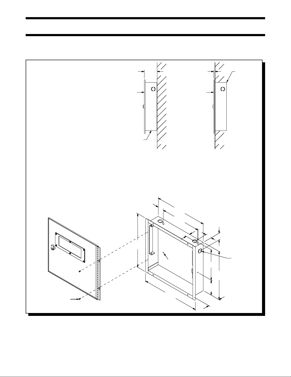
4.0 MECHANICAL INSTALLATION and DIMENSIONS
Install the enclosure as shown below for the FW-C2Z or FW-C4Z ...
Fig.1: FW-C2Z or FW-C4Z Enclosure Installation and Dimensions
MATERIAL: 18GA (0.048") THICK
COLD ROLLED STEEL
FINISH: PAINTED
DOOR
DOOR
BACKBOX
3
"
-
3
8
WALL
SURFACE
(SIDE VIEW)
5
"
-
1
8
DOOR
BACKBOX
3
"
-
13
4
1
"
-
10
2
5
"
-
16
WALL
FLUSH
(SIDE VIEW)
BACKBOX
#6 x 5/16" SCREW
1
"
-
14
8
Page 8 of 36
15
32
5
"
-
1
"
7
"
-
DIA.
HOLE
1
"
-
8
1
3
3
"
-
8
1
4
7
1
"&"
-
-
1
8
8
3
"
-
4
KNOCKOUT
8
"
12
7
"
-
8
1
"
-
3
8
Page 9
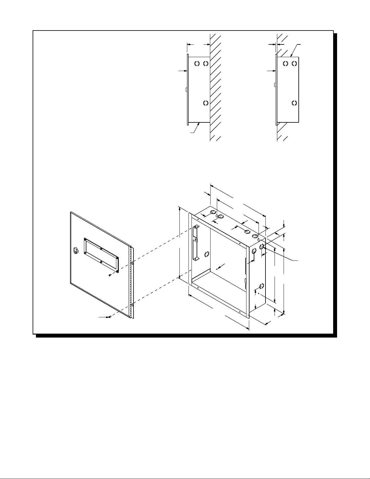
Fig.2: FW-C4EZ Enclosure Installation and Dimensions
MATERIAL: BACKBOX 18GA (0.048") THICK
DOOR 16GA (0.059") THICK
COLD ROLLED STEEL
FINISH: PAINTED
DOOR
DOOR
BACKBOX
5
-
16
16
1
"
-
5
4
SURFACE
(SIDE VIEW)
3
"
-
1
4
"
5
"
-
16
DOOR
WALL WALL
(SIDE VIEW)
1
"
-
14
2
11
"
2
"
1
"
7
"
-
DIA.
32
HOLE
BACKBOX
1
2
"
12
3
"
-
4
1
-
2
FLUSH
1
-
1
2
"
7
"
-
14
8
BACKBOX
"
1
"&"
-
1
8
KNOCKOUT
7
-
8
#6 x 5/16" SCREW
Page 9 of 36
3
"
-
4
8
7
"
-
15
8
3
"
-
1
8
5
"
Page 10
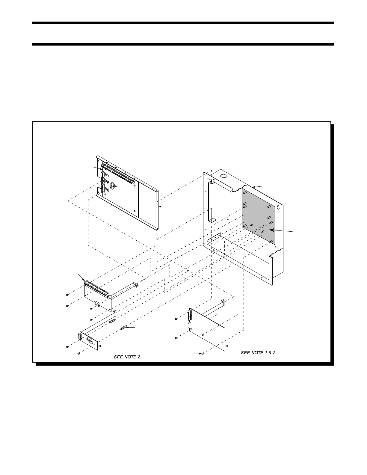
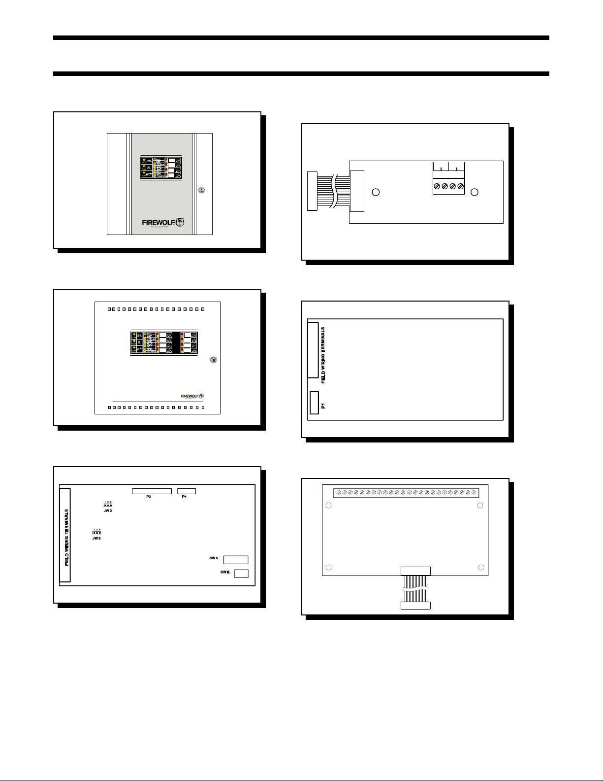
5.0 MODULE MOUNTING LOCATIONS
The FW-C2Z, FW-C4Z and FW-C4EZ fire alarms come pre-assembled with all components and boards, except for Adder Modules.
Module installation locations are shown below.
Be sure to connect a solid Earth Ground (from building system ground / to a cold water pipe) to the Chassis Earth Ground Mounting
Lug, and to connect the Earth Ground Wire Lugs from the Main Chassis to the ground screw on the Backbox.
Note that a CH-429 Accessory Mounting Plate is required for the FW-C2Z, or FW-C4Z if any Adder Module is to be used. Note that
only one of FW-RB4, FW-RB8, FW-RPM, or FW-DACT Modules may be used. The CH-429 is installed so that the one Module being
used is towards the bottom of the enclosure.
Fig.3: FW-C2Z, FW-C4Z Module Mounting Locations
NOTES:
1. THE CH-429 ACCESSORY MOUNTING PLATE MUST BE INSTALLED SO THAT THE MODULE BEING USED IS
INSTALLED TOWARDS THE BOTTOM OF THE ENCLOSURE. THIS IS AS SHOWN FOR THE FW-DACT OR FW-RPM
AND ROTATED 180 DEGREES FOR THE FW-RB4 OR FW-RB8.
2. ONLY ONE OF FW-DACT, FW-RPM, FW-RB4, OR FW-RB8 MAY BE INSTALLED
MAIN FIRE
ALARM MODULE
BACKBOX
DISPLAY PLATE
RELAY MODULE
(NOTE 1 & 2)
#6-32 x 7/8"
M/F HEX SPACER
POLARITY REVERSAL AND
CITY TIE MODULE
(MODEL FW-RPM)
#6-32 x 1/4"
SCREW
DIALER MODULE
(MODEL FW-DACT)
CH-429
ACC. MOUNTING
PLATE
Page 10 of 36
Page 11
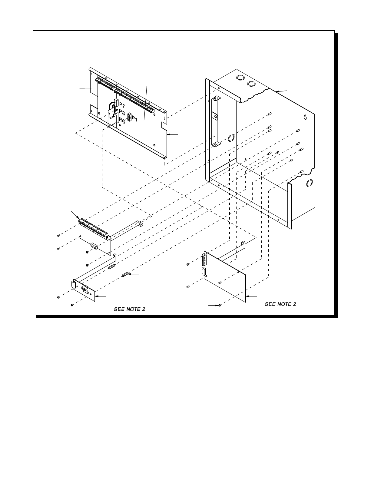
Fig.4: FW-C4EZ Module Mounting Locations
NOTES:
1. RELAY MODULE MAY BE FW-RB4 OR FW-4B8
2. ONLY ONE OF FW-DACT OR FW-RPM MAY BE INSTALLED
MAIN FIRE
ALARM
ZONE ADDER
MODULE
(FW-EZM4)
MODULE
BACKBOX
DISPLAY
PLATE
RELAY MODULE
(NOTE 1)
#6-32 x 7/8"
M/F HEX SPACER
POLARITY REVERSAL AND
CITY TIE MODULE
(MODEL FW-RPM)
#6-32 x 1/4"
SCREW
DIALER MODULE
(MODEL FW-DACT)
Page 11 of 36
Page 12

6.0 MODULE SETTINGS
6.1 MAIN FIRE ALARM MODULE
Class A / B Selection: On the FW-C2Z, FW-C4Z and FW-C4EZ only, JW1 & JW2 are connected from 1 to 2 for Initiating Circuit Class B
Zone Adder Module: On an FW-C4EZ only, remove the jumper on JW4 if a FW-EZM4 Zone Expansion is installed. The Zone Adder
Relay Module: Remove the jumper on JW3 if an FW-RB4 or FW-RB8 Relay Module is installed. The Relay Module is plugged into
Digital Communicator: Remove the jumper on JW6 if a FW-DACT Digital Communicator is installed. The Digital Communicator is plugged
City Tie: Remove the jumper on JW6 if a FW-RPM City Tie is installed. The City Tie is plugged into P8.
Battery: Connected to P2(+’ve) & P3(-’ve) via the factory installed cables.
Transformer: Factory wired to P4 & P5, do not disconnect.
JW5 There should be no jumper here; do not use.
SW9,11,13 Configuration DIP Switches.
Battery Fuse F1: Replace with 10 Amp, 1-1/4" Fast Acting Fuse
(Style B) operation, and from 2 to 3 for Class A (Style D) operation. JW2 is present on the FW-C2Z. Note that
the Class A/B selection affects all Initiating Circuits, and must be used with the correct Configuration DIP
Switch Setting.
Module is plugged into P6 & P7.
P1.
into P8.
Fig.5: Main Fire Alarm Module
FIELD WIRING TERMINALS
JW2
1
2
3
F1
10 AMP
BATTERY
FUSE
P7
23 1
JW1
MAIN FIRE ALARM BOARD
P8
P6
JW4
JW3
P1
SW13
SW11
SW9
JW6
JW5
BATT+
BATT-
XMFR
XMFR
P2
P3
P4
P5
Page 12 of 36
Page 13

6.2 ZONE EXPANSION MODULE (Model FW-EZM4)
Fig.6: FW-EZM4 Zone Expansion Module
Class A / B Selection: JW2 & JW3
are connected from 1 to 2 for Initiating
Circuit Class B (Style B) operation, and
from 2 to 3 for Class A (Style D)
operation. Note that the Class A/B
selection affects all Initiating
Circuits, and must be used with the
correct Configuration DIP Switch
Setting.
P1 & P2: Connections to P7 & P6
respectively on the Main Fire
Alarm Board.
SW5,6 Config DIP Switches.
6.3 RELAY MODULES (Models FW-RB4 or FW-RB8)
Fig.7: FW-RB4 or FW-RB8 Relay Module
P1 Connect to P1 on the Main
Fire Alarm Board.
By the factory setting, the 4 or 8 relays
are controlled by Initiating Circuits 1 to
8 respectively. This is configured by
selecting ...
JW1 Initiating Circuit #1 controls
Relay #1.
JW2 Initiating Circuit #2 controls
Relay #2.
|
|
JW8 Initiating Circuit #8 controls
Relay #8.
Alternately, each relay may be set as
a Common Alarm or Common
Supervisory Relay by removing the
jumper from JW1 to JW1A, etc. These
jumpers have two positions to select
Alarm or Supervisory each.
P1
JW1A Alarm or Supv. control for
JW2A Alarm or Supv. control for
JW8A Alarm or Supv. control for Relay #8.
Finally, there are jumpers JW1.2, JW2.3, up to JW7.8 that allow a relay to have the same control as an adjacent relay. For example, starting with
the factory default setting, moving the jumper from JW2 to JW1.2 will make both Relays 1 & 2 operate with Initiating Circuit #1.
Relay #1.
Relay #2.
|
|
Page 13 of 36
Page 14

6.4 DACT / Dialer MODULE (Model FW-DACT)
Fig.8: FW-DACT Dialer Module
P1 Cable to P8 on the Main Fire
Alarm Board.
Jumper JW6 on the Main Fire Alarm
Module must be removed if a FW-
DACT is installed. Note that this
module cannot be installed if a City Tie
Module is used.
Please see LT-639NAP, the FW-DACT
Manual for more information.
6.5 POLARITY REVERSAL and CITY TIE MODULE (MODEL: FW-RPM)
P1 Cable to P8 on the Main Fire Alarm
Module.
JW1 Cut this jumper for Trouble transmi ssion.
When this jumper is cut and a system
trouble occur, the designated terminals
will transmit a "zero volts" or "open"
circuit. Please note that at normal
condition, the terminals polarity is read
exactly as labelled on the circuit board.
Jumper JW6 on the Main Fire Alarm Module
must be removed if a City Tie Module is
installed. Note that this module cannot be
installed if a FW-DACT / Dialer Module is
used.
Fig.9: FW-RPM City Tie Module
Page 14 of 36
Page 15

7.0 FIELD WIRING
7.1 GENERAL FIELD WIRING CONSIDERATIONS
Because most of the Field Wiring is to the Main Board on the swinging DeadFront, it is very important to properly dress
the wires so as not to place stress on either their connection to the boards, or running to conduit. The Figure below
shows the required wiring techniques.
Fig.10: General Field Wiring Considerations
USE AT LEAST
3 WIRE TIES
AS SUPPLIED
THROUGH HOLES
ON DEADFRONT
WIRE TIE
IN 2 PLACES
TO BACK OF
ENCLOSURE
DRESS WIRES NEAR
TOP OF ENCLOSURE
CLEAR OF ADDER
MODULES
Page 15 of 36
Page 16

7.2 MAIN FIRE ALARM MODULE TERMINAL CONNECTIONS
Wire devices to terminals as shown. See wiring tables and Appendix A for compatible devices and Appendix C for specifications.
Caution: Do not exceed power supply ratings: FW-C2Z, FW-C4Z, total current for Notification Circuits is 2.4 A max.
FW-C4EZ, total current for Notification Circuits is 5 A max.
Fig.11: Main Fire Alarm Module Terminal Connections
Page 16 of 36
Page 17

Fig.11a:Main Fire Alarm Module Terminal Connections (continued)
EXAMPLES OF BOTH CLASS “A” AND “B” WIRING ARE SHOWN, BUT
ONLY ONE CLASS OF WIRING MAY BE USED IN ANY INSTALLATION.
Page 17 of 36
Page 18

7.3 ZONE EXPANSION MODULE (FW-EZM4) TERMINAL CONNECTIONS
Wire devices to terminals as shown. See wiring tables and appendix "A" for compatible devices. See appendix "C" for Module specifications.
Fig.12: FW-EZM4 Zone Expansion Module Terminal Connections
EXAMPLES OF BOTH CLASS “A” AND “B” WIRING ARE SHOWN, BUT
ONLY ONE CLASS OF WIRING MAY BE USED IN ANY INSTALLATION.
EXAMPLES OF BOTH CLASS “A” AND “B” WIRING ARE SHOWN, BUT
ONLY ONE CLASS OF WIRING MAY BE USED IN ANY INSTALLATION.
Page 18 of 36
Page 19

7.4 RELAY MODULE ( FW-RB4 or FW-RB8) TERMINAL CONNECTIONS
Note that only Relays #1 to #4 are present on the FW-RB4.
Fig.13: FW-RB4 / FW-RB8 Relay Terminal Connections
Page 19 of 36
Page 20

7.5 DACT / Dialer MODULE (FW-DACT) TERMINAL CONNECTIONS
See the FW-DACT Manual (LT-639NAP) for connection information.
7.6 POLARITY REVERSAL and CITY TIE MODULE (MODEL: FW-RPM) TERMINAL CONNECTIONS
See Appendix for Module specifications. Wire as shown using proper wire gauges.
Note that for use in the USA, the installer MUST add an Atlantic Scientific (Tel. 407-725-8000) Model #24544 Protective Device, or
similar ULI-Listed QVRG Secondary Protector, as shown.
Note: The Terminal Blocks are “depluggable” for ease of wiring.
The City Tie Interface is Not Power Limited.
Either the FW-RPM’s City Tie or Reverse Polarity Interface may be used, but not both.
Fig.14: FW-RPM Polarity Reversal and City Tie Module Terminal Connections
Page 20 of 36
Page 21

7.7 POWER SUPPLY CONNECTIONS
The power supply is part of the Main Fire Alarm Module and the Chassis. The ratings are:
Model FW-C2Z, FW-C4Z:
Model FW-C4EZ:
Electrical input ratings: 120 VAC, 60 Hz, 2.0A (Uses 3A in line time delay fuse)
Power supply total current: 2.75 A maximum
Battery Fuse on Main Module: F1: Replace with 10 Amp, 1-1/4" Fast Acting Fuse
Electrical input ratings: 120 VAC, 60 Hz, 2.5A (Uses a 4.0A circuit breaker)
Power supply total current: 6 A maximum
Battery Fuse on Main Module: F1: Replace with 10 Amp, 1-1/4" Fast Acting Fuse
CAUTION: Do not exceed power supply ratings.
See appendix "C" for specifications. Wire as shown using proper wire gauges.
Fig.15: Power Supply Connections
Page 21 of 36
Page 22

7.8 WIRING TABLES
Fig.16: WIRING TABLE FOR INITIATING CIRCUITS
WIRE GAUGE MAXIMUM WIRING RUN TO LAST DEVICE (ELR)
(AWG) ft m
22 2990 910
20 4760 1450
18 7560 2300
16 12000 3600
14 19000 5800
12 30400 9200
NOTE : MAXIMUM LOOP RESISTANCE SHOULD NOT EXCEED 100 OHMS
Fig.17: WIRING TABLE FOR Notification Circuits
TOTAL MAXIMUM WIRING RUN TO LAST DEVICE (ELR) MAX. LOOP
SIGNAL LOAD RESISTANCE
Amperes ft m ft m ft m ft m Ohms
0.06 2350 716 3750 1143 6000 1829 8500 2591 30
0.12 1180 360 1850 567 3000 915 4250 1296 15
0.30 470 143 750 229 1200 366 1900 579 6
0.60 235 71 375 114 600 183 850 259 3
0.90 156 47 250 76 400 122 570 174 2
1.20 118 36 185 56 300 91 425 129 1.5
1.50 94 29 150 46 240 73 343 105 1.2
1.70 78 24 125 38 200 61 285 87 1.0
RS-485 WIRING: See the Connection Diagram.
4-WIRE SMOKE WIRING: The maximum allowable current is 0.15 Amperes. The maximum allowed Voltage Drop
18AWG 16AWG 14AWG 12AWG
is 1 Volt. Refer to the Indicating Circuit Wiring Table above.
Page 22 of 36
Page 23

8.0 SYSTEM CHECKOUT
8.1 BEFORE TURNING THE POWER "ON":
1. To prevent sparking, do not connect the batteries. Connect the batteries after powering the system from the main
AC supply.
2. Check that all Modules are installed in the proper location with the proper connections.
3. Check all field (external) wiring for opens, shorts, and ground.
4. Check that all interconnection cables are secure, and that all connectors are plugged-in properly.
6. Check all Jumpers and Switches for proper setting.
7. Check the AC power wiring for proper connection.
8. Check that the chassis is connected to EARTH GROUND (cold water pipe).
9. Make sure to close the front cover plate before powering the system from main AC supply.
8.2 POWER-UP PROCEDURE:
1. After completing the System Checkout procedures, power-up the panel. The "AC-ON" green LED should illuminate,
the “Common Trouble” LED should illuminate, and the buzzer should sound. Press the “System Reset” button.
2. Since the batteries are not connected, the "Battery Trouble" LED should illuminate, and the buzzer should sound
intermittently and the Common Trouble LED should flash.
3. Connect the batteries while observing correct polarity; the red wire is positive (+) and black wire is negative (-).
4. All indicators should extinguish except for normal power "AC-ON" green LED.
5. Configure the Fire Alarm Control Panel as described in the Configuration section.
8.3 TROUBLESHOOTING:
Circuit Trouble Normally when a Circuit trouble occurs, its designated trouble indicator will be illuminated, as
well as the Common Trouble Indicator and the Buzzer. To correct the fault, check for open
wiring on that particular Circuit loop or if the Circuit Disconnect Switch is on. Please note:
Disconnecting a Circuit will cause a system trouble (off-normal position).
Remote Fail A Remote Trouble will be indicated on the main panel display for any failure reported by, or
failure to communicate with a Remote Annunciator, FW-DACT, or FW-RPM.
Ground Fault This panel has a common ground fault detector. To correct the fault, check for any external
wiring touching the chassis or other Earth Ground connection.
Battery Trouble Check for the presence of batteries and their conditions. Low voltage (below 20.4V) will cause
a battery trouble. If battery trouble condition persists, replace batteries as soon as possible.
Page 23 of 36
Page 24

9.0 INDICATORS, CONTROLS, & OPERATION
Refer to the following LED Indicators and Control Switch locations ...
Fig.18: Indicators and Control Location
Page 24 of 36
Page 25

9.1 INDICATORS:
Buzzer:
The Buzzer is activated by any of the following ...
Fire Alarm - Steady
Supervisory Alarm - Steady
Trouble - On and off at a rate of 20 per minute.
If the Buzzer is turned on in response to a Non-Latching Trouble or Supervisory, it will be turned off if the condition causing it goes away and there
is no other reason for it to be on.
AC On LED:
The AC On Indicator is activated steady green while the main AC power is within acceptable levels. It is turned off when the level falls below the
power-fail threshold and the panel is switched to standby (battery) power.
Common Alarm LED:
The Common Alarm Indicator turns on steady red whenever the Panel is in Alarm as a result of an alarm on any Initiating Circuit. Since all
Alarms are latched until the Panel is reset, the Indicator will remain on until reset.
Common Supervisory LED (FW-C4Z or FW-C4EZ only):
The Common Supervisory Indicator turns on steady amber when there is a Supervisory Alarm in the Panel, as the result of any Latching or NonLatching Supervisory Circuit. The Indicator is turned off if all Non-Latching Supervisory Circuits are restored and there are no Latching Supervisory
Circuits active. Latching Supervisory Alarms remain active until the Panel is reset.
Common Trouble LED:
The Common Trouble Indicator flashes Amber (at 20 flashes per minute) when there is any Trouble condition being detected on the panel. It
is turned off when all Non-Latching Troubles are cleared.
Remote Trouble LED (FW-C4Z or FW-C4EZ only):
The Remote Failure Indicator is steady Amber if there is trouble detected at a City Tie or Dialer Module, or if there is communication trouble
detected with a Remote Annunciator or if a Remote Annunciator reports a local trouble. It is turned off if these conditions go away.
Fire Drill LED:
The Fire Drill Indicator turns on steady Amber while Fire Drill is active.
Auxiliary Disconnect LED:
The Auxiliary Disconnect Indicator is flashed Amber (20 flashes per minute) when the Auxiliary Disconnect switch is activated. It is turned off
when the switch is activated a second time. When on, it indicates that Common Alarm and Common Supervisory Relays, and any FW-RB4
/ FW-RB8 Relays are not activated. The Trouble Relay is activated. Dialer or City Tie Modules are also inactive if installed, except that a Trouble
condition is transmitted.
Signal Silence LED:
The Signal Silence indicator is flashed Amber (20 flashes per minute) when Indication Circuits are Silenced either by the Signal Silence switch,
or by the Auto Signal Silence Timer. It is turned off when the Signals are re-sounded by a subsequent Alarm.
Battery Trouble LED:
The Battery Trouble Indicator is steady Amber when the Battery is either low (below 20.4 VDC), or disconnected.
Ground Fault LED:
The Ground Fault Indicator is Amber when the Ground Fault Detector detects a Ground Fault on any field wiring. It is turned off when the Ground
Fault is cleared.
Test LED:
Indicates steady Amber when the Fire Alarm Panel is in Walk Test Mode.
Circuit Status LED’s:
These LED’s indicate the Status of Initiating Circuits. They illuminate ...
Alarm : Steady Red
Alarm Verification or Waterflow Retard in Progress : Fast Flashing Red (120 flashes per minute)
Pending Alarm (see Circuit Disconnect Controls) : Fast Flashing Red (120 flashes per minute)
Supervisory : Steady Amber
Circuit Trouble LED’s:
These LED’s indicate Trouble for Initiating and Notification Circuits. They illuminate Slow Flashing Amber (20 flashes per minute) for any field
wiring fault, or if the circuit has been Disconnected.
Page 25 of 36
Page 26

9.2 CONTROLS:
System Reset Switch:
The System Reset momentary switch causes the Fire Alarm Control Panel, and all Circuits, to be reset ...
Resets all Latching Trouble Conditions Resets all Initiating Circuits
Resets the 4-Wire Smoke Supplies Turns off all Notification Circuits
Turns off Signal Silence Indicator Turns off Fire Drill
Stops and resets all Timers Processes inputs as new events
Aux Disconnect not affected
Signal Silence Switch:
Activation of the Signal Silence momentary switch when the Panel is in Alarm turns on the Signal Silence Indicator and deactivates any
Silenceable Notification Circuits. Non-Silenceable Circuits are unaffected. Signals will re-sound upon any subsequent Alarm. This switch does
not function during any configured Signal Silence Inhibit Timer period. It also does not function if the Notification Circuits are active as the result
of a Fire Drill.
Fire Drill Switch:
The Fire Drill momentary switch activates all non-Disconnected Notification Circuits, but does not transmit any Alarms via the Dialer, City Tie,
or Common Alarm Relay, nor are any FW-RB4 or FW-RB8 Relays activated. Fire Drill is cancelled by activating the switch again, or if the Panel
goes into a real Alarm.
Auxiliary Disconnect Switch:
Activating the Auxiliary Disconnect momentary switch activates the Auxiliary Disconnect function. Activating the switch again de-activates the
function. When Auxiliary Disconnect is active, Common Alarm and Common Supervisory Relays, and any FW-RB4 / FW-RB8 Relays are not
activated. The Trouble Relay is activated. Dialer or City Tie Modules are also inactive if installed, except that a Trouble condition is transmitted.
Lamp Test Switch:
Activation of the Lamp Test momentary switch turns all front panel Indicators and the buzzer on.
Buzzer Silence Switch:
Activation of the Buzzer Silence momentary switch while the Buzzer is sounding silences the Buzzer. The Buzzer will resound if there is a
subsequent event.
Circuit Disconnect Switches:
Activation of these non-momentary switches disconnects the respective Initiating Circuit, and causes a Circuit Trouble for that Initiating Circuit
while active. If the disconnect switch is turned off (to its normal position) while there is an Alarm condition in that circuit, the respective circuit
Status LED will flash at a rate of 120 flashes per minute to indicate a Pending Alarm, for 5 seconds. If the disconnect switch is not turned back
on, an Alarm will be processed normally.
9.3 OPERATION:
All Alarm inputs are treated in a similar manner. Alarm inputs include Non-Verified or Verified Alarms, and Water-flow
Alarms. Any of these Alarm inputs occurring when the Panel is not already in Alarm cause the following:
Ž The Buzzer sounds steadily
Ž If Fire Drill is active, it is cancelled
Ž The Common Alarm Indicator turns on
Ž The Common Alarm Relay activates if Aux Disconnect is not active
Ž The Auto Signal Silence Timer, if configured, starts
Ž The Signal Silence Inhibit Timer, if configured, starts
Ž FW-RB4 / FW-RB8 Relays are activated as configured, provided that Aux Disconnect is not active
Ž Signals and Strobes are activated
Subsequent Alarms when the Panel is already in Alarm, cause the following:
Ž The Buzzer sounds steadily
Ž If Signals have been silenced as a result of the Signal Silence button or the Auto Signal Silence Timer, Signals are resounded as they were before
Signal Silence, the Signal Silence Indicator is turned off, and the Auto Signal Silence Timer, if configured, is restarted
Ž Signals and Strobes are activated
Page 26 of 36
Page 27

9.4 CIRCUIT TYPES:
“Circuits” refers to an actual electrical interface, either Initiating (Detection) or Indicating (Signal). “Zone” is a
logical concept for a Fire Alarm Protected Area, and will consist of at least one Circuit. Often the terms Zone and Circuit
are used interchangeably, but in this Manual the term Circuit is used.
Initiating (Detection) Circuit Types:
Non-Verified Alarm = This is a “Normal” type of Alarm which may have Pull-Stations, Smoke Detectors, or Heat Detectors attached.
Verified Alarm = These Alarms are verified by a reset and timing procedure, and may have Pull-Stations, Smoke Detectors, or
Water-Flow Alarm = For Water-flow Sensors (Circuits 3 & 7 on FW-C4Z / FW-C4EZ only). These alarms are identical to normal Non-
Non-Latching Supervisory = For Supervisory Devices (Circuits 4 & 8 on FW-C4Z / FW-C4EZ only). An activation on these circuits will cause
Latching Supervisory = For Supervisory Devices (Circuits 4 & 8 on FW-C4Z / FW-C4EZ only). An activation on these circuits will cause
Any activation of these devices will immediately result in an Alarm condition in the Fire Alarm Control Panel. An
Alarm condition causes the associated Circuit Status LED and the Common Alarm LED to illuminate Red.
Heat Detectors attached. Any activation of Pull-Stations or Heat Detectors will result in an Alarm condition in the
Fire Alarm Control Panel within 4 seconds. Smoke Detectors will be verified for a real Alarm within 60 seconds
depending upon the startup time of the Smoke Detectors being used. If 4 seconds is too long a response time
for Pull-Stations, then they should be wired separately on a Non-Verified Alarm Circuit. An Alarm condition
causes the associated Circuit Status LED and the Common Alarm LED to illuminate Red.
Verified Alarms except that Notification Circuits are Non-Silenceable. Water-Flow Retard Operation is enabled
if “Verified” is selected. With Retard active, these circuits are sampled every one second; if 10 samples are active
within any 15 second interval, the Water-Flow Alarm is confirmed and processed. An Alarm condition causes
the associated Circuit Status LED and the Common Alarm LED to illuminate Red. Note: Do not use Retard
Operation with any external Retarding device; maximum Retard may not exceed 120 seconds.
the Circuit Status LED and the Common Supervisory LED to illuminate Amber. The buzzer will sound
continuously. If the circuit activation is removed, the Supervisory condition will clear (so long as there are no other
Supervisory conditions in the system) and the Circuit Status LED will extinguish.
the Circuit Status LED and the Common Supervisory LED to illuminate Amber. The buzzer will sound
continuously. If the circuit activation is removed, the Supervisory condition will NOT clear.
Indicating (Signal) Circuits Types:
Silenceable Audible = For audible devices such as bells and piezo mini-horns that may be silenced either manually or automatically.
Non-Silenceable Audible = For audible devices such as bells and piezo mini-horns that may not be silenced either manually or
Silenceable Visual = For visual devices such as strobes that use no code pattern (they are continuous).
Non-Silenceable Visual = Same as previous, but is non-silenceable.
The possible Audible Signal Codes are ...
Continuous: •••••••••••• [On 100% of the time]
Temporal Code: ••• ••• ••• [3 of .5 second on, .5 second off, 1.5 second pause]
March Code: • • • • • • • [.5 second on, .5 second off]
California Code: •••• •••• [5 second on, 10 second off]
While sounding, these follow the pattern appropriate for the condition; the configured Evacuation Code (default
is Temporal Code) during Single-Stage Alarm, or Two-Stage General Alarm, or the Alert Code during Two-Stage’s
Alert (First) Stage.
automatically. While sounding, these follow the pattern appropriate for the condition; the configured Evacuation
Code (default is Temporal Code) during Single-Stage Alarm, or Two-Stage General Alarm, or the Alert Code
during Two-Stage’s Alert (First) Stage.
Page 27 of 36
Page 28

10.0 SYSTEM CONFIGURATION
Configuration of the FW-C2Z, FW-C4Z and FW-C4EZ is accomplished simply by DIP Switch and Jumper Settings.
For DIP Switches, 0 = switch “off”, 1 = Switch “on’). On the Main Fire Alarm Board ...
Function DIP Switch Switch “Off” Switch “On”
Indicating Circuit #1
Audible Device (Bell) Only
Indicating Circuit #2
Audible or Visual Device
# Remote Annunciators
Manual Signal Silence Switch 13, #6 Disabled Enabled
Fire Drill Switch 13, #7 Disabled Enabled
Aux. Disconnect Switch 13, #8 Disabled Enabled
Initiating Circuit #1
Alarm Only
Initiating Circuit #2
Alarm Only
Initiating Circuit #3
Alarm or Waterflow
Initiating Circuit #4 Switch 11, #6 Alarm Supervisory
Alarm or Supervisory
Not Used Switch 11, #8 ----------------- -----------------
Signal Code
Auto Signal Silence
Signal Silence Inhibit Switch 9, #5 None 1 Minute
Initiating Circuit Style / Class Switch 9, #6 Class B (Style B) Class A (Style D)
Aux. Devices Switch 9, #7 Non-Silenceable Silenceable
AC Power Fail Delay to 24 Hour Standby 60 Hour Standby
Aux. Devices Standard Standard
Switch 13, #1 Silenceable Non-Silenceable
Switch 13, #2 Silenceable Non-Silenceable
Switch 13, #3 Audible Device (Bell) Visual Device (Strobe)
Switch 13, #4
Switch 13, #5
Switch 11, #1 Normal Alarm Verified Alarm
Switch 11, #2 Normal Alarm Verified Alarm
Switch 11, #3 Normal Verified Alarm / Retarded Waterflow
Switch 11, #4 Alarm Waterflow
Switch 11, #5 Normal Verified Alarm (no effect on Supv.)
Switch 11, #7
Switch 9, #1
Switch 9, #2
Switch 9, #3
Switch 9, #4
Switch 9, #8
5 off, 4 off = None 5 off, 4 on = One
5 on, 4 off = Two 5 on, 4 on = Three
Non-Latching Supervisory Latching Supervisory
(No effect on Alarm) (No effect on Alarm)
2 off, 1 off = Temporal Code 2 off, 1 on = Continuous
2 on, 1 off = March Time 2 on, 1 on = California Code
4 off, 3 off = Disabled 4 off, 3 on = 5 Minutes
4 on, 3 off = 10 Minutes 4 on, 3 on = 20 Minutes
Notes:
& After any Configuration Switches are changed, it is necessary to perform a System Reset !!
& Only Indicating Circuit 2 may be configured for Visual Devices.
& If Initiating Circuit 3 is configured as Waterflow, the corresponding Verified selection becomes a Retard selection.
Note: Do not use Retard Operation with any external Retarding device; maximum Retard may not exceed 120 seconds.
& If Initiating Circuit 4 is configured as Alarm, the corresponding Latching selection has no effect.
& If Initiating Circuit 4 is configured as Supervisory, the corresponding Verified selection has no effect.
& The selection of Class A/B (Style Z/Y) Notification Circuits is only a matter of how they are wired. See Connection
Info.
& If Class A (Style D) Initiating Circuits are selected (FW-C2Z, FW-C4Z, FW-C4EZ only), the appropriate Board
Jumpers must also be set. Class B Initiating Circuits 1&2 combine to create Class A Circuit #1, and Class B
Initiating Circuits 3&4 combine to create Class A Circuit #2. DIP Switches for Circuits 3&4 are ignored except for
an FW-C4EZ with a FW-EZM4 Expansion. LED Indicators for Circuits 3&4 are non-functional except for an FWC4EZ with a FW-EZM4 Expansion.
Page 28 of 36
Page 29

On the FW-EZM4 Zone Expansion Module ...
Function DIP Switch Switch “Off” Switch “On”
Indicating Circuit #3
Audible Device (Bell) Only
Indicating Circuit #4
Audible or Visual Device
Not Used Switch 6, #4 ----------------- -----------------
Initiating Circuit #5
Alarm Only
Initiating Circuit #6
Alarm Only
Initiating Circuit #7
Alarm or Waterflow
Initiating Circuit #8 Switch 5, #6 Alarm Supervisory
Alarm or Supervisory
Not Used Switch 5, #8 ----------------- -----------------
Switch 6, #1 Silenceable Non-Silenceable
Switch 6, #2 Silenceable Non-Silenceable
Switch 6, #3 Audible Device (Bell) Visual Device (Strobe)
Switch 5, #1 Normal Alarm Verified Alarm
Switch 5, #2 Normal Alarm Verified Alarm
Switch 5, #3 Normal Verified Alarm / Retarded Waterflow
Switch 5, #4 Alarm Waterflow
Switch 5, #5 Normal Verified Alarm (no effect on Supv.)
Switch 5, #7
Non-Latching Supervisory Latching Supervisory
(No effect on Alarm) (No effect on Alarm)
Notes:
& After any Configuration Switches are changed, it is necessary to perform a System Reset !!
& Only Indicating Circuit 4 may be configured for Visual Devices.
& If Initiating Circuit 7 is configured as Waterflow, the corresponding Verified selection becomes a Retard selection.
Note: Do not use Retard Operation with any external Retarding device; maximum Retard may not exceed 120 seconds.
& If Initiating Circuit 8 is configured as Alarm, the corresponding Latching selection has no effect.
& If Initiating Circuit 8 is configured as Supervisory, the corresponding Verified selection has no effect.
& The selection of Class A/B (Style Z/Y) Notification Circuits is only a matter of how they are wired. See Connection
Info.
& If Class A (Style D) Initiating Circuits are selected the appropriate Board Jumpers must also be set. Class B
Initiating Circuits 5&6 combine to create Class A Circuit #3, and Class B Initiating Circuits 7&8 combine to create
Class A Circuit #4. DIP Switches for Circuits 5 to 8 are ignored, and LED Indicators for Circuits 5 to 8 are nonfunctional.
Page 29 of 36
Page 30

11.0 WALK TEST OPERATION
Walk-Test allows an installer to verify the Initiating Circuit wiring in a system. Walk-Test is entered by pressing and
holding the Buzzer Silence and Lamp Test Momentary Switches for at least 5 seconds. Circuits to be tested are
identified using the Circuit Disconnect Slide Switches. Activation of any Initiating Circuit which has been selected for
Walk-Test will cause the Audible Notification Circuits to activate briefly for a number of short bursts corresponding to
the Circuit number. Any subsequent activations on the same Initiating Circuit will activate the Audible Indicating Circuit
only once. If another Initiating Circuit is activated then the Audible Notification Circuits will activate for a number of short
bursts corresponding to the Circuit number of the new zone being walk-tested, and so on.
If Initiating Circuit #3 is first activated, the Indication Circuits will sound for three bursts, with additional activations
sounding for one burst, etc. The initial burst interval denoting the count of the Circuit number is one second on half
a second off. The subsequent burst interval denoting additional activations on the same Initiating Circuit is one half
second on then off. After the sounding pattern has been sent on the Notification Circuits, the Initiating Circuit is reset
and tested again. If it is still active (in alarm) the pattern will be re-sent. Trouble on any Initiating Circuit selected for
Walk-Test causes the Notification Circuits to be activated continuously for 5 seconds.
Alarm Verification and Water-flow Alarm Retard Operations are disabled on Circuits being Walk-Tested. All Circuits
not selected for Walk-Test continue to function normally. Walk-Test operation is disabled if the Fire Alarm Control Panel
is in Alarm or goes into Alarm while Walk-Test is active. It will also time-out after 60 minutes of no activity.
Page 30 of 36
Page 31

APPENDIX "A" - COMPATIBLE DEVICES
UNDERWRITER’S LABS CANADA (ULC)
CANADIAN: 2-WIRE SMOKE DETECTOR CONTROL PANEL COMPATIBILITY
NOTES:
Whether mixing different models of compatible smoke detectors, or using the same model on the same Circuit, total
standby current of all detectors must not exceed 3 mA.
SMOKE DETECTOR
MAKE MODEL / BASE MAKE MODEL / BASE MAKE MODEL / BASE
HOCHIKI EDWARDS FENWAL
DCD -135/NS6-220 6249C PSD-7131 / 70-201000-001
DCD-135/NS4-220 6250C PSD-7131 / 70-201000-002
DCD-135/HSC-220R 6264C PSD-7131 / 70-201000-003
DCD-190/NS6-220 6266C PSD-7131 / 70-201000-005
DCD-190/NS4-220 6269C PSD-7130 / 70-201000-001
DCD-190/HSC-220R 6270C PSD-7130 / 70-201000-002
SIJ-24/NS6-220 6269C-003 PSD-7130 / 70-201000-003
SIJ-24/NS4-220 6270C-003 PSD-7130 / 70-201000-005
SIJ-24/HSC-220R PSD-7128 / 70-201000-001
SLR-24/NS6-220 CERBERUS PYROTRONICS PSD-7126 / 70-201000-002
SLR-24/NS4-220 D1-2 PSD-7126 / 70-201000-003
SLR-24/HSC-220R D1-3 / DB-3S PSD-7126 / 70-201000-005
SLR-24H/NS6-220 PSD-7129 / 70-211002-000
SLR-24H/NS4-220 MIRCOM PSD-7125 / 70-201000-001
SLR-24H/HSC-220R MIR-525 PSD-7126 / 70-201000-002
SLR-835/NS6-220 MIR-525T PSD-7125 / 70-201000-003
SLR-835/NS4-220 PSD-7125 / 70-201000-005
SLR-835/HSC-220R MIRTONE CPD-7021 / 70-201000-001
SLR-835B-2 73471 CPD-7021 / 70-201000-002
73494 CPD-7021 / 70-201000-003
SYSTEM SENSOR 73575 CPD-7021 / 70-201000-005
1400-A 73495/73486
2400-A 73495/73487 NAPCO
1451-A / B401B 73595/73486 FW-2
1451-A / B406B 73595/73497
2451-A / B401B 73594/73400 SIMPLEX
2451-A / B406B 73405/73400 2098-9110
1451DH / DH400A 73594/73401
2451-A / DH400A 73405/73401
Page 31 of 36
Page 32

UNDERWRITER’S LABS INC. (UL)
UNITED STATES: 2-WIRE SMOKE DETECTOR CONTROL PANEL COMPATIBILITY
NOTES:
1) Whether mixing different models of compatible smoke detectors, or using the same model on the same Circuit, total
standby current of all detectors must not exceed 3 mA.
2). The below listed Smoke Detectors are compatible with Initiating Circuits having Compatibility Identifier "A".
SMOKE DETECTOR COMPATIBILITY RATED SMOKE DETECTOR COMPATIBILITY RATED
MAKE MODEL / IDENTIFIER STANDBY MAKE MODEL / BASE IDENTIFIER STANDBY
BASE HEAD / BASE CURRENT HEAD / BASE CURRENT
HOCHIKI 2451 / B406B A - A 0.12 mA
DCD-190/HSC-220R HD-3/HB-72 0.035mA 2451 / DH400 A - A 0.12 mA
DCD-190/NS6-220 HD-3/HB-3 0.035mA 2451TH / B401 A - A 0.12 mA
DCD-190/NS4-220 HD-3/HB-3 0.035mA 2451TH / B401B A - A 0.12 mA
DCD-135/HSC-220R HD-3/HB-3 0.035mA 2451TH / B406B A - A 0.12 mA
DCD-135/NS6-220 HD-3/HB-3 0.035mA 4451HT / B401 A - A 0.12 mA
DCD-135/NS4-220 HD-3/HB-3 0.035mA 4451HT / B401B A - A 0.12 mA
SIJ-24/HSC-220R HD-3/HB-72 0.040mA 4451HT / B406B A - A 0.12 mA
SIJ-24/NS6-220 HD-3/HB-3 0.040mA 5451 / B401 A - A 0.12 mA
SIJ-24/NS4-220 HD-3/HB-3 0.040mA 5451 / B401B A - A 0.12 mA
SLR-24/HSC-220R HD-3/HB-72 0.045mA 5451 / B406B A - A 0.12 mA
SLR-24/NS6-220 HD-3/HB-3 0.045mA
SLR-24/NS4-220 HD-3/HB-3 0.045mA SENTROL - ESL
SLR-24H/NS6-220 HD-3/HB-3 0.045mA 429C S10A - N/A 0.10 mA
SLR-24H/NS4-220 HD-3/HB-3 0.045mA 429CT S10A - N/A 0.10 mA
SLR-24H/HSC-220R HD-3/HB-72 0.045mA 429CST S11A - N/A 0.10 mA
SLR-835/NS6-220 HD-3/HB-3 0.045mA 429CRT S11A - N/A 0.10 mA
SLR-835/NS4-220 HD-3/HB-3 0.045mA 711U / 701E, 701U, 702E, 702U S10A - S00 0.10 mA
SLR-835/HSC-220R HD-3/HB-72 0.045mA 712U / 701E, 701U, 702E, 702U S10A - S00 0.10 mA
SLR-835B-2 HD-6 55uA @ 24VDC 713-5U / 701E, 701U, 702E, 702U S10A - S00 0.10 mA
713-6U / 701E, 701U, 702E, 702U S10A - S00 0.10 mA
721U / 702E, 702U S10A - S00 0.10 mA
721UT / 702E, 702U S10A - S00 0.10 mA
SYSTEM SENSOR 722U / 702E, 702U S10A - S00 0.10 mA
1100 A - N/A 0.12 mA 731U / 702E, 702U, 702RE, 702RU S11A - S00 0.10 mA
1151 / B110LP A - A 0.12 mA 732U / 702E, 702U, 702RE, 702RU S11A - S00 0.10 mA
1151 / B116LP A - A 0.12 mA
1400 A - N/A 0.10 mA DETECTION SYSTEMS INC.
1451 / B401 A - A 0.12 mA DS250 B - N/A 0.10 mA
1451 / B401B A - A 0.12 mA DS250TH B - N/A 0.10 mA
1451 / B406B A - A 0.12 mA DS282 B - N/A 0.10 mA
1451DH / DH400 A - A 0.12 mA DS282TH B - N/A 0.10 mA
2100 A - N/A 0.12 mA
2100T A - N/A 0.12 mA
2151 / B110LP A - A 0.12 mA MIRCOM
2151 / B116LP A - A 0.12 mA MIR-525U FDT-1 0.10 mA
2400 A - N/A 0.12 mA MIR-525TU FDT-1 0.10 mA
2400TH A - N/A 0.12 mA
2451 / B401 A - A 0.12 mA
2451 / B401B A - A 0.12 mA NAPCO
Page 32 of 36
Page 33

FW-2 HD-6 55uA @ 24VDC
UNDERWRITER’S LABS INC. (UL)
UNITED STATES: 4-WIRE SMOKE DETECTOR CONTROL PANEL COMPATIBILITY
Mircom MIR-545U MIR-545TU
Sentrol - ESL 541C 541CXT 709-MV-21 709-24V-21
741U with 449AT, 449C, 449CT, 449CRT, 449CST, 449CSTE, 449CSRT, 449CSRH, 449CSST,
702U or 702E Base 449CSSTE, 449CTE, 449CLT, 449CSLT
System Sensor 1424 6424 6424A A77-716B
DH400ACDCI DH400ACDCP DH400ACDCIHT
UNDERWRITER’S LABS INC. (UL)
UNITED STATES: SIGNALLING DEVICE CONTROL PANEL COMPATIBILITY
System Sensor SpecrAlert
P2415 P2415W P241575 P241575W P2475
P2475W P24110 P24110W S2415 S2415W
S241575 S241575W S2475 S2475W S24110
S24110W H12/24 H12/24W MDL MDLW
Wheelock
AS-2415W-24-FR AS-241575W-FR AS-2430W-FR AS-2475W-FR AS-24110W-FR
AS-2415C-FW AS-2430C-FW AS-2475C-FW AS-24100C-FW AH-24-R
AH-24-WP-R NS-2415W-FR NS-241575W-FR NS-2430W-FR NS-2475W-FR
NS-24110W-FR NS4-2415W-FR NS4-241575W-FR NS4-2430W-FR NS4-2475W-FR
NS4-24110W-FR RS-2415W-FR RSS-241575W-FR RSS-2415W-FR RSS-241575W-FR
RSS-2430W-FR RSS-2475W-FR RSS-24110W-FR RSS-2415C-FW RSS-2430C-FW
RSS-2475C-FW RSS-24100C-FW MT-12/24-ULC MT-24-LS-VFR-ULC MT-24-WS-VFR-ULC
AMT-12/24-R-ULC AMT-24-LS-VFR-ULC MB-G6-24-R MB-G10-24-R SM-12/24-R
DSM-12/24-R
Gentex
ST24-15 ST24-15/75 ST24-30 ST24-60 ST24-75
ST24-110
HS24-15 HS24-15/75 HS24-30 HS24-60 HS24-75
HS24-110
.
APPENDIX "B" - FW-RB8 REMOTE ANNUNCIATOR
The FW-RB8 Eight Zone Remote Annunciator mounts in an electrical box. It provides annunciation for the FW-C4Z or FWC4EZ’s full complement of 8 Initiating circuits.
Page 33 of 36
Page 34

APPENDIX "C" - MODULE SPECIFICATIONS and FEATURES
Fire Alarm Control Panel (FW-C2Z) Fire Alarm Control Panel (FW-C4EZ)
General: In smaller Enclosure ... General: In larger Enclosure ...
M 1 supervised Style B (Class B) Initiating Circuit; configurable M 4 supervised Style B (Class B) or 2 Style D (Class A) Initiating
(Normal or Verified). [Compatibility ID “A”] Circuits; configurable. [Compatibility ID “A”]
Power Limited: 26VDC, 3 mA standby, 1.5Vp-p ripple, 50 Power Limited: 26VDC, 3 mA standby, 1.5Vp-p ripple, 50
M 2 Style Y/Z (Class A/B) Notification Circuits; configurable as M 2 Style Y/ Z (Class A/B) Notification Circuits; configurable as
strobes or audibles. strobes or audibles.
Power Limited: 24 VDC unfiltered Power Limited: 24 VDC unfiltered
M 2 supervised Style B (Class B) or 1 Style D (Class A) Initiating M One FW-EZM4 Zone Expansion may be added.
Circuits; configurable (Normal or Verified). M Initiating Circuit Disconnect Switches.
[Compatibility ID “A”] M Optional FW-DACT or City Tie Adder.
M Initiating Circuit Disconnect Switch. M Optional FW-RB4 / FW-RB8 Relay Module.
M Optional FW-DACT or City Tie Adder. M Resettable 4-Wire Smoke Detector Power Supply.
M Optional FW-RB4 / FW-RB8 Relay Module. Power Limited: 28VDC, 100mA max, 1.5Vp-p ripple
M Resettable 4-Wire Smoke Detector Power Supply. M Aux Power Supply.
Power Limited: 28VDC, 100mA max, 1.5Vp-p ripple Power Limited: 24VDC, 300mA max, unfiltered
M Aux Power Supply. for RTI or Remote Annunciators
Power Limited: 24VDC, 300mA max, unfiltered M 1 RS-485 Connection for up to 3 FW-RB8 Remote
for RTI or Remote Annunciators Annunciators.
M Auxiliary relays: (resistive loads) M Auxiliary relays: (resistive loads)
Common Alarm: Form C, 1Amp, 28VDC Common Alarm, Supervisory, Trouble
Common Trouble: Form C, 1Amp, 28VDC All are Form C, 1Amp, 28VDC
M Micro-controller Based Design. M Micro-controller Based Design.
M DIP Switch Configurable. M DIP Switch Configurable.
M Walk-Test function. M Walk-Test function.
Electrical ratings: Electrical ratings:
M AC Line Voltage: 102 to 132 VAC. M AC Line Voltage: 102 to 132 VAC.
M Pwr Supp. ratings: 2.75 Amps. max. (secondary) M Pwr Supp. ratings: 6 Amps. max. (secondary)
M For Notification Circuits: 24VDC unfiltered M For Notification Circuits: 24VDC unfiltered
M Battery: 24VDC, Gel-Cell/Sealed Lead-Acid M Battery: 24VDC, Gel-Cell/Sealed Lead-Acid
Charging capability: 4 to 6.5 AH batteries Charging capability: 10 to 24 AH batteries
Fuse on Main Board: 10 Amps. Fuse on Main Board: 10 Amps.
M Current Consumption: Standby: 110 mA, Alarm: 220 mA M Current Consumption: Standby: 110 mA, Alarm: 220 mA
mA max. (alarm) mA max. (alarm)
1.7 A @ 49C per Circuit (2.4 A Total) 1.7 A @ 49C per Circuit (5A Total)
2 Amps (primary, transformer inline fuse) 2.5 Amps (Uses 4A circuit breaker)
2.40 Amps. max. 5 Amps. max.
Fire Alarm Control Panel (FW-C4Z) Zone Expansion Module (FW-EZM4)
General: Same as FW-C2Z, plus ... M May be added to FW-C4EZ.
M 4 supervised Style B (Class B) or 2 Style D (Class A) Initiating M 4 supervised Style B (Class B) or 2 Style D (Class A) Initiating
Circuits; configurable (Normal or Verified, and for Style B there Circuits; configurable. [Compatibility ID “A”]
may be one Waterflow and one Supervisory). Power Limited: 22VDC, 3 mA standby, 1.5Vp-p ripple, 50
[Compatibility ID “A”] mA max. (alarm)
M Optional FW-RB4 or FW-RB8 Relay Module. M 2 Style Y or Z (Class B or A) Notification Circuits; configurable
M 1 RS-485 Connection for up to 3 FW-RB8 Remote as strobes or audibles.
Annunciators. Power Limited: 24 VDC unfiltered, 1.7A @49C per Circuit
M Auxiliary relays: (resistive loads) M Current Consumption: Standby: 45 mA, Alarm: 120 mA
Common Alarm, Supervisory, Trouble
All are Form C, 1Amp, 28VDC 8 Zone Remote Annunciator (FW-RB8)
DACT / Dialer Module (FW-DACT) M Current Consumption: Standby: 35 mA, Alarm: 90 mA
M DACT - “Digital Alarm Communicator Transmitter”
Using Ademco Contact ID and SIA-DCS Protocols.
M Current Consumption: Standby: 45 mA, Alarm: 120 mA
Polarity Reversal and City Tie Module (FW-RPM)
M Supervised City Tie Not Power Limited
24VDC unfiltered, 210 mA max., Trip coil: 14 ohms
M Polarity Reversal Power Limted
24VDC open, 12VDC @ 3.5 mA, 8 mA max. (shorted)
M Current Consumption: Standby: 35 mA, Alarm: 300 mA System Model: SERIES FW-CZ, Fire Alarm Control Panel
Model: FW-RB4 / FW-RB8 Relay Module Protected Premises (using FW-DACT or FW-RPM), Central Station
M Four or Eight Relays: Form C, 1A (resistive), 28 VDC per Protected Premises (using FW-DACT).
contacts Type of Service: A, M, WF, SS (SS is only Local or with DACT)
M Each individual relay can be: Type of Signalling: Non-Coded
Relay per Zone, Common Alarm, Common Supervisory Applicable Standards: NFPA 70 and 72, UL-864, ULC S-524, ULC
M Current Consumption: Standby: 5 mA, Alarm: 160 mA S-527
M RS-485 Interface, up to 3 per FA-200 Panel.
System Type: Local, Auxiliary (using FW-RPM), Remote Station
Page 34 of 36
Page 35

APPENDIX "D" - POWER SUPPLY & BATTERY CALCULATIONS (SELECTION GUIDE)
Use the form below to determine the required Secondary Power Supply (batteries).
IMPORTANT NOTICE
The main AC branch circuit connection for Fire Alarm Control Unit must provide a dedicated continuous power without provision of any disconnect devices.
Use #12 AWG wire with 600-volt insulation and proper over-current circuit protection that complies with the local codes. Refer to appendix "C" for
specifications.
POWER REQUIREMENTS (ALL CURRENTS ARE IN AMPERES)
Model Number Description Qty STANDBY TOTAL ALARM TOTAL
FW-C2Z, Fire Alarm 1 X 0.110 = 0.220 =
FW-C4Z, FW-C4EZ Control Panel
FW-EZM4 Zone Expansion X 0.045 = 0.120 =
FW-RB4 / FW-RB8 Relay Module X 0.005 = 0.160 =
FW-RPM City Tie Module X 0.035 = 0.300 =
FW-DACT DACT / Dialer Module X 0.045 = 0.120 =
FW-RB8 Remote Annunciator X 0.035 = 0.090 =
FW-RTI Remote Trouble Indicator X 0.035 = 0.035 =
2-Wire Smoke Detectors X ' 0.0001 = * 0.090 = 0.090
4-Wire Smoke Detectors X = =
Signal Load (bells, horns, strobes, and etc.) =
Auxiliary Power Supply for Annunciators, etc. = =
Total currents (Add above currents) STANDBY (A) (B)
Total Current Requirement: ALARM (B)______ Amps.
STANDBY ALARM
ALARM
Battery Capacity Requirement:
([STANDBY (A) ______ ] X [(24 or 60 Hours) ___ ]) + ([ALARM (B) ______ ] X [%Alarm in Hr.] _____) = (C) ______AH
Total Alarm Current: Must be 2.75 amperes or less for FW-C2Z, and FW-C4Z. Notification Circuits not to exceed 2.4 amperes.
Battery Selection: Multiply (C) by 1.20 to derate battery.
* Assuming three Initiating Circuits in alarm.
% Use 0.084 for five minutes of alarm as a multiplier figure.
' Using the 1400-A 2-wire smoke detector. See Appendix "A", for other available smoke detectors .
Examples: Configuration 24 Hrs Standby, 5 Min Alarm 60 Hrs Standby, 5 Min Alarm
FW-C2Z/4 Basic 4 AH Batteries Not Possible
FW-C2Z/4, FW-DACT, FW-RB8, RTI 6.5 AH Batteries Not Possible
FW-C4EZ, FW-EZM4 10 AH Batteries 12 AH Batteries
FW-C4EZ, FW-EZM4, FW-DACT, FW-RB8, 3 of FW-RB8 10 AH Batteries 24 AH Batteries
Always use the Selection Guide Chart to verify actual Battery Requirements.
Must be 6 amperes or less for FW-C4EZ. Notification Circuits not to exceed 5 amperes.
Use 6.5AH Batteries for the FW-C2Z, FW-C4Z.
Use 10AH Batteries for the FW-C4EZ.
The FW-C4EZ will charge up to 24AH Batteries if they are in an external Battery Cabinet.
Page 35 of 36
Page 36

WARRANTY
NAPCO SECURITY SYSTEMS, INC. (NAPCO) warrants its products liability concerning its products.
to be free from manufacturing defects in materials and workmanship
for 12 months following the date of manufacture. NAPCO will, within In no event shall NAPCO be liable for an amount in excess of
said period, at its option, repair or replace any product failing to NAPCO’s original selling price of the product, for any loss or damage,
operate correctly without charge to the original purchaser or user. whether direct, indirect, incidental, consequential, or otherwise arising
This warranty shall not apply to any equipment, or any part thereof, set forth, shall not be enlarged, diminished or affected by and no
which has been repaired by others, improperly installed, improperly obligation or liability shall arise or grow out of Seller’s rendering of
used, abused, altered, damaged, subjected to acts of God, or on technical advice or service in connection with Buyer’s order of the
which any serial numbers have been altered, defaced or removed. goods furnished hereunder.
Seller will not be responsible for any dismantling or reinstallation
charges. NAPCO RECOMMENDS THAT THE ENTIRE SYSTEM BE
THERE ARE NO WARRANTIES, EXPRESS OR IMPLIED, WHICH
EXTEND BEYOND THE DESCRIPTION ON THE FACE HEREOF. Warning: Despite frequent testing, and due to, but not limited to,
THERE IS NO EXPRESS OR IMPLIED WARRANTY OF any or all of the following; criminal tampering, electrical or
MERCHANTABILITY OR A WARRANTY OF FITNESS FOR A communications disruption, it is possible for the system to fail to
PARTICULAR PURPOSE. ADDITIONALLY, THIS WARRANTY IS IN perform as expected. NAPCO does not represent that the
LIEU OF ALL OTHER OBLIGATIONS OR LIABILITIES ON THE PART product/system may not be compromised or circumvented; or that the
OF NAPCO. product or system will prevent any personal injury or property loss by
Any action for breach of warranty, including but not limited to any in all cases provide adequate warning or protection. A properly
implied warranty of merchantability, must be brought within the six installed and maintained alarm may only reduce risk of burglary,
months following the end of the warranty period. robbery, fire or otherwise but it is not insurance or a guarantee that
IN NO CASE SHALL NAPCO BE LIABLE TO ANYONE FOR ANY HAVE NO LIABILITY FOR ANY PERSONAL INJURY, PROPERTY
CONSEQUENTIAL OR INCIDENTAL DAMAGES FOR BREACH OF DAMAGE, OR OTHER LOSS BASED ON A CLAIM THE PRODUCT
THIS OR ANY OTHER WARRANTY, EXPRESS OR IMPLIED, EVEN FAILED TO GIVE WARNING. Therefore, the installer should in turn
IF THE LOSS OR DAMAGE IS CAUSED BY THE SELLER’S OWN advise the consumer to take any and all precautions for his or her
NEGLIGENCE OR FAULT. safety including, but not limited to, fleeing the premises and calling
In case of defect, contact the security professional who installed and and/or damage.
maintains your security system. In order to exercise the warranty,
the product must be returned by the security professional, shipping NAPCO is not an insurer of either the property or safety of the user’s
costs prepaid and insured to NAPCO. After repair or replacement, family of employees, and limits its liability for any loss or damage
NAPCO assumes the cost of returning products under warranty. including incidental or consequential damages to NAPCO’s original
NAPCO shall have no obligation under this warranty, or otherwise, if selling price of the product regardless of the cause of such loss or
the product has been repaired by others, improperly used, abused, damage.
altered, damaged, subjected to accident, nuisance, flood, fire or acts
of God, or on which any serial numbers have been altered, defaced or Some states do not allow limitations on how long an implied warranty
removed. NAPCO will not be responsible for any dismantling, lasts or do not allow the exclusions or limitation of incidental or
reassembly or reinstallation charges. consequential damages, or differentiate in their treatment of limitations
This warranty contains the entire warranty. It is the sole warranty and exclusions may not apply to you. This warranty gives you specific
any prior agreements or representations, whether oral or written, are legal rights and you may also have other rights which vary from state
either merged herein or are expressly cancelled. NAPCO neither to state.
assumes, nor authorizes any other person purporting to act on its
behalf to modify, to change, or to assume for it, any other warranty or
out of any failure of the product. Seller’s warranty, was herein above
COMPLETELY TESTED WEEKLY.
burglary, robbery, fire or otherwise; nor that the product or system will
these events will not occur. CONSEQUENTLY, SELLER SHALL
police or fire department, in order to mitigate the possibilities of harm
of liability for ordinary or gross negligence, so the above limitations or
Head Office:
FIREWOLF Advanced Fire Products
NAPCO Security Systems, Inc.
333 Bayview Avenue
AMITYVILLE, N.Y.
U.S.A. 11701
Phone: (516) 842-9400
IN NORTH AMERICA Phone: 1-800-645-9445
FAX Toll Free: (516) 789-9292
Web Page:http://www.napcosecurity.com
eMail:techinfo@napcosecurity.com
Page 36 of 36
 Loading...