

NAD 705 Service manual
Q
2
NAD
W
m
O
r**tft
W
LLI
U
W
cc
705
RECEIVER
CONTENTS
Page
4
5
6-7
8
9
10
11-12
13-14
15-16
17-18
19-20
21-22
23-24
Service
Specifications
Rear/Front
Remote
TunerAdjustment
MainAdjustment
Instrumentation
Adjustment
Main
MainPCB Layout
TunerSchematic
Tuner
Front
Instruction
Panel
Control
Procedure
Schematic
&
Front
Schematic
Transmitter
Points
Points
ConnectionDiagram
Diagram
Diagram
Layout
PCB
Diagram
25-26
27-28
29-30
31-32
33-34
35-47
48
49
50
51
IC
Block
Wiring
Wiring
ExplodedView
Exploded
Electrical
Troubleshooting
Packing
PackingList
Notes
Diagram
Diagram
Diagram
ViewParts
Diagram
Parts
(A)
(B)
List
List
Guide
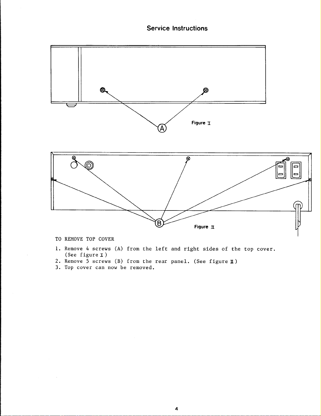
Service
Instructions
REMOVE
TO
1.Remove
(See
2.Remove
Top
3
.
figure
cover
TOP
4
S
COVER
screws
:[)
screws
can
now
(A)
(B)
be
from
from
removed
the
the
left
rear
.
and
right
panel.(See
sides
figure
of
the
II)
top
cover
.
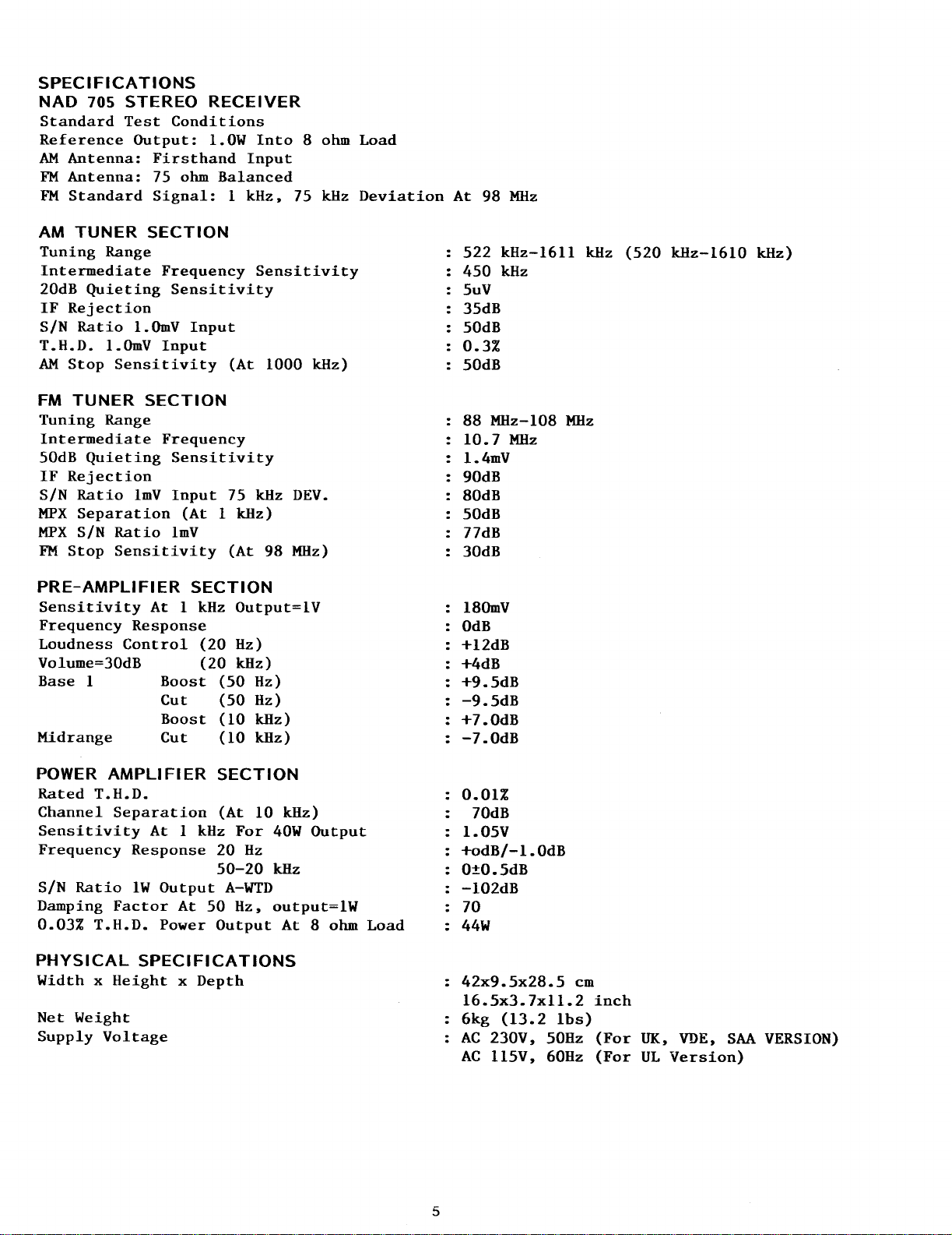
SPECIFICATIONS
NAD
Standard
Reference
AM Antenna
FM Antenna
FM
AM
Tuning
20dB
S/N
T
AM
FM
TuningRange
Intermediate
50dB
IF
S/N
MPX Separation
MPX
FM
705
Standard
TUNER
Range
Intermediate
Quieting
IF
Rejection
Ratio1.OmV
.H.D.1
Stop
.OmV
Sensitivity
TUNER
Quieting
Rejection
Ratio
S/N
Ratio
Stop
Sensitivity
STEREO
Test
Output:1
:
:
1mV
Conditions
Firsthand
75
ohm
Signal:1
SECTION
Frequency
Sensitivity
Input
Input
SECTION
Frequency
Sensitivity
Input
(At1kHz)
1mV
RECEIVER
.OW
Into
Input
Balanced
kHz,
Sensitivity
(At
75
kHz
(At
8
ohmLoad
75
kHz
1000 kHz)
DEV
.
98
MHz)
Deviation
At
98
522
450
5uV
.
35dB
50dB
0
.3Z
50dB
88
MHz-108MHz
10
.7
.1.4mV
90dB
80dB
50dB
77dB
30dB
MHz
kHz-1611
kHz
MHz
kHz
(520
kHz-1610
kHz)
PRE-AMPLIFIER
Sensitivity
Frequency
Loudness
Volume=30dB
Base
Midrange
POWER
RatedT
Channel
Sensitivity
Frequency
Ratio
S/N
Damping
0
.032
Control
1
AMPLIFIER
.H.D
Separation
Factor
T
.H.D
Response
Response
1W
PHYSICAL
Width
Net
Supply
x
Weight
Voltage
Height
SECTION
At
1
kHz
Output=lV
(20 Hz)
(20
kHz)
Boost
Cut
Boost
Cut
(50
(50
(10
(10
SECTION
.
(At
At
1
kHz For
20 Hz
50-20
Output
.
PowerOutputAt
At 50
A-WTD
Hz,
SPECIFICATIONS
x Depth
Hz)
Hz)
kHz)
kHz)
10 kHz)
40WOutput
kHz
output=lW
8
ohmLoad 44W
180mV
OdB
+12dB
+4dB
+9
.
-9.5dB
+7
.
-7.OdB
O
1
+odB/-1
0±0
.
-102dB
70
42x9
16
6kg
AC
AC
.5dB
.OdB
.O1Z
70dB
.05V
.5x3
.5dB
.5x28
(13
230V,
115V,
.OdB
.7xll
.2
.5
lbs)
50Hz
60Hz
cm
.2
inch
(For
UK,
(For UL
VDE,
Version)
SAA
VERSION)
AM
REAR
WARNING:TO
SHOCK,
TO
L
R
PRONO
RAIN
PR
G N
DO
NO
CO
PANEL
NOT
OR
MOISTURE
FM
750
ANTENNA
VIDEO
SOUND
CONNECTIONS
PREVENT
EXPOSE
.
G
I
TAPE
AUX
IN
FIRE
OR
THIS
1TAPE
OUT
IN
ELECTRIC
APPLIANCE
MULTI
2ROOMPREMAIN
OUT OUT
OEM
OEM
OUT
IN
OUT
L
.
R
0M
IN
SOFT
.
CLIPPING
NAD
ON
nlalaln
OFF
yyyy
A
N
+
B
MIMI
III
The
lightning
flash
with
triangle,isintendedtoalert
unnsulated
sure:that
maybeof
riskofelectric
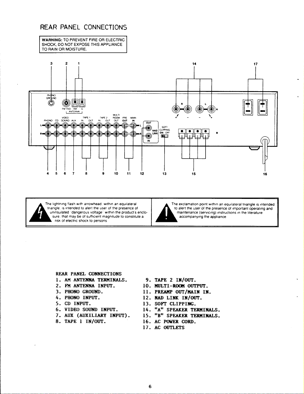
REAR
1.AM
2.FM
arrowhead
dangerousvoltage
shocktopersons
PANEL
ANTENNA
ANTENNA
3.PHONOGROUND
4.PHONOINPUT
5.CD
6.VIDEO
7
8
.
.
AUX
TAPE
INPUT
SOUND
(AUXILIARY
1
IN/OUT
within
.
the userofthe
sufficient
within
magnitudetoconstitute
CONNECTIONS
TERMINALS
INPUT
.
.
.
INPUT
.
10
an
equilateral
presence
the
.
.
INPUT)
products
.
.
12
of
enclo
a
9.TAPE
2
10.MULTI-ROOM
11.PREAMP
12.NAD
LINK
13.SOFTCLIPPING
14."A"
15."B"
SPEAKERTERMINALS
SPEAKERTERMINALS
16.AC POWERCORD
17.AC
OUTLETS
The
exclamation
to
alert
maintenance
accompanying
IN/OUT
OUT/MAIN
IN/OUT
the
userofthe
.
OUTPUT
.
.
point
withinanequilateral
presenceofimportant
(servicing)
Instructionsinthe
the appliance
.
IN
.
.
.
.
triangle
operating
literature
is
intended
16
and
FRONT
PANEL
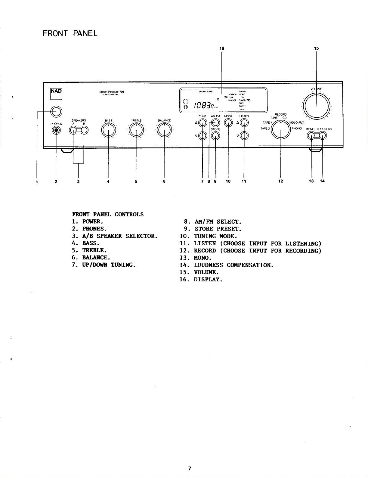
FRONT
1.POWER
2.PHONES
3
4.BASS
5.TREBLE
6.BALANCE
7.UP/DOWNTUNING
PANEL
A/B
.
CONTROLS
.
.
SPEAKERSELECTOR
.
.
.
8.AM/FM
STORE
9
.
.
.
10.TUNING
11
.
LISTEN
12
.
RECORD
13.MONO
14.LOUDNESSCOMPENSATION
15.VOLUME
16.DISPLAY
.
SELECT
PRESET
MODE
(CHOOSE
(CHOOSE
.
.
.
.
.
INPUT
INPUT
FOR
FOR
.
LISTENING)
RECORDING)
REMOTE
CONTROL
TRANSMITTER
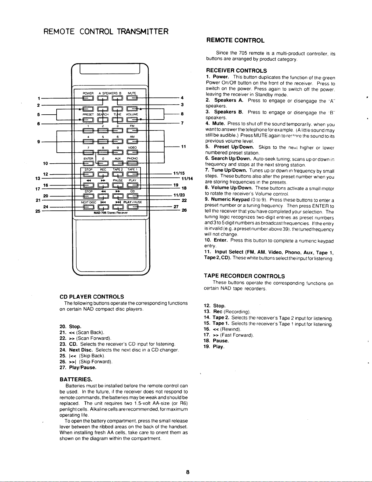
REMOTECONTROL
Since
the
705
buttons
are
remoteisa
arranged
by
product
multi-product
category
.
controller,
its
RECEIVER
1.Power
Power
switchonthe
leaving
2.Speakers
speakers
3
.
SpeakersB.
speakers
4
.
Mute.Presstoshut
wanttoanswer
stillbeaudible.)Press
previous
5.Preset
numbered
6.Search
frequency
7.Tune
steps.These
are
storing
8.Volume
to
rotate the
9.Numeric
preset
tell
the
tuning
and
3to5
is
invalid
will
not
10.Enter
entry
.
11.Input
Tape2,CD).These
CONTROLS
.This
button
On/Off
buttononthe
power
the
receiverinStandby
A
.
.
.
the
volume
level
Up/Down
preset
Up/Down
and
stopsatthe
Up/Down
buttons
frequenciesinthe
Up/Down
receiver's
Keypad
numberora
receiver
logic
digit
(e .g.a
change
.
Select
that
recognizes
numbers
preset
.
Press
duplicates
front
.
Press
againtoswitch
Presstoengage
Presstoengage
telephone
MUTE
.
.
station
.
Auto-seek
.
Tunesupor
also
.
These
Volume
(0 to 9).Press these
tuning
you have
as
number
this
buttontocomplete
(FM,
white
mode
off
the
sound
for
example.(A
againtorec'nre
Skipstothe
.
next
strong
alter
the
presets
buttons
control
frequency
completed
two-digit
broadcast
above
AM,
Video,
buttons
select
the
function
of
the
receiver.Press
off
.
or
disengage
or
disengage
temporarily.when
little
the
ne~[
higher
tuning;scans
down
preset
.
activateasmall
Then
entriesaspreset
frequencies.If
39).the
Phono,
up
station
.
in
frequencybysmall
number
.
buttonstoenter
press
your
selection.The
tuned
a
numeric
Aux,
the
input
for
of
the
green
the
power
the
the
you
sound
may
soundtoits
or
lower
or
down
when
you
motor
ENTER
numbers
the
entry
frequency
keypad
Tape
listening
to
.
A"
B
in
a
to
1,
CD
PLAYER
The
following
on
certain
NAD
20.Stop
21.<<
22.>>
23.CD.Selects
24.Next
25.1«
26.>>I
27.Play/Pause
BATTERIES
be
remote
replaced.The
penlight
operating
lever
When
shown
(Scan
(Scan
(Skip
(Skip
Batteries
used.In
commands,
cells
To
open
between
installing
on
.
Back)
Forward)
Disc.Selects
Back)
Forward)
.
must be
the
Alkaline
.
life
.
the
battery
the
diagram
the
CONTROLS
buttons
operate
compact
.
future,ifthe
unit
freshAAcells,
disc
.
.
the
receiver'sCDinput
the
next
.
.
installed
the
batteries
requires
cells
are
compartment,
ribbed
areas on
within
the
corresponding
players
.
for
discinaCDchanger
before the
receiver
two1.5-volt
recommended,
take
the
remote
does
maybeweak
press
the
backofthe
caretoorient
compartment
AA-size
the
functions
listening
control
not
respond
and
should
(or
for
maximum
small
release
handset
them
.
TAPE
RECORDERCONTROLS
These
buttons
operate
the
certain
NAD
tape
recorders
12.Stop
13.Rec
14
15.Tape1.
16
17.>>
.
.
can
to
be
R6)
as
18.Pause
19
.
.
(Recording)
.
Tape2.
.<<(Rewind)
.
Play
(Fast
.
Selects
Selects
Forward)
.
.
the
the
.
.
corresponding
.
receiver's
receiver's
Tape2input
Tape1input
functions
for
listening
for
listening
on
.
.
TC404
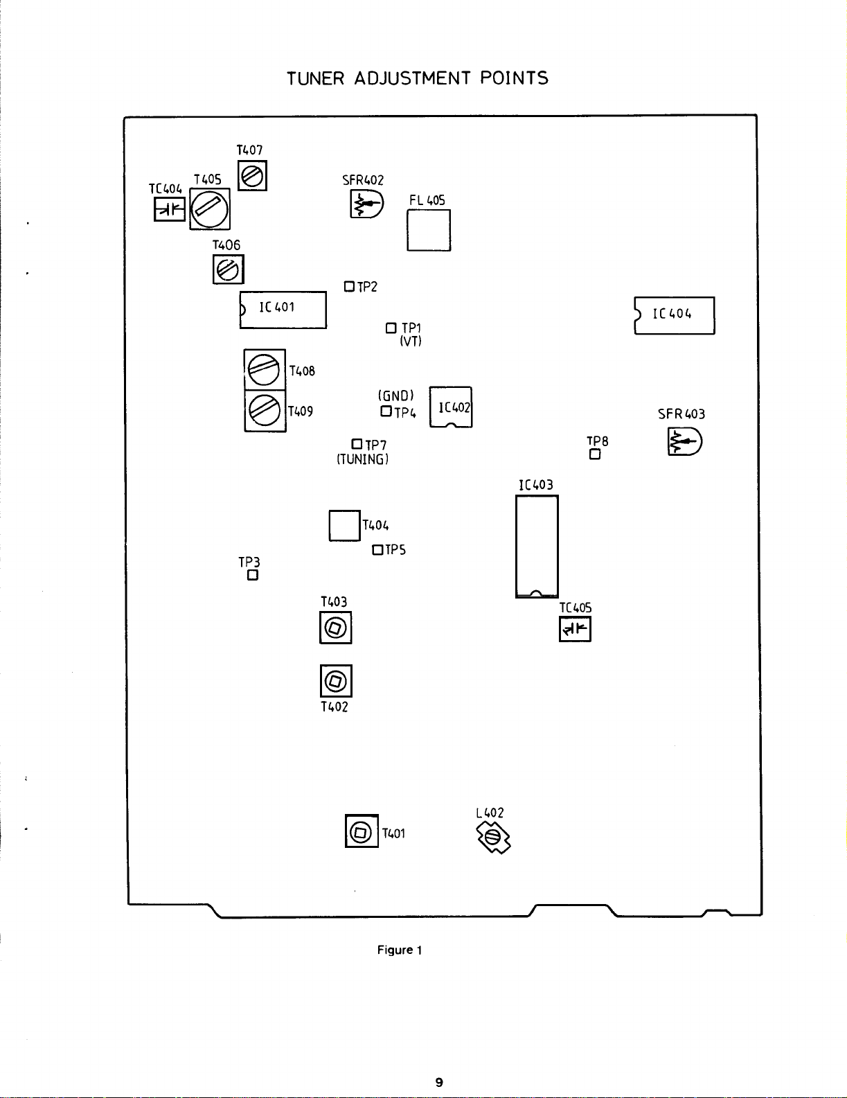
TUNER
T407
T
Fo-1
T406
me
T408
T409
ADJUSTMENT
SFR402
p
TP2
O
O
(GNO)
OTP4
077
(TUNING)
FL
D
TP1
(VT)
40S
POINTS
TP8
O
SF
R403
E)
TP3
IC403
T404
0
OTP5
O
T403
TC405
10
Wl
T402
L402
T401
O
Figure
1
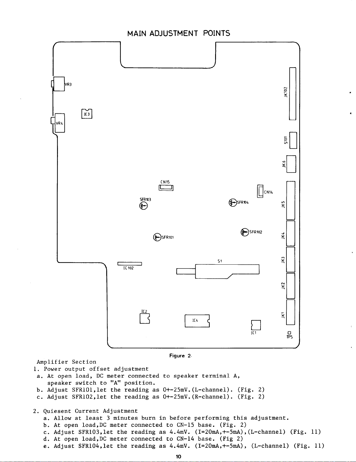
MAIN
ADJUSTMENT
POINTS
Amplifier
1.Poweroutputoffset adjustment
a.At
speaker
b.AdjustSFR101,let
c.Adjust SFR102,let
2.QuiesentCurrent
a.Allow
b
.
At
c
.
AdjustSFR103,let
d
.
At
e
.
AdjustSFR104,let
open
open
open
Section
load,
switch
at
least
load,DC
load,DC
DC
meter
to
"A"
the
the
Adjustment
3
minutes
meter
meter
position
reading
reading
the
the
connected
connected
reading
connected
reading
burn
Figure2.
to
speaker
.
as
0+-25mV
as
0+-25mV
in
before
to
CN-15
as4.4mV.(I=20mA,+-5mA),(L-channel)
to
CN-14
as4.4mV.(I=20mA,+-5mA),
terminal
.(L-channel)
.(R-channel)
performing
base.(Fig.2)
base.(Fig
A,
.
(Fig
(Fig.2)
.
this
2)
.
adjustment
(L-channel)
2)
.
(Fig.11)
(Fig.11)
SPEAKER
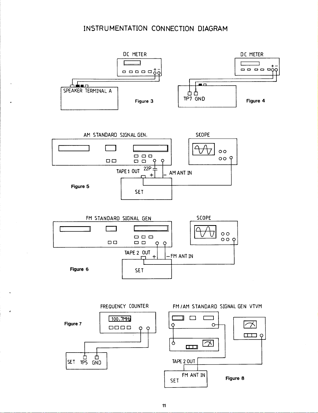
INSTRUMENTATION
DC
TERMINAL
AM
STANDARD
0
A
SIGNAL
0
TAPE1OUT2
METER
Figure
GEN
0
00
CONNECTIONDIAGRAM
3
00
.
P
+T
AM
ANT
SCOPE
D
IN
00
00
OC
METER
4
D
Figure
Figure
Figure
5
SET
FM
STANDARD
6
FREQUENCY
00
100.7M
SIGNAL
00o
0
TAPE2OUT
n
SET
COUNTER
GEN
0
SCOPE
n
0
0
-FM
ANT
FM
/AM
IN
STANDARD
+
00
00
SIGNAL
GEN
VTVM
7
0000
TAPE 2
SET
FM
OUT
ANT
IN
Figure
8
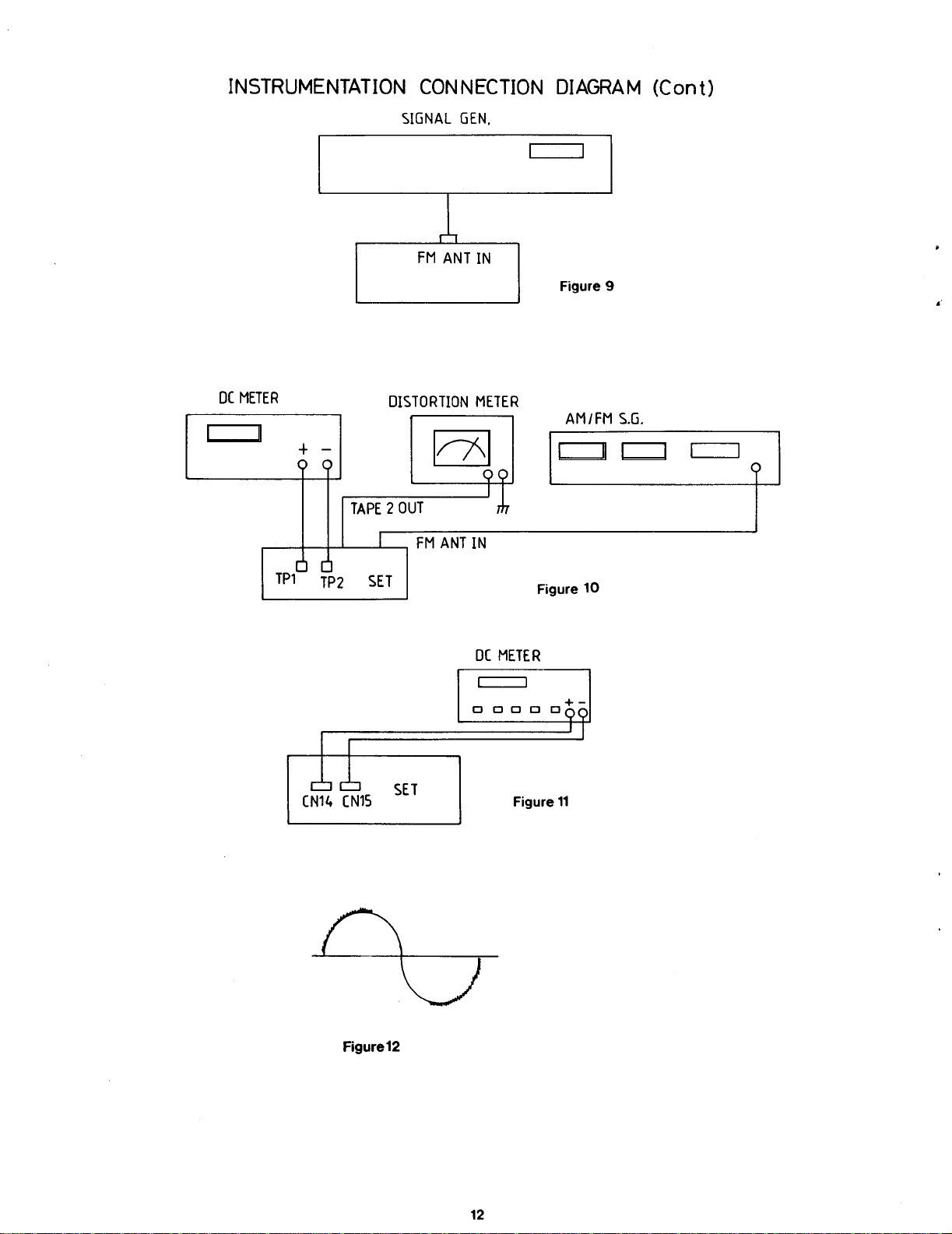
INSTRUMENTATION
CONNECTION
DIAGRAM
(Cont)
DC
METER
TP1
O
oa
O
TP2
SIGNAL
DISTORTION
TAPE2OUT
SET
FM
GEN
D
ANT
.
METER
IN
AM/FM
Figure
10
S
.G
.
Figure
12
SET
DC
METER
Figure
11
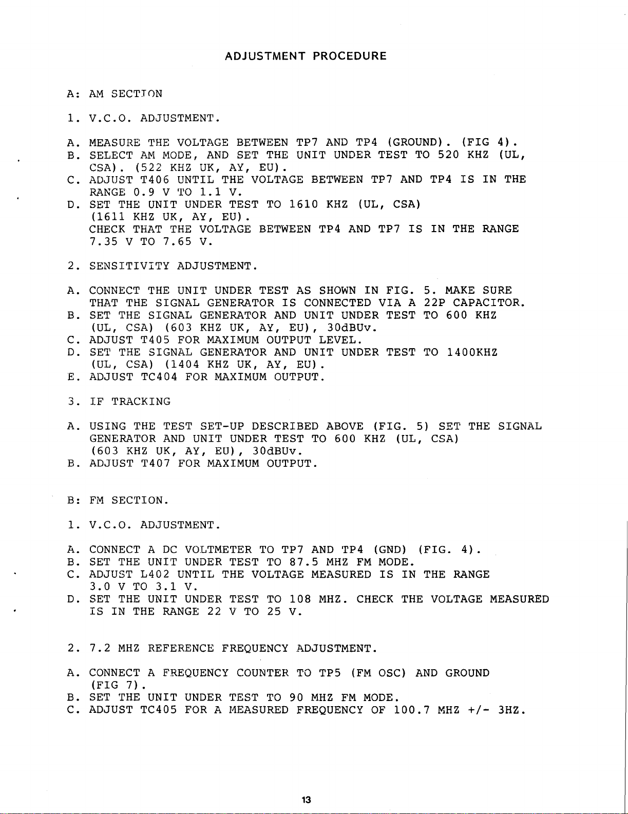
A:AM SECTION
ADJUSTMENT
PROCEDURE
1.V
.C .O
MEASURE
A
.
B.SELECT
CSA)
C.ADJUST
RANGE
ADJUSTMENT
.
AM
.
(522
T406
0
.9
D.SET THE
(1611
KHZ
CHECKTHAT THE
7
.35
V
TO7.65V.
2.SENSITIVITY
A.CONNECT
THAT
THE
B.SET THE
(UL,
C.ADJUST
D.SET
(UL,
E.ADJUST
3.IF
CSA)
T405
THE
CSA)
TC404
TRACKING
THE
VOLTAGEBETWEEN
MODE,
KHZ
AND
UK,
UNTIL
1
TO
UNDER
AY,
.1
V
UNIT
UK,
VOLTAGE
ADJUSTMENT
THE
UNIT
SIGNAL
SIGNAL
(603
SIGNAL
(1404
GENERATOR
KHZ
FOR
GENERATOR
GENERATOR
MAXIMUM
KHZ
FOR
.
SET
AY,
THE
V
.
TEST
EU)
.
UNDER
UK,
UK,
MAXIMUM
TP7
AND
THE
UNITUNDER
EU)
.
VOLTAGEBETWEEN
1610
TO
BETWEEN
KHZ
TP4
.
TEST AS SHOWN
IS
CONNECTED
AND
AY,
OUTPUT
AND
AY,
OUTPUT
UNIT
EU),
UNIT
EU)
UNDER
30dBUv
LEVEL
UNDER
.
.
TP4
(UL,
AND
.
(GROUND)
TEST TO
TP7
AND
CSA)
TP7
IS
IN
FIG.5.MAKE
VIA
A
TEST
.
TEST
520
TP4
IN
22P
TO
TO
.
(FIG
KHZ
IS IN
THE
RANGE
SURE
CAPACITOR
600
KHZ
1400KHZ
4)
(UL,
THE
.
.
A.USING
GENERATOR
SECTION
.C
.O
KHZ
.
(603
B
.
ADJUST
B:FM
1.V
A.CONNECT
B.SET THE
ADJUST
C
.
3 .0
V TO3.1V.
D.SET THE
IS
IN
2.7 .2
MHZ
A.CONNECT
(FIG
7)
B.SET THE
C.ADJUST
THE
TEST
AND
UK,
T407
FOR
.
ADJUSTMENT
A
DC
UNIT
L402
UNTILTHE
UNIT
THE
RANGE
REFERENCE
A
FREQUENCY
.
UNIT
TC405
SET-UP
UNIT
AY,
UNDER
EU),
MAXIMUM
.
VOLTMETER
UNDER
UNDER
22
TEST
TEST
V
FREQUENCY
UNDER
FOR A
TEST TO
MEASUREDFREQUENCY
DESCRIBED
30dBUv
OUTPUT
TO
TO
VOLTAGE
TO
TO
25V.
COUNTER
TEST TO
.
.
AND
TP7
87
.5
MEASURED
108
ADJUSTMENT
TO
MHZ
90
ABOVE
600
TP4
MHZ
FM
(FIG
KHZ
(GND)
MODE
MHZ.CHECK
.
TP5
FM
(FM
MODE
OF
IS
OSC)
100
.
(UL,
IN
THE
.
5)
(FIG
.
AND
.7
THE
SET
CSA)
4)
.
THE RANGE
VOLTAGE
GROUND
+/-
MHZ
SIGNAL
.
MEASURED
3HZ
.
ADJUSTMENT
PROCEDURE
(Cant
.)
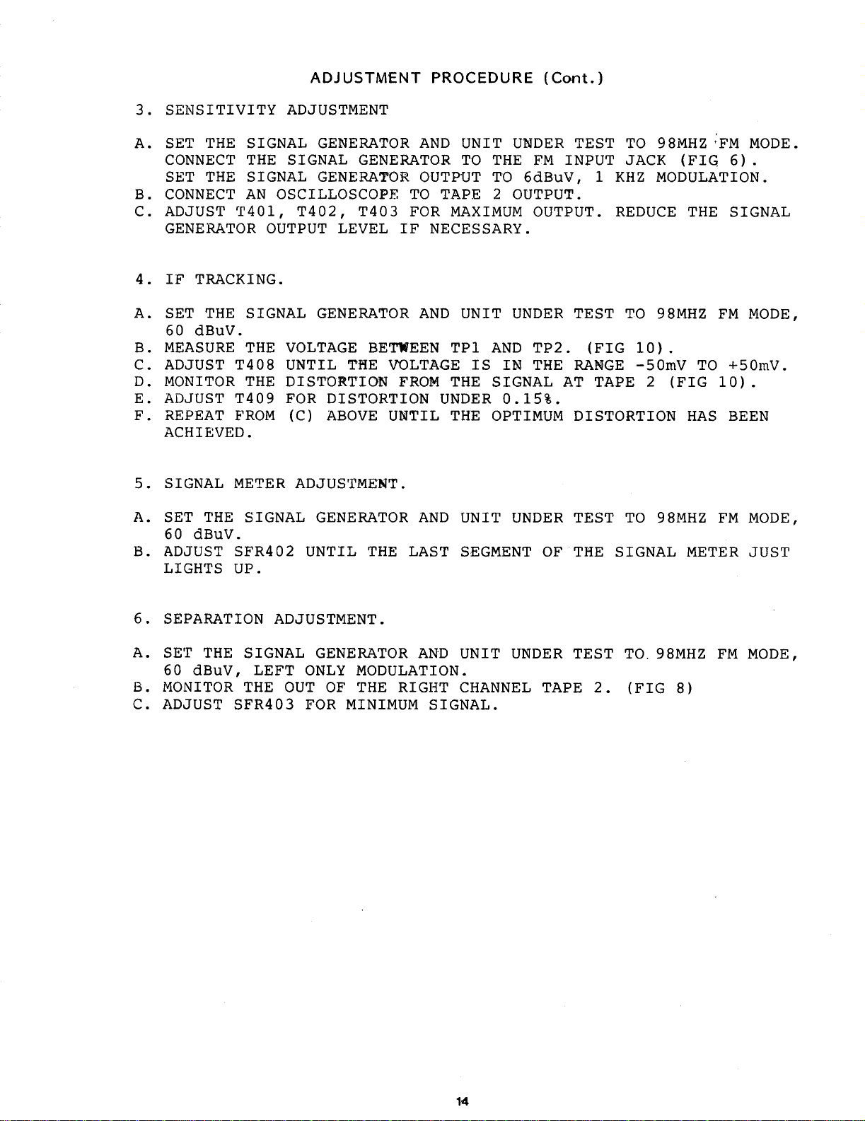
3.SENSITIVITY
A.SET THE
CONNECT
SET THE
B.CONNECT
C.ADJUST
GENERATOR
4.IF
TRACKING
A.SET
60
dBuV
B.MEASURE
C.ADJUST
D.MONITOR
E.ADJUST
THE
SIGNAL
THE
SIGNAL
AN
7401,
OUTPUTLEVEL
SIGNAL
.
THE
T408
THE
T409
F.REPEATFROM
ACHIEVED
5.SIGNAL
A.SET THE
60
dBuV
.
METERADJUSTMENT
SIGNAL
.
B.ADJUST SFR402
LIGHTS
UP
.
ADJUSTMENT
GENERATOR
SIGNAL
GENERATOR
GENERATOR
OSCILLOSCOPE
T402,
T403
.
GENERATOR
VOLTAGEBETWEEN
UNTIL
THE
VOLTAGE
DISTORTION
FOR
DISTORTIONUNDER
(C)
ABOVE
UNTILTHE
GENERATOR
UNTIL
THE
AND UNIT
TO
OUTPUT
TO TAPE
FOR
MAXIMUM
IF
NECESSARY
AND UNIT
TP1
FROM THE
.
AND
UNIT
LAST
SEGMENT
UNDER
THE
FM INPUTJACK
TO
6dBuV,
2
OUTPUT
OUTPUT
.
UNDER
AND
TP2
.
IS IN
THE
SIGNALAT TAPE
0
.15%
.
OPTIMUM
UNDER
TEST
OF THE SIGNAL
TEST TO
98MHZFM
(FIG.6)
1
KHZ
MODULATION
.
.
REDUCETHE SIGNAL
TEST
RANGE
(FIG
TO
98MHZ FM
10)
-50mV
2
.
(FIG
DISTORTION
TO
98MHZ
METER
TO
HAS
+50mV
10)
BEEN
FM
MODE
.
.
MODE,
.
MODE,
JUST
.
.
6.SEPARATION
A.SET
60
THE
dBuV,
B.MONITOR
C.ADJUST
ADJUSTMENT
SIGNAL
LEFT ONLY
THE
OUT OF THE RIGHT
SFR403
GENERATOR
MODULATION
FOR
MINIMUM
.
AND UNIT
.
CHANNEL
SIGNAL
.
UNDER
TAPE
TEST TO
2
.
(FIG
.98MHZ
8)
FM MODE,
 Loading...