

MV Agusta Rivale 800, Rivale 800cc User Manual

User’s manual
English Version

- 2 -
Dear Customer,
We wish to thank you for your preference and congratulate you on purchasing your new Rivale 800.
Your choice is a reward for the passionate effort our technicians have put into giving the Rivale 800 functional and aesthetic characteristics that place it above the finest motorcycles currently available on the
market, making it an exclusive and sought-after item.
If, from a purely technical standpoint, the Rivale 800 represents an internationally recognized point of
reference on account of the innumerable innovations it introduces, its sleek, timeless design wonderfully combines a glorious past with the new millennium.
The combination of these elements, which was made possible by love of detail, passion, and the desire
to realize a technically and aesthetically superior motorcycle, allows the Rivale 800 to soar above passing fashions, giving it the privilege of being considered a unique item.
For further information, please feel free to contact the MV Agusta Customer Care Service.
Have a good time!
MV Agusta
Giovanni Castiglioni
Chairman
- 3 -
CONTENTS
chap. Subjects covered page
1 GENERAL INFORMATION 5
1.1. Purpose of the manual 5
1.2. Symbols 6
1.3. Contents of the digital support 7
1.4. Identification data 8
2 SAFETY INFORMATION 11
2.1. Allowed use of the vehicle 11
2.2. Maintenance 11
2.3. Accessories and modifications 12
2.4. Vehicle load 12
3 CONTROLS AND INSTRUMENTS 14
3.1. Location of controls and instruments 14
3.2. Sidestand 15
3.3. Handlebar controls, left side 16
3.4. Handlebar controls, right side 18
3.5. Ignition switch and steering lock 21
3.6. Gear lever 24
3.7. Instruments and warning lights 25
3.7.1. Warning lights 26
3.7.2. Multifunction display 27
3.8. Table of lubricants and fluids 28
chap. Subjects covered page
4 OPERATION 29
4.1. Using the motorcycle 29
4.2. Running-in 30
4.3. Starting the engine 32
4.4. Selecting and setting the display functions 35
4.4.1. Selecting the display functions 36
4.4.2. Trip reset 41
4.4.3. “SPEED LIMITER” Mode 43
4.4.4. “TC” Mode 45
4.4.5. Chronometer 46
4.4.6. ABS Mode 55
4.4.7. “QUICK SHIFT” Mode 57
4.4.8. Clock settings 58
4.4.9. How to select the mapping
of the control unit 60
4.4.10. Warning/malfunction alerts 72
4.5. Refuelling 75
4.6. Glove compartment 77
4.7. Parking the motorcycle 78
5 ADJUSTMENTS 80
5.1. List of adjustments 80
CONTENTS
chap. Subjects covered page
5.2. Table of adjustments 82
5.3. Adjusting the front brake lever 83
5.4. Adjusting the rearview mirrors 83
5.5. Adjusting the front suspension 84
5.5.1. Spring preload (front suspension) 84
5.5.2. Rebound damper (front suspension) 85
5.5.3. Compression damper (front suspension) 85
5.6. Adjusting the rear suspension 86
5.6.1. Rebound damper (rear suspension) 87
5.6.2. Compression damper (rear suspension) 88
5.7. Headlight adjustment 89
- 4 -
- 5 -
GENERAL INFORMATION 1
1
1.1. Purpose of the manual
This User’s Manual contains the necessary information for a
correct and safe use of the motorcycle.
The User’s Manual is also supplied in electronic format (.pdf)
on the digital support supplied and it can be printed or viewed
on any PC, equipped either with Windows or Mac operative
system.
We recommend to carefully read the User’s Manual before
using your motorcycle, and to make sure that anyone who
uses the motorcycle had previously made the same.
GB
Copyright
MV AGUSTA Motor Spa
All rights reserved
- 6 -
GENERAL INFORMATION 1
1
GB
1.2. Symbols
Sections of text that are particularly important in terms of personal safety or possible damage to the
motorcycle are marked with the following symbols:
Danger - Failure to observe these prescriptions, even in part, may pose a serious hazard
to the driver’s and other people’s safety.
Caution - Failure to observe these prescriptions, even in part, may result in damage to the
motorcycle.
The following symbols give an indication of who is supposed to perform the different adjustments and/or
maintenance operations:
Information on operations that can be carried out by the user.
Information on operations that
must be carried out only by authorized personnel.
The following symbols are used to provide further information:
The symbol points out the requirement to use a tool or a special equipment in order
to correctly perform the described operation.
§ The “ § ” symbol refers the reader to the chapter identified by the number that follows.
- 7 -
GENERAL INFORMATION 1
1
GB
1.3. Contents of the digital support
Inside the digital support supplied you will find, besides the
User’s Manual, the Maintenance Manual, the World Dealer
Guide and the Warranty Booklet.
When delivering the bike, your Dealer has also supplied the
Warranty and Pre-Delivery Certificate.
We recommend to keep it together with the motorcycle documents and with the service coupons that are given at the
moment of servicing the bike.
IMPORTANT
The copies of the Warranty and Pre-Delivery Certificate must
be filled in by the Dealer. A copy of the certificate must be
given to the Customer, a second copy must be kept by the
Dealer and the third one must be sent to the importer.
The dealer must always fill in the recommended maintenance
service coupons. They must be kept by both, the Customer
and the Dealer.

- 8 -
GENERAL INFORMATION 1
1
GB
1.4. Identification data
1) vehicle identification number
2) engine serial number
3) homologation data
Motorcycle identification
The motorcycle is identified by the vehicle identification number. When placing orders for spare
parts, in addition to this number, you may be
required to provide the engine serial number, the
colour code and the key identification.
We recommend writing down the main numbers in
the spaces provided below.
FRAME No.:
ENGINE No.:
2) engine serial number
1) vehicle identification number
3) homologation data
GENERAL INFORMATION 1
1
GB
- 9 -
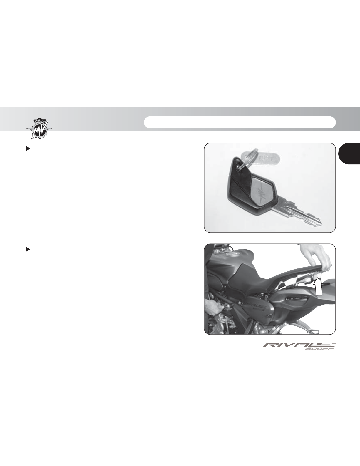
Identification of motorcycle colour combination
The colour code must be mentioned when ordering
body spares. It can be read on the lower right side of the
fuel tank.
In order to get to the colour code label, it is necessary
to remove the saddle, unblocking it with the key, by lifting it from the back and sliding it from the pivot on the
tank.
Motorcycle key identification
A key is supplied in duplicate for both the ignition and all
the locks. Keep the duplicate in a safe place.
When placing orders for spare keys, you may be
required to provide the key identification number. It is
advised to note this number in the following space:
KEY Nr.:
- 10 -
GENERAL INFORMATION 1
1
GB
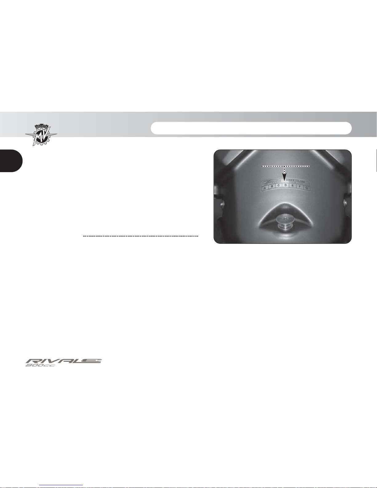
After removing the seat, it is possible to get to the colour
code label. On this label you can read the motorcycle
colour combination, which determines the painting of
the bodywork parts.
We recommend writing down the colour code in the
space provided below:
COLOUR CODE:
Colour code label
- 11 -
SAFETY INFORMATION 2
2
GB
2.1. ALLOWED USE OF THE VEHICLE
Your motorcycle has been strictly designed for
use on road or highway route.
WARNING
Occasionally, it is possible to use your
motorcycle on race track during noncompetitive events.
In this case, however, in consequence of
the higher stresses affecting the bike
during this specific use, we recommend
to have its conditions checked by an
authorized MV Agusta Service Center
before and after using it.
Any other use of the vehicle is prohibited and explicitly excluded.
You can find further information about the use of
the vehicle in the section no. 4 of this Manual.
2.2. MAINTENANCE
In order to guarantee the maximum efficiency and
reliability of the vehicle, it is necessary to perform
the programmed maintenance operations reported in the Maintenance Manual.
MV Agusta recommends that all maintenance
operations are performed only by skilled personnel from an authorized MV Agusta Service
Center.
Anyway, if you decide to have the maintenance
operations performed by non-authorized workshops, you must ensure that they have the skills
and the specific tools necessary to perform the
above operations.
WARNING
The MV Agusta Warranty could not be
valid if non-authorized workshops had
performed operations on the bike in a
different way from what is described on
the Technical Circular Letters and on the
related MV Agusta Workshop Manuals.
- 12 -
SAFETY INFORMATION 2
2
GB
2.3. ACCESSORIES AND MODIFICATIONS
WARNING
MV Agusta prohibits to make any modification to its motorcycles.
This is necessary to preserve the safety
of its Customers.
Anyway, it is possible to customize your motorcycle by consulting the extensive MV Agusta
Accessory Catalogue.
WARNING
The installation of some of the above
accessories could invalidate the bike
homologation, and consequently make
the bike not furtherly usable on public
roads.
If you have doubts, we suggest to refer to your MV
Agusta Dealer in order to choose the accessories
which can better suit your needs.
2.4. VEHICLE LOAD
Your motorcycle is designed for use by the rider
and it can also seat a passenger.
To use the vehicle in complete safety and in
accordance with the Highway Code provisions, it
is compulsory that the following maximum load
conditions are never exceeded:
RIVALE 800
Maximum technically admissible mass:
362 kg
Maximum transportable mass:
170 kg
The maximum technically admissible mass represents the sum of the following masses:
• mass of the motorcycle in running order;
• mass of the pilot;
• mass of the passenger;
• mass of the luggage and of the accessories.

- 13 -
SAFETY INFORMATION 2
2
GB
WARNING
Since the load can strongly affect handling, braking, performance and safety
characteristics of your motorcycle, you
should always keep in mind the following warnings.
• NEVER OVERLOAD YOUR MOTORCYCLE! Driving an overloaded motorcycle can cause damage to the tyres, loss
of control of the vehicle and serious
injury. Verify that the total weight
(including the weight of the motorcycle,
the driver, the passenger, the load and
all the accessories) does not exceed the
maximum load value specified for your
vehicle.
- 14 -
CONTROLS AND INSTRUMENTS 3
3
GB
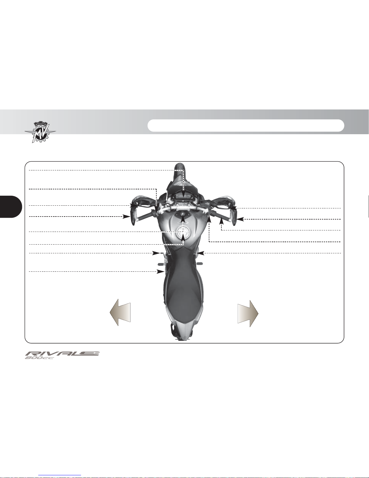
3.1. Location of controls and instruments
Instruments and warning lights (§3.7.)
Rearview mirror (§5.1.)
Clutch lever (§5.1.)
Left handlebar electrical controls (§3.3.)
Fuel tank cap (§4.5.)
Gear lever (§3.6. and §5.1.)
Sidestand (§3.2.)
Ignition switch and steering lock
(§3.5.)
Rearview mirror (§5.1.)
Front brake lever (§5.1.)
Throttle twist grip (§3.4.)
Rear brake lever (§5.1.)
Right handlebar electrical controls (§3.4.)
Left side
Right side
- 15 -
CONTROLS AND INSTRUMENTS 3
3
GB
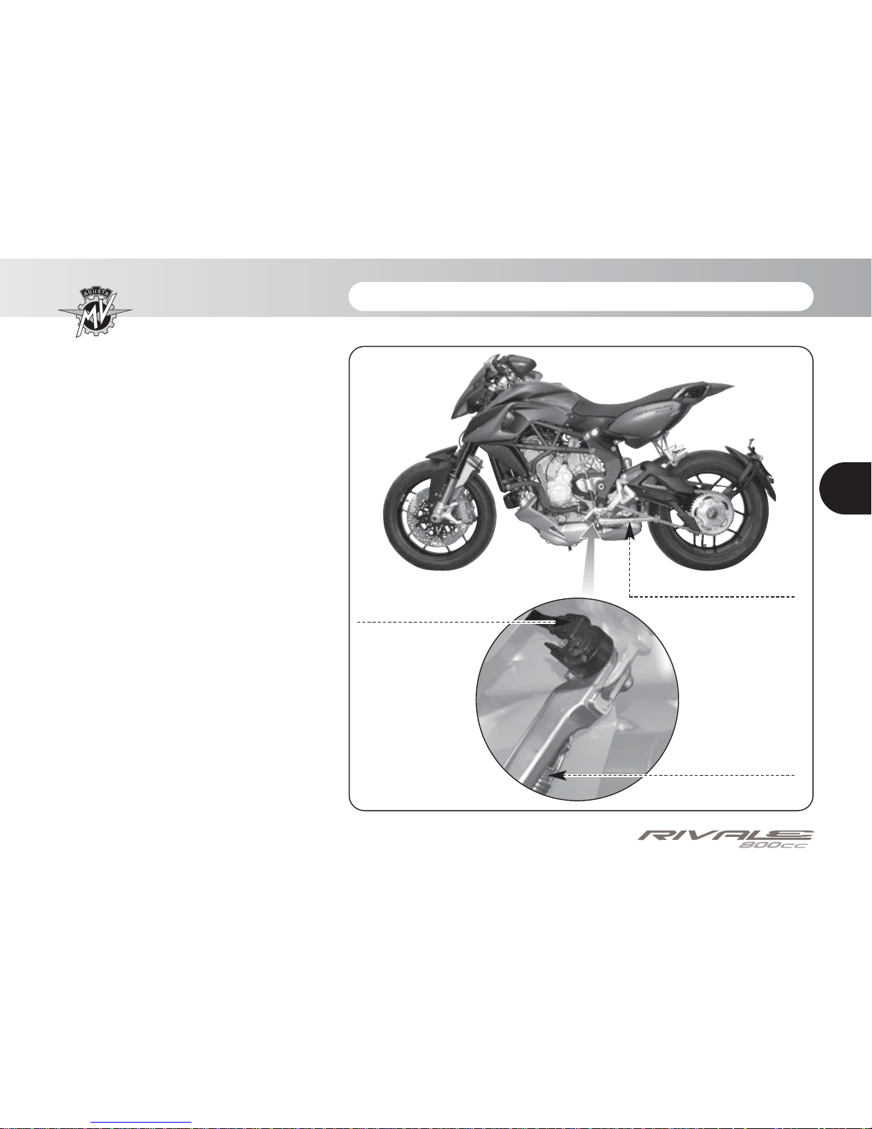
3.2. Sidestand
The sidestand is equipped with a
safety switch that prevents the
motorcycle from moving off while
the stand is down.
If the rider attempts to engage the
gears while the engine is running
and the stand is down, the switch
automatically turns off the engine
by cutting the current supply.
If the motorcycle is parked (sidestand down) and the gears are
engaged, the switch prevents the
engine from being started, thereby
avoiding the risk of accidentally toppling the vehicle.
Sidestand
Dual return
spring
Safety switch
- 16 -
CONTROLS AND INSTRUMENTS 3
3
GB
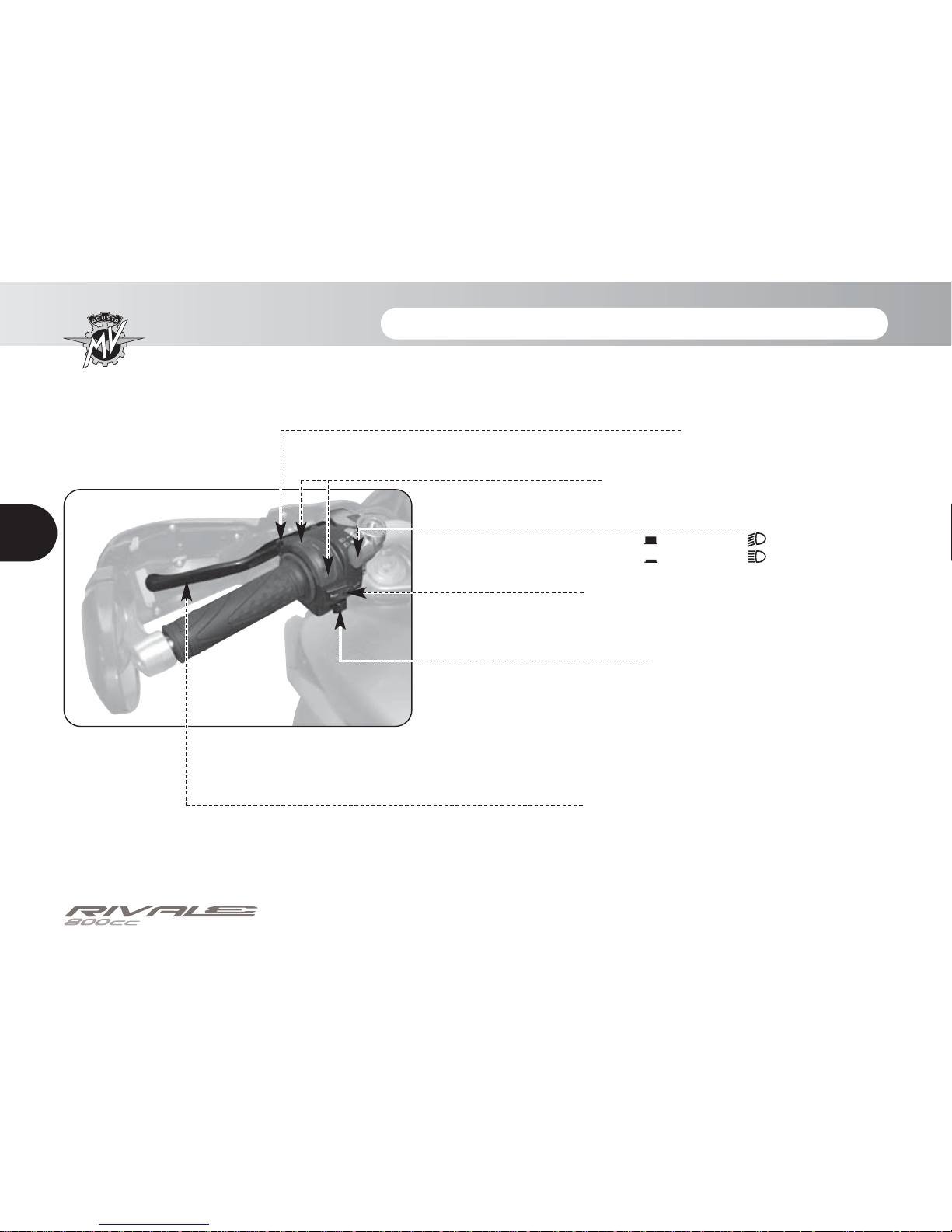
3.3. Handlebar controls, left side
High beam flasher button
Press the button repeatedly.
Low/high beam button
Button not pressed in : low beam
Button pressed in : high beam
Turn indicator switch
Shifting the lever to the left or right switches on the left or
right turn indicators. The switch then returns to the central
position. Press to turn off the indicators.
Horn button
Press to operate the warning horn.
Clutch lever
Move towards/away from the handgrip to release/engage
the clutch.
SET/OK button
Press to change the dashboard functions (§ 4.4).
CONTROLS AND INSTRUMENTS 3
3
GB
High beam flasher button
It is used to attract the attention of other road users in case of danger. When the high beam is on, the function
is inactive.
SET/OK button
The SET button enables to select the display digits to carry out adjustments, while the OK button enables to
confirm the set digits.
Low/high beam button
Under normal conditions, the low beam is on. The high beam can be switched on by pressing the button when
allowed by the traffic and road conditions.
Horn button
It is used to attract the attention of other road users in case of danger.
Turn indicator switch
It is used to show the rider’s intention to change direction or lane.
WARNING
Failure to switch the turn indicators on or off at the right time may cause an accident in that the
other road users may draw incorrect conclusions about the direction of motion of the vehicle.
Always switch on the indicators before turning or changing lanes. Then be sure to switch off the
indicators after completing the operation.
Clutch lever
It engages/disengages the clutch.
- 17 -
- 18 -
CONTROLS AND INSTRUMENTS 3
3
GB
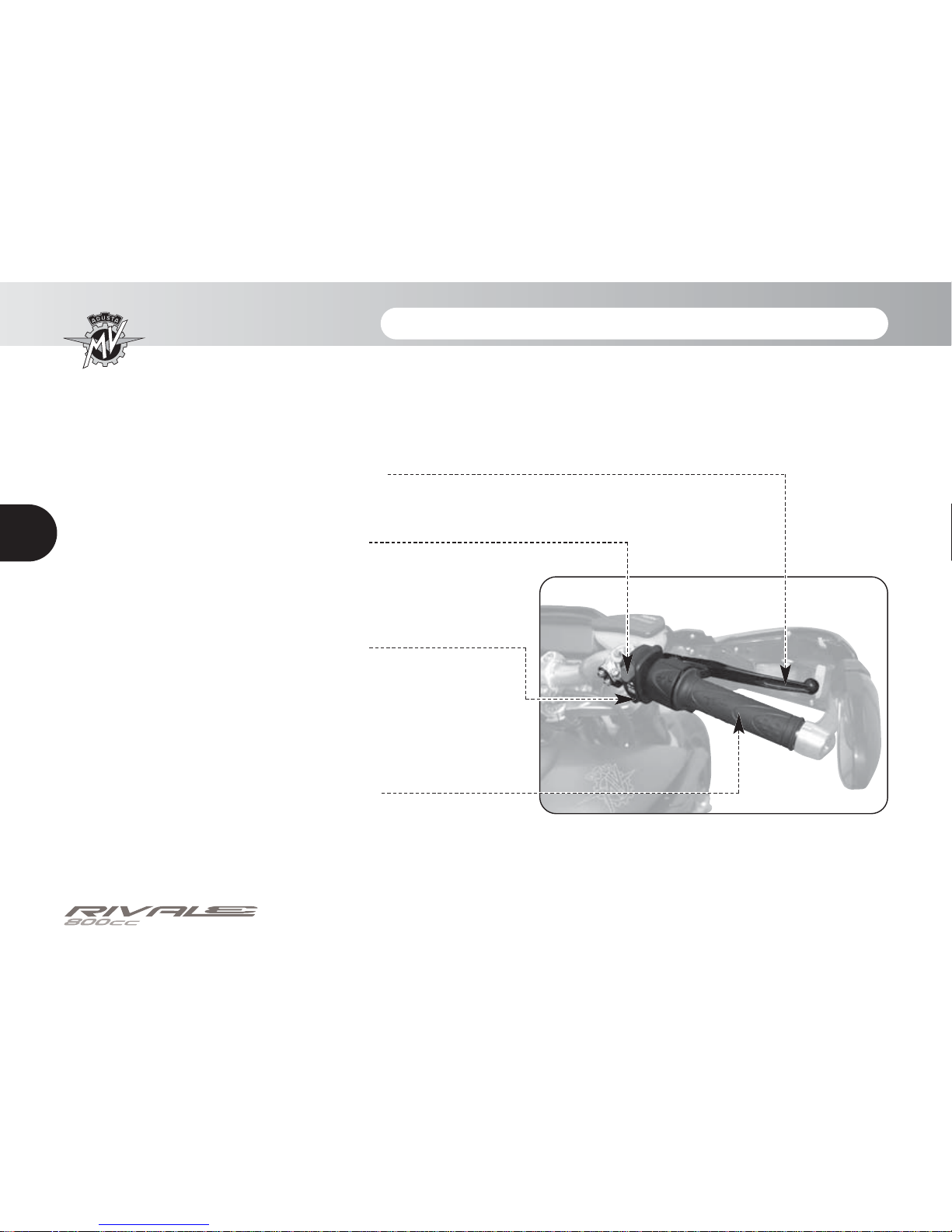
3.4. Handlebar controls, right side
Engine stop switch
Stops the engine and prevents it from being restarted.
Engine start button
Starts the engine. To be released as soon as the engine starts.
When the engine is running, pressing the button selects the dis-
play functions.
Throttle twist grip
Rotate counterclockwise to increase engine speed.
Front brake lever
Pull to the lever to apply the front brake.
- 19 -
CONTROLS AND INSTRUMENTS 3
3
GB
Engine stop switch
It is used to switch off the engine in an emergency. The ignition circuit is disabled, preventing the engine
from being restarted. To be able to restart the engine, return the switch to its original position.
NOTE: Under normal conditions, do not use this switch to shut off the engine.
Engine start button
It is used to start the engine and, when the engine is running, to select the different functions of the display installed on the instrument panel.
CAUTION
To avoid damaging the electrical equipment, be sure not to hold down the button for longer
than 5 consecutive seconds.
If, after some attempts, the engine does not start, refer to the chapter “TROUBLESHOOTING” later in this manual.
Throttle twist grip
It controls the fuel-air mixture supplied to the engine, which regulates engine speed. To increase engine
speed, rotate the hand grip from its idle position counterclockwise.
WARNING
If your motorcycle has toppled over or has been involved in an accident, have the working
of the throttle control checked by a MV Agusta authorized center before restarting.
- 20 -
CONTROLS AND INSTRUMENTS 3
3
GB
Front brake lever
It controls a hydraulic circuit that operates the front wheel braking system.
Antilock Braking System (ABS) *
Some Rivale models are equipped with a power-assisted braking system (ABS - Antilock Braking
System), which prevents the wheels from locking up during emergency brakings, thus guaranteeing the
stability of the vehicle and shortening braking distances.
WARNING
When the ABS system is activated, vibrations could be perceptible through the brake lever
or brake pedal. When this event occurs, it is recommended to keep pressed the braking
control devices in order to allow the vehicle to complete the braking.
WARNING
If the ABS system has a fault or is deactivated, the related warning light on the dashboard
turns on (see § 3.7.1.). From this moment on, the antilock braking system could not be available when braking. If there is a fault in the ABS system, it is recommended to resume riding at reduced speed and contact a MV Agusta authorized service centre. If the ABS system is turned off, follow the activation procedure described at § 4.4.6.
(*):
This function is present only on certain models
- 21 -
CONTROLS AND INSTRUMENTS 3
3
GB
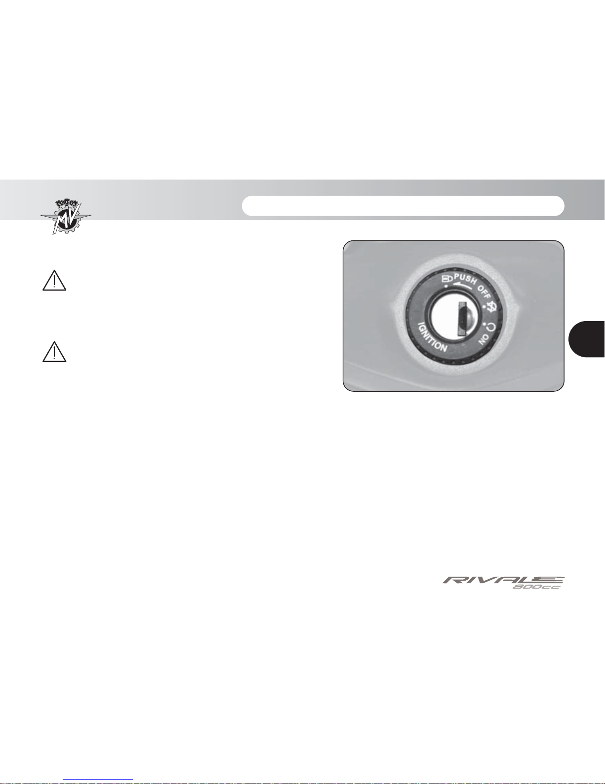
3.5. Ignition switch and steering lock
WARNING
Do not attach a ring or any other object to the
ignition key as they may hinder the steering
action.
WARNING
Never attempt to change the switch functions
while riding, as you may lose control of the
vehicle.
The ignition switch enables and disables the electrical
circuit and the steering lock. The three positions of the
switch are described below.
- 22 -
CONTROLS AND INSTRUMENTS 3
3
GB
OFF position
All electrical circuits are deactivated. The key can be
removed.
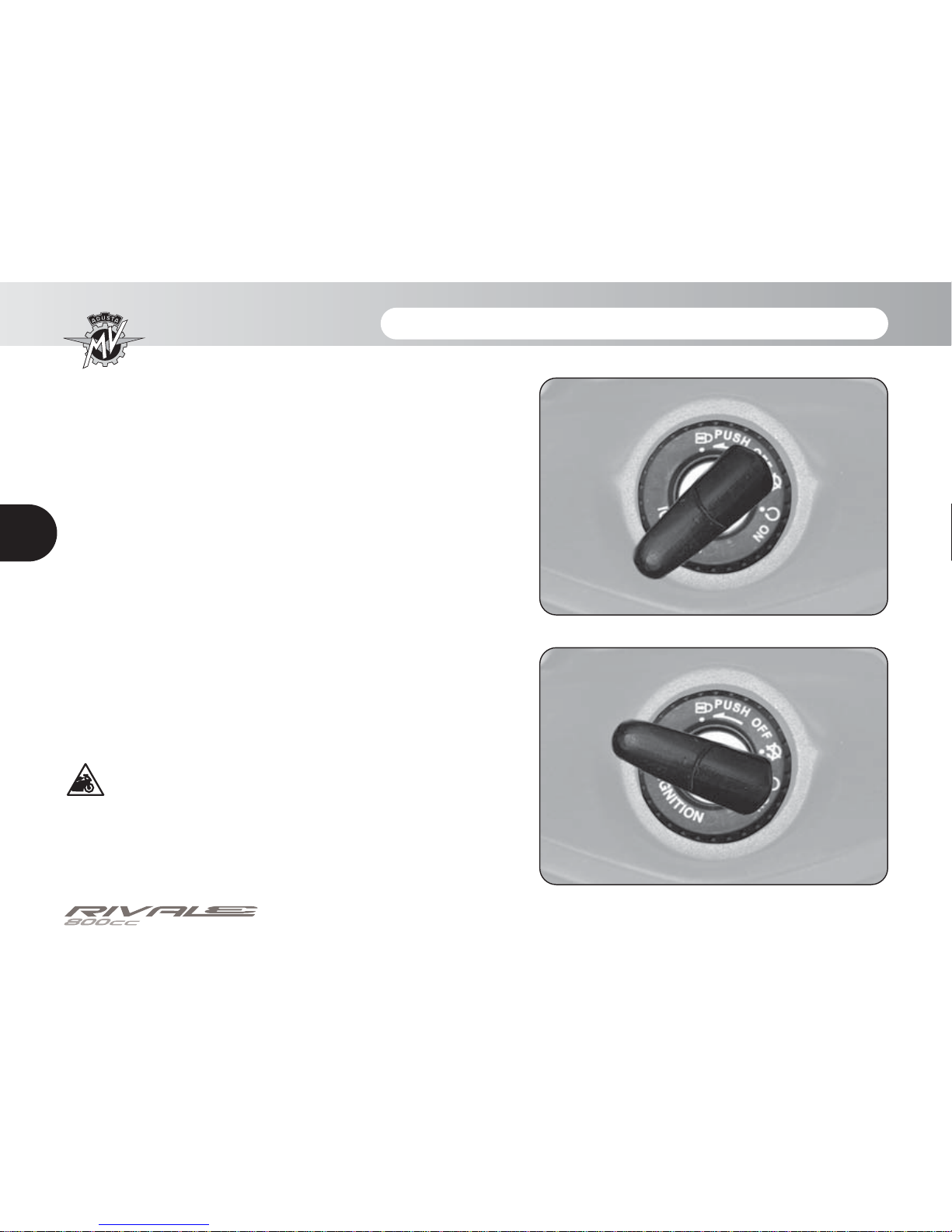
ON position
All electrical circuits are activated. The instruments and
warning lights perform the self-diagnostic cycle. The
engine can be started. The key cannot be removed.
CAUTION
Do not leave the key on the ON position for a
long time when the engine is not running, in
order to avoid damage to the electrical parts
of the motorcycle.
- 23 -
CONTROLS AND INSTRUMENTS 3
3
GB
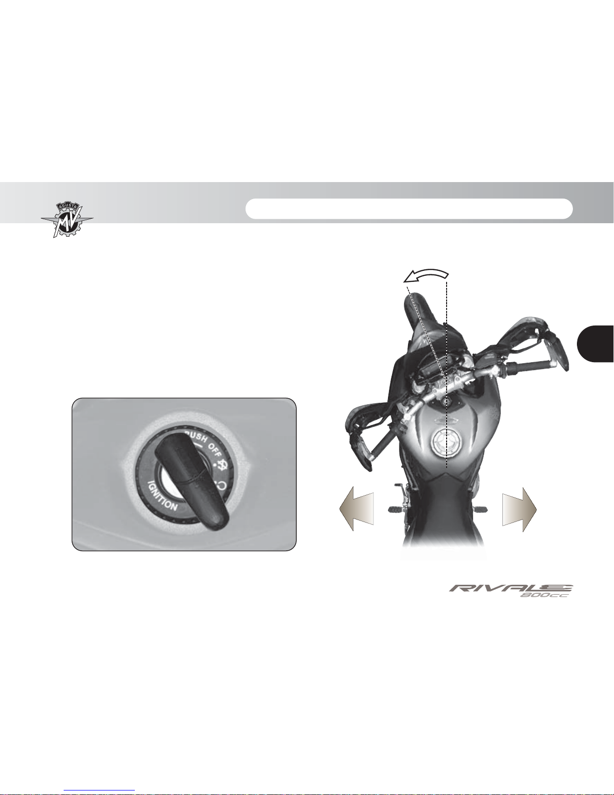
LOCK position
Turn the handlebar to the left or right. Press the key in
gently while rotating it to the LOCK position.
All electrical circuits are deactivated and the steering is
locked. The key can be removed.
Left side
Right side
- 24 -
CONTROLS AND INSTRUMENTS 3
3
GB
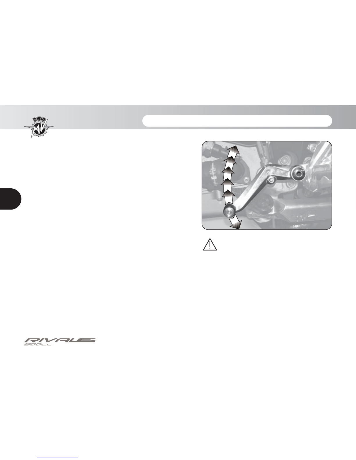
3.6. Gear lever
The N (neutral) position is indicated by the warning light
on the instrument panel.
To change into first gear, push the lever down.
To change into second gear, lift the lever up. Lifting the
lever up repeatedly engages all the other gears in succession up to the sixth speed.
“Quick Shift” function
The Rivale 800 model is equipped with a “Quick Shift”
gear change system; this device enables you to upshift
without pulling the clutch or changing the throttle control
angle. This way, it is possible to change into upper gears
by keeping a constant acceleration and reducing shifting time to a minimum. The “Quick Shift” system is not
available when you change gear with the clutch lever
pressed or at a speed lower than 30 km/h, nor when
shifting into lower gears.
1°
N
2°
3°
4°
5°
6°
WARNING: When you are riding the
vehicle with the engine revving
high in a low gear, changing gear
without operating the clutch lever
can cause abrupt reactions which
can compromise the stability of the
vehicle. MV Agusta recommends
to operate the clutch lever in these
circumstances, especially when
the engine rpm is close to the rpmlimiter intervention speed.
- 25 -
CONTROLS AND INSTRUMENTS 3
3
GB
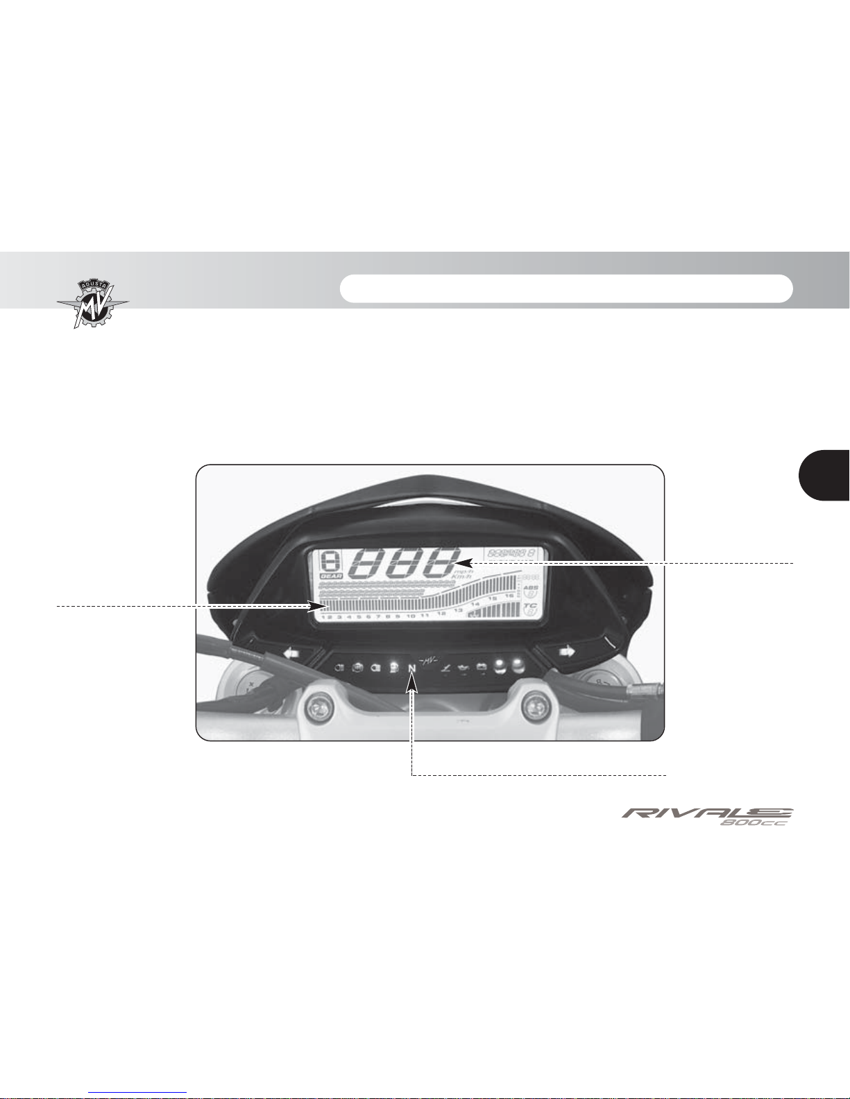
3.7. Instruments and warning lights
The instruments and warning lights are activated by turning the ignition switch
to the ON position. After a preliminary check (approx. 7 seconds) the displayed
information reflects the current general condition of the motorcycle.
Multifunction
display (§3.7.2.)
Warning lights (§3.7.1.)
Tachometer display
- 26 -
CONTROLS AND INSTRUMENTS 3
3
GB
Engine oil pressure warning light (red)
Lights up when the oil pressure is insufficient.
WARNING: If the warning light comes on while riding, stop the motorcycle immediately. Check the oil
level and if necessary have it restored by a MV
Agusta authorized service centre
(see §3.8.). If the warning light
comes on even if the oil level is
correct, do not resume riding and
contact a MV Agusta authorized
service centre.
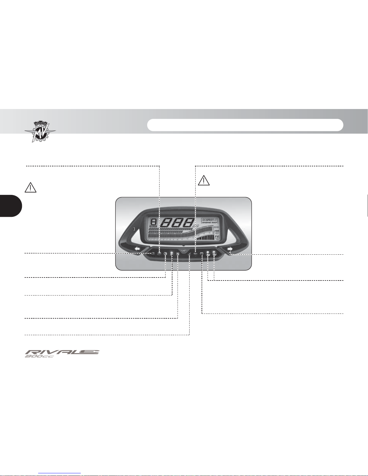
3.7.1. Warning lights
Neutral warning light (green)
It turns on when the gear is in “Neutral”.
Sidestand down warning light (red)
Lights up when the sidestand is down.
Low beam (green)
It turns on when the low beam is on.
High beam (blue)
It turns on when the high beam is
on.
Reserve fuel indicator (orange)
Comes on when approximately 4 litres of fuel
are left.
ABS warning light (orange)
(only on certain models)
Lights up when the ABS system has a fault or is
deactivated, or if the speed is lower than 5 km/h.
WARNING: If the warning light comes on while
riding, stop the motorcycle immediately
and check that the ABS system is activated (see
§4.4.6.). In this case, resume
riding at reduced speed and
contact a MV Agusta authorized service centre.
Battery charge indicator (red)
Lights up when the alternator does not supply
enough current to charge the battery.
If the indicator comes on while riding, contact
an authorized service centre.
Turn indicator lights
(green)
They light up when the turn indicators are activated.
RPM limiter indicators (orange/red)
They switch on before the limiter intervention, at a
number of turns dependent on the ratio of the inserted gear. The limiter intervenes at 13000 rpm.
- 27 -
CONTROLS AND INSTRUMENTS 3
3
GB
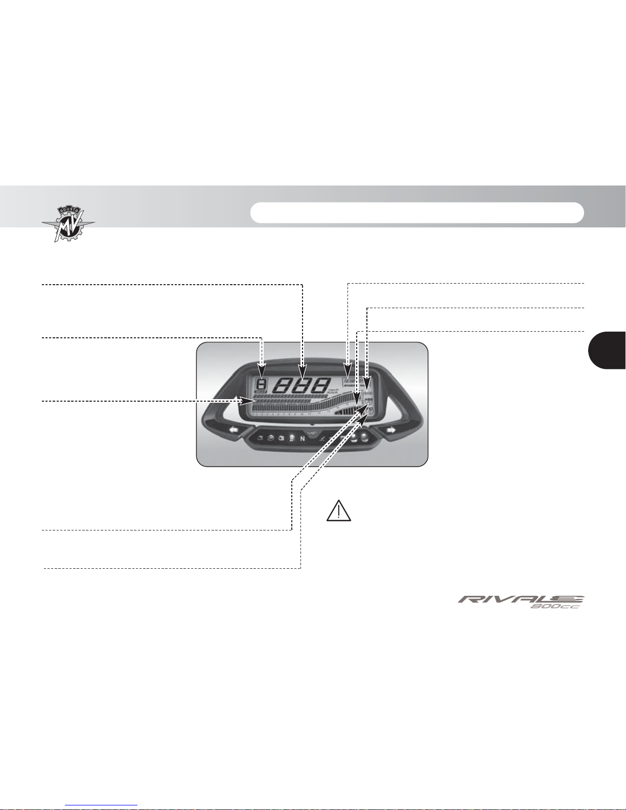
3.7.2. General display
Control unit mapping display
Indicates the control unit mapping currently selected.
“TOTAL” odometer
It displays the total distance covered;
from 0 to 999999 (Km or miles)
Trip counter 1, “TRIP 1”
It displays the length of a trip; from
0 to 999.9 (Km or miles)
Trip counter 2, “TRIP 2”
It displays the length of a trip; from 0 to 999.9 (Km or miles)
Chronometer
It displays the time measured by the chronometer
Thermometer
It displays the temperature of the
coolant by turning on a variable
number of segments on a graduated scale. When the temperature
falls outside the normal operating
range, it may display one of the
following information:
- the display shows just one blinking segment; it means that the
temperature is low;
- all segments are on, while the
upper segment is blinking; it
means that the temperature is
high.
Danger - Notice: if the temperature is high, stop
the motorbike and check the coolant level. If it
needs to be filled up, contact a MV Agusta licensed
service centre (see § 3.8). If the warning light turns
on even if the level is adequate, stop driving and
contact a MV Agusta licensed service centre.
Gear display
It displays the currently engaged
gear. The “0” digit stands for “neutral”.
Speedometer
It displays the speed of the motorbike. It can be given
in kilometres per hour (Km/h) or in miles per hour
(Mph). The full scale measures 300 Km/h (186 Mph).
Clock
Indicates the current time.
ABS display
(only on certain models)
Indicates the activation state of the ABS function.
Traction control level display
Indicates the traction control level currently selected.
 Loading...