

MV Agusta F4 1000 S, FT, R, RR Workshop Manual

©2011
Die auch nur teilweise Wiedergabe dieser Unterlagen ohne schriftliche Zustimmung von Seiten der Fa. MV Agusta S.p.A. ist verboten.
Teil N° 8C00B4302 - Zweite Ausgabe
Im März 2011 gedruckt
Engine workshop manual
MV AGUSTA F4 1000 S - FT - R - RR
- 2 -
Statement
This manual, to be used by the MV Agusta authorised workshops has been realised with
the purpose of assisting authorised personnel in maintenance and repairs operations of
the motorcycle. The knowledge of technical data herein noted, determines the complete
professional training of the technician. With purpose of making the reading of this manual
immediately comprehensible, the paragraphs have been aligned with detailed illustrations
that highlight the argument dealt with.
Useful advice
To prevent any problems and to reach an excellent final result, MV Agusta recommend
skeeping to the following guidelines:
-In the case of an eventual repair, evaluate the client’s impressions who states that there
is an abnormal functioning of the motorcycle and to formulate the right questions to
clarify the symptoms of the problem.
-Clearly diagnose the cause of the abnormality. The basic fundamental theories can be
absorbed by reading this manual that must necessarily be integrated to the personal
experience and the participation of training courses that are periodically organised by
MV Agusta.
-Rationally plan the repair to avoid slack periods, e.g. the collection of spare parts, the
preparation of tools and equipment, etc.
-To reach the part to be repaired limiting the work to the essential operations. With
regards to this, a valid help would be to consult this manual with regards to the
sequences of removal demonstrated in this manual.
Informative note
MV Agusta S.p.A. is committed to a policy of continuous improvement of their products. For
this reason, there could be slight differences between that which is written here and the
motorcycle on which repairs and/or maintenance are about to be carried out. MV Agusta
models are exported to many countries where different norms in relation to the highway code
and homologation procedures are valid. Hoping that you will comprehend these problems,
MV Agusta S.p.A. reserves the right to make modifications to its products and technical
documentation at any moment and without prior announcement.
Respect and defend the environment
Everything that we do has repercussions on the entire planet and its resources. MV Agusta,
wanting to protect the interest of the people, would like to make the client and the technicians
of the technical assistance centres aware and to adopt modalities of use of the motorcycle
and the disposure of its parts in full respect of the norms in force in terms of environmental
pollution, disposal and the recycling of waste.

- 3 -
General index
GENERAL DESCRIPTION................................................................. A
MAINTENANCE................................................................................. B
CYLINDER KIT.................................................................................. C
CYLINDER BLOCK........................................................................... D
LUBRICATION................................................................................... E
ELECTRICAL COMPONENTS.......................................................... F
TIGHTENING TORQUES................................................................... G
SPECIAL TOOLS.............................................................................. H
ANALYTICAL INDEX......................................................................... I
Rev. 0
Rev. 1
Rev. 1
Rev. 1
Rev. 1
Rev. 0
Rev. 0
Rev. 0
Rev. 0


SECTION
REVISION 0
A
- 1 -
General description
A

- 2 -
General description
A
SUMMARY
HOW TO CONSULT THIS MANUAL......................................................................................Page 3
THE PURPOSE OF THIS MANUAL.......................................................................................Page 3
GLOSSARYAND SYMBOLS..................................................................................................Page 4
RIGHT HAND AND LEFT HAND STANDARD........................................................................Page 6
SAFETY.................................................................................................................................Page 7
OBSERVATIONS....................................................................................................................Page 9
INDEX....................................................................................................................................Page 9
OPERATIVE TECHNICALSPECIFICATIONS.........................................................................Page 10

- 3 -
General description
A
HOW TO CONSULT THIS MANUAL
Order of the subjects
This manual is divided into chapters that deal with the
sub-groups of the motorcycle. To quickly find the chapter
required, the pages of each chapter are marked with a
reference mark aligned to the relative item in the general
index.
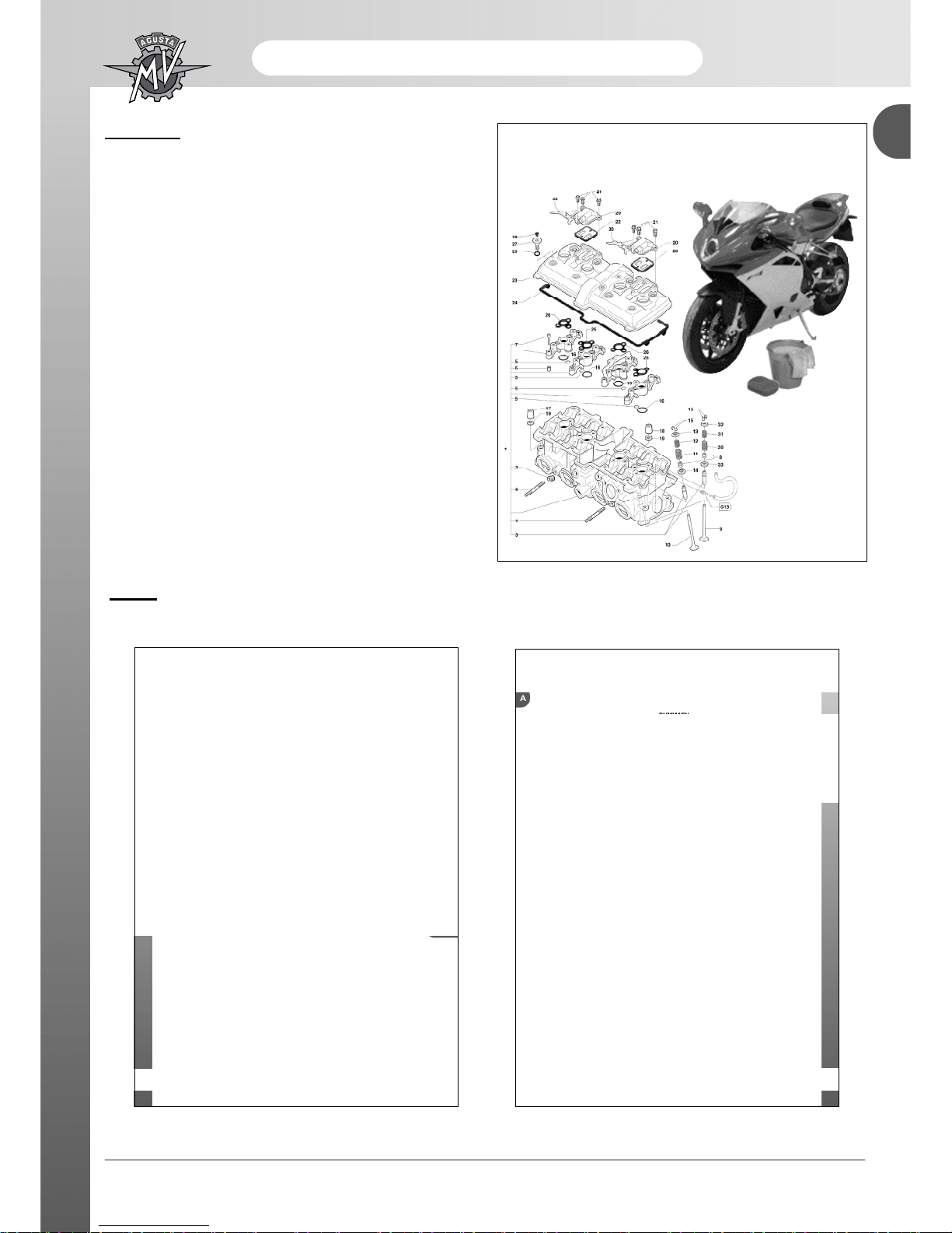
Display of the operations
The operations of disassembly, assembly, removal and
control are presented with the help of illustrations
(designs and photographs).The illustrations contain
symbols that indicate the procedure, special tools and
other information. See the symbols lists for their
significance. The procedures are described step after
step.
EXAMPLE
Steering pin tightening
Screw in the steering pin flange ring, without tightening.
This operation must be done manually.
Check that the steering base is at the end of its travel,
to the right. Using the special tool N. 800091645, tighten
the ring (1) by rotating it 10°calculated approximately
as one third of the movement between the two holes of
the ring (2) of the steering head (see the figure).
PURPOSE OF THE MANUAL
Principally, this manual has been written for MV Agusta dealers and qualified mechanics. It is not possible to
document all the knowledge necessary for a mechanic in a manual. Those who utilise it must have a basic
knowledge of mechanical concepts and the inherent procedures in the techniques of repairing motorcycles.
Without this knowledge, the maintenance and repair operations can render the motorcycle unsafe for use.
Updates
MV Agusta S.p.A. is committed to a policy of continuous updating of the models produced. The modifications and
significant changes to the specifications and the procedures will be communicated to the official dealers and will
appear in future editions of this manual. All information, instructions and technical data included in this manual are
based upon information on the product updated at the moment of going to print. MV Agusta S.p.A. reserves the
right to carry out changes at any moment without prior notice and without incurring any obligation.

- 4 -
General description
A
ATTENTION
WARNING
This signifies that the lack or
the incomplete observance
of this advice can be gravely
dangerous for your safety
and for the safety of other
persons.
This signifies that the lack of
observance of these
instructions can bring the risk
of damage to the motorcycle
and the equipment.
During this kind of procedure
inflammable vapours might develop
and metallic parts might be expelled
at high velocity. Thus, it is necessary
to:
- work far from exposed flames and
sparks;
- wear protective clothing;
- wear protective eye-glasses.
In case it should be necessary, due to
wear, to substitute a particular, relative
to a cylinder, we strongly suggest that
you check and if necessary, substitute
the same particular in all of the
cylinders for more satisfying results.In
particular, we recommend that at the
same time you substitute:
- pistons with relative elastic bands
and piston pins;
- valves with relative springs, semicones,disks and grazings;
- Valve guides with relative valves,
springs, semi-cones and grazings;
- bed bearing;
- whatever else under goes uniform
wear, a side from the position of the
relative cylinder.
In order to allow the motorto function
under the best conditions, it is
necessary that all of the couplings are
within the accepted tolerances
established. A tight coupling, is in fact,
cause for seizure as soon as the
organs in motion begin to heat, while
a loose coupling is cause for vibrations
which accelerates wear on the
particulars in motion.
GLOSSARY AND SYMBOLS
- 5 -
General description
A
Supplies key information for the best
fulfilment of the operation.
Utilise a specific tool or equipment for
the correct carrying out of the operation
described.
Tighten to the specified torque.
Tolerance or limit of use.
Utilise the tester.
Use the recommended oil.
Use the recommended grease.
Use the recommended brake fluid.
Use the recommended suspension
fluid.
Use the recommended coolant.
Use the recommended thread-locking
fluid.
Use the recommended sealant.
Use the recommended adhesive.
Carry out accurate cleaning.
Use new components.
Substitute the component.
Do not leave litter about.
NOTE
All of the countersigns indicting right, left,
superior, inferior, front and back, refer to the
motor-bike in the normal direction of march.
The motor supports numbering of the cylinders
and of the attached components, increases
moving from left towards right in regards to the
direction of march.
This symbol indicates "the procedures
to be carried out with an empty cooling
circuit".
- 6 -
General description
A
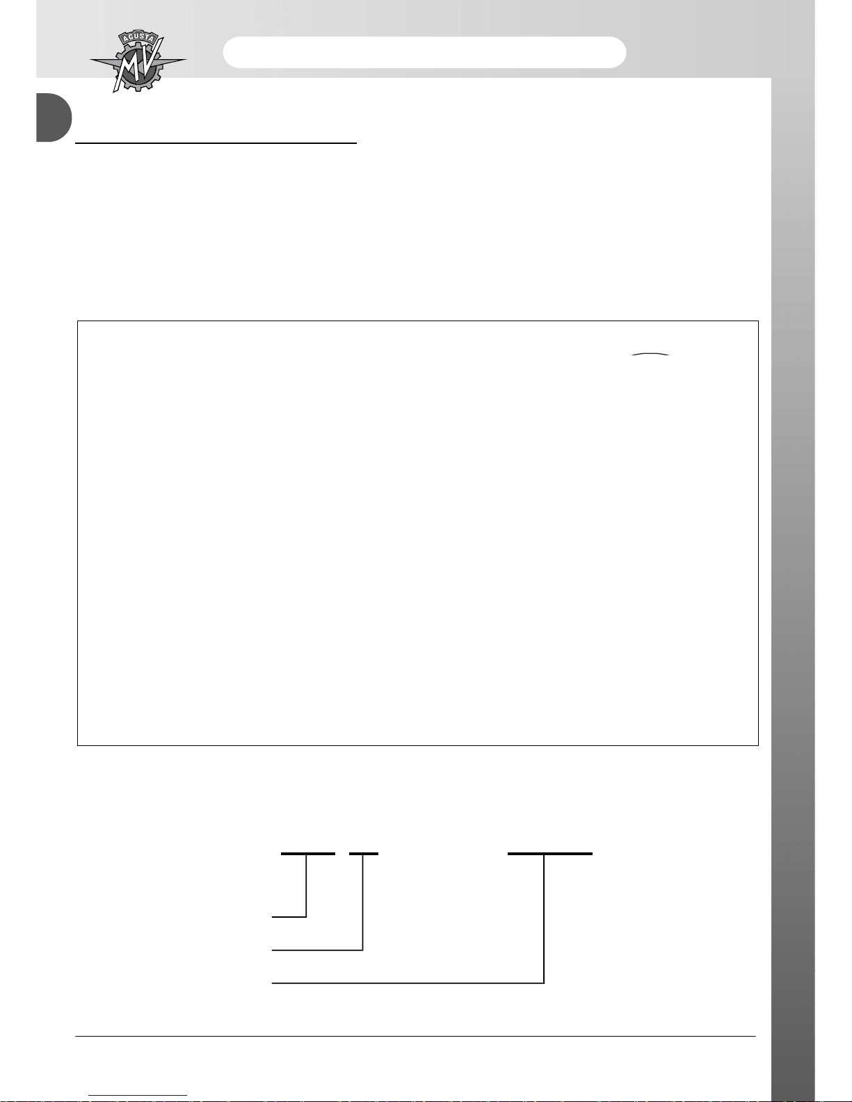
RIGHT HAND AND LEFT HAND STANDARD
To clarify the right hand and left hand standard that is used in this manual, herewith below is a diagram of the
motorcycle and the engine against which are indicated the right and left sides.
Cylinder 1
Cylinder 2
Cylinder 3
Cylinder 4
Rh Side
Rh Side
Lh Side
Lh Side

- 7 -
General description
A
SAFETY
The information contained in this paragraph is fundamental so that the operations
carriedout on the motorcycle can be conducted with minimum risk to the mechanic.
Carbon Monoxide
•Exhaust gases contain carbon monoxide (CO) that is poisonous. Carbon monoxide can cause the loss of
consciousness and death.
•If it is necessary to switch on the engine, check that the environment is well ventilated. Never switch on the
engine in an enclosed environment.
•Switching on the engine can only be carried out in an enclosed environment when there are the appropriate
devices for the evacuation of exhaust gases.
Petrol
•Petrol is extremely inflammable and under certain conditions can be explosive.
•Keep sources of heat, sparks and flames away from the work area.
•Always work in a well-ventilated area.
•Never use petrol as a cleaning solvent. Generally, avoid handling it unless it is absolutely necessary.
•Do not use petrol for cleaning components by using compressed air.
•Keep petrol out of reach of children.
Engine oil
•Engine oil can cause skin illnesses if in constant and long contact with the skin.
•If the skin comes into contact with engine oil, wash the parts affected as soon as possible with soap and water.
•If engine oil comes into contact with the eyes, rinse abundantly with water and seek medical attention.
•If engine oil is swallowed, do not provocate vomiting to avoid the aspiration of the product into the lungs.
Transport the injured person immediately to hospital.
•Used oil contains dangerous substances and poisonous for the environment. To substitute oil, it is necessary
to be equipped to deal with the collection of used oil in respect of the norms in force.
•Do not dispose of used oil in the environment.
•Keep used oil out of the reach of children.
Engine coolant
•Under certain situations, the ethylene glycol contained in the engine coolant is inflammable and its flame is
invisible. Ethylene glycol would cause serious burns if ignited because it is invisible.
•Avoid bringing the engine coolant into contact with hot parts. Such parts could be sufficiently hot to ignite the
coolant.
•The engine coolant (ethylene glycol) can cause irritation of the skin and is poisonous if swallowed.
•If the engine coolant comes into contact with the skin, immediately remove any contaminated clothing and
wash with soap and water. If it comes into contact with the eyes, abundantly rinse with clean water and
immediately consult a doctor. If swallowed, do not provocate vomiting to avoid the aspiration of the product
into the lungs. Administer clean water and transport the injured person immediately to hospital and show the
product to a doctor.
•If exposed to high concentrations of vapour, transport the injured person to a non-poisonous atmosphere and if
necessary call a doctor.
•Do not remove the radiator cap when the engine is still hot. Being under pressure, the engine coolant can be
violently ejected and therefore provocate burns.
•The engine coolant contains dangerous and poisonous substances and is therefore dangerous for the
environment. To substitute used engine coolant, it is necessary to be equipped to deal with the collection of
used oil/of used engine coolant in respect of the norms in force.
•Do not dispose of engine coolant in the environment.
•Keep engine coolant out of reach of children.
ATTENTION

- 8 -
General description
A
Brake fluid
•Brake fluid is extremely corrosive.
•Avoid any contacts with the eyes, skin and the mucous membrane.
•If brake liquid comes into contact with the skin, remove all contaminated clothing and wash immediately with
soap and water.
•If brake fluid comes into contact with the eyes, abundantly rinse with water and call a doctor.
•If swallowed, do not provocate vomiting to avoid aspiration of the product into the lungs. Immediately call a
doctor.
•Take the injured person immediately to hospital, if he has breathed brake fluid into the lungs.
•In the case of exposure to high concentrations of vapour, move the injured person to a non-poisonous
atmosphereand if necessary call a doctor.
•In the case of accidental contact, rinse abundantly with water and call a doctor.
•Keep brake fluid out of reach of children.
Thread-locking fluid
•As it is not classified as dangerous, the prolonged contact with the skin, particularly with regards to abrasions can
provocate sensitiveness and dermatitis. In the case of contact with the skin, rinse abundantly with running water.
•Move the injured person into the open air and call a doctor if the injured person feels ill after having breathed in
the product.
•In the case of contact with the eyes, rinse abundantly with water for at least 15 minutes.
•If the thread-locking fluid has been swallowed, drink an abundant quantity of water or milk. Do not provocate
vomiting to avoid the aspiration of the product into the lungs. Immediately call a doctor.
•Keep out of reach of children.
Nitrogen - rear shock absorber
•The rear shock absorber contains nitrogen under pressure.
•Before disposing of used shock absorbers, discharge the nitrogen via the depressurising valve.
•Utilise only nitrogen to pressurise the shock absorber. The use of unstable gases can cause explosions that could
cause burns.
•Do not place the shock absorber near to flames or sources of heat as this could cause explosions with consequent
burns.
•Keep out of reach of children.
Battery
•The battery produces explosive gases. Keep it away from sparks, flames or cigarettes. During recharging,
adequately ventilate the environment.
•The battery contains a solution of sulphuric acid (electrolyte).
•Sulphuric acid is corrosive and it destroys many materials and clothing. On contact with small quantities of water
it generates a violent reaction that manifests itself by creating large quantity of heat and spurts of hot acid.
Sulphuric acid attacks many metals thereby liberating hydrogen: an inflammable gas that forms an explosive
mixture when mixed with air.
•Contact with sulphuric acid can cause burns. In the case of contact, remove immediately all contaminated clothing
and wash the skin with abundant quantities of water. Take the injured person to hospital if necessary.
•In the case of contact with the eyes, rinse immediately with abundant water. Call a doctor and continue with the
treatment until the doctor arrives.
•If the electrolyte is swallowed, rinse the mouth with water without swallowing. Take the injured person immediately
to hospital and explain to the doctor there what the injured person has swallowed.
•The battery contains dangerous substances that are poisonous for the environment. It is necessary to be equipped
to dispose of this product in respect of the norms in force.
•Do not dispose of used batteries in the environment.
•Keep out of reach of children.
Hot parts
•The engine and the exhaust system become very hot and maintain this temperature for some time after the
engine has been switched off. Wait for these parts to cool down before handling them or working on the motorcycle
near to them. Use protective gloves.
- 9 -
General description
A
WARNING
The information contained in thisparagraph is important
so that the operations carried out on the motorcycle can
be conducted without damaging the motorcycle.
• Thoroughly clean the motorcycle before
disassembling it.
• During disassembly, clean all parts and place them
in containers respecting exactly the order of
disassembly.
• Always use the special utensils where necessary
andeach time where prescribed.
• Always use adhesives, sealants and lubricants where
prescribed. Respect the instructions about their
technicalcharacteristics.
• Always substitute parts such as gaskets, O-rings,
securitywashers with new parts.
• Slackening or tightening nuts or screws, always start
withthose of a greater dimension or from the centre.
Alwaysrespect the torque values indicated.
• Utilise only MV Agusta spare parts.
INDEX
GENERAL INDEX SUMMARY OF EACH CHAPTER
- 10 -
General description
A
OPERATIVE TECHNICAL SPECIFICATIONS
MOTORCYCLE IDENTIFICATION
The registration number of the motorcycle is stamped on the right side of the steering head.The engine
registration number is stamped on the upper engine casing, near the forks.
Below is an example of the designation of the frame registration number:
Manufacturer identification
Vehicle model
Progressive frame number
2) Engine registration number
1) Frame
registration
number
3) Homologation data
ZCG F6 10 AA Y V 000001

SECTION
REVISION 1
B
- 1 -
Maintenance
B

- 2 -
Maintenance
B
SUMMARY
PLANNED MAINTENANCE SCHEDULE................................................................................Page 3
THROTTLE BODY ADJUSTMENT AND TUNING..................................................................Page 11
- 3 -
Maintenance
B
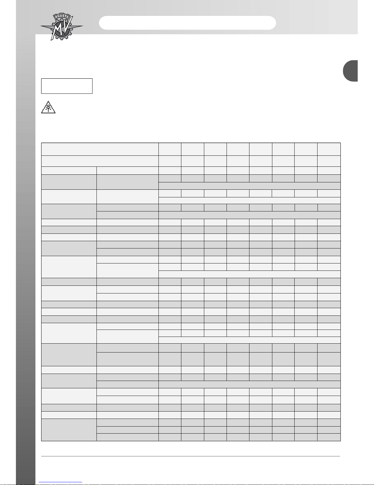
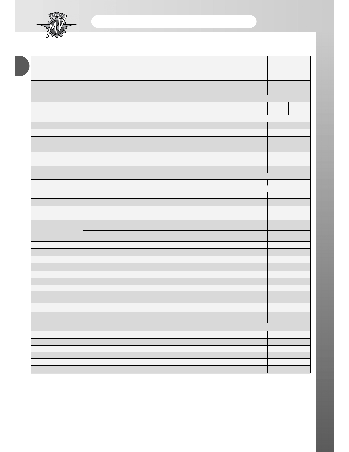
PLANNED MAINTENANCE SCHEDULE
The following diagram shows the recommended planned maintenance intervals. Periodic maintenance is essen-tial
to keep the vehicle in perfect running order and to ensure optimum cost efficiency.
Use shorter maintenance intervals if the vehicle is used in particularly harsh conditions.
Let us help protect the environment
Everything we do affects the entire planet and its resources. To protect the common interest, MV Agustaurges
its customers and service operators to use the vehicles and dispose of their components in com-pliance with
applicable regulations on environmental pollution control, waste disposal and recycling.
Programmed maintenance schedule
0 1000 6000 12000 18000 24000 30000 36000
Km (ml) covered
(600) (3800) (7500) (11200) (14900) (18600) (22400)
Service
pre-
A B C D E F G
delivery
Description Operation
. . . . . . .
Engine oil Substitution
At least once a year
Substitution
. . . . . . .
Engine oil filter (utilize only MV Agusta
original oil filter) At every substitution of engine oil
Check level / Top up . . . . . . . .
Engine coolant
Substitution every 2 years
Cooling Check for leakages . . . . . . . .
Electric fan Check functioning . . . . . . . .
Valves Check / adjustment . . .
Check . .
Timing chain
Substitution .
Check / Substitution . .
Timing movable pad .
Substitution
At least every substitution of the timing chain
Timing chain tensioner Check / Substitution . . .
Check / Substitution . . .
Spark plugs
Substitution . . .
Fuel filter Check / Substitution . . .
Throttle body Check and adjustment . . . . . . .
Air filter Check / Substitution . . . . . .
Check level . . . . . . .
Brake and clutch fluid .
Substitution
every 2 years
Check Functioning and Circuit . . . . . . . .
Brake / Clutch
Cleaning of contact lever and
. . . . . . . .
pump piston area
Brake pads (front and rear) Check / Substitution . . . . . . .
Check for defects and leakages . . .
Fuel tubes
Substitution every 3 years
Check functioning . . . . . . . .
Accelerator control
Verify / adjust play . . . . . . . .
Starter control Check functioning . . . . . . . .
Transmission / flexible controls
Check / Adjustment . . . . . . . .
Check / Adjustment . . . . . . . .
Transmission chain Lubricate . . . .
Substitution . . .
WARNING
- 4 -
Maintenance
B
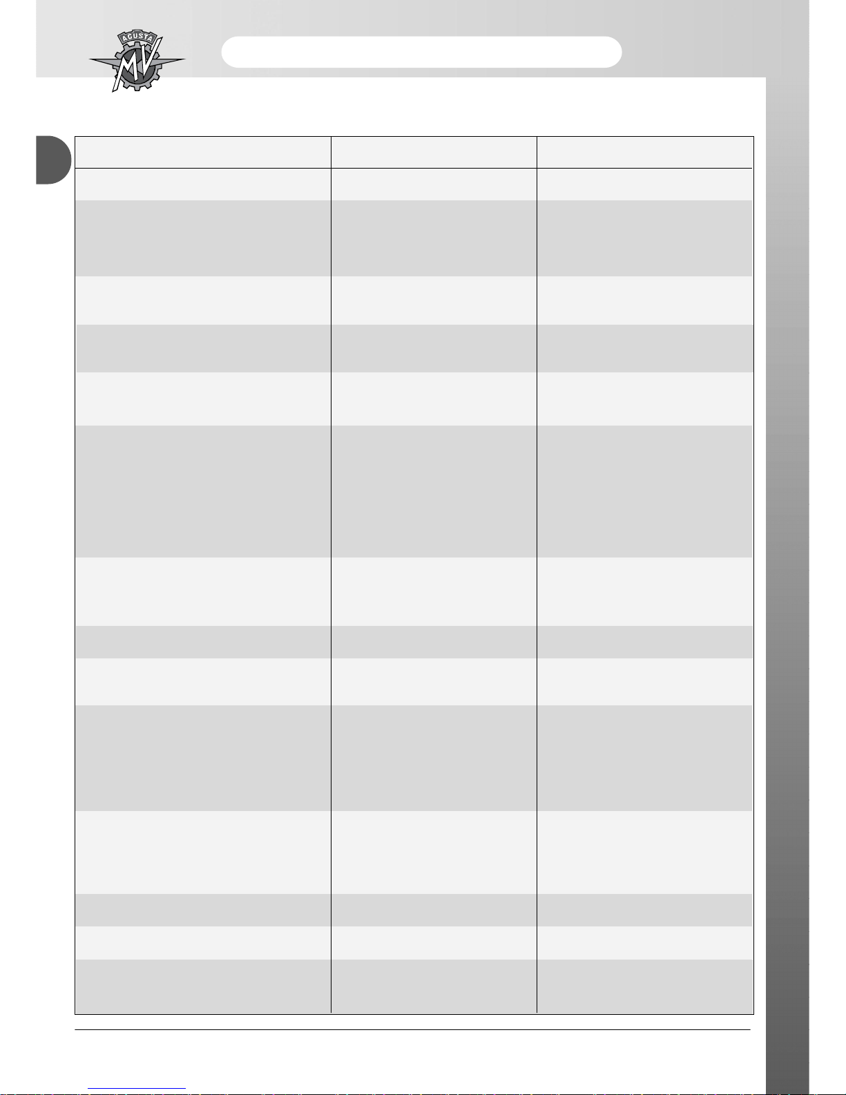
Programmed maintenance schedule
0 1000 6000 12000 18000 24000 30000 36000
Km (ml) covered
(600) (3800) (7500) (11200) (14900) (18600) (22400)
Service
pre-
A B C D E F G
delivery
Check . . . .
Pinion wheel / Stop washer . . .
Substitution
At least at each substitution of the transmission chain
Check . . . .
Crown wheel . . .
Substitution
At least at each substitution of the transmission chain
Crown wheel tension regulator
Check / Substitution . . .
Steering head flange ring Check / Adjustment . . . .
Check / Adjustment . . . .
Steering bearings
Lubrication .
Check for pressure . . . . . . . .
Tyres
Check for wear . . . . . . .
. . . . . . . .
Wheel rims Visual check
Every tyre substitution
. . . . .
Front wheel bearings
Check
Every tyre substitution
Substitution .
Side stand Check functioning . . . . . . . .
Check functioning . . . . . . . .
Side stand switch
Substitution . . . . . . . .
Check / Lubricate
. .
Rear wheel hub
roller bearings and guide
Substitution / Lubricate
.
roller bearings and guide
Rear fork bearings Check / Lubrication .
Chain guide frame plate Check / Adjustment . . . . . . .
Rear shock absorber Check / Adjustment . . . .
Front fork oil Substitution .
Battery connections Check and clean . . . . . . .
Electrical system Check functioning . . . . . . . .
instruments Check functioning . . . . . . . .
Lights / Visual signals
Check functioning
. . . . . . . .
bulb replacement
Horn Check functioning . . . . . . . .
Check functioning
. . . . . . . .
Front headlight
bulb replacement
Adjust at every variation of riding set-up of the motorcycles
Ignition switch Check functioning . . . . . . . .
Locks Check functioning . . . . . . . .
Torque settings - nuts and bolt
Check / Tightness . . . . . . . .
Tube band fasteners Check / Tightness . . . . . . . .
General lubrication . . . . . . . .
General check . . . . . . . .

- 5 -
Maintenance
B
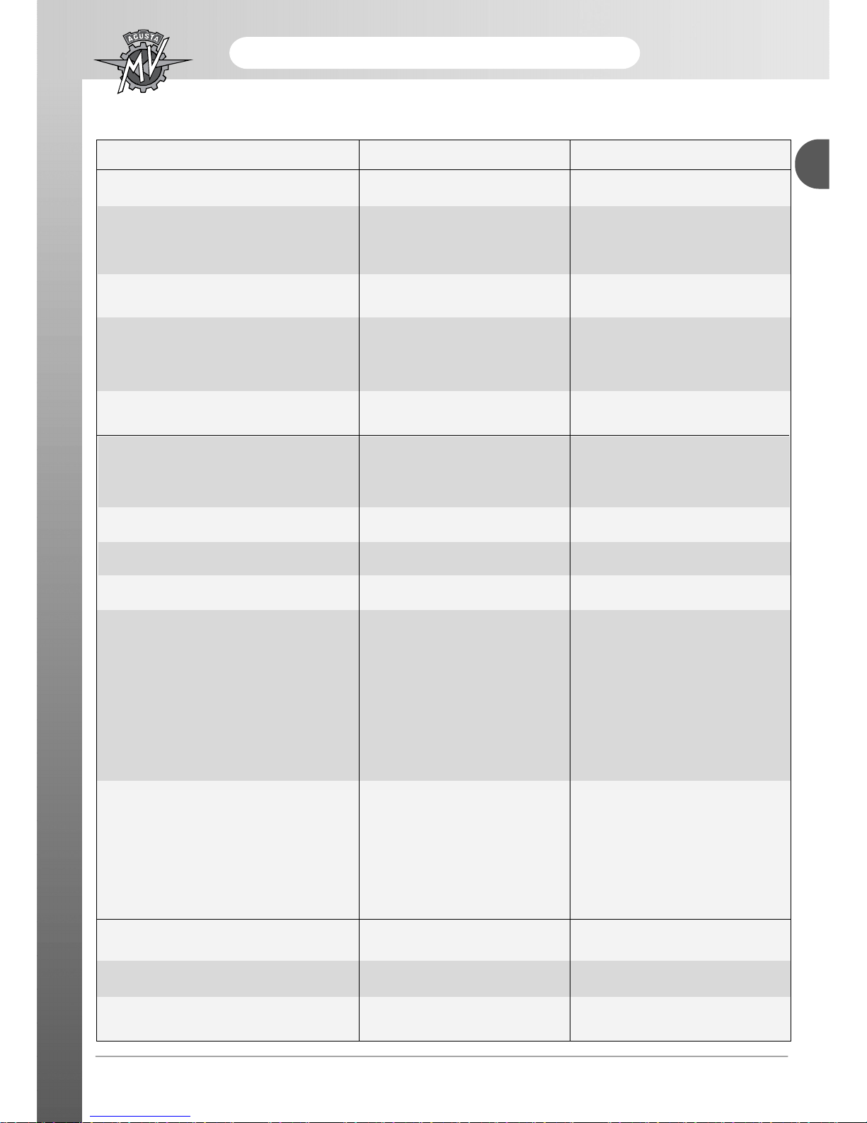
Description Recommended product Specification
Engine lubrication oil AGIP RACING 4T 10W/60 (*) API SJ SAE 10W/60
Ethylene - Glycol
Engine coolant AGIP ECO PERMANENT Diluited with 40 %
of Distilled Water
Clutch and brake fluid AGIP BRAKE FLUID DOT 4 DOT 4
Chain lubrication oil MOTUL CHAIN LUBE ROAD -
Table of lubricants and fluids
*To find the recommended product, MV Agusta suggests going directly to the authorised MV Agusta dealers.
AGIP Racing 4T10W/60 has been manufactured for the F4 engine. If the described oil is not available, MV
NOTE
The above specifications indicated are marked either on
their own or together with others on the container of the
lubricating oil.
Agusta suggests using completely synthetic oils with characteristics
that conform or exceed the following norms:
– Conforming to API SJ
– Conforming to ACEA A3
– Conforming to JASO MA
– Grade SAE 20 W-50 or 10 W-60
Engine Oil
SAE 10 W-60
API SJ
ACE AA3
JASO MA
- 6 -
Maintenance
B
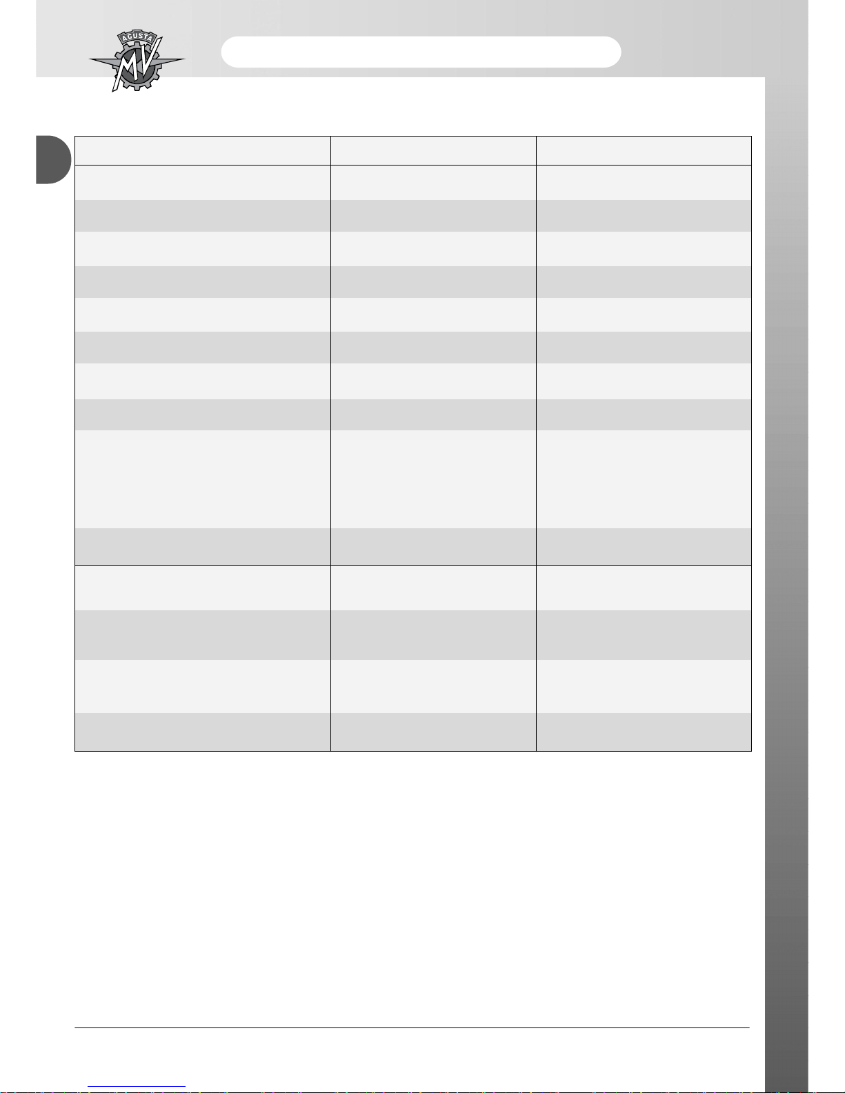
ITEM STANDARD WEAR LIMIT
VALVES
Ø Sealing external diameter
+0,3
Exhaust (F4 M.Y. 2010).......... 24,6 mm
0
+0,3
(F4 M.Y. 2011).......... 25,6 mm
0
+0,3
Inlet (F4 M.Y. 2010).......... 29,8 mm
0
+0,3
(F4 M.Y. 2011).......... 31,6 mm
0
Sealing face thickness
+0,3
Exhaust.............................................. 0,9 mm
0
+0,3
Inlet....................................... 0,7 mm
0
Stem - Guide clearance
Exhaust.............................................. 0,02 ÷ 0,04 mm......................... Coupling: 0,10 mm
Inlet.................................................... 0,01 ÷ 0.03 mm......................... Coupling: 0,08 mm
+0
Ø interno guida................................... 4,5 mm............................ 4,55 mm
+0,012
Valve stem
Exhaust.............................................. 4,4725 ± 0,0075 mm................. 4,4425 mm
Inlet.................................................... 4,4825 ± 0,0075 mm................. 4,4525 mm
Exhaust Valve Spring :
Internal (F4 M.Y. 2010).......... 33,8 mm.................................... 33,3 mm
(F4 M.Y. 2011).......... 38,7 mm.................................... 38,2 mm
External (F4 M.Y. 2010).......... 37,9 mm.................................... 37,4 mm
(F4 M.Y. 2011).......... 40,3 mm.................................... 39,8 mm
- 7 -
Maintenance
B
ITEM STANDARD WEAR LIMIT
VALVES
Inlet Valve Spring:
Internal............................................... 40,2 mm.................................... 39,7 mm
External.............................................. 41,7 mm.................................... 41,2 mm
Valve - Cam clearance
Exhaust.............................................. 0,20 ÷ 0,29 mm
Inlet.................................................... 0,15 ÷ 0,24 mm
CYLINDER AND PISTONS
Piston ovalization............................... .................................................. 0,015 mm
Piston-Cylinder play............................ 0,038 ÷ 0,067 mm..................... 0,10 mm
Piston-Pin play.................................... 0,004 ÷ 0,012 mm..................... 0,03 mm
Wrist pin-Connecting rod clearance... 0,015 ÷ 0,032 mm..................... 0,06 mm
Piston ring width
-0,01
1° segment....................................... 0,8 mm............................... 0,75 mm
-0,03
0
2° segment....................................... 0,8 mm............................... 0,75 mm
-0,02
-0,03
Oil scraper........................................ 1,5 mm............................... 1,38 mm
-0,08
Maximum piston ring-cylinder clearance
1° segment....................................... 0,2 ÷ 0,4 mm............................. 0,6 mm
2° segment....................................... 0,2 ÷ 0,4 mm............................. 0,6 mm
Oil scraper........................................ 0,2 ÷ 0,7 mm............................. 1 mm
CLUTCH
Friction drive plate thickness.............. 3 mm......................................... 2,8 mm
Springs (free lenght).......................... 41 mm....................................... 39 mm
- 8 -
Maintenance
B
ITEM STANDARD WEAR LIMIT
GEAR SHIFT
Gear fork - Groove pivot play.................. 0,35 ÷ 0,15 mm......................... 0,65 mm
Shift drum groove width.......................... 7,05 ÷ 7,15 mm......................... 7,35 mm
Ø Fork pivot............................................ 6,8 ÷ 6,9 mm............................. 6,7 mm
Minimun idle gear axial play................... 0,10 mm
Maximum gear fork play.......................... .................................................. 0,70 mm
Primary gear limit.................................... .................................................. 5,60 mm
Secondary gear limit............................... .................................................. 4,60 mm
Fork selection gear limit
Primary (5a - 6a).................................. .................................................. 4,65 mm
Secondary (1a - 2a, 3a - 4a)................ .................................................. 3,65 mm
Fork - Pit play.......................................... 0,2 ÷ 0,3 mm............................. 0,7 mm
CRANKCASE - DRIVE SHAFT
Crankshaft - crankcase plain
bearing clearance................................... 0,014 ÷ 0,044 mm..................... 0,06 mm
Connecting rod - crankshaft plain
bearing clearance................................... 0,030 ÷ 0,050 mm..................... 0,08 mm
Crankshaft axial clearance..................... 0,2 mm

- 9 -
Maintenance
B
Cleaning the parts
All of the parts must be cleaned with special
biodegradable solvents and dried with compressed air.
Proceed with the cleaning process of all the parts before
disassembling them as well as after the particular parts
have been disassembled. Clean each part even before
reassembling.
Connections
In order to allow the motor to function in the best
conditions it is absolutely necessary that all of the
connections meet the standards established by the
manufacturer. A connection with reduced standards
could cause seizing, while a connection with
excessive toleration causes vibrations which
accelerate the wear of the components.
General norms for assembling the parts
For reassembling invert the disassembling procedure,
paying careful attention to the specified procedures.
Gaskets, oil spill protector, metallic locks. Tightening
rings in deformable material and self blocking nuts must
always be substituted. The bearings are dimensioned
for a determined number of working hours. Substitution
is therefore recommended in consideration of the
difficulty in checking wear. The above mentioned is in
addition suggested for dimensional controls of the single
components mentioned in the relative paragraphs. It is
absolutely necessary to carefully clean all of the
components; the bearings and all of the other parts
subject to wear must be lubricated with motor oil before
reassembling. Nuts and screws must be locked to the
pre established torques.
Following are the descriptions of the disassembling,
revision and reassembling procedures of the various
parts and sub parts constituting the motor, in the
finalized sequence of a completely disassembled
motor.
Disassemble the motor from its frame as described in
the relative paragraph; Drain the oil from the oil cup;
Remove the spark plugs covering the openings with
clean rags to avoid small objects (rings, etc.) from
falling into the motor.
- 10 -
Maintenance
B
Measuring compression in the cylinder
The following tools are necessary in order to carry out
this procedure:
Spark plug key: n°800089013
Compression measurer
Adapter for the compression measurer.
A) Heat the motor to the usual functioning temperature
(of regime);
B) Switch off the engine, remove the tank, air box and
spark plugs;
C) Measure cylinder compression.
Drag the motor into rotation by means of the starting
motor with the butterfly valve completely open until
the compression measurer indicator (compression
meter) no longer rises; the compression
measurement obtained is the maximum.
Be sure the battery is completely charged.
Cylinder compression control (280 rpm-min.)
Engine TypeMin Press. (bars)Max Press. (bars)
F4 7,5 14
- Repeat the procedure for the other cylinders.
N.B.:If the compression in the cylinder is lower than
the minimum value of the reported range, check the
following points:
A) carbon deposits on the walls of the combustion
chamber and on the piston ceiling;
B) the head gasket is not of the correct
measurements;
N.B.:If the compression in the cylinder is lower than
the minimum value of the reported range, check the
following points:
A) The seat of one or more valves is damaged and the
valves do not maintain the compression pressure;
B) One or more valves have null functioning play;
C) The piston, cylinder play is excessive;
D) The cylinder head is twisted and/or the head gasket
is damaged;
E) Excessive play between ring and cable.
Before carrying out the compression trial,
accurately check the battery tension since
the compression value which appears is
quite influenced by the rotation velocity of
the motor, and consequently by the battery
tension.
NOTE
NOTE
- 11 -
Maintenance
B
THROTTLE BODY ADJUSTMENT AND TUNING
(Tickover check, CO synchronisation and check)
Check and adjust First 1000 kilometres and
then every 6000 kilometres
The throttle body adjusting should be performed
starting the engine of the motorcycle, therefore you
should use a flue gas exhauster in order to not
saturate the environment with burnt gas. The
following described operations are fundamental for
the correct functioning and the maximum
performance of the engine.
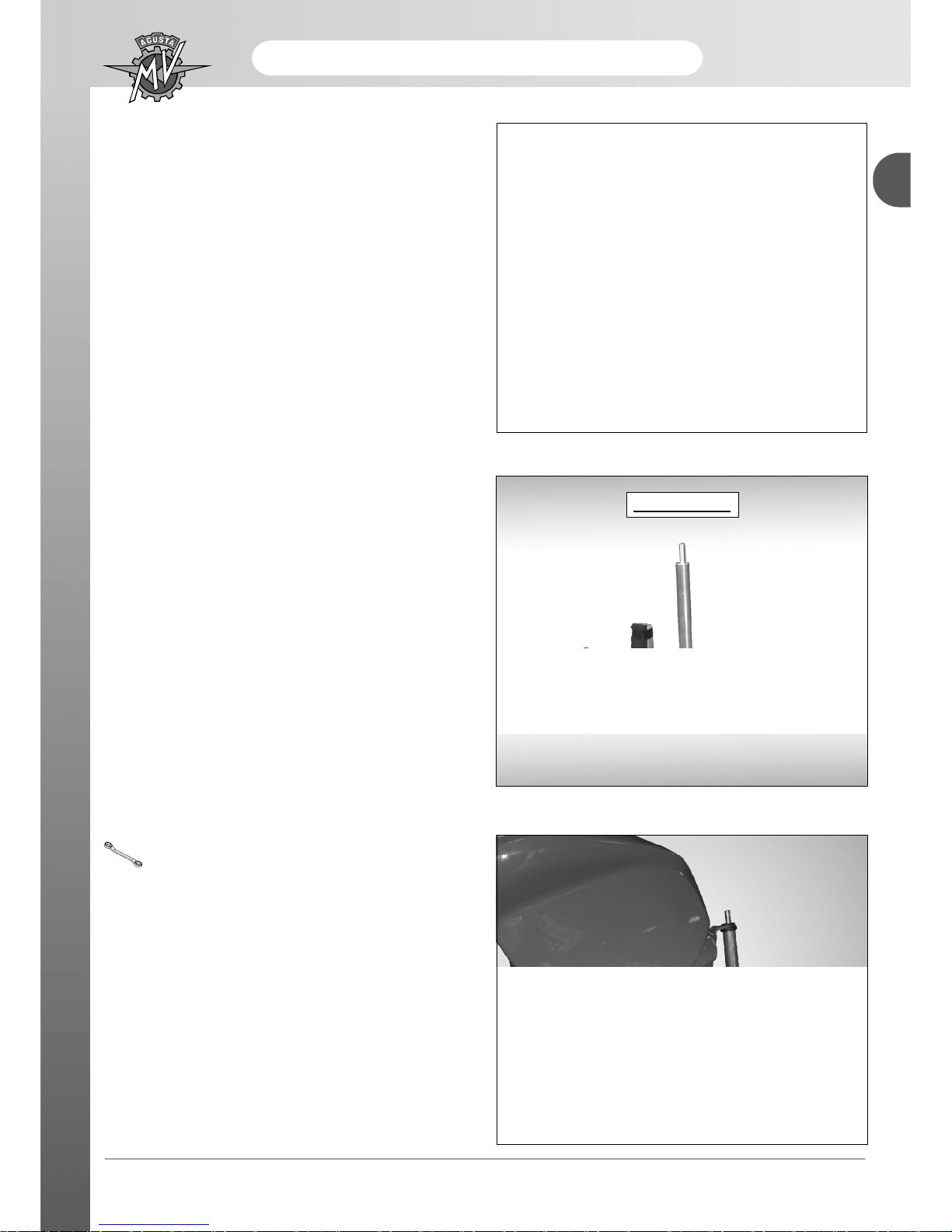
8000B4414
When carrying out operations on throttle bodies, it is
advisable to remove certain parts of the body work such
as:
• Seat
• Tank side panels
• Fuel tank
Attention: before adjusting the throttle body verify
accurately:
- the absence of any cracks or damages on the pipes
to check the depression;
- the absence of gas leakages from drain pipes joint;
- that the fuel pipe unions are not buckled and
crushed.
The motorcycle should be fitted with an auxiliary
support for the tank.
Specific tool: Code 8000B4414

- 12 -
Maintenance
B
Adjustment and calibration of throttle body
After connecting the diagnostic software to the central
unit, before starting the engine check the position of
the throttle valve: 2.3 degrees (min. 1.7, max 2.9).
If it does not fall within the range, use the TPS feature
to reset it, WITHOUT TOUCHING THE MECHANIC
ADJUSTING SCREW OF THE THROTTLE.
From the icon “screwdriver” or from the menù View/
Adjust/Reset errors it is possible to select in the window
TPS the function to reset the throttle position sensor.
Before starting the engine it is necessary to also verify
the position of the exhaust valve: from the window
“Enable/Disable” it is possible to select the command
EXHAUST for the zero resetting of the exhaust valve.
Once you reset the throttle sensor (TPS) and the exhaust
valve (EXHAUST) it is necessary to memorize the new
regulation on the unit positioning the key on “OFF” for
around 20 seconds.
To this point he passes to the levelling of the present
depression in the intake conducts.
Levelling of induction manifold settings
To check this, use a mercury vacuum gauge of the type
shown in the figure. Twist off the plugs that close the
vacuum tubes. The number of the cylinder to which the
rubber plug is connected is written on the same (A).
The vacuum tubes are located on the right and left side
of the vehicle.
Left side: Cylinders 1 and 2
Right side: Cylinders 3 and 4
Connect the measuring device with the rubber pipes.
Each pipe must match the cylinder to which it is
connected.
Then, level the vacuum inside the induction
manifolds, starting the engine to warm it up.
You will see that after starting the engine the Lambda
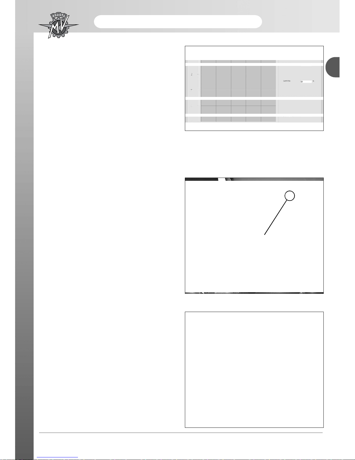
- 13 -
Maintenance
B
channel (mvolt), which was next to zero, will start to rise.
After starting the Lambda control (Lambda % range), the
Lambda (mvolt) will range between a high of 1000 mvolt
and a low of 0 mvolt (minus the diagnostic software lag).
To see the range more clearly, adjust the two graphic
settings. The above behaviour means the Lambda probe
is in working order. Otherwise, if the Lambda (mvolt)
shows a fixed value of about 0 mvolt or 1000 mvolt,
after about thirty seconds, with the Lambda % controller
fixed at -25% or +25%, the system will send out a
‘Lambda probe voltage’ alarm. In this case, check the
electric connection between the Lambda probe and the
system or replace the Lambda probe.
To align the throttle body, use the diagnostic software.
For the engine to work properly, adjust the throttle
body so that the idling regime control works at “midrange”.
All bypass adjusting screws (1) must first be opened by
turning them 1.5 turns off the ‘all closed’ position.
We recommend starting from the cylinder with the
highest mercury level.
When this cylinder is taken as a reference, the by-pass
screws of the other cylinders should then be tightened
until the mercury levels have been aligned.
The following positions for the by-pass screws are
admitted: min. 0,5 turns - max. 3,5 turns.
If the lower limit is exceeded, we recommend accepting a minimum position of 0.5 turns and undoing the
screw of the cylinder which had been taken as an initial
reference, without exceeding the upper limit.
1
When idling, the revs of the engine must range between
1100 revs/min and 1200 revs/min.
It is necessary regulate the course air without modify
the correct alignment just obtained.

- 14 -
Maintenance
B
To do this proceed in the following way:
If the “lead correction” channel is NEGATIVE, close the
by-pass valves to take air out, keeping it aligned until
the “Lead correction” setting goes to work within a range
of -4°to +4°. If the “Lead correction” channel is
POSITIVE, open the by-pass valves to add air, keeping
it aligned until the “Lead correction” setting goes to work
within a range of -4° to +4°. When the adjustment is
over, turn off the vehicle, remove the connection pipe
and replace the four protective plugs.
Adjustment of carbon monoxide (CO)
CO ADJUSTMENT IS NOT REQUIRED. The system can correct its (stoichiometric) carburetion through the
Lambda probe control. This does not happen straight away but depends on the Lambda probe switching speed
for a water temperature of 85 to 105 °C.
You will notice that, when the Lambda probe % controller work slightly ABOVE ZERO, ADAPTIVE GAIN setting
WILL INCREASE and will bring the Lambda % channel back to about 0 ±3%. You will notice that, when the
Lambda probe % controller work slightly BELOW ZERO, ADAPTIVE GAIN setting WILL DECREASE and will
bring the Lambda % channel back to about 0 ±3%.
 Loading...