

Mustek PowerMust 1000 On Line(1K), PowerMust 2000 On Line(2K), PowerMust 3000 On Line(3K) User Manual

USER MANUAL
PowerMust 1000 On Line(1K)
PowerMust 2000 On Line(2K)
PowerMust 3000 On Line(3K)
Uninterruptible Power Supply

Contents
1. Introduction ……………………………………………………………………………………1
2. Safety Instructions ……………………………………………………………………………2
3. System Description …………………………………………………………………………4
3.1 Display Panel ………………………………………………………………………………4
4. Connection and Operation …………………………………………………………………6
4.1 Inspection ……………………………………………………………………………………6
4.2 Connection …………………………………………………………………………………6
4.3 Battery Charge ………………………………………………………………………………7
4.4 Turn On ………………………………………………………………………………………7
4.5 Test Function …………………………………………………………………………………7
4.6 Operation Procedure of External Battery for Long Backup Time
Model ("S" Model) ………………………………………………………………………………7
5. Troubleshooting ………………………………………………………………………………9
6. Maintenance …………………………………………………………………………………10
6.1 Operation ……………………………………………………………………………………10
6.2 Storage ………………………………………………………………………………………10
7. Technical data ………………………………………………………………………………11
7.1 Engineering Specifications ………………………………………………………………11
7.2 Typical stored energy time (Battery mode) ……………………………………………11
7.3 Dimensions and weights …………………………………………………………………12
7.4 Communication Port ………………………………………………………………………12
7.4.1 RS-232 Interface …………………………………………………………………………12
7.4.2 Free Software Download--Commander Pro …………………………………………13
7.5 Operating Environment ……………………………………………………………………13
8. Appendix………………………………………………………………………………………14

1
1. Introduction
The PowerMust On-Line-Series is an uninterruptible power supply incorporating doubleconverter technology. It provides perfect protection specifically for Novell, Windows NT and
UNIX servers.
The double-converter principle eliminates all mains power disturbances. A rectifier converts the
alternating current from the socket outlet to direct current. This direct current charges the
batteries and powers the inverter. On the basis of this DC voltage, the inverter generates a
sinusoidal AC voltage which permanently supplies the loads.
Computers and periphery are thus powered entirely by the mains voltage. In the event of power
failure, the maintenance-free batteries power the inverter.

2
2. Safety Instructions
PLEASE READ THE FOLLOWING USER MANUAL AND THE SAFETY INSTRUCTIONS
BEFORE INSTALLING THE UNIT AND STARTING IT UP!
Transport
· Please transport the UPS system only in the original packaging (to protect against shock
and impact).
Set-up
· Condensation may occur if the UPS system is moved directly from a cold to a warm
environment. The UPS system must be absolutely dry before being installed. Please allow
an acclimatisation time of at least two hours.
· Do not install the UPS system near water or in damp environments.
· Do not install the UPS system where it would be exposed to direct sunlight or near heat.
· Do not block off ventilation openings in the UPS system’s housing.
Installation
· Connect the UPS system only to an earthed shockproof socket outlet.
· The building wiring socket outlet (shockproof socket outlet) must be easily accessible and
close to the UPS system.
· Please use only VDE-mark, CE-mark mains cable (e.g. the mains cable of your computer) to
connect the UPS system to the building wiring socket outlet (shockproof socket outlet).
· Please use only VDE-mark, CE-mark power cables to connect the loads to the UPS system.
· Do not connect domestic appliances such as hair dryers to UPS output sockets.
· Do not connect appliances or items of equipment which would overload the UPS system (e.g.
laser printers) to the UPS outlet socket.
· Place cables in such a way that no one can step on or trip over them.
· With the installation of the equipment, it should prevent that the sum of the leakage current
of the UPS and the connected consumer does not exceed 3.5mA.
Operation
· Do not disconnect the mains cable on the UPS system or the building wiring socket outlet
(shockproof socket outlet) during operations since this would cancel the protective earthing
of the UPS system and of all connected loads.

3
· The UPS system features its own, internal current source (batteries). The UPS output
sockets may be electrically live even if the UPS system is not connected to the building
wiring socket outlet.
· In order to fully disconnect the UPS system, first press the OFF-switch then disconnect the
mains lead.
· Ensure that no fluids or other foreign objects can enter the UPS system.
Maintenance, servicing and faults
· The UPS system operates with hazardous voltages. Repairs may be carried out only by
qualified maintenance personnel.
· Caution - risk of electric shock. Even after the unit is disconnected from the mains power
supply (building wiring socket outlet), components inside the UPS system are still connected
to the battery and are still electrically live and dangerous. Before carrying out any kind of
servicing and/or maintenance, disconnect the batteries and verify that no current is present
and no hazardous voltage exist in the terminals of high capability capacitor such as BUScapacitors.
· Only persons adequately familiar with batteries and with the required precautionary
measures may exchange batteries and supervise operations. Unauthorised persons must be
kept well away from the batteries.
· Caution - risk of electric shock. The battery circuit is not isolated from the input voltage.
Hazardous voltages may occur between the battery terminals and the ground. Before
touching, please verify that no voltage is present!
· Batteries may cause electric shock and have a high short-circuit current. Please take the
precautionary measures specified below and any other measures necessary when working
with batteries:
- remove wristwatches, rings and other metal objects
- use only tools with insulated grips and handles.
· When changing batteries, install the same number and same type of batteries.
· Do not attempt to dispose of batteries by burning them. This could cause battery explosion.
· Do not open or destroy batteries. Escaping electrolyte can cause injury to the skin and eyes.
It may be toxic.
· Please replace the fuse only by a fuse of the same type and of the same amperage in order
to avoid fire hazards.
· Do not dismantle the UPS system.
4
3. System Description
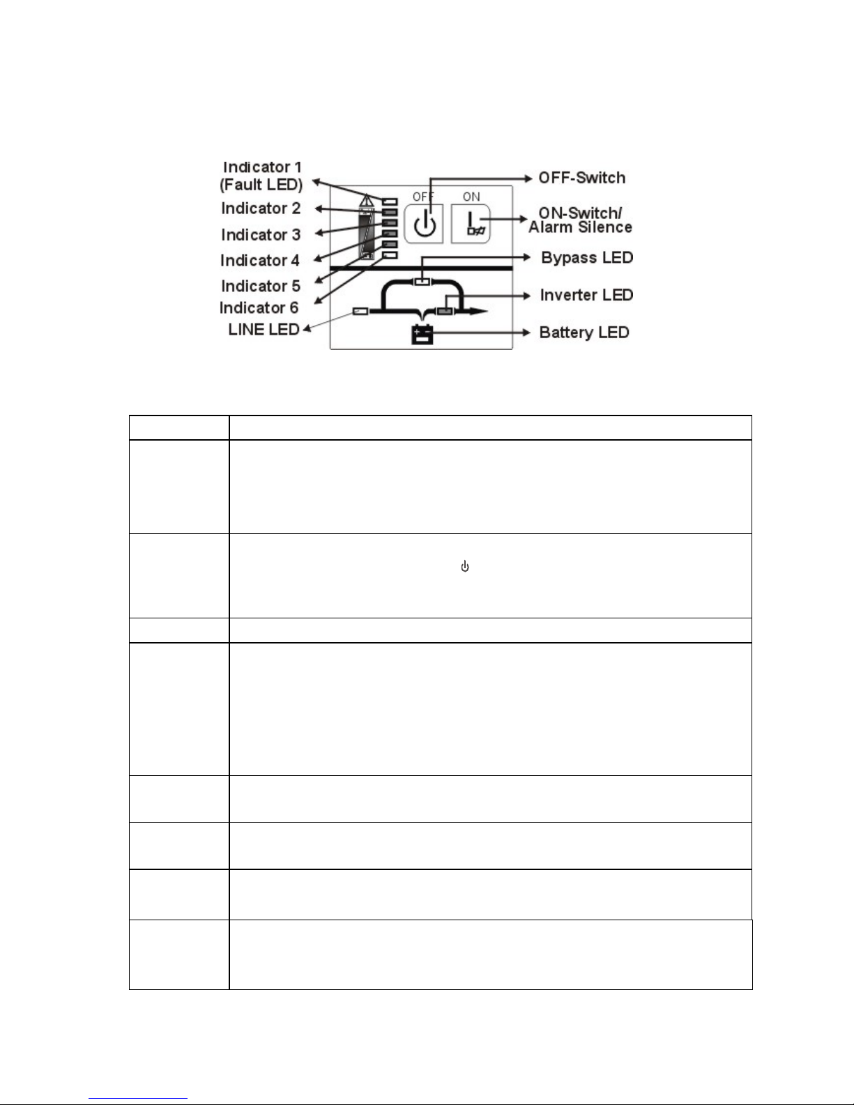
3.1 Display Panel
Figure 1: Display panel
Switch Function
ON - Switch
1. Turn on UPS system:
By pressing the ON-Switch “I“, the UPS system is turned on.
2. Deactivate acoustic alarm:
By pressing this switch, an acoustic alarm can be deactivated.
OFF-Switch
When mains power is normal, the UPS system switches to Standby
mode by pressing OFF-Switch “ “. It is then switched to Bypass and the
inverter is off. At this moment, the output sockets are supplied with
voltage via the bypass if the mains power is available.
Display Function
LINE LED
1. The green LINE LED lights up if mains voltage is applied to the UPS
input.
2. LINE LED blinks when the phase and neutral conductor have been
reversed at the input of the UPS system.
3. If LINE LED and BATTERY-LED light up, the mains power supply is
out of tolerance.
BATTERY
LED
The orange-coloured BATTERY-LED lights up when the mains power
has failed and the inverter is being powered by the batteries.
BYPASS
LED
The orange-coloured BYPASS LED lights up when the UPS system is
supplying voltage provided by the mains power via the bypass.
INVERTER
LED
The green-coloured INVERTER LED lights up if the UPS system is
supplying voltage provided by the mains power via the inverter.
FAULT
LED
The red FAULT LED lights up and an acoustic warning signal is issued
every second when the UPS system is in fault condition. Press the
Standby switch in order to turn off the warning tone.

5
Display Function
Load and
battery
capacity
LED
1. These LEDs show the load of the UPS system if the mains power
is available (normal operation):
2nd LED Over 96% 3rd LED 76%-95%
4th LED 56%-75% 5th LED 36%-55%
6th LED 0-35%.
2. In the battery operation, the LEDs indicate the capacity of the
batteries:
2nd LED 0-25% 3rd LED 26%-50%
4th LED 51%-75% 5th LED 76%-100%
6th LED Over 100%.

6
4. Connection and Operation
The system may be installed and wired only by qualified electricians in accordance with
applicable safety regulations!
When installing the electrical wiring, please note the nominal amperage of your incoming
feeder.
4.1 Inspection
Inspect the packaging carton and its contents for damage. Please inform the transport
agency immediately should you find signs of damage.
Please keep the packaging in a safe place for future use.
NOTE: Please ensure that the incoming feeder is isolated and secured to prevent it from
being switched back on again.
4.2 Connection
4.2.1 UPS Input Connection
If the UPS is connected via the power cord, please use a proper socket with protection
against electric current, and pay attention to the capacity of the socket: over 10A for
1K(S) & 2K, over 16A for 2KS& 3K(S).
4.2.2 UPS Output Connection
The output of 1K(S) and 2KS(Non CE) are socket-types only. Simply plug the load
power cord to the output sockets to complete connection.
Model No.
Output Socket
(pcs)
Terminal Block
1K/1KS 4 Nil
2K 6 Nil
2KS 4(CE) 6(Non CE) Available(CE) Nil (Non CE)
3K/3KS 4(CE) 3(Non CE) Available
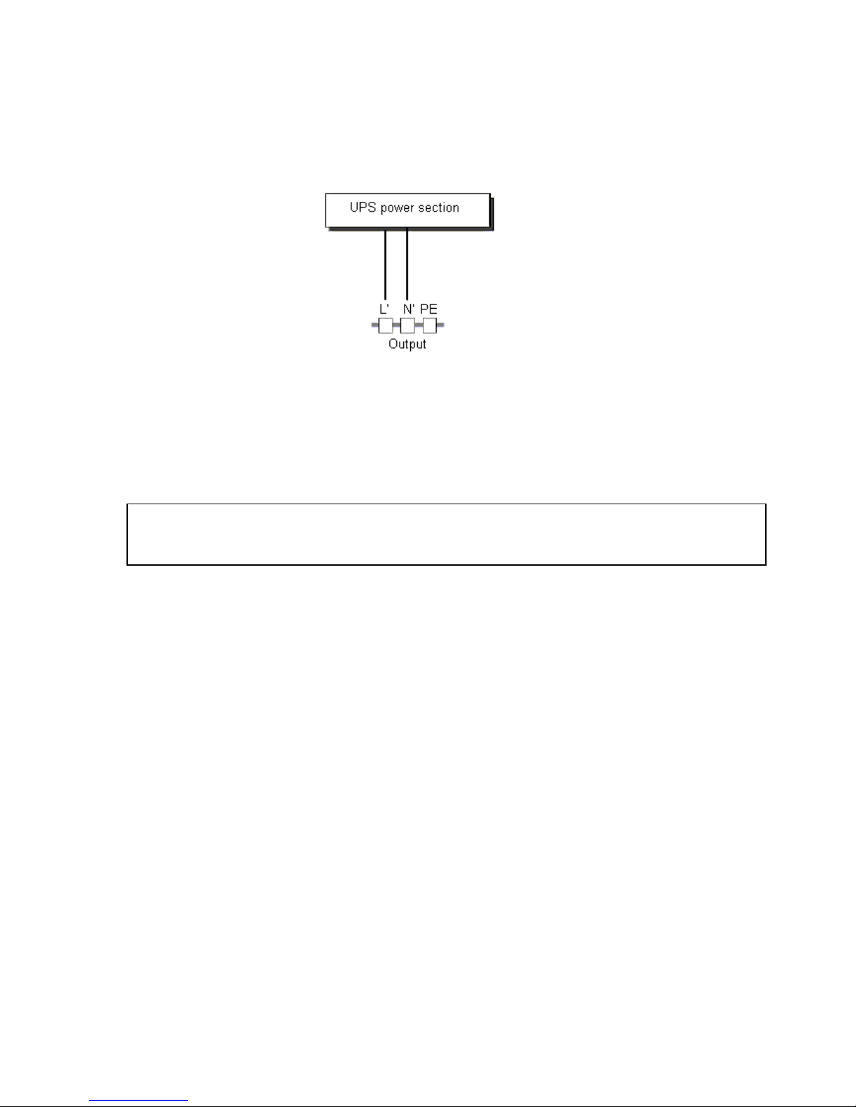
Besides output sockets,2KS(CE) and 3K/3KS has the terminal block available for output
as well.The wiring configuration is shown as the following procedure:
(1) Remove the small cover of the terminal block
(2) Use AWG14 or 2.1mm2 wires for wiring configuration
7
(3) Upon completion of the wiring configuration, please check whether the wires
are securely affixed.
(4) Put the small cover back to the rear panel.
Figure 2: Connection diagram of 2KS(CE) and 3K(S)
4.2.3) Computer Connection:
Connect your computer to the outlet sockets of the UPS system following the above
diagram.
Caution!
The output sockets of the UPS system may still be electrically live even if the power
supply system has been disconnected.
4.3 Battery Charge
Fully charge the batteries of the UPS system by leaving the UPS system connected to the
mains for 1-2 hours. You may use the UPS system directly without charging it but the
stored energy time may be shorter than the nominal value specified.
4.4 Turn On
To turn on the UPS system, press the ON-Switch “I“ on the front panel.
NOTE: The INVERTER-LED lights up after 10 seconds. The BYPASS-LED then goes out
and the ventilation system switches on. The UPS system is now operating correctly.
4.5 Test Function
Test the function of the UPS system by either pressing the On-Switch “I“ or disconnecting
the input of the UPS system from the power supply.
4.6 Operation Procedure of External Battery for Long Backup time Model
(“S” Model)

8
(1) Use the battery pack with voltage: 36VDC for PowerMust 1KS On Line(3 pcs of 12V
batteries). Connection of batteries more than or less than required will cause
abnormality
⑵ One end of the external battery cord is a plug for connecting the UPS and the other
end is a plug for connecting the user battery pack
⑶ Do not connect the UPS to any load yet. Then, connect the power cord of the UPS to
supply utility power to the UPS to make the UPS operation in utility power mode.
⑷ connect one plug of the external battery cord to the user battery pack, then connect
other plug to the external battery socket on the rear panel of the UPS to complete the
connection procedure and the UPS will start to charge the battery pack

9
5. Troubleshooting
If the UPS system does not operate correctly, please attempt to solve the problem using the
table below.
Problem Possible cause Remedy
No indication, no warning
tone even though system is
connected to mains power
supply
No input voltage
Check building wiring socket outlet
and input cable
LINE LED blinks
Phase and neutral
conductor at input of
UPS system are
reversed
Connect UPS system according to
chapter 4 “Connection and
operation”.
LINE-LED blinks and
BATTERY-LED lights up
Input power and/or
frequency are out of
tolerance
Check input power source and
inform dealer if necessary
LINE and BYPASS LED
light up even though the
power supply is available
Inverter not switched
on
Press On-Switch “I”
INVERTER LED lights up,
warning tone at intervals
(every 1 or 4 seconds)
Mains power supply
has failed
It’s in battery operation; warning
tone at intervals of 1 second means
battery is almost empty
FAULT LED lights, warning
tone once a second
Overload Remove loads of UPS output
FAULT-LED lights up,
permanent warning tone
UPS fault Notify dealer!!
Backup time is shorter than
nominal value
Batteries are not fully
charged / batteries
defective
Charge the batteries for at least 1-2
hours and then check capacity. If
the problem still persists, consult
your dealer.
Please have the following information at hand before calling the After-Sales Service
Department:
1. Model number, serial number
2. Date on which the problem occurred
3. Detailed description of the problem

10
6. Maintenance
6.1 Operation
The UPS system contains no user-serviceable parts.
If the battery service life (3 - 5 years at 25 °C ambient temperature) has been exceeded,
the batteries must be exchanged. In this case, please contact your dealer.
6.2 Storage
If the batteries are stored in temperate climatic zones, they should be charged every three
months for 1-2 hours (see Chapter "Connection and Operation"). You should shorten the
charging intervals to two months at locations subject to high temperatures.

11
7. Technical data
7.1 Electrical specifications
INPUT
Model No. 1K(S) 2K 2KS 3K(S)
Phase Single
Frequency (46~54) Hz for 50Hz
Current(A) 7A 9A 12A 16A
OUTPUT
Model No. 1K(S) 2K(S) 3K(S)
Power rating 1kVA/0.7kW 2kVA/1.4kW 3kVA/2.1kW
Voltage 220/230/240×(1 士 2%)VAC
Frequency 50×(1±0.2%)Hz (Battery mode)
Wave form sinusoidal
BATTERIES
Model No. 1K(S) 2K(S) 3K(S)
Number and type
3×12V7Ah 8×12V7Ah 8×12V7Ah
These units bear the CE mark and comply with the following standards:
EN50091-1-1:1996 (safety)
Conducted Emission:EN50091-2..................................................Class B
Radiated Emission: EN50091-2....................................................Class B
Harmonic Current: EN61000-3-2
Voltage Fluctuations and Flicker: EN61000-3-3
EMS: EN61000-4-2(ESD)........................................................Level 4
EN61000-4-3(RS) .........................................................Level 3
EN61000-4-4(EFT).........................................................Level 4
EN61000-4-5(lighting surge)..........................................Level 4
EN61000-2-2 (Immunity to low frequency signals)
7.2 Typical stored energy time (Battery mode)
Typical values at 25°C in minutes:

12
Model No. 100 % Load 50 % Load
1K 5 14
2K 9 21
3K 5 15
7.3 Dimensions and weights
Model No.
Dimensions W x D x H
(mm)
Net Weight
(kg)
1K 145X400X220 14
1KS 145X400X220 7
2K 192X460X340 34.5
2KS 192X460X340 15
3K 192X460X340 35.5
3KS 192X460X340 16
7.4 Communication Port
The type of signals, serial command (RS232), is provided by the POWERMUST ON LINE
SERIES to communicate with a host computer. The RS-232 communication port transmits
both utility power and UPS status to the host computer, providing the host computer with
proprietary command sequence to monitor the utility power and UPS status and to control
the UPS output.
The data format of RS232 is listed as followed:
Baud Rate : 2400 bps
Data Length : 8 bits
Ending Bit : 1 bit
Parity Bit : none
7.4.1 RS232 interface
The following is the pin assignment and
description of DB-9 connector.
Pin # Description I/O
2 TXD Output
3 RXD Input
5 GND Input
9 Wake up
Output
Figure 3: RS232 Interface

13
7.4.2 Free Software Download – WinPower
Free Software Download – WinPower
WinPower is a brand new UPS monitoring software, which provides user-friendly interface
to monitor and control your UPS. This unique software provides safely auto shutdown for
multi-computer systems while power failure. With this software, users can monitor and
control any UPS on the same LAN no matter how far from the UPSs.
Installation procedure:
1. Go to the website: http://www.ups-software-download.com/winpower.htm
2. Choose the operation system you need and follow the instruction described on the
website to download the software.
3. When downloading all required files from the internet, enter the serial No: 511C1-01220-
0100-478DF2A to install the software.
When your computer restarts, the WinPower software will appear as a green plug icon
located in the system tray, near the clock.
7.5 Operating environment
Temperature: 0 °C to 40 °C, Installation height < 1500 m
Relative humidity: 20% to 90 %, no condensation
14
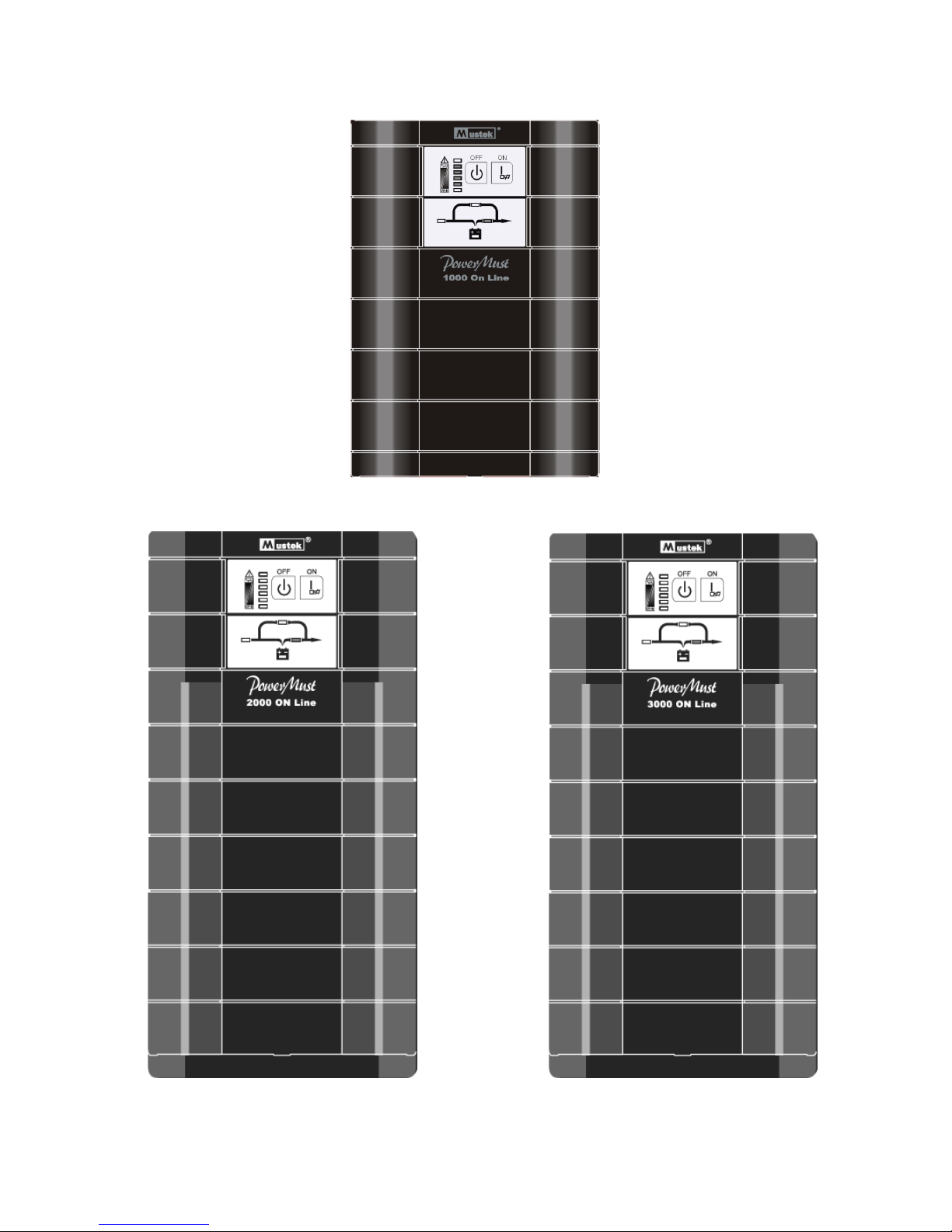
Appendix
Figure 4: Front view of PowerMust 1K/1KS On Line
Figure 6: Front view of
PowerMust 3K/3KS On Line
Figure 5: Front view of
PowerMust 2K/2KS On Line
 Loading...