

MTI MT-900007 User Manual

Installation Instructions for MT-900007
Rev V0, Oct 18th 2004
1. Assemble your electronics inside the MT-900007. If you are using an adapting plate,
assemble the electronics on the adapting plate and install it inside the enclosure.
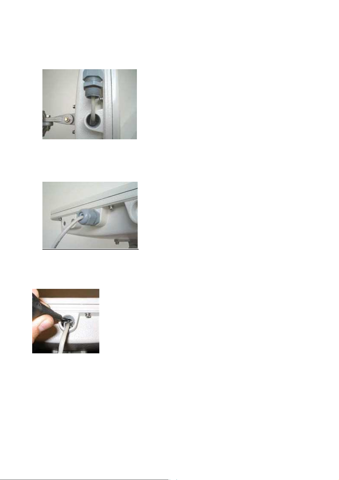
2. Make sure the RJ45 jack is on the side facing the M20 threaded hole as shown in Fig-1.
3. Attach the antenna and the mounting kit to the MT-900007 following the relevant assembly
instructions provided with the MT-900007 and the mounting kit MT-120018/A.
4. Seal the Seal-Test Hole and screw the GND terminal following the relevant assembly
instructions provided with the MT-900007.
Figure 1: View on the M20 Threaded Hole and the RJ45 Jack Inside
5. Insert the CAT5 cable through the M20 water-tight gland provided with the MT-900007 kit
as shown in Fig-2
Figure 2: CAT5 Cable & M20 Water Tight Gland
Installation Instructions for MT-900007
6. Crimp the RJ45 connector to the CAT5 cable and click it into the RJ45 jack as shown in
Fig-3
Figure 3: RJ45 Connected Through M20 Threaded Hole
7. Screw the gland into the M20 threaded hole and tighten as shown in Fig 4. The CPE is ready
for use.
Figure 4: View Showing RJ45 Connected to RJ45 Jack
8. To disconnect the CAT5 cable, open the gland, release, and pull out the RJ45 connector
using a pointed tool such as 00 screwdriver, as shown in Fig-5.
Figure 5: Showing Release and Removal of CAT5 Cable
2
 Loading...