

Page 1
INSTALLATION INSTRUCTIONS
FOR MT-120018/G
RD42255000C/REV-A
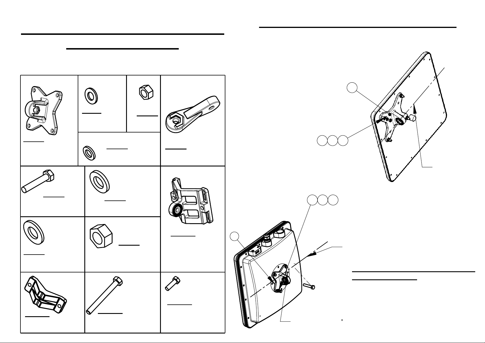
BASE BRACKET INSTALLATION TO ANTENNA
Attach item 1 to the back of the antenna
using items 2,3,4 as shown.
Verify that the oriantation of the hole
in item 1 is alig ned with the elevation axis.
Use tightening torque of 5.7N/m.
1
Item: 1
Antenna/enclosure
base bracket
Qty: 1
Item: 6
Bolt M8x40
Qty: 4
Item: 7
Washer flat M8
Qty: 4
Item: 11
Clamping bracket
Qty: 1
SHEET 1 OF2
Item:2
Flat washer M5
Qty: 4
Item: 3
Spring washer M5
Qty: 4
Item: 8
Washer spring M8
Qty: 4
Item: 12
Bolt M8x70
Qty: 2
Item: 9
Nut M8
Qty: 2
Item: 4
Nut M5
Qty: 4
Item: 5
Arm bracket
Qty: 1
Item: 10
Wall/Poll bracket
Qty: 1
Item: 13
Bolt M5x16
Qty: 4
MT-120018/A only
24
3
x4
x4
x4 x4
2
3
1
x4
ELEVATION
AXIS
x4
13
(MT-120018/A
ONLY)
ELEVATION
AXIS
BASE BRACKET INSTA LLATION
TO ENCLOSURE
Attach item 1 to the back of the enclosure
using items2, 3, 13 as shown.
Verify that the oriantation of the hole
in item 1 is aligned with the elevation axis.
Use tightening torque of 5.7N/m.
For radio in 45
use this set of holes
Page 2
RD41552800C/REV-B
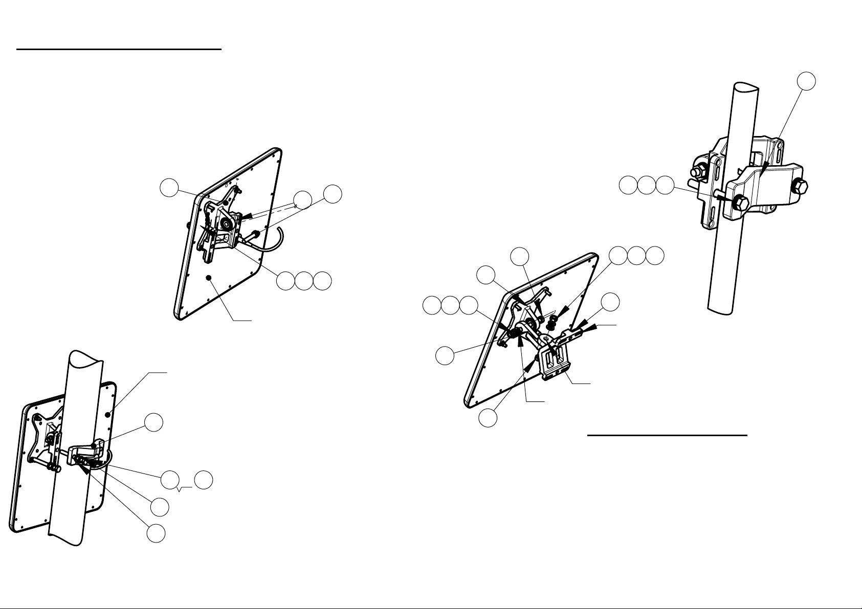
INSTALLATION ON A POLE
Step 1
Connect the base bracket as shown on page 2.
Connect item 10 to item 1 (mate knurled
surfaces) using item 6,7,8,9 as shown.
Note: The bolt head shall be positioned in the
socket on item 1.
Use tightening torque of 24 N/m.
1
ANTENNA OR RADIO
ENCLOSURE
ANTENNA OR
RADIO ENCLOSURE
11
x2
or
6
8
9
SHEET 2 OF 2
12
x2
STEP 2 (FOR POLES SIZES 1.75"-3")
x2
Install the antenna to the pole using item 11,
tighten the bracket using items 8,9,12 (for
small pole diameter use item 6 instead of item 12).
Use tightening torque of 14N/m.
10
7 8 9
STEP 2 (FOR POLES SIZES 1"-1.75")
Install the antenna to the pole using
item 11 as shown, tighten the bracket
using items 8,9,12.
11
Use tightening torque of 14N/m.
6
6
1
987
5
Elevation
6
axis
x2 x2 x2
7 8 9
10
Wall mounting
holes ( Hardware
not supplied)
Azimuth
axis
8912
MOUNTING ON A WALL
Connect base bracket as shown on page 2
Connect item 5 to item 1 (mate the knurled
surfaces) using items 6,7,8,9 as shown.
Note: the bolt head shall be positioned in the
socket of item 1.
mount item 10 on the wall on the desired position.
(note the azimuth axis oriantation)
Attach item 5 to the arm bracket item 10 (mate the
knureld surfaces) using items 6,7,8,9 as
shown. Note the bolt head shall be positioned
in the socket of item 5.
Use tightening torque of 24 N/m to the azimuth
and elevation hardware.
 Loading...