

WIRELESS EDGE
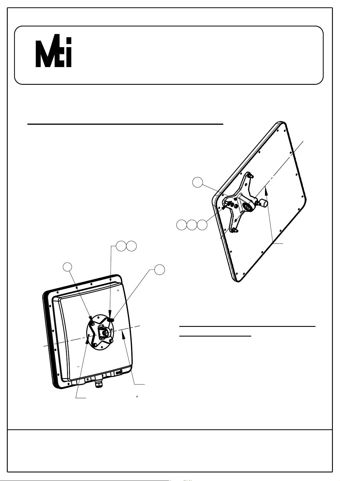
BASE BRACKET INSTALLATION TO ANTENNA
Attach item 1 to the back of the antenna
using items 2,3,4 as shown.
Verify that the oriantation of the hole
in item 1 is alig ned with the elevation axis.
Use tightening torque of 5.7N/m.
1
RD41169400C/REV-G
2
3
4
X4 X4
32
X4
1
13
(MT-120018/A
ONLY)
x4
x4
x4
ELEVATION
AXIS
BASE BRACK ET INSTALLATION
TO ENCLOSURE
Attach item 1 to the back of the enclosure
using items2, 3, 13 as shown.
Verify that the oriantation of the hole
in item 1 is alig ned with the elevation axis.
ELEVATION
AXIS
For radio in 45
use this set of holes
Use tightening torque of 5.7N/m.
SHEET 2 OF 4
11 Hamelacha St. , Afek Industrial Park, Rosh Ha’ayin 48091, Israel
Fax: 972-3-9008901, Tel: 972-3-9008900
www.mtiwe.com
WIRELESS EDGE
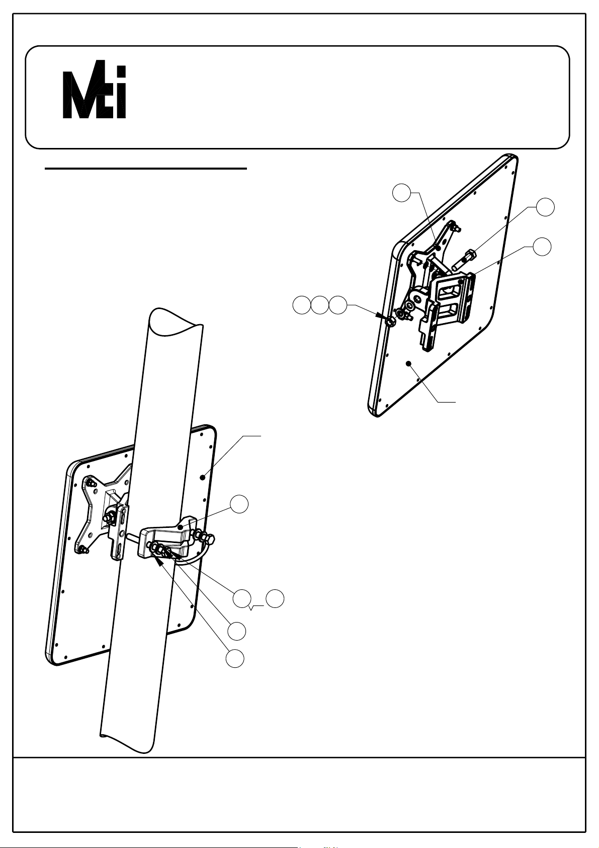
INSTALLATION ON A POLE
Step 1
Connect the base bracket as shown on page 2.
Connect item 10 to item 1 (mate knurled
surfaces) using item 6,7,8,9 as shown.
Note: The bolt head shall be positioned in the
socket on item 1.
Use tightening torque of 24 N/m.
8 7
9
RD41169400C/REV-G
1
6
10
11
8
9
ANTENNA OR
RADIO ENCLOSURE
STEP 2 (FOR POLES SIZES 1.75"-3")
Install the antenna to the pole using item 11,
tighten the bracket using items 8,9,12 (for
small pole diameter use item 6 instead of item 12).
Use tightening torque of maximum14N/m.
x2
6
or
Alternately and equally tighten the two M8 bolts
up to it's defined tightening torque ,
12
in order to prevent unequal pressure
on the cast Clamps
x2
x2
ANTENNA OR RADIO
ENCLOSURE
SHEET 3 OF 4
11 Hamelacha St. , Afek Industrial Park, Rosh Ha’ayin 48091, Israel
Fax: 972-3-90 089 01, Tel: 972-3-9008900
www.mtiwe.com

WIRELESS EDGE
STEP 2 (FOR POLES SIZES 1"-1.75")
Install the antenna to the pole using
item 11 as shown, tighten the bracket
using items 8,9,12.
Use tightening torque of maximum14N/m.
Alternately and equally tighten the two M8 bolts
up to it's defined tightening torque ,
in order to prevent unequal pressure
on the cast Clamps
x2 x2
RD41169400C/REV-G
11
x2
8912
1
987
5
SHEET 4 OF 4
6
7 8 9
10
Wall mounting
holes ( Hardware
not supplied)
Azimuth
axis
6
Elevation
axis
MOUNTING O N A WALL
Connect base bracket as shown on page 2
Connect item 5 to item 1 (mate the knurled
surfaces) using items 6,7,8,9 as shown.
Note: the bolt head shall be positioned in the
socket of item 1.
mount item 10 on the wall on the desired position.
(note the azimuth axis oriantation)
Attach item 5 to the arm bracket item 10 (mate the
knureld surfaces) using items 6,7,8,9 as
shown. Note the bolt head sh all be positioned
in the socket of item 5.
Use tig htening torque of 24 N/m to the azimuth
and elevation hardware.
11 Hamelacha St. , Afek Industrial Park, Rosh Ha’ayin 48091, Israel
Fax: 972-3-9008901, Tel: 972-3-9008900
www.mtiwe.com

RD41169400C/REV-G
WIRELESS EDGE
INSTALLATION INSTRUCTIONS
FOR
MT-120018 AND MT-12001 8/A
Item: 4
Item: 1
Antenna/enclosure
base bracket
Qty: 1
Item: 7
Washer flat M8
Qty: 4
Item: 6
Bolt M8x40
Qty: 4
Item:2
Flat washer M5
Qty: 4
Item: 3
Spring washer M5
Qty: 4
Nut M5
Qty: 4
Item: 8
Washer spring M8
Qty: 4
Item: 9
Nut M8
Qty: 2
Item: 5
Arm bracket
Qty: 1
Item: 10
Wall/Poll bracket
Qty: 1
Item: 11
Clamping bracket
Qty: 1
SHEET 1 OF 4
Item: 12
Bolt M8x70
Qty: 2
Item: 13
Bolt M5x16
Qty: 4
MT-120018/A only
11 Hamelacha St. , Afek Industrial Park, Rosh Ha’ayin 48091, Israel
Fax: 972-3-9008901, Tel: 972-3-90089 00
www.mtiwe.com
 Loading...