

Page 1
❒ Wrenches (two 9/16 inch)
❒ Screwdriver (medium-sized)
❒ Soft Rubber Mallet
❒ Penetrating Oil
❒ Metal File (needed only if
tine holders are also
removed)
How To Reach Us
If you have any questions about removing or installing tines, please
refer to the “Customer Assistance” information on the back cover.
These instructions apply only
to owners of the following
tillers:
❒ HORSETMModel
❒ ECONO HORSE
TM
Model
❒ PONY
®
Model
First, read the general
information given for all model
tillers on Pages 1 through 4. You
will then be directed to installation instructions for your
particular model tiller. Carefully
look at the adjacent figures while
following the step-by-step
instructions. Finally, see the
Bolo Tines Maintenance Section
on Page 16.
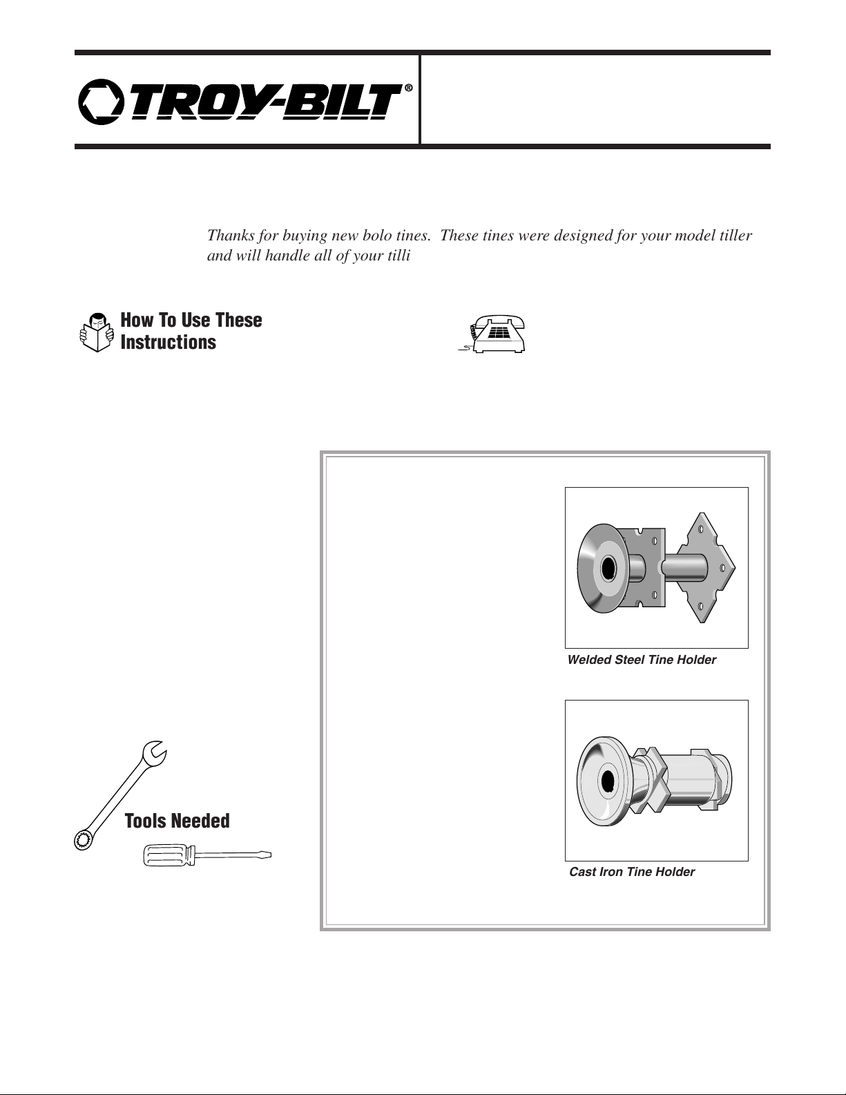
Attention!
HORSE Model Owners
Horse Model tillers have two
different style tine holders as
shown in figures to the right:
❒ Welded steel
Note: Welded steel holders may
be secured to tine shaft either
with two bolts and nuts or with
single mounting bolt (illustrated
in these instructions).
❒ Cast iron
Owners of HORSE Model
tillers with
cast iron tine holders
should keep the cardboard box in
which this kit was shipped to use
with the template (pattern) on the
inside back cover of these
instructions. You will use both
the template and the box when
assembling tines.
Owners of all other models can
ignore the template and discard
the box.
Welded Steel Tine Holder
Cast Iron Tine Holder
How To Use These
Instructions
Tools Needed
Thanks for buying new bolo tines. These tines were designed for your model tiller
and will handle all of your tilling needs including sod busting, seedbed preparation,
cultivating, and turning under crop residue.
THANK
YOU!
Bolo Tine Kit
OEM-290-253 / 290-253-081
for HORSETM, ECONO HORSETM,and PONY®Tillers
Installation Instructions
Page 2

C. Use two 9/16-inch wrenches
to remove the bolts which attach
the tines to the holders. (Tines
are not attached to cast iron
holders with bolts. In the case
of cast iron holders, remove
each gang [set of four tines]
from a holder by removing
only one bolt, and then
loosening the other three bolts
on the same gang.)
D. Always discard old hardware
and tines. Use only the
hardware which came with your
new tines.
Bolt Removal Tips
❑ Loosen all four nuts on a holder plate or tine gang before trying to remove any of the nuts and bolts.
❑ If necessary, use penetrating oil to loosen stubborn nuts.
❑ If necessary, place the closed (boxed) end of a wrench on the nut and sharply tap the wrench with the
rubber mallet until the nut is loose.
Item Qty Part # Description
Horse, Econo Horse, 8 GW-1270-1 Left-curved Tines
and Pony Standard Tines 8 GW-1270-2 Right-curved Tines
Hardware for Standard 16 1100043 3/8"-16 x 1-1/4" Hex Head Bolts (Grade 5)
Tines (All Models) 16 1733398 3/8"-16 Hex Locknuts
Custom Tines 8 GW-2475-1 Left-curved Custom Tines
(All Models) 8 GW-2475-2 Right-curved Custom Tines
16 710-0514 3/8"-16 x 1-1/4" Hex Head Bolts (Grade 5)
16 712-0798 3/8"-16 Hex Nuts
16 736-0169 3/8" Lock Washers
If You Ordered Custom
Tines...
Custom tines (special, hardfaced tines which last up to 21/2 times longer than standard tines) are perfect for
tilling sandy, gritty soil, or for
custom tilling or market gardening.
If you received Custom
tines, read this General
Information and then follow
the standard tine installation
instructions which apply to
your particular model tiller.
If you have any difficulty
installing your Custom tines,
contact our Service
Department (Refer to the
back cover of this manual.)
2
Step 1: Check Your Parts
Remove the tines and hardware package and check that you received all of the parts listed below for your
model tiller. If any parts are missing or damaged, contact our Technical Service Department and we will arrange
for replacements.
To prevent serious personal
injury when removing or
installing your bolo tines:
• Stop the engine, and
remove the electric start
key (if your tiller features
electric start).
• Let the engine and
muffler area cool.
• Disconnect the spark
plug wire, and position the
wire away from the plug to
prevent accidental starting.
WARNING
Tine edges can be sharp
and can have slivers that
could cause personal
injury. Use care at all
times when handling tines.
The tine hood edges may
also be sharp. To prevent
personal injury, wear thick
gloves when touching the
edges of the hood.
CAUTION
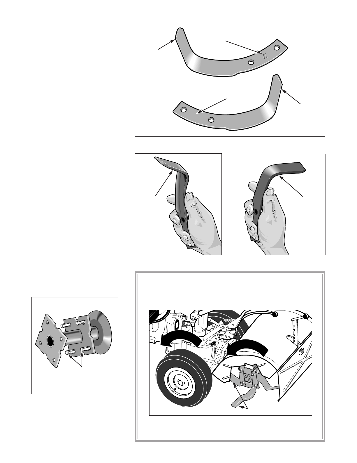
Step 2: Tine Removal
A. Carefully tilt the tiller
forward until the engine is
resting on the ground. (On some
models it may be necessary to
prop up the rear of the tiller or to
add additional weight to the
engine to stabilize the tiller in
this position.)
B. Raise the tiller hood flap and
secure it out of the way with a
rubber band, string or, in the case
of the PONY tiller, with the
depth regulator adjustment bar
knob.
PRE-INSTALLATION STEPS
Page 3
3
Step 3: Tine Identification
Separate the sixteen new tines
into two groups: eight left-
curved tines and eight rightcurved tines. Tines can be
identified as either left-curved or
right-curved tines in two ways:
Figure 1: Look for "L" or "R" stamped on the tines.
Figure 4: Insertion of bolts.
Step 4: Bolt Installation
NOTE: Skip this step if you
have a HORSE Model tiller with
cast iron tine holders.
A. On all other models, place
the sixteen bolts through the
holes in the tine holders with the
threaded ends of the bolts
pointing outward toward each
side of the tiller as shown below
in Figure 4.
(The installation of
tines on holders is described
later in these instructions.)
Figure 3: Right-curved tine.
Figure 2: Left-curved tine.
B. Or, hold the tine with the
blunt edge toward you. If the tip
curves toward the left, the tine is
a left-curved tine. If the
tip
curves toward the right, the tine
is a right-curved tine. See
Figures 2 and 3 which show the
two types of tines.
A. The letters and numbers
stamped on the side of each tine
are factory code marks which
contain either an "L" (on leftcurved tines) or an "R" (on rightcurved tines). See Figure 1.
Blunt
Edge
Blunt
Edge
B. Sort lock washers and nuts
into four groups of four each.
Figure 5: Cutting edges of tines must enter the soil first when the
tiller moves forward.
I
MPORTANT: Tines rotate in the same direction as the
wheels. During the installation steps, place tines on holders
so cutting edges (not the blunt, wider edges) will enter the soil
first when the tiller moves forward. See Figure 5.
Threaded
Ends
Cutting Edges
Tip Pointing
Up
Tip Pointing
Up
Look for "L" on
Left-curved Tine
Look for "R" on
Right-curved Tine
70
70
ER
ER
R
l
o
e
t
e
a
W
h
t
i
o
n
R
o
e
t
n
i
a
T
t
i
o
n
Page 4
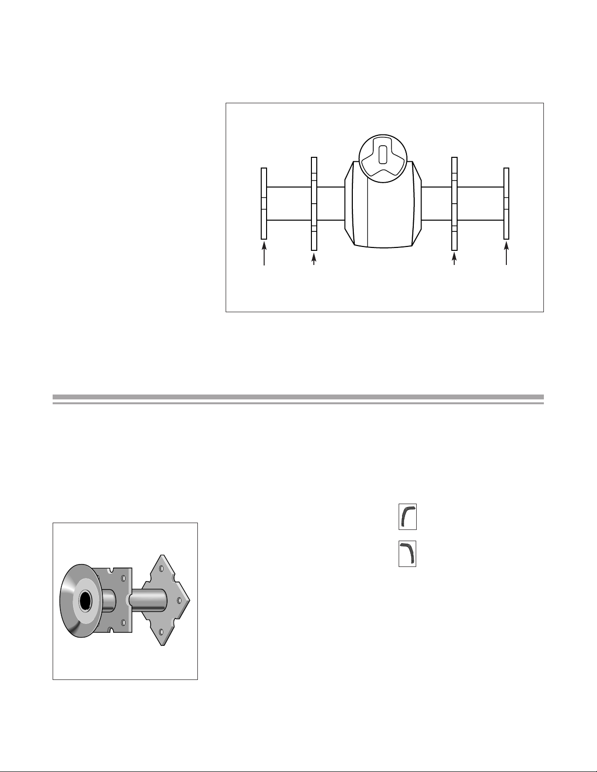
Use this procedure to install
tines only if your tine holders are
shaped as shown below in
Figure 7.
NOTE: Be sure to use the
specific tines (left or right
curved) called for in each
installation step.
HORSE MODEL TINE INSTALLATION
(WELDED STEEL HOLDERS)
Figure 7: Welded steel tine holder.
Step 1: Position Holders
Before Starting Tine
Installation
On PTO Models, disengage the
PTO Lever. On non-PTO
Models, place the Forward/
Reverse Lever in Neutral.
Rotate the tine holders and
shaft (by hand) until any one of
the semi-circles on the
outer
mounting plates of the holders is
at the 12 o'clock position in
relation to the ground. See
Figure 8 on Page 5.
Step 2: Install Tines on Left
Inner Holder
Tines used in this step:
two right-curved tines
followed by
two
left-curved tines
A. Place two right-curved tines
(shown shaded in Figure 8)
opposite each other on the
previously installed bolts. Make
sure that the tines are positioned
as follows:
✔ Tines are across from each
other.
✔ Tines are against the outer
surface of the left inner holder
plate.
NOTE: When installing the
tines you will be directed to
perform a two step procedure
and then check to ensure that the
installation is correct before
going on to the next step.
4
Step 5: Find the Installation Instructions for Your Model
Each tiller's distinctive tine pattern provides the optimum in tilling performance for that model. Be sure to
install tines in the pattern described for your tiller.
Find your tiller in the following list and go to the indicated
page to continue with tine installation.
❑ HORSE (Welded Steel Tine
Holders), see the instructions
at the bottom of this page.
❑ HORSE (Cast Iron Tine
Holders), see
Page 8.
❑
PONY, see Page 12.
❑ ECONO HORSE, see Page 14.
Figure 6: Order of installation on holders (welded steel holders shown).
On all models, tines will be
installed in the following order
(see Figure 6):
A Left Inner Holder
B. Right Inner Holder
C. Left Outer Holder
D. Right Outer Holder
Order of Installation
C A B D
Page 5
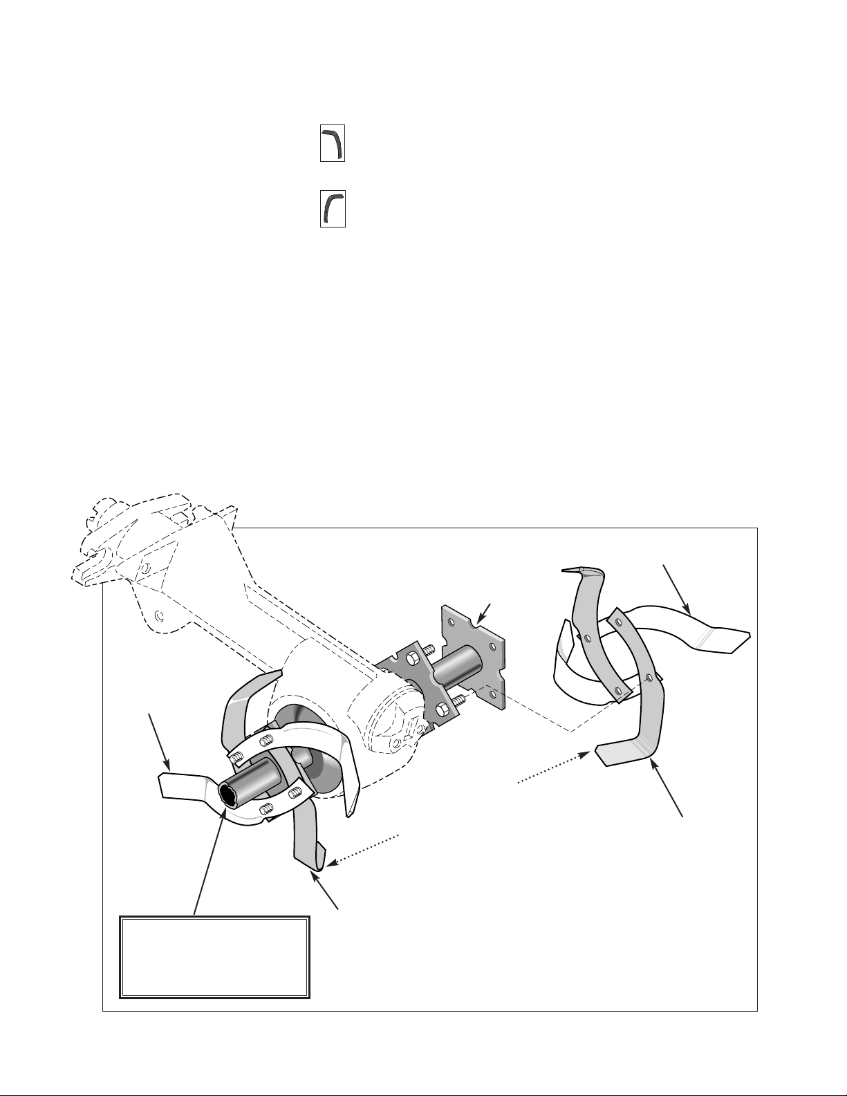
Step 3: Install Tines on Right
Inner Holder
Tines used in this step:
two left-curved tines
followed by
two right-curved tines
A. Place two left-curved tines
(shown shaded in Figure 8)
opposite each other on the
previously installed bolts. Make
sure that the tines are positioned
as follows:
✔ The tips of these two tines
should be directly opposite the
tips of the two right-curved tines
installed on the left inner holder
in Step 2-A (see Figure 8).
5
✔ Tips point inward toward
the transmission housing.
✔ The cutting edges will enter
the soil first when the tiller
moves forward.
B. Place two left-curved tines
(unshaded in Figure 8) opposite
each other on the bolts, overlapping the tines installed in Step
2-A. Make sure that the tines are
positioned as follows:
✔ These tines are also across
from each other.
✔ Tips point outward toward
the sides of the tiller.
✔ The cutting edges will enter
the soil first when the tiller
moves forward.
C. Add lock washers and nuts to
all four bolts and tighten
securely.
Figure 8: Installing tines on inner holders.
✔ Tines are against the outer
surface of the right inner holder
plate.
✔ Tips point inward toward
the transmission housing.
✔ The cutting edges will enter
the soil first when the tiller
moves forward.
B. Place two right-curved tines
(unshaded in Figure 8) opposite
each other on the bolts, overlapping the tines installed in Step
3-A. Make sure that the tines are
positioned as follows:
✔ These tines are also across
from each other.
✔ Tips point outward toward
the sides of the tiller.
✔ The cutting edges will enter
the soil first when the tiller
moves forward.
C. Add lock washers and nuts to
all four bolts and tighten
securely.
Right-curved
Tine
Left -curved
Tine
Left-curved
Tine
Right-curved
Tine
To allow an unobstructed view
of the left inner tine holder,
the left outer tine holder is not
shown in this drawing.
Position SemiCircle at 12
o'clock
Tips of innermost tines
are directly opposite
from and point toward
each other.
Page 6
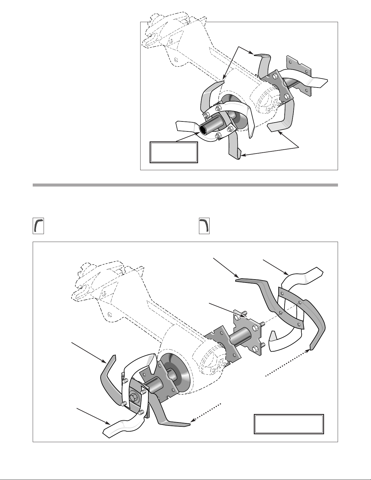
Figure 9: Innermost tines on inner holders.
Step 5: Install Tines on Left Outer Holder
Tines used in this step:
Two right-curved tines followed two left-curved tines
Figure 10: Installing tines on outer holders.
6
Step 4: Check the Installation
This completes the installation
of the tines on the two inner
holders. To ensure that the
installation is correct, check for
the following:
A. Make sure that the tips of the
four innermost tines (those
nearest the transmission
housing) are directly opposite
each other, pointing toward each
other and toward the transmission housing. See Figure 9.
B. Make sure that the cutting
edges of all tines will enter the
soil first when the tiller moves
forward.
Left-curved
Tine
Right-curved
Tine
Left-curved
Tine
Right-curved
Tine
Innermost
Tines
Position SemiCircle at 12 o'clock
Tips of innermost tines
are directly opposite from
and point toward each
other.
Innermost
Tines
Left outer holder
not shown.
Tines on inner holders
not shown.
Page 7

7
✔ Tips point inward toward
the transmission housing.
✔ The cutting edges will enter
the soil first when the tiller
moves forward.
B. Place two left-curved tines
(unshaded in Figure 10) opposite
each other on the bolts,
overlapping the tines installed in
Step 5-A. Make sure that the
tines are positioned as follows:
✔ Tines are across from each
other.
✔ Tips point outward toward
the sides of the tiller.
✔ The cutting edges will enter
the soil first when the tiller
moves forward.
C. Add lock washers and nuts to
all four bolts and tighten
securely
A. Place two right-curved tines
(shown shaded in Figure 10)
opposite each other on the
previously installed bolts. Make
sure that the tines are positioned
as follows:
✔ Tines are across from each
other.
✔ Tines are against the outer
surface of the left holder outer
plate.
Step 6: Install Tines on Right
Outer Holder
Tines used in this step:
two left-curved tines
followed by
two right-curved tines
A. Place two left-curved tines
(shown shaded in Figure 10)
opposite each other on the
previously installed bolts. Make
sure that the tines are positioned
as follows:
✔ The tips of these tines are
directly opposite the tips of the
two tines installed in Step 5-A.
✔ Tines are against the outer
surface of the right holder outer
plate.
✔ Tips point inward toward
the transmission housing.
✔ The cutting edges will enter
the soil first when the tiller
moves forward.
B. Place two right-curved tines
(shown unshaded in Figure 10)
opposite each other on the bolts,
overlapping the tines positioned
in Step 6-A. Make sure that the
tines are positioned as follows:
✔ Tines are across from each
other.
✔ Tips point outward toward
the sides of the tiller.
✔ The cutting edges will enter
the soil when the tiller moves
forward.
C. Add lock washers and nuts to
all four bolts and tighten
securely
Step 7: Check the Installation
This completes the installation
of the tines on the two outer
holders. To ensure that the
installation is correct, check for
the following:
A. Make sure that the tips of the
four innermost tines on the
outer holder (those nearest the
transmission) are directly
opposite each other and pointing
inward, toward each other. See
Figure 11.
This completes the installation
steps for HORSE Models with
welded steel tine holders. Also
read and follow the instructions
given in the Bolo Tines Maintenance Section on Page 16.
B. Make sure that the cutting
edges of all tines will enter the
soil first when the tiller is
moving forward.
Figure 11: Outermost tines on outer holders.
Innermost
Tines
Innermost Tines
Page 8

8
HORSE MODEL TINE ASSEMBLY AND INSTALLATION
(CAST IRON HOLDERS)
Use these instructions only if
your tiller is equipped with tine
holders shaped as shown below
in Figure 12.
Figure 12: Cast iron tine holder.
;;
@@
ÀÀ
;;
@@
ÀÀ
;;
@@
ÀÀ
;
;
;
;;
@
@
@
@@
À
À
À
ÀÀ
;
;
;
;;
@
@
@
@@
À
À
À
ÀÀ
;
;
;
;;
@
@
@
@@
À
À
À
ÀÀ
Figure 13: Template taped on box.
Figure 14: Three "A" gangs and one "B" gang.
Step 1: Assemble Tines Into
Gangs
Before starting this procedure,
tape the tine pattern template
(from the inside back cover),
onto the bottom of the shipping
box as shown in Figure 13.
Position the box with the taped
template in front of you.
In this assembly procedure,
you will be assembling leftcurved and right-curved tines
into gangs (sets of four tines
assembled according to a
specific pattern). When the
assembly is complete, you will
have three (3) "A" gangs and one
(1) "B" gang (see Figure 14).
All "A" gangs have have an
identical tine pattern. The "B"
gang has a slightly different
pattern.
A A A
B
#3
#3 TINE
UP
POINTS
E
L
or
A
#4 TINE
POINTS
or
BOLT
A
L
E
R
or
A
R
BOLT
#2
POINTS
DOWN
TINE
E
L
L
UP
#1
POINTS
DOWN
BOLT
TINE
E
R
or
A
R
#4
Page 9

9
A. Place two left-curved tines
onto the template so that the
tines cover the outlines of tines
#1 and #2 as shown in Figure 15.
The tips of the tines point
Figure 15: Assembly of an "A" gang. Figure 16: Insert bolts.
Step 3. Assemble One "B" Gang
Tines used in this step:
two right-curved tines
followed by
two left-curved tines
downward (overhanging the
sides of the box).
B. Place three bolts through the
holes as shown in Figure 16.
C. Place two right-curved tines
(shown in Figure 16) onto the
bolts so that the tines cover the
outlines of tines #3 and #4.
These tines are opposite each
other on top of the tines already
in place. The tips of these tines
face upward as shown.
NOTE: Do not insert a bolt
through the fourth hole.
D. Add lockwashers (not used
with Custom tines) and nuts to
the three bolts and barely tighten
the nuts (just so they do not fall
off the bolts).
E. For future identification
when installing the gangs on the
holders, use chalk or crayon to
mark each gang with an "A."
F. Repeat Steps A through E to
construct two more "A" gangs.
Set these gangs aside until you
install them in Step 4 on
Page 10.
A. Position the box (with the
attached template) in front of
you as was done when
assembling the "A" gangs.
B. Place two right-curved tines
(shown in Figure 17 on Page 10)
onto the template so that the
tines cover outlines of tines #3
and #4. The tips of these tines
point upward.
C. Place three bolts through the
holes shown in Figure 18 on
Page 10.
D. Place two left-curved tines
(shown in Figure 18) onto the
bolts so that the tines cover the
outlines of tines #1 and #2.
These tines are opposite each
other on top of the tines already
in place. The tips of these tines
point downward (overhanging
the sides of the box).
two left-curved tines
followed by
two right-curved tines
Step 2: Assemble Three "A"
Gangs
Tines used in this step:
;;
@@
ÀÀ
;;
@@
ÀÀ
;;
@@
ÀÀ
;;;
;;;
@@@
@@@
ÀÀÀ
ÀÀÀ
;;;
;;;
@@@
@@@
ÀÀÀ
ÀÀÀ
;;;
;;;
@@@
@@@
ÀÀÀ
ÀÀÀ
;@À;@À;@
À
;;
;
;
;
@@
@
@
@
ÀÀ
À
À
À
;;
;
;
;
@@
@
@
@
ÀÀ
À
À
À
;;
;
;
;
@@
@
@
@
ÀÀ
À
À
À
Cutting
Edge
Cutting
Edge
Cutting
Edge
Cutting
Edge
#3
#3 TINE
UP
#1
POINTS
DOWN
TINE
#4
POINTS
E
L
or
BOLT
E
R
or
A
R
E
L
or
A
L
#4 TINE
POINTS
UP
BOLT
A
L
E
R
or
A
R
#2
TINE
BOLT
POINTS
DOWN
#1
TINE
POINTS
DOWN
E
or
A
R
#4
#3
#3 TINE
UP
POINTS
E
L
or
BOLT
R
E
L
or
A
L
#4 TINE
POINTS
UP
BOLT
A
L
E
R
or
A
R
#2
TINE
BOLT
POINTS
DOWN
Page 10

C. Insert a new bolt (of the four
set aside for this set) through the
remaining set of holes in the
tines. (See "Installation Tips" on
Page 11.) Add lockwashers (not
used with Custom tines) and
nuts. Tighten all four bolts
securely.
;@À;@À;@
À
;
;
;
;
@
@
@
@
À
À
À
À
;
;
;
;
@
@
@
@
À
À
À
À
;
;
;
;
@
@
@
@
À
À
À
À
10
;;@@ÀÀ;;@@ÀÀ;;@@À
À
;
;
;
;
@
@
@
@
À
À
À
À
;
;
;
;
@
@
@
@
À
À
À
À
;
;
;
;
@
@
@
@
À
À
À
À
Figure 18: Add lockwashers and nuts to "B" gang.
Figure 19: Position of tine gangs on cast iron holders as viewed from rear
of tiller.
E. Add locknuts to the three
bolts and barely tighten the nuts
(just so they do not fall off the
bolts).
F. For future identification when
installing this gang on the
holder, use chalk or crayon to
mark the gang with a "B."
B. Rotate the gang so that the
the two innermost tines are
around one lug on the tine holder
and the other two tines are
around the other lug.
In the gangs just assembled, all
cutting edges are facing in one
direction. When installed on the
holders, these cutting edges must
enter the soil first when the tiller
is moving forward. Figure 19
shows the correct position on the
tine holders for the three "A"
gangs and the "B" gang.
Note that each holder shows a
letter which corresponds to the
"A" and "B" markings on the
tine gangs just assembled, and a
number which represents the
order in which the tine gangs are
installed on the holders.
A. Make sure that the tine bolts
are loose. Take one "A" gang
and wrap it around the tine
holder at position #1. Check that
the cutting edges are positioned
so that they will enter the soil
first when the tiller moves
forward.
Figure 17: Assembly of a "B" gang.
NOTE: Do not insert a bolt
through the fourth hole.
Step 4: Install Gangs on Holders
B
3
A
A A
421
Cutting
Edge
Cutting
Edge
Cutting
Edge
Cutting
Edge
#3
#3 TINE
UP
POINTS
E
L
#1
TINE
POINTS
DOWN
or
A
#4
or
BOLT
A
E
R
L
R
E
L
BOLT
or
A
L
#4 TINE
POINTS
UP
#3
#4
#3 TINE
UP
POINTS
E
L
or
BOLT
E
R
or
A
R
E
L
or
A
L
#4 TINE
POINTS
UP
BOLT
A
L
E
R
or
A
R
#2
TINE
BOLT
POINTS
DOWN
BOLT
E
R
or
A
R
#2
TINE
POINTS
DOWN
#1
POINTS
DOWN
TINE
Page 11

11
D. Follow the procedure
described in Steps A through C
to install the other two "A"
gangs at positions #2 and #4.
E. Install the "B" gang on the
left outer holder at position #3 as
shown in Figure 20, after
following Steps A through C
above.
Step 5: Check the Installation
This completes the installation of the tines. To ensure that the installation is correct, check for the following:
❑ Make sure that the tips of the four innermost tines (on the left and right sides) are directly opposite each
other and pointing toward each other. See Figure 20.
❑ Make sure that the cutting edges of all tines will enter the soil first when the tiller is moving forward.
❑ Also read and follow the instructions provided in the Bolo Tines Maintenance Section on Page 16.
Figure 20: Tines installed on cast iron holders.
Installation Tips
If you encounter difficulty in aligning the two holes when
inserting the fourth bolt, check the following:
❑ Make sure that the bolts in the other three sets of holes are as
loose as possible.
❑ Use a screwdriver inserted through the two empty holes to pry
the tines together.
❑ Use a mallet to lightly tap the tines into the proper position.
❑ If the holes still cannot be aligned, remove the tine gangs from
the holder, remove the holder from the tine shaft and examine
the holder for rough spots in the groove between the lugs.
Smooth any rough spots with a metal file and repeat Steps A
through C. Refer to your Owner/Operator Manual for holder
removal and replacement instructions.
A Gang
A Gang
A Gang
B Gang
Innermost
Tines
Page 12

PONY MODEL BOLO TINE INSTALLATION
12
Follow these installation steps
if you own a PONY Tiller.
ECONO HORSE owners
follow only Steps 1 and 2
below.
Step 1: Install Tines on Left
Inner Holder
Tines used in this step:
four right-curved tines
A. Begin installing new tines on
the left inner holder. See
Figure 21.
B. Carefully place two right-
curved tines (shown shaded in
Figure 21) opposite each other
on the previously installed bolts.
Make sure that tines are positioned as follows:
✔ Tines are across from each
other.
✔ Tines are against the outer
surface of the left holder inner
plate.
✔ The tips point inward
toward the transmission housing.
✔ The cutting edges will enter
the soil first when the tiller
moves forward.
C. Place two more right-curved
tines (shown partially shaded in
Figure 21) opposite each other
on the bolts, overlapping the
tines installed above in Step 1-B.
Make sure that the tines are
positioned as follows:
✔ Tines are across from each
other.
✔ The tips point inward
toward the transmission housing.
✔ The cutting edges will enter
the soil first when the tiller
moves forward.
D. Add lock washers and nuts to
all four bolts and tighten
securely.
Step 2: Install Tines on Right
Inner Holder
Tines used in this step:
four left-curved tines
ECONO HORSE owners should now go to the instructions for
the Left Outer Holder on Page 14 to complete tine installation.
Figure 21: Installing tines on left inner tine holder.
Figure 22: Installing tines on right inner tine holder.
in Step 1 for the left inner holder.
(The tips of the first two tines
installed in this step should be
directly opposite and point
toward the tips of the first two
tines installed in Step 1-B.)
Make sure that the tips of all
tines point inward, and that all
cutting edges face forward.
Right-curved
Tines
Right-curved
Tines
Left-curved
Tine
Install the four left-curved
tines on the outer surface of the
right inner holder (see Figure
22) using the procedure given
NOTE: To allow an
unobstructed view of the left
inner holder, the left outer
holder is not shown.
Page 13

Step 3. Install Tines on Left
Outer Holder
Tines used in this step:
four right-curved tines
Follow Steps 1-A through 1-D
on Page 12 to install right-
curved tines on the left outer
holder. Make sure that the tines
are installed against the outer
surface of the holder. Make sure
that all tips point inward, and all
cutting edges face forward. See
Figure 23.
Step 4: Install Tines on Right
Outer Holder
Tines used in this step:
four left-curved tines
Follow Step 2 on Page 12 to
install left-curved tines on the
right outer holder. Make sure
that the tines are installed against
the outer surface of the holder.
All tips point inward. See Figure
23 which shows PONY tines
completely installed.
Step 5: Check the Installation
This completes the installation
of the tines on your PONY
Tiller. To ensure that the
installation is correct, check for
the following:
❑ Make sure that the tips of all
tines are pointing inward
(toward the transmission
housing).
❑ Make sure that the cutting
edges of all tines will enter
the soil first when the
tiller is moving forward.
Also read and follow the
instructions provided in the Bolo
Tines Maintenance Section on
Page 16.
13
Figure 23: PONY tines installed.
Eight Rightcurved Tines
Eight Leftcurved Tines
NOTE: Shaded tines
are installed first.
Innermost Tines
Innermost Tines
Page 14

ECONO HORSE MODEL BOLO TINE INSTALLATION
Follow these installation steps only if you own an ECONO HORSE Tiller.
NOTE: Tines on inner holders
are installed the same for both
PONY and ECONO HORSE
Tillers. However, tines on the
outer holders of the ECONO
HORSE have a different
installation pattern as explained
in the following instructions.
ECONO HORSE Tiller owners should first follow Steps 1
and 2 of the instructions given on Page 12 for installing
tines on the PONY Model. Then, return to Step 1 below to
continue tine installation on your ECONO HORSE Model.
Step 1: Install Tines on Left
Outer Holder
Tines used in this step:
two right-curved tines
followed by
two left-curved tines
A. Place two right-curved tines
(shown shaded in Figure 24)
opposite each other on the
previously installed bolts. Make
sure that the tines are positioned
as follows:
✔ Tines are across from each
other.
✔ Tines are against the outer
surface of the left holder outer
plate.
✔ Tips point inward toward
the transmission housing.
✔ The cutting edges will enter
the soil first when the tiller
moves forward.
Figure 24: Installing tines on ECONO HORSE outer holders.
B. Place two left-curved tines
(unshaded in Figure 24) opposite
each other, overlapping the tines
positioned in Step 1-A. Make
sure that these tines are
positioned as follows:
✔ Tines are across from each
other.
✔ Tips point outward toward
the sides of the tiller.
✔ The cutting edges will enter
the soil first when the tiller
moves forward.
C. Add lock washers and nuts to
all four bolts and tighten
securely.
14
Right-curved
Tine
All Bolt Threads
Face Outward
Left-curved
Tine
Left-curved
Tine
NOTE: To allow an unobstructed view of
the outer tines, the inner tines (which
were previously installed) are not shown
in this drawing.
Right-curved
Tine
Page 15

✔ Tines are against the outer
surface of the right holder outer
plate.
✔ Tips point inward toward
the transmission housing.
✔ The cutting edges will enter
the soil first when the tiller
moves forward.
B. Place two right-curved tines
(shown unshaded in Figure 24)
opposite each other, overlapping
the tines positioned in Step 2-A.
Make sure that the tines are
positioned as follows:
✔ Tines are across from each
other.
✔ Tips point outward toward
the sides of the tiller.
✔ The cutting edges will enter
the soil first when the tiller
moves forward.
C. Add lock washers and nuts to
all four bolts and tighten
securely.
15
A. Place two left-curved tines
(shown shaded in Figure 24)
opposite each other on the bolts
which were previously installed.
Make sure that the tines are
positioned as follows:
✔ The tips of these two tines
should be directly opposite and
point toward the tips of the two
tines installed in Step 1-A. See
Figure 25.
✔ Tines are across from each
other.
Step 2: Install Tines on Right
Outer Holder
Tines used in this step:
two left-curved tines
followed by
two right-curved tines.
Check the Installation
This completes the tine installation of tines on the ECONO
HORSE Model. To ensure that
the installation is correct, check
for the following:
❑ Make sure that the tips of the
four innermost tines on the
outer holders are pointing
toward each other and
inward (toward the transmission housing). See
Figure 25.
❑ Make sure that the cutting
edges of all tines will enter
the soil first when the
tiller is moving forward.
Also read and follow the
instructions provided in the Bolo
Tines Maintenance Section on
Page 16.
Figure 25: ECONO HORSE tines installed.
Innermost Tines
Innermost Tines
Page 16

BOLO TINES MAINTENANCE
Check Bolts and Nuts
Check all tine attachment bolts
and nuts for tightness every 10
hours of tiller operation.
Inspect Tines for Wear
Inspect tines after the first 10
to 15 hours of tiller operation
and then after every 10 hours.
See Figure 26.
Compare your tines to those
shown in Figure 26 to decide
whether your tines need
replacement. Your tines should
be replaced when the following
conditions occur:
❑ Tines are worn beyond the
line shown in Figure 26.
❑ Tines do not dig more than 3
to 5 inches and do not perform well for burying crop
residue and for sod busting.
❑ Tines leave a wide, untilled
gap in the middle of a tilled
row, so that overlapping
becomes very timeconsuming.
Rotate HORSE and ECONO HORSE Tines for Longer Tine Life
HORSE and ECONO HORSE bolo tines can be rotated to obtain a
longer life. PONY tines are subject to equal wear because the tine
pattern is the same for all tines on a holder. Therefore, rotating tines
is not effective for that model.
❑ Rotate tines once during their life cycle to increase tine life up to
40%.
❑ Rotate tines to equalize wear among the tines.
❑ Rotate tines before they wear beyond the line shown in Figure 26.
16
Figure 26: New and worn tines.
Horse Model Tine Rotation (Welded Steel Holders)
Tines shown shaded in Figure 27 are in high wear positions.
When rotating tines, these tines are moved from high wear to low
wear positions.
Figure 27: Shaded tines are in high wear positions.
Wear Line
Page 17

17
Step 1: Move the two left-
curved tines (labelled "A" in
Figure 28) from the left outer
holder to the "B" position on the
right outer holder. Move the two
left-curved tines which were at
the "B" position to "A."
Figure 28: Exchanging position of tines at "A" and "B."
Figure 29: Exchanging position of tines at "C" and "D."
Figure 30: Exchanging position of tines at "E" and "F."
Figure 31: Exchanging position of tines at "G" and "H."
Step 2: Move the two right-
curved tines
from position "C"
on the left inner holder to the
"
D" position on the right inner
holder. Move the two rightcurved tines which were at the
"
D" position to "C." See Figure
29.
Step 3: Move the two left-
curved
tines from the "E"
position on the left inner holder
to the "
F" position on the right
inner holder. Move the two
left-
curved
tines which were at the
"
F" position to "E." See Figure
30.
Step 4: Move the two right-
curved
tines from position "G"
on the left outer holder to the
"
H" position on the right outer
holder. Move the two
right-
curved
tines which were at the
"
H" position to "G." See Figure
31.
I
MPORTANT: Make sure
that the cutting edges on all
tines will enter the soil first
when the tiller is moving
forward.
A
B
C
D
E
F
G
H
Page 18

Horse Model Tine Rotation
(Cast Iron Holders)
Step 1: Move the entire tine
gang labelled "1" in Figure 32
(from the left outer holder) to the
"4" position on the right outer
holder. Move the entire tine
gang labelled "4" in Figure 32
(on the right outer holder) to the
"1" position (on the left outer
holder).
Note: The shaded tines in
Figures 32 are the tines which
receive the most wear.
Step 2: Move the entire tine
gang labelled "2" in Figure 32
(on the left inner holder) to the
"3" position (on the right inner
holder). Move the entire tine
gang labelled "3" in Figure 32
(on the right inner holder) to the
"2" position (on the left inner
holder). Now, see Figure 33
which show the positions of the
tine gangs after rotation.
Econo Horse Model Tine
Rotation
Rotate only the four tines on
the outer holders as indicated
below.
Step 1: Move the tines labelled
"A" in Figure 34 (on the left
outer holder) to the "B" position
(on the right outer holder). Move
the tines which were at the "B"
position to "A."
18
Figure 32: BEFORE rotating gangs on cast iron holders.
Figure 33: AFTER rotating gangs on cast iron holders.
Figure 34: Rotating tines on ECONO HORSE outer holders.
I
MPORTANT: Make sure
that the cutting edges on all
tines will enter the soil first
when the tiller is moving
forward.
I
MPORTANT: Make sure
that the cutting edges on all
tines will enter the soil first
when the tiller is moving
forward.
A B
1
12
2 3
3
4
4
Before
After
Shaded tines
are now in low
wear positions.
Shaded tines are
in high wear
positions.
Page 19

;;;
;;;
@@@
@@@
ÀÀÀ
ÀÀÀ
;;;
;;;
@@@
@@@
ÀÀÀ
ÀÀÀ
;;;
;;;
@@@
@@@
ÀÀÀ
ÀÀÀ
CUT ON THIS LINE
CUT ON THIS LINE
✄
DO NOT
INSERT
BOLT
IN THIS
HOLE
THIS TEMPLATE IS USED
TO ASSEMBLE TINES
ONLY FOR HORSE
MODEL TILLERS WITH
CAST IRON HOLDERS.
#3 TINE
POINTS
E
#3
UP
L
#1
TINE
POINTS
DOWN
BOLT BOLT
or
AL
ER
or
AR
ER
or
AR
EL
or
BOLT
AL
#4 TINE
POINTS
UP
#2
TINE
POINTS
DOWN
#4
Page 20

For customer assistance, visit www.troybilt.com, contact your nearest authorized dealer or:
TROY-BILT LLC, P.O. BOX 361131, CLEVELAND, OHIO 44136-0019, 1-866-840-6483
Printed in U.S.A. Form 769-00080 (01/02)
 Loading...