

OWNHPSGUM
ASSEMBLY • OPERATION • MAINTENANCE • PARTS
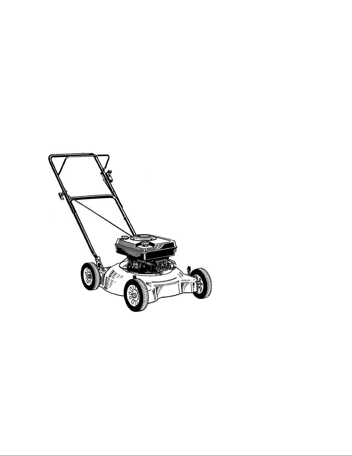
20"
MULCHING
$1.00
ROTARY
MOWER
Model Numbers
111-093R000
111-094R000
111-095R000
111-096R000
111-098R000
(Model 093R Shown)
Important: Read Safety Rules and Instructions Carefully
in
AMERICA
PRINTED IN U.S.A.
WARNING: This unit is equipped with an internal combustion engine and shouid not be used
on or near any unimproved forest-covered, brush-covered or grass-covered land unless the
engine’s exhaust system is equipped with a spark arrester meeting applicable local or state
laws (if any). If a spark arrester is used, it should be maintained in effective working order
by the operator.
In the State of California the above is required by law (Section 4442 of the California Public
Resources Code). Other states may have similar laws. Federal laws apply on federal lands.
A spark arrester for the muffler is available through your nearest engine authorized service
dealer or contact the service department, P.O. Box 360900, Cleveland, Ohio 44136.
FORM NO. 770-7427F

IMPORTANT
THIS SYMBOL POINTS OUT IMPORTANT SAFETY INSTRl ICTIONS WHICH, IF NOT FOLLOWED, COULD ENDANGER THE PERSONAL SAFETY
AND/OR PROPERTY OF YOURSELF AND OTHERS. RE/D AND FOLLOW ALL INSTRUCTIONS IN THIS MANUAL BEFORE AHEMPTING
A
TO OPERATE YOUR LAWN MOWER. FAILURE TO COMPLY WITH THESE INSTRUCTIONS MAY RESULT IN PERSONAL INJURY. WHEN
YOU SEE THIS SYMBOL- A HEED ITS WARMNG.
RULES FOR SAFE OPERATION
A
DANGER: with any type of power equ pment, carelessness or error on the part of the operator can result in serious
Your lawn mower was buill to be operated according to tbe rules for safe operation in this manual. As
A
TRAINING
Read this owner’s guide carefully in its entirety before attempting
to assemble or operate this machine. Be completely f< miliar with
the controls and the proper use of this machine befoni operating
it. Keep this manual in a safe place for future and reguli r reference
and for ordering replacement parts.
2. Your rotary mower is a precision piece of power equi iment, not
a plaything. Therefore, exercise extreme caution at all 1 mes. Your
unit has been designed to perform one job: to mow grass. Do
not use it for any other purpose.
3. Never allow children under 14 years old to operate a po\ /er mower.
Children 14 years old and over should only operate mower under
close parental supervision. Only persons well acquaintec with these
rules of safe operation should be allowed to use yo ir mower.
4. Keep the area of operation clear of all persons, partici ilarly small
children and pets. Stop engine when they are in the vicinity of
your mower to help prevent blade contact or throwr object in
jury. Although the area of operation should be complei ely cleared
of foreign objects, an object may have been overlookei I and could
be accidently thrown by the mower in any direction and cause
serious personal injury to the operator or any others allowed in
the area.
PREPARATION
Thoroughly inspect the area where the equipment is lo be used.
Remove all stones, sticks, wire, bones and other foreign objects
which could be picked up and thrown by the mower ir any direc
tion and cause serious personal injuiy to the operator oi any others
allowed in the area. Plan your mowing pattern to avoi( I discharge
of material toward roads, sidewalks, bystanders anc the like.
2. Always wear safety glasses or eye shields during operal on or while
performing an adjustment or repair, to protect eyes fi om foreign
objects that may be thrown from the machine in an f direction.
3. Wear sturdy, rough-soled work shoes and close-fitting slacks and
shirts. Shirts and pants that cover the arms and leg: and steel
toed shoes are recommended. Do not wear loose fitting clothes
or jewelry. They can be caught in moving parts. Never operate
a unit in bare feet, sandals, or sneakers.
4. Before working with gasoline, extinguish all cigarettes, c Igars, pipes
and other sources of ignition. Check the fuel level bef >re starting
the engine. Gasoline is an extremely flammable fuel Do not fill
the gasoline tank indoors, while the engine is runni ig, or until
engine has been allowed to cool for at least two m ñutes after
running. Replace gasoline cap securely and wipe off any spilled
gasoline before starting the engine as it may cause a fire or
explosion.
5. Disengage the self-propelled mechanism or drive clul ch on units
so equipped before starting the engine.
6. The blade control handle is a safety device. Never attem )t to bypass
its operation. Doing so makes the safety device inof erative and
may result in personal injury through contact with he rotating
blade. The blade control handle must operate easily ir both direc
tions and automatically return to the disengaged pos tition when
released.
7. Never attempt to make a wheel or cutting height adjus tment while
the engine is running.
8. Never operate the mower in wet grass. Always be s ure of your
footing. A slip and fall can cause serious personal i ijury. Keep
a firm hold on the handle and walk, never run. Mow onl / in daylight
or in good artificial light.
injury. If you violate any ol these rules, you may cause serious injury to yourself or others.
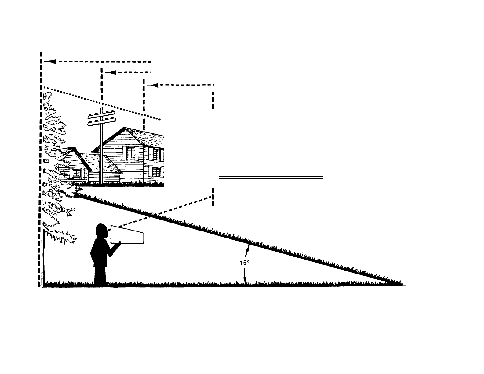
9. For your safety, use the slope gauge included as part of this manual
to measure slopes before operating this unit on a sloped or hilly
area. If the slope is greater than 15° as shown on the slope gauge,
do not operate this unit on that area or serious injury could result.
OPERATION
Do not change the engine governor settings or overspeed the
engine. Excessive engine speeds are dangerous.
Do not put hands or feet near or under rotating parts. Keep clear
of the discharge opening at all times as the rotating blade can
cause injury.
Stop the blade when crossing gravel drives, walks or roads.
After striking a foreign object, stop the engine, remove the wire
from the spark plug, and thoroughly inspect the mower for any
damage. Repair the damage before restarting and operating the
mower.
If the equipment should start to vibrate abnormally, stop the engine
5.
and check immediately for the cause. Vibration is generally a warn
ing of trouble.
Shut the engine off and wait until the blade comes to a complete
6.
stop before removing the grass catcher or unclogging the chu*'
The cutting blade continues to rotate for a few seconds after
engine is shut off. Never place any part of the body in the blau»
area until you are sure the blade has stopped rotating.
Before cleaning, repairing or inspecting, make certain the blade
and all moving parts have stopped. Disconnect the spark plug wire,
and keep the wire away from the spark plug to prevent accidental
starting.
Do not run the engine indoors.
Never cut grass by pulling mower toward you. Mow across the
face of slopes, never up-and-down. Exercise extreme caution when
changing direction on slopes. Do not mow excessively steep slopes;
Always be sure of your footing. A slip and fall can cause serious
personal injury.
Never operate mower without proper guards, plates or other safety
10.
protective devices in place.
Muffler and engine become hot and can cause a burn. Do not
11.
touch.
MAINTENANCE AND STORAGE
Check the blade and engine mounting bolts at frequent intervals
for proper tightness. Also visually inspect blade for damage (e.g.
bent, cracked). Replace with blade which meets original equip
ment specifications.
Keep all nuts, bolts, and screws tight to be sure the equipment
is in safe working condition.
Never store the mower with gasoline in the tank or gas containers
3.
inside of a building where fumes may reach an open flame or spark
(e.g. gas hot water heater). Allow the engine to cool before stor
ing in any enclosure.
To reduce fire hazard, keep the engine free of grass, leaves ar'
excessive oil.
Check the grass catcher bag frequently for wear or deteriorati^
Replace a worn or damaged bag immediately. For safety protec
tion, replace only with new bag meeting original equipment
specifications.
------
f------------------------------------------------------------------------------- Mio jnis Line--------------------------------------------------------------------------------------
USE THIS SHEET AS A GUIDE TO DETERMINE SLOPES WHERE YOU MAY NOT OPERATE SAFELY.
SIGHT AND HOLD THIS LEVEL WITH A VERTICAL TREE
A POWER POLE
A CORNER OF A BUILDING
..................
■
I
_________
................................................IT
Ac WARNING ^
OR A FENCE POST
...........
..
....................
(D
(D
T3
U)
CO
(A
(D
(D
5'
0)
(A
m
fi)
(D
■D
O
fi)
O
<D
I o
s m
(D
<D
(D
3
o
(D
Do not mow on inclines with a slope in excess of 15 degrees (a rise of approximately 2V2 feet every 10 feet). A
riding mower could overturn and cause serious injury. If operating a walk-behind mower on such a slope, it is
extremely difficult to maintain your footing and you could slip, resulting in serious injury.
Operate RIDING mowers up and down slopes, never across the face of slopes.
Operate WALK-BEHIND mowers across the face of slopes, never up and down slopes.
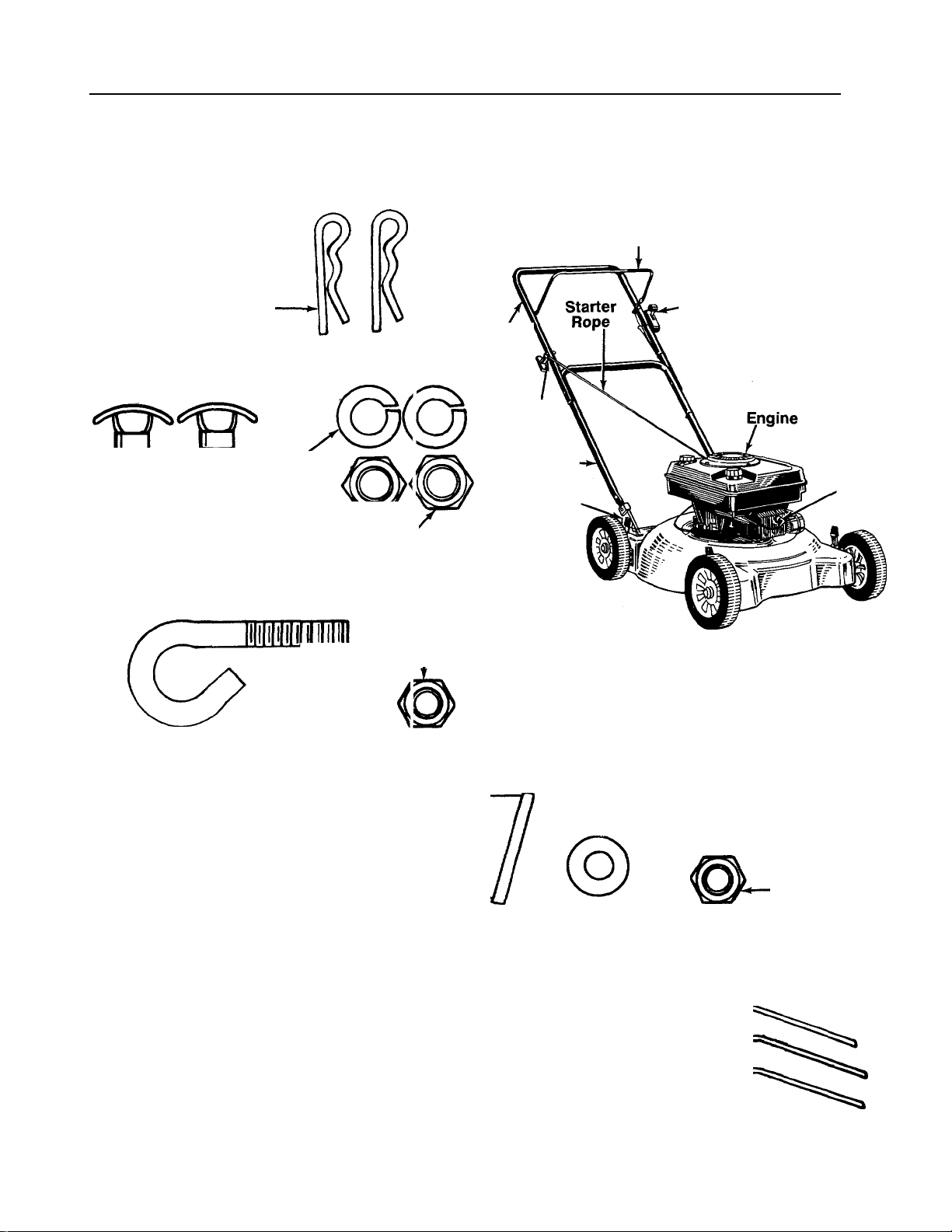
CONTENTS OF HARDWARE PACK/PARTS IDENTIFICATION
Remove this sheet from your owner’s manual e nd lay the hardware on the illustration for identification purposes.
After assembly, keep the Slope Gauge which is on the reverse side of this sheet for future use.
(Hardware pack may contain extra items which are not used on your unit. Part numbers are shown in
parentheses.)
ATTACHING THE
LOWER HANDLE
Hairpin
Clips
(714-0104)
ATTACHING THE UPPER HANDLE
В
Split Washers
5/16" I.D.
(736-0119)
Curved
—Head
Bolts
(710-0671)
ATTACHING THE STARTER ROPE
Rope
Guide
(710-1205)
Hex 'Juts
5/16-18 Thread
(712-11267)
Hex Lock Nut
V4-2( Thread
(71 >-0324)
Upper
Handle
Rope
Guide'
Lower
Handle
Handle
Mounting'
Brackets
Blade Control
Handle
Throttle
'Control
PARTS IDENTIFICATION
Spark
Plug
О
c
>
—(
3"
w
□
з‘
(D
ATTACHING THE THROTTLE CONTROL
Cable
Bracket
(17174)
/
SECURING THE CABLES
□
тж
mu
и
0
INCHES
I I I I I I
I
I I I I I I
I I I I I
2
I I
О
Spring Washer
(736-0175)
Cable Ties
(726-0240)
Vi" I.D.
Hex Bolt
V4-2O X 1-7/8" Long
(710-1216)
_____
I
J
Hex Nut
У4-20 Thread
(712-0287)
ASSEMBLY INSTRUCTIONS
IMPORTANT: This unit is shipped WITHOUT
GASOLINE or OIL. After assembly, service engine
with gasoline and oil as instructed in the separate
engine manual packed with your unit.
NOTE: Reference to right or left hand side of the
mower is observed from the operating position.
Refer to parts identification on page 4 for location
of parts when assembling the mowen
Tools Required for Assembly
(1) Pair of Pliers
(1) 1/2" Wrench or Adjustable Wrench
(2) 7/16" Wrenches or Adjustable Wrenches
(1) Flat Bladed Screwdriver
UNPACKING
1. Remove the lawn mower from the carton by open
ing the top flaps and lifting the unit out. Be careful
of the staples. Make certain all parts and literature
have been removed from the carton before the car
ton is discarded.
2. Disconnect and ground the spark plug wire against
the engine.
3. Stretch out all control cables and place on the floor.
Be careful not to bend or kink the cables at any
time during assembly.
4. Remove page four from this manual and lay the
contents of the hardware pack on the illustration
for identification.
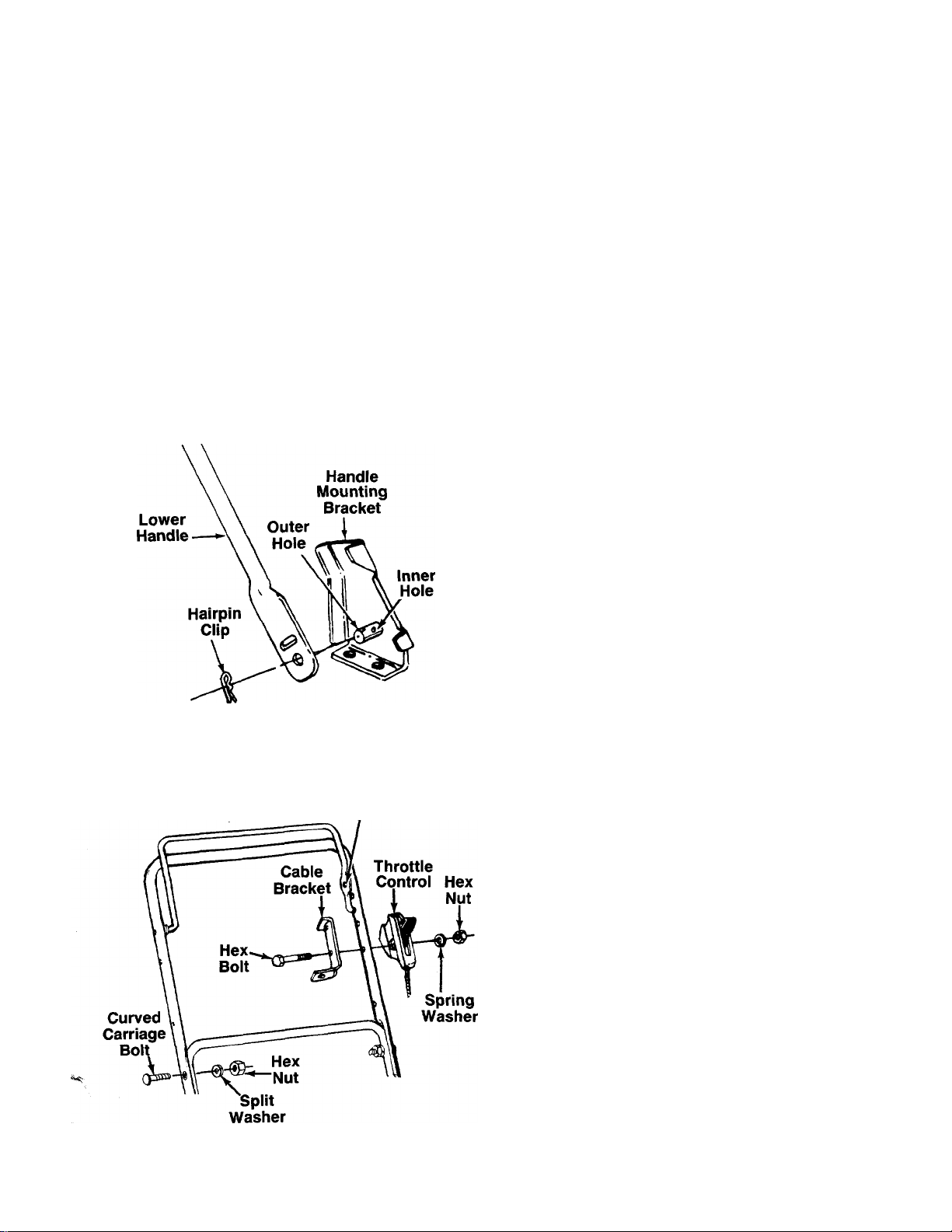
ATTACHING THE LOWER HANDLE (Hardware A)
1. Attach the lower handle by placing the bottom
holes in the lower handle over the weld pins on the
handle mounting brackets extending through the
rear of the deck.
2. Using a pair of pliers, squeeze one leg of the lower
handle against the handle mounting bracket. In
sert the hairpin clip into the hole in the weld pin.
-------
See figure 1. Repeat on other side.
FIGURE 1.
FIGURE 2.
Hole In
Blade Control
Handle
ATTACHING THE UPPER HANDLE (Hardware B)
1. Place the upper handle in position over the lower
handle. The hole in the side of the blade control
handle (attached to the upper handle) must be on
the left side.
2. Secure the upper handle to lower handle using the
curved head bolts, split washers and hex nuts as
-------
shown in figure 2.
AHACHING THE THRDHLE CDNTRDL (Hardware D)
The throttle control is attached to the engine. Attach
the throttle control to the left side of upper handle as
follows. See figure 2.
1. Route the throttle control cable inside the legs and
beneath the upper bar of the lower handle.
2. Place cable bracket against left side of upper han-
die, lining up the hole in the bracket with the bot
tom hole in upper handle. Place 1/4" hex bolt
through cable bracket and handle, from the inside
to the outside.
3. Place throttle control on the hex bolt (outside of
upper handle), with the throttle lever facing up
ward. Secure with spring washer (cupped side
against the throttle control) and hex nut.

FIGURE 3.
ATTACHING THE BRAKE CABLE
1. The brake cable is attached to the engine, and has
a “Z” fitting on the loose end. Route the brake
cable below the lower handle. Place end of cable
through the hole in the bracket as shown in figure
■3. Be careful not to bend or kink the cable at any
time. Push the plastic fitting until it locks into the
hole in the bracket.
WARNING: Brake cable must be as
sembled as shown for proper blade brake
operation.
2. Hook the “Z” end of the brake cable into the hole
A
in the blade control handle from the inside to the
outside as shown in figure 3.
SECURING THE CABLES (Hardware E)
Secure all cables to the left side of the handle as
follows.
WARNING: When attaching the control
cables, the cables must be routed to avoid
A
1.
2.
3. Trim excess ends of cable ties.
contact with all sharp edges and hot sur
faces to prevent damage to the cables,
which will render the controls inoperative.
Insert posts on cable ties into holes provided on
the handles, one on the upper handle and two on
the lower handle. The holes may be either on the
inside or outside of the handles. See figure 4A.
Secure the cables with the cable ties. See figure
4B.
FIGURE 6.—5V2" Diameter Hub Cap Shown
ATTACHING THE STARTER ROPE (Hardware C)
1. The starter rope is inside the top of the engine. Ad
ditional rope may be wound around the starter han
dle. If so, unwind the rope from the handle.
2.
With the spark plug wire disconnected and
grounded, depress the blade control handle and
pull the rope out of the engine.
Place the rope guide around the starter handle, so
3.
the rope guide bends downward as shown in figure
-------
5. Insert the rope guide into the handle, and secure
with hex lock nut.
FINAL ASSEMBLY OF MOWER
1. Place hub caps in position against the inner hub
of the wheel. To install 5V2" diameter hub caps,
press firmly around the center portion of hub cap
in a circular motion, similar to installing a lid on a
-------
round, plastic container. See figure 6. The hub
caps are flexible and will snap over wheel hubs.
NOTE: /t may be helpful to place the hub caps In hot
tap water for several minutes to make them pliable
before installing, especially if the temperature is less
than 60°F.
2. Make certain all nuts and bolts are tightened
securely.

CONTROLS
FIGURE 7.
BLADE CONTROL HANDLE
WARNING: This control mechanism is a
safety device. Never attempt to bypass its
A
The blade control handle is located on the upper han
dle of the mower. See figure 7. The blade control han
dle must be depressed in order to operate the unit.
Release the blade control handle to stop the engine and
blade.
A
THROTTLE CONTROL
The throttle control is located on the side of the upper
handle. It is used to regulate the engine speed.
operations.
WARNING: The blade will be rotating
whenever the engine is running.
WARNING: The throttle control cannot be
used to stop the engine.
Keep hands and feet away from the mowing deck. See
figure 8.
The operation of any iawn mower can result in
foreign objects being thrown into the eyes, which
can result in severe eye damage.
Aiways wear safety glasses or eye
shields. We recommend wide vision
safety mask for over spectacles or
standard safety glasses.
NOTE: For shipping purposes your mower is set with
the wheeis in a iow cutting height position. For best
results raise the cutting position until it is determined
which height is best for your lawn. See cutting height
adjustment section.
GAS AND OIL FILL-UP
Service the engine with gasoline and oil as instructed
in the separate engine manual packed with your
mower. Read instructions carefully.
WARNING: Never fill fuel tank indoors,
with engine running or until the engine has
A
TO START ENGINE AND ENGAGE BLADE
1. Attach spark plug wire to spark plug. Make certain
been allowed to cool for at least two
minutes after running.
the metal loop on the end of the spark plug wire
(inside the rubber boot) is fastened securely over
the metal tip on the spark plug. See figure 9.
Metal Loop
on Spark
Plug Wire
RECOIL STARTER
A
The recoil starter handle is attached to the handle. See
figure 7. Stand behind the unit in the operating posi
tion to start the unit.
OPERATION
Rubber Boot
FIGURE 9.
2. Open fuel shut-off valve if unit is so equipped.
Refer to separate engine manual.
3. Move throttle control lever all the way fonward.
4. Tecumseh engines only: Prime engine as in
structed in the separate engine manual packed
with your unit.
5. Standing behind the unit, depress the blade con
trol handle and hold it against the upper handle
as shown. See figure 10.
6. Grasp the recoil starter handle and pull back rapid
ly, extending rope fully. Return it slowly to the rope
guide bolt.
7. After engine starts, move throttle control to desired
engine speed.
NOTE: If any problems are encountered, refer to the
Trouble Shooting Guide on page 11.

TO STOP ENGINE AND BLADE
1. Release the blade control handle to stop the
engine and blade.
WARNING: The blade continues to rotate
for a few seconds after the engine i s shut
A
2. Disconnect the spark plug wire and ground it
off.
against the engine to prevent accidental starting
while equipment is unattended.
ADJUSTMENTS
WARNING: Do not at any time make any
adjustment to iawn mower without first
A
CUTTING HEIGHT ADJUSTMENT
An adjusting plate and thumb lever at each wheel posi
tion provides cutting height adjustment. Each adjusting
plate has nine height positions. Height of cut will be
changed when the thumb lever Is moved from one hole
to another. Simply depress the lever towards wheel and
move wheel and lever assembly to desired position. All
wheels must be placed In the same relative position.
See figure 11.
stopping engine and disconnecting spark
plug wire.
USING YOUR ROTARY MOWER
Be sure that lawn is clear of stones, sticks, wire, c r other
objects which could damage lawn mower or e ngine.
Such objects could be accidently thrown by the -power
in any direction and cause serious personal injury to
the operator and others.
For the best results, do not cut wet grass because it
tends to stick to the underside of the mower, pi event
ing proper mulching of grass clippings. In addition, wet
grass could cause you to slip and fall. New grass;, thick
grass or wet grass may require a narrower cut.
For best results, cut off one-third or less of the total
length of the grass. Lawn should be cut in the fall as
long as there is growth.
This mower is designed to be operated at full ihrottle
to give you the best cut and do the most effective job
of mulching.
WARNING: If you strike a foreign cibject,
stop the engine. Remove wire from spark
A
plug, thoroughly inspect the mower 1 or any
damage, and repair the damage before
restarting and operating the mower. Exten
sive vibration of the mower during opera
tion is an indication of damage. Tf e unit
should be
repaired.
promptly inspectée and
FIGURE 11.
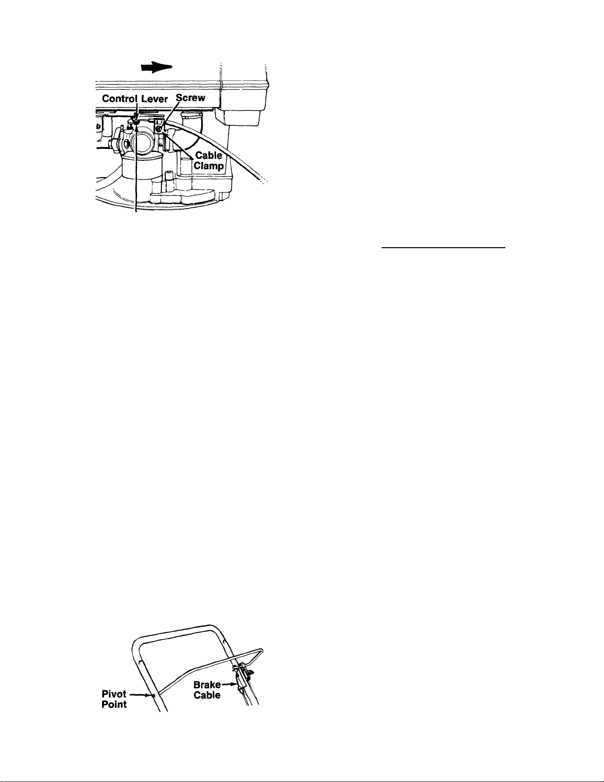
THROTTLE CONTROL ADJUSTMENT
If the throttle control requires adjustment or has been
replaced, adjust as follows.
1. Remove the screw shown in figure 12. Remove the
cable clamp from the cable.
2. Push the throttle control lever on the handle all the
way forward to CHOKE or START position. Make
certain the throttle control lever remains in this
position.
3. Push the control lever on the engine as far toward
the rear of the engine as it will go. Secure the cable
in this position with the cable clamp and screw.
Cable
Clamp,
FIGURE 12A.—Briggs & Stratton Quantum Engine
“Z” End
of Cable
FIGURE 12B.—Tecumseh Premier Engine
Wheels—Mower may be provided with ball bearing
wheels. Lubricate at least once a season with light oil.
Also, if the wheels are removed for any reason,
lubricate the surface of the axle bolt and the inner sur
face of the wheel with light oil. A4 oz. plastic bottle
of light oil lubricant is available. Order part number
737-0170. Engine oil may also be used.
Engine—Follow engine manual for lubrication in
structions.
Throttle—Periodically lubricate throttle control lever
and throttle wire assembly with a few drops of light oil
for ease of operation.
MAINTENANCE
CARBURETOR ADJUSTMENTS
WARNING: If any adjustments are made to
the engine whiie the engine is running (e.g.
A
Minor carburetor adjustments may be required to
compensate for differences in fuel, temperature,
altitude and load. To adjust carburetor, refer to the
separate engine manual packed with your mower.
NOTE: A dirty air cieaner will cause an engine to run
rough. Be certain air cleaner is clean and attached to
the carburetor before adjusting carburetor. Refer to the
separate engine manual.
carburetor), keep clear of all moving parts.
Be careful of heated surfaces and muffler.
LUBRICATION
WARNING: Always stop engine and
disconnect spark piug wire before clean
A
Blade Control—Lubricate the pivot points on the blade
control handle and the brake cable at least once a
season with light oil. See figure 13. The blade control
must operate freely in both directions.
FIGURE 13.
ing, lubricating or doing any kind of work
on lawn mower.
WARNING: Be sure to disconnect and
ground the spark plug wire before per
A
NOTE: When tipping the unit, empty the fuel tank and
keep engine spark plug side up.
forming any repairs or maintenance.
TROUBLE SHOOTING
Refer to page 11 of this manual for trouble shooting
information.
CUTTING BLADE
When removing the cutting blade for sharpening or
replacement, protect hands by using heavy gloves or
a rag to grasp the cutting blade. Remove the bolt and
bell washer which hold the blade and adapter to the
engine crankshaft. Remove the blade and adapter from
the crankshaft.
If the blade or blade adapter needs replacing, remove
the two small bolts, lock washers and nuts which hold
the blade to the adapter.
WARNING: Periodically inspect the blade
adapter for cracks, especially if you strike
A
When sharpening the blade, follow the original angle
of grind as a guide. It is extremely important that each
cutting edge receives an equal amount of grinding to
prevent an unbalanced blade. An unbalanced blade will
cause excessive vibration when rotating at high speeds,
may cause damage to the mower and could break,
causing personal injury.
It is recommended that the blade always be removed
from the adapter for the best test of balance. The blade
can be tested by balancing it on a round shaft
screwdriver. Remove metal from the heavy side until
it balances evenly.
Before reassembling the blade and the blade adapter
to the unit, lubricate the engine crankshaft and the inner
a foreign object. Replace when necessary.

surface of the blade adapter with light oil. Lubric ating
the bolt holes, bolts and inner surface of the nuti; with
light oil is also recommended. A 4 oz. plastic bo:tle of
light oil lubricant is available. Order part nimber
737-0170. Engine oil may also be used.
When replacing the blade, be sure to install the olade
with the side of the blade marked “Bottom” (o- with
part number) facing the ground when the mowe' is in
the operating position.
Blade Mounting Torque
Center Bolt and Blade Adapter Bolts: 375 in. lb. min.,
450 in. lb. max.
To insure safe operation of your unit, all nuts anc bolts
must be checked periodically for correct tightn 3ss.
DECK
The underside of the mower deck should be cloaned
after each use to prevent a buildup of grass clippings,
leaves, dirt or other matter. If this debris is allov/ed to
accumulate, it will invite rust and corrosion, and may
prevent proper mulching.
The deck may be cleaned by tilting the mower and
scraping clean with a suitable tool (make certain the
spark plug wire is disconnected).
OFF-SEASON STORAGE
The following steps should be taken to prepare lawn
mower for storage.
1. Clean and lubricate mower thoroughly as de
scribed in the lubrication instructions.
2. Refer to engine manual for correct engine storage
instructions.
3. Coat mower’s cutting blade with chassis grease
to prevent rusting.
4. Store mower in a dry, clean area.
NOTE: When storing any type of power equipment in
an unventiiated or metai storage shed, care shouid be
taken to rust-proof the equipment. Using a iight oii or
silicone, coat the equipment, especially cables and all
moving parts.
ENGINE
Refer to the separate engine manual for eigine
maintenance instructions.
Maintain engine oil as instructed in the separate
engine manual packed with your unit. Read and follow
instructions carefully.
Service air cieaner every 25 hours under norms 1 con
ditions. Clean every few hours under extremely dusty
conditions. Poor engine performance and flooding
usually indicates that the air cleaner should be ser
viced. To service the air cleaner, refer to the separate
engine manual packed with your unit.
The spark plug should be cleaned and the gap reset
once a season. Spark plug replacement is rscornmended at the start of each mowing season; check
engine manual for correct plug type anc gap
specifications.
Clean the engine regularly with a cloth or brush Keep
the cooling system (blower housing area) clean :o per
mit proper air circulation which is essential to ongine
performance and life. Be certain to remove all grass,
dirt and combustible debris from muffler area.
HANDLE STORAGE
The handle may be placed in an upright position for
storage. Press inward on the bottom of the lower han
dle and push forward. The handle will lock in this
position.
To place the handle in the operating position, remove
the starter rope from the rope guide bolt. Grasp the
lower handle at the bottom, press inward slightly and
tip the handle backward. With the spark plug wire
disconnected and grounded, depress the blade con
trol handle and pull the starter rope out from the engine.
Slip the starter rope into the rope guide bolt.
10

TROUBLE SHOOTING GUIDE
Trouble
Engine fails to start 1. Blade control handle disengaged.
Engine runs erratic 1. Unit running in CHOKE or START position.
Engine overheats 1. Engine oil level low.
Occasional skip
(hesitates) at high speed
2. Spark plug wire disconnected.
3. Throttle control lever not in CHOKE
or START position.
4. Fuel shut-off valve closed (if so equipped).
5. Fuel tank empty, or stale fuel.
6. Blocked fuel line.
7. Faulty spark plug.
8. Engine flooded.
2. Spark plug wire loose.
3. Blocked fuel line or stale fuel.
4. Vent in gas cap plugged.
5. Water or dirt in fuel system.
6. Dirty air cleaner.
7. Carburetor out of adjustment.
2. Air flow restricted.
3. Carburetor not adjusted properly.
1. Spark plug gap too close.
2. Carburetor idle mixture adjustment
improperly set.
Possible Cause(s) Corrective Action
1. Engage blade control handle.
2. Connect wire to spark plug.
3. Move throttle lever to CHOKE or
START position.
4. Open fuel shut-off valve.
5. Fill tank with clean, fresh gasoline.
6. Clean fuel line.
7. Clean, adjust gap or replace.
8. Remove spark plug, dry the plug, and
crank engine with plug removed and
throttle in off position. Replace spark
plug, connect wire and resume starting
procedures.
1. Move throttle lever to FAST position.
2. Connect and tighten spark plug wire.
3. Clean fuel line; fill tank with clean,
fresh gasoline.
4. Clear vent.
5. Drain fuel tank. Refill with fresh fuel.
6. Clean air cleaner.t
7. Adjust carburetor.f
1. Fill crankcase with proper oil.
2. Remove blower housing and clean.!
3. Adjust carburetor.!
1. Adjust gap to .030".
2. Adjust carburetor.!
Idies poorly 1. Spark plug fouled, faulty or gap too wide.
Excessive vibration 1. Cutting blade loose or unbalanced.
Mower will not
mulch grass
Uneven cut
2. Carburetor improperly adjusted.
3. Dirty air cleaner.
2. Bent cutting blade.
1. Engine speed too low.
2. Wet grass.
3. Excessively high grass.
4. Dull blade.
1. Wheels not positioned correctly.
2. Dull blade.
1. Reset gap to .030" or replace spark plug.
2. Adjust carburetor.!
3. Clean air cleaner.!
1. Tighten blade and adapter.
Balance blade.
2. Replace blade.
1. Set throttle between 3/4 and full throttle.
2. Do not mow when grass is wet; wait until
later to cut.
3. Mow once at a high cutting height, then
mow again at desired height or make a
narrower cutting swath (1/2 width).
4. Sharpen or replace blade.
1. Place all four wheels in same
height position.
2. Sharpen or replace blade.
tRefer to separate engine manual packed with your unit.
Note: For repairs beyond the minor adjustments listed above, contact your locai authorized service dealer.
11

Models 093R through 098R
■5b XF -BUNDG. f)\T5 ZhFfiJE
LooseM £MC..‘1'?RY Fotu>A«D. /5
IF “BuMie stiLl liiTS 'BftFFl.E. S/nflCK.
'BAfFi-G uOTTrt For
¿LleA/EAUCEI .
■11^ note
This instruction manuai covers various models, and
ail specifications shown do not necessarily apply to
your model. Specifications subject to change
without notice or obligation.
12

Models 093R thru 098R
PARTS LIST FOR MODEL 098R MULCHING ROTARY MOWER
<EF.
NO.
10 710-1205
11
12
13 710-0671
14
15 749-0372B
16 714-0104
17
18
19 12935A
20 12936A Handle Bracket Ass’y.—R.H.
21
22
23
24
29 682-0002 638/N 20" Deck Ass’y.
^30 753-0485 Blade Adapter Kit (Splined)
J1
PART
NO.
1 747-0748
731-1135
CODE DESCRIPTION
Control Handle Ass’y- (Std.)
Control Handle Ass’y- w/Plastic
REF.
NO.
33 742-0500 20" Mulching Blade
34
710-1055
3 17174 Cable Brkt. 35 736-0169
4 710-1216
Hex Bolt 1/4-20 X 1.875" Lg.
712-0241 Hex Nut 3/8-24 Thd.
36
5 736-0175 Spr. Wash. 1/4" I.D. 37 712-0324
712-0287
6
7
720-0226 Grip (Optional) 44 735-0639
8 749-0756A
736-0119 L-Wash. 5/16" I.D.*
712-0267
Hex Nut 1/4-20 Thd.* 39
Upper Handle 46 738-0102
N
Rope Guide Bolt 47 736-0105
Hex Nut 5/16-18 Thd.*
48 738-0507B
49 14832
Curved Carriage Bolt 5/16-18 50 15262B
X 1.38" Lg.
726-0240 Cable Tie 52
Lower Handle
51 15261A
★ *
53 14578 Height Adj. Ass’y. Comp.—
Hairpin Cotter
17098 Hinge Clip
14579 Height Adj. Ass’y. Comp.—
731-0872 Rear Flap
Handle Bracket Ass’y.—L.H. 54
746-0820
746-0834
736-0356 Bell-Wash. .39" I.D. x 1.38"
712-0798 Hex Nut 3/8-16 Thd.*
* *
* *
Hub Cap (Optional) 57
Wheel Bearings
55 746-0553
746-0737
710-0654A
736-0232
58
59 710-0603
736-0453 Bell-Wash. .46" I.D.
710-0757
Hex Bolt 7/16-20 x 1.5" Lg.
PART
NO.
—
CODE
DESCRIPTION
Hex Bolt 3/8-24 x 1" Lg.
L-Wash. 3/8" I.D.*
Hex L-Nut 1/4-20 Thd.
Engine
Spark Plug Boot
Axle Bolt
Bell-Wash. .400" I.D. x .88"
Shid. Bolt .50" Dia. x .357"
Spring Lever Ass’y. w/Knob
Pivot Bar
Height Adj. Plate
Wheel Ass’y. Comp.
R.F. & L.R.
L.F. & R.R.
Throttle Control Ass’y.tt
Throttle Control Ass’y.t
Control Cable—36" tt
Control Cablet
Hex L-Wash. Hd. Scr.
3/8-16 X 1.0" Lg.
Wave Washer .53" I.D.
Hex Wash. Hd. B-Tap Scr.
5/16-18 x .5" Lg.
tModel 093R & 095R only.
ttModels 094R, 096R & 098R only.
*For faster service obtain standard nuts, bolts and washers locally.
If these items cannot be obtained locally, order by part number and
size as shown on parts list.
*’Optional Hub Caps RiLF. 23
Description
Gray (for “S” Wave Wheels)
Beige (for “S” Wave Wheels)
Black (IV2" Dia.)
Part No.
731-0981A
731-0982A
720-0251
’WHEEL CHART
WHEELS W/O BEARINGS
TREAD”’ ASS’Y. COMP. TREAD”’ ASS’Y. COMP.
Bar
Diamond 734-1655 “S” Wave
“S” Wave 734-1512A
734-1608
"S” Wave 734-1513B (Gray)
734-1517B (Beige)
CODE: N notates a new part (not previously existing). A three digit
number is the color code. Specify color code if color or finish is
important when ordering parts, [i.e., 638 for Red Finish],
NOTE: The engine is not under warranty by
the mower manufacturer. .. If repairs or
service is needed on the engine, please
contact your nearest author
ized engine service outlet.
Check the “Yellow Pages” of
your telephone book under
“Engines—Gasoline.”
WHEELS WITH BEARINGS
BEARINGS
Ball Brg. V2" I.D.—741-0180 (2 per wheel)
Ball Brg. 1/2" I.D.—741-0180 (2 per wheel)
Find It Fast
In The
Yellow Pages
’Tread Type: Waffle
Rib
: Bar
13
‘T” Tread
“S” Wave ; Diamond

A
NOTE: The use of any accessory on this Rotary Mower other than those
manufactured by the mower manufacturer is not recommended.
WARNING: To reduce the risk of injury, do not operate mower unless rear
trailing shield is in its proper place.
14


REPLACEMENT PARTS • P.O. BOX 360900 • CLEVELAND, OHIO 44136
 Loading...