


OWNEirS GUIDE
AMERICAN AMERICAN
MADE OWNED
OUTDOOR POWER EQUIPMENT
Important: Read Safety Rules and Instructions Carefully
Model Series
20" and 21 "
MULCHING
ROTARY MOWERS
105 thru 108
(Push)
130 thru 148
(Self-Propelled)
730 thru 738
(Push)
WARNING: This unit is equipped with an internal combustion engine and should not be used on or near any
unimproved forest-covered, brush-covered or grass-covered land unless the engine’s exhaust system is equipped
with a spark arrester meeting applicable local or state laws (if any). If a spark arrester is used, it should be
maintained in effective working order by the operator.
In the State of California the above is required by law (Section 4442 of the California Public Resources Code).
Other states may have similar laws. Federal laws apply on federal lands. A spark arrester for the muffler is avail
able through your nearest engine authorized service dealer or contact the service department, P.O. Box 368022,
"•N
Cleveland, Ohio 44136-9722.
MTD PRODUCTS INC • P.O. BOX 368022 • CLEVELAND, OHIO 44136-9722
PRINTED IN U.S.A. FORM NO. 770-8558J

IMPORTANT
THIS SYMBOL POINTS OUT IMPORTANT SAFETY lIJSTRUCTIONS WHICH, IF NOT FOLLOWED, COULD ENDANGER THE PERSONAL
SAFETY AND/OR PROPERTY OF YOURSELF AND )THERS. READ AND FOLLOW ALL INSTRUCTIONS IN THIS MANUAL BEFORE
A
ATTEMPTING TO OPERATE YOUR LAWN MOWER. FAILURE TO COMPLY WITH THESE INSTRUCTIONS MAY RESULT IN PERSONAL
INJURY. WHEN YOU SEE THIS SYMBOL— ^ HELD ITS WARNING.
Your lawn mower was b lilt to be operated according to the rules for sate operation in this manual. As
DANGER:
A
TRAINING
1. Read this owner’s guide carefully in its entirety before attempt
ing to assemble or operate this machine. Be compì 3tely famil
iar with the controls and the proper use of this mac line before
operating it. Keep this manual in a safe place for future and
regular reference and for ordering replacement parts.
2. Your rotary mower is a precision piece of power squipment,
not a plaything. Therefore, exercise extreme caution at all
times. Your unit has been designed to perform une job: to
mow grass. Do not use it for any other purpose.
3. Never allow children under 14 years old to operate a power
mower. Children 14 years old and over should only operate
mower under close parental supervision. Only psrsons well
acquainted with these rules of safe operation should be
allowed to use your mower.
4. Keep the area of operation clear of all persons, rarticularly
small children and pets. Stop engine when they are in the
vicinity of your mower to help prevent blade contac: or thrown
object injury. Although the area of operation shou d be com
pletely cleared of foreign objects, an object may have been
overlooked and could be accidentally thrown by th ; mower in
any direction and cause serious personal injury to t ie operator
or any others allowed in the area.
PREPARATION
1. Thoroughly inspect the area where the equipment is to be
used. Remove all stones, sticks, wire, bones and o her foreign
objects which could be picked up and thrown by tha mower in
any direction and cause serious personal injury to tie operator
or any others allowed in the area. Plan your mowing pattern to
avoid discharge of material toward roads, sidewalks,
bystanders and the like.
2. Always wear safety glasses or eye shields during operation or
while performing an adjustment or repair, to protec: eyes from
foreign objects that may be thrown from the mac line in any
direction.
3. Wear sturdy, rough-soled work shoes and close-filing slacks
and shirts. Shirts and pants that cover the arms and legs and
steel-toed shoes are recommended. Do not wear bose fitting
clothes or jewelry. They can be caught in moving [ arts. Never
operate a unit in bare feet, sandals, or sneakers.
4. Before working with gasoline, extinguish all cigare tes, cigars,
pipes and other sources of ignition. Check the fuel evel before
starting the engine. Gasoline is an extremely flammable fuel.
Do not fill the gasoline tank indoors, while the engine is run
ning, or until engine has been allowed to cool for it least two
minutes after running. Replace gasoline cap secure y and wipe
off any spilled gasoline before starting the enginu as it may
cause a fire or explosion.
5. Disengage the self-propelled mechanism or drivu clutch on
units so equipped before starting the engine.
6. The blade control handle is a safety device. Never attempt to
bypass its operation. Doing so makes the safety de rice inoper
ative and may result in personal injury through contact with the
rotating blade. The blade control handle must operite easily in
both directions and automatically return to the disengaged
position when released.
7. Never attempt to make a wheel or cutting height adjustment
while the engine is running.
8. Never operate the mower in wet grass. Always be ; ure of your
footing. A slip and fall can cause serious personal njury. Keep
a firm hold on the handle and walk, never run. N ow only in
daylight or in good artificial light.
with any type of power e iuipment, carelessness or error on the part of the operator can result in serious
injury. If you violate any i if these rules, you may cause serious injury to yourself or others.
SAFE OPERATION PRACTICES
à
9. For your safety, use the slope gauge Included as part of this
rhanual to measure slopes before operating this unit on a
sloped or hilly area. If the slope is greater than 15° as shown
oh the slope gauge, do not operate this unit on that area or
serious injury could result.
. OPERATION
1. Do not change the engine governor settings or overspeed the
engine. Excessive engine speeds are dangerous.
2. Do not put hands or feet near or under rotating parts. Keep
clear of the discharge opening at all times as the rotating blade
can cause injury.
3. Stop the blade when crossing gravel drives, walks or roads.
4. After striking a foreign object, stop the engine, remove the wire
from the spark plug, and thoroughly inspect the mower for any
damage. Repair the damage before restarting and operating the
mower.
5. If the equipment should start to vibrate abnormally, stop the
engine and check immediately for the cause. Vibration is gen
erally a warning of trouble.
6. Shut the engine off and wait until the blade comes to a com
plete stop before removing the grass catcher or unclogging the
chute. The cutting blade continues to rotate for a few seconds
after the engine is shut off. Never place any part of the body in
the blade area until you are sure the blade has stopped rotat
ing.
7. Before cleaning, repairing or inspecting, make certain the blade
and all moving parts have stopped. Disconnect the spark plug
wire, and keep the wire away from the spark plug to prevent
'accidental starting.
8. Do not run the engine indoors.
9. Never cut grass by pulling mower toward you. Mow across the
face of slopes, never up-and-down. Exercise extreme caution
when changing direction on slopes. Do not mow excessively
steep slopes. Always be sure of your footing. A slip and fall can
cause serious personal injury.
10. Never operate mower without proper guards, plates or other
safety protective devices in place.
11. Muffler and engine become hot and can cause a burn. Do not
touch.
MAINTENANCE AND STDRAGE
1. Check the blade and engine mounting bolts at frequent inter
vals for proper tightness. Also visually inspect blade for dam
age (e.g. bent, cracked). Replace with blade which meets origi
nal equipment specifications.
2. Keep all nuts, bolts, and screws tight to be sure the equipment
is in safe working condition.
3. Never store the mower with gasoline in the tank or gas con
tainers inside of a building where fumes may reach an open
flame or spark (e.g. gas hot water heater). Allow the engine to
cool before storing in any enclosure.
4. To reduce fire hazard, keep the engine free of grass, leaves and
excessive oil.
5. Check the grass catcher bag frequently for wear or deteriora
tion. Replace a worn or damaged bag immediately. For safety
protection, replace only with new bag meeting original equip
ment specifications.
SET-UP INSTRUCTIONS
IMPORTANT: This unit is shipped WITHOUT GASO
LINE or OIL. Be certain to service engine with gaso
line and oil as instructed in the separate engine
manual before operating your mower.
NOTE: Reference to right or left hand side of the
mower is observed from the operating position.
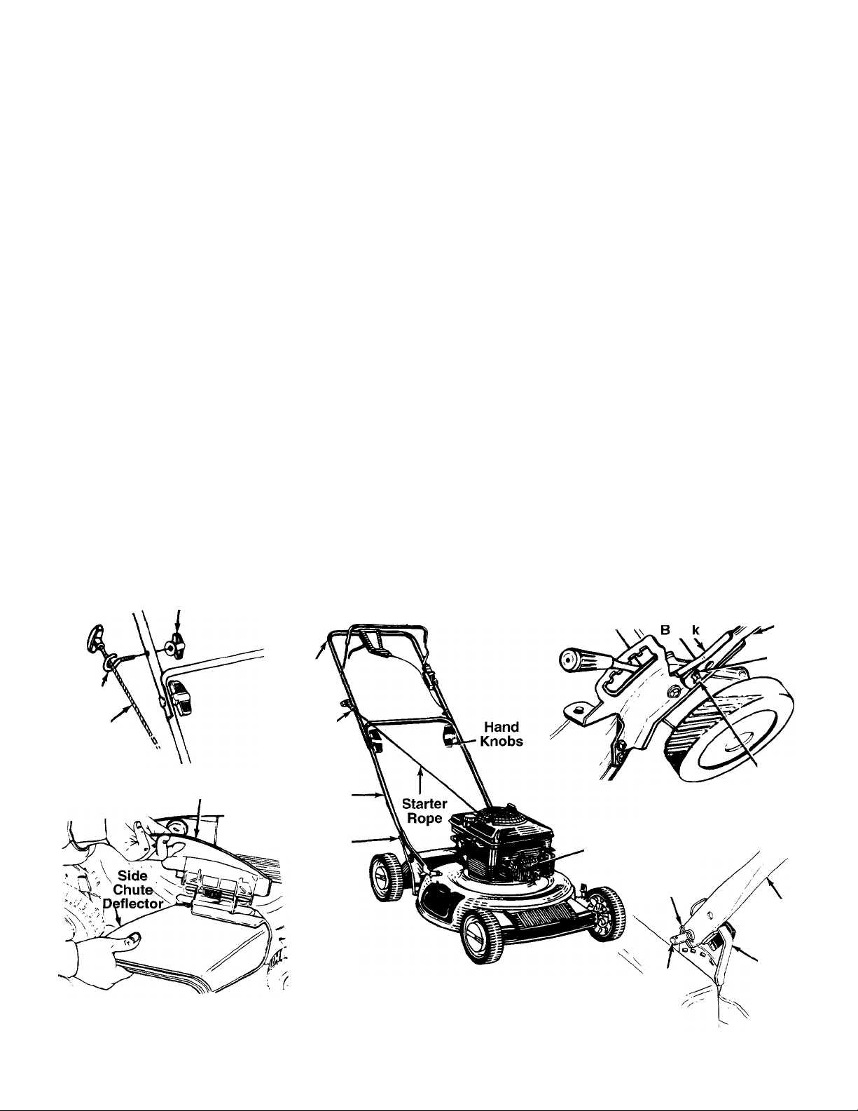
HOW TO SET-UP YOUR LAWN MOWER
Refer to Illustration Below
1. Remove carton inserts (if any) and the side dis
charge chute which is loose in the carton. Lift the
mower from the carton, or cut the corners of the
carton and roll the mower out.
2. Remove any cardboard pieces which may be
between the upper and lower handles for ship
ping purposes. If there is any packaging (plastic
or cardboard) around the upper handle, remove
it.
3. Disconnect the spark plug wire and move it away
from the spark plug.
4. Pull up and back on the upper handle to raise the
handle into the operating position. Make certain
the lower handle is seated securely into the han
dle mounting brackets. Tighten the hand knobs
on each side of the handle.
NOTE: Your mower is shipped with the handie in the
higher height position. If you wish to lower the height of
the handle, refer to the Adjustment Section at this time.
Wing Nut Handle
Upper
Rope
Guide
Starter
Rope
Muiching
Piug
Handle
Rope
Guide
Lower
Handle
Blade Control
Remove the hairpin clips from the outer hole in
the weld pins on the handle mounting brackets.
Place the hairpin clips in the inner hole.
The rope guide and wing nut are attached to the
starter rope, on top of the engine. Remove the
wing nut from rope guide. Remove the rope guide
from the starter rope.
7.
With the spark plug’wire disconnected and
grounded, hold the blade control handle against
the upper handle, and pull the starter rope out of
the engine. Hold the rope guide as shown so the
opening in the rope guide is toward the front of
mower. Slip the rope guide around the starter rope
and into the right side of upper handle using the
hole shown. Secure using the wing nut.
8.
Make certain all nuts and bolts are tightened
securely.
Your mower has been shipped as a mulcher. To dis
charge grass to the side, proceed with step 9.
9. To convert your mower from a mulcher to a
side discharge mower, lift the mulching plug.
Slide the two hooks on the side discharge deflec
tor under the hinge pin on the mulching plug
assembly. Lower the mulching plug.
SELF-PROPELLED MODELS:
Handle
Mounting
Bracket
Lower
Handle
Hairpin Clip
in Inner
Weld
Pin
Hole
Handie
Mounting
Bracket
FIGURE 1.—Self-Propelled Model Shown
Spark
Plug
PUSH MODELS:
Hairpin
Clip in
inner Hoie
Weld
Pin
Lower
Handie
Handie
Mounting
Bracket

CONTROLS
I I
Blade
Control
Handle
Drive
Clutch
Control
Recoil
Starter
FIGURE 2.—Self-Propelled 6-Speed Model Shown
1 hrottle
Control
BLADE CONTROL HANDLE
WARNING: This controi mechanism is a
safety device. Never attempt to bypass
A
The blade control handle is located on the upper han
dle of the mower. See figure 2. The blade control han
dle must be depressed in order to operate the unit.
Release the blade control handle to stop the engine
and blade.
its operations.
WARNING: The blade will be -otating
whenever the engine is running.
A
WARNING: The throttle control cannot be
used to stop the engine.
▲
RECOIL STARTER
The recoil starter handle is attached to the handle.
See figure 2. Stand behind the unit in the operating
position to start the unit.
DRIVE CLUTCH CONTROL
(Self-Propelled Models Only)
Squeezing the drive clutch control engages the drive
mechanism to the rear wheels. Releasing the clutch
control stops the rear wheels from driving. Release
the drive clutch control to slow down when negotiating
an obstacle, making a turn or stopping. See figure 2.
SHIFT LEVER
The six speed shift lever is located on the drive clutch
control housing on the upper handle. See figure 2.
This lever is used to select the operating speed of the
mower. Release the drive clutch control when chang
ing speeds.
(Six Speed Models Only)
THROTTLE CONTROL
The throttle control is located on the left si(ie of the
upper handle. It is used to regulate the engimj speed.
OPERATION
TO REDUCE THE RISK OF INJURY, DO N
OPERATE MOWER UNLESS REAR TRAILII
SHIELD AND THIS GUARD OR ENTII
GRASS CATCHER IS IN ITS PROPER PLAC
KEEP HANDS and FEET AWAY
FIGURE 3.
Keep hands and feet away from the chute area on
cutting deck. See figure 3.
IMPORTANT: Move the shift iever ONLY when the
engine is running. Shifting the speeds with the
engine off can cause damage to the unit.
The operation of any lawn mower can result in for
eign objects being thrown into the eyes, which
can result in severe eye damage.
^sAFEnTGuisrej^ Always wear safety glasses or eye
shields. We recommend wide vision
safety mask for over spectacles or
standard safety glasses.
NOTE: For best results raise the cutting position until
it is determined which height is best for your lawn.
See cutting height adjustment section.
GAS AND OIL FILL-UP
Service the engine with gasoline and oil as
instructed in the separate engine manual. Read
instructions carefully.
WARNING: Never fill fuel tank Indoors,
with engine running or until the engine
A
has been allowed to cool for at least two
minutes after running.

BEFORE STARTING
^ 1. Self-Propelled Models Only: Before each use,
check for proper drive clutch operation by per
forming the following before starting the engine:
With the drive clutch control released, push
mower forward. It should move freely. Pull mower
backward. It should move with only a small
amount of resistance.
If it does not and the rear wheels tend to lock up,
the clutch may not be releasing completely. Do
not start the engine until corrections have been
made. Check the control cable for severe bend
kinks and binding, or grass build-up around the
belt. Correct and adjust as required. Refer to
instructions under “Drive Clutch Control Adjust
ment” in Adjustment Section for loosening the
drive belt.
2. Attach spark plug wire to spark plug. Make cer
tain the metal loop on the end of the spark plug
wire (inside the rubber boot) is fastened securely
over the metal tip on the spark plug. See figure 4.
Metal Loop
on Spark
Plug Wire
Rubber Boot
N
FIGURE 4.
TO START ENGINE AND ENGAGE BLADE
(Six Speed Models Only)
IMPORTANT: Move the shift lever only when the
engine is running. Shifting the speeds with the engine
off can cause damage to the unit. Disengage the drive
clutch control when shifting speeds.
WARNING (Self-Propelled Models): When
starting the unit for the first time, place
A
All Units:
1. Move the throttle control lever to all the way for
2. Prime engine as instructed in the engine manual.
3. Standing behind the unit, depress the blade con
mower in first speed (siow) position (six
speed models only). Face the mower
against a solid object such as a wail,
fence, etc. Start the unit, and if it shows
any signs of motion with the drive ciutch
control disengaged, shut the engine off
immediately. Make certain the drive
clutch control is adjusted so the drive
belt is as loose as possible. Refer to the
Adjustment Section.
ward.
trol handle and hold it against the upper handie.
Make certain drive clutch control handle (self-pro
pelled models only) is released.
4. Grasp starter handle and pull rope out slowly until
engine reaches start of compression cycie (rope
will pull slightly harder at this point). Let the rope
rewind slowly.
5. Pull rope with a rapid, continuous, fuli arm stroke.
Keep a firm grip on starter handie. Return it slow
ly to the rope guide.
6. After engine starts, move throttle control to FAST
or desired engine speed.
NOTE: If any problems are encountered, refer to the
Trouble Shooting Guide on page 10.
TD STDP ENGINE AND BLADE
1. Reiease the blade control handle to stop the
engine and blade.
WARNING: The blade continues to rotate
for a few seconds after the engine is shut
A
2. Disconnect the spark plug wire and ground it
off.
against the engine to prevent accidental starting
while equipment is unattended.
USING YDUR RDTARY MDWER
Be sure that lawn is clear of stones, sticks, wire, or
other objects which could damage lawn mower or
engine. Such objects could be accidently thrown by
the mower in any direction and cause serious person
al injury to the operator and others.
For the best results, do not cut wet grass because it
tends to stick to the underside of the mower, prevent
ing proper discharge of grass ciippings, and couid
cause you to slip and faii. New grass, thick grass or
wet grass may require a narrower cut. Speed of the
mower should be adjusted to the condition of the lawn.
When using the side discharge mower, the best mow
ing pattern is one that allows the clippings to dis
charge towards the uncut part of the lawn. This per
mits recutting of the clippings to further pulverize
them. When cutting high weeds, discharge towards
cut portion, then recut at right angles to first direction.
For a healthier lawn, always cut off one-third or
less of the total length of the grass. Lawn should
be cut in the fall as long as there is growth.
This mower is designed to be operated at full throttle
to give you the best cut and do the most effective job
of mowing.
WARNING: If you strike a foreign object,
stop the engine. Remove wire from spark
A
plug, thoroughly inspect the mower for
any damage, and repair the damage
before restarting and operating the
mower. Extensive vibration of the mower
during operation is an indication of dam
age. The unit should be promptly
inspected and repaired.

ADJUSTMENTS
WARNING: Do not at any time miike any
adjustment to lawn mower withe ut first
A
CUTTING HEIGHT ADJUSTMENT
Push Modeis:
An adjusting plate and thumb lever at each wheel
position provides cutting height adjustment. Each
adjusting plate has nine height positions. Heigit of cut
will be changed when the thumb lever is moved from
one hole to another. Simply depress the lever towards
wheel and move wheel and lever assembly to desired
position. All wheels must be placed in the same rela
tive position. See figure 5A.
stopping engine and disconnecting spark
piug wire.
I I
HANDLE HEIGHT ADJUSTMENT
Your mower is shipped with the handle in the higher
height position. To lower the handle height, proceed
as follows.
1. Remove the starter rope from the rope guide.
2. Remove the upper handle by removing the hand
knobs and carriage bolts. Lay the upper handle
out of the way, being careful not to bend or kink
the cables.
3. Remove the hairpin clips from the weld pins on the
handle brackets. For push models, press inward
on the legs of the lower handle. Press outward on
the legs of the lower handle for self-propelled mod
els. Remove lower handle from the mower.
4. Turn the lower handle around so the notches on
the bottom of the lower handle are facing forward
as shown in figure 6. Reassemble, placing the
bottom holes in the handle over the weld pins in
the handle mounting bracket.
5. Reassemble the upper handle.
6. Place the hairpin clips in the inner holes in the
weld pins and attach the starter rope as instruct
ed in the Set-Up Instructions.
FIGURE 5A.—Push Models
Self-Propelled Models:
The height adjustment handles for the whisels are
located on the left side of the deck. The hancles may
be placed in one of nine cutting height positiens. See
figure 5B.
For rough or uneven lawns, move the heigh adjust
ment handles to positions which will give a hie her cut
ting height. Both front and rear handles nust be
placed in the same relative position.
Lower
Handle
Notch
FIGURE 6.
DRIVE CLUTCH CONTRDL ADJUSTMENT
(Self-Propelled Models Only)
Use the adjustment wheel located in the clutch control
housing to tighten the drive belt if mower does not selfpropel with the drive clutch control engaged, or if drive
belt is slipping (unit hesitates while engine maintains
the same speed). See figure 7.
In addition, the adjustment wheel may also be used to
determine the position in which the drive clutch control
is engaged. If it is more comfortable to have the drive
engaged with the lever further away from the handle,
tighten the drive belt.
Make certain to retest the unit for neutral as instructed
in the Operation Section. Move the adjustment wheel
in the opposite direction to loosen the drive belt if nec
essary.

FIGURE 7.
THROTTLE CONTROL ADJUSTMENT
If the throttle control requires adjustment or if it has
been replaced, adjust the throttle control as follows.
1. Remove the screw shown in figure 8. Remove the
cable clamp from the cable.
NOTE: If you have a Tecumseh engine, simply loosen
the screw shown in figure 8B so the cable will move
freely beneath the clamp. It is not necessary to
remove the screw and clamp completely.
2. Push the throttle control lever on the handle all
the way forward as far as it will go, then back it off
one “click”. Make certain the throttle control
lever remains in this position.
3. Push the control lever on the engine as far toward
*\
the rear of the engine as it will go. Secure the
cable in this position with the cable clamp and
screw.
SIX SPEED SHIFT CABLE ADJUSTMENT
(Six Speed Models Only)
Periodic adjustment of the six speed shift cable may
be required due to normal stretch and wear on the
cable. Adjustment is needed if all six speeds cannot
be obtained.
The adjustable cable bracket is located on the left
side of the mower, beside the engine. To adjust,
loosen the hex nut which secures the adjustable cable
bracket. See figure 9. Place the shift lever in the sixth
speed position. Make certain the belt is not pinched
between the pulley halves. Pull backward on the
adjustable cable bracket (toward the rear of the
mower). Retighten the hex nut. Test the speeds on
the mower (engine must be running).
FIGURE 9.—Six Speed Models Only
FIGURE 8A.—Briggs and Stratton Engine
Cable Clamp
Control'
Lever
on Engine
FIGURE 8B.—Tecumseh Engine
Screw
LUBRICATION
WARNING: Always stop engine and dis
connect spark plug wire before cleaning,
A
Blade Control—Lubricate the pivot points on the
blade control handle and the brake cable at least
once a season with light oil. See figure 10. The blade
control must operate freely in both directions.
FIGURE 10.
Wheels—The mower may be provided with ball bear
ing wheels. Lubricate at least once a season with light
oil. Also, if the wheels are removed for any reason,
lubricate the surface of the axle bolt and the inner sur
face of the wheel with light oil. Engine oil may also be
used.
lubricating or doing any kind of work on
lawn mower.
Brake
Cable
Pivot
Point

1 I
Engine—Follow engine manual for lubrication instruc
tions.
Transmission (Self-Propeiled Models Only)—The
transmission is pre-lubricated and sealed at the facto
ry. It does not require checking. If disassemijled for
any reason, fill with 2 ounces of Alvania grease, part
number 737-0168.
MAINTENANCE
WARNING: Be sure to disconnect and
ground the spark plug wire before per
A
NOTE: When tipping the unit, empty the fuel tank and
forming any repairs or maintenance.
____
keep engine spark plug or air cleaner side up.
TROUBLE SHOOTING
Refer to page 10 of this manual for trouble i hooting
information.
CUTTING BLADE
When removing the cutting blade for sharpening or
replacement, protect hands by using heavy gloves or
a rag to grasp the cutting blade. Remove the I jolt and
bell washer which hold the blade and adapter to the
engine crankshaft. Remove the blade and adapter
from the crankshaft.
If the blade or blade adapter needs replacing, remove
the two small bolts, lock washers and nuts wh ich hold
the blade to the adapter.
WARNING: Periodically inspect the blade
adapter for cracks, especially if you
A
When sharpening the blade, follow the origin al angle
of grind as a guide. It is extremely important tf at each
cutting edge receives an equal amount of grinding to
prevent an unbalanced blade. An unbalanced blade
will cause excessive vibration when rotating at high
speeds, may cause damage to the mower ar d could
break, causing personal injury.
It is recommended that the blade always be removed
from the adapter for the best test of balance.
The blade can be tested by balancing it on a round
shaft screwdriver. Remove metal from the heavy side
until it balances evenly.
Before reassembling the blade and the blade adapter
to the unit, lubricate the engine crankshaft and the
inner surface of the blade adapter with I ght oil.
Lubricating the bolt holes, bolts and inner surface of
the nuts with light oil is also recommended. Engine oil
may also be used.
strike a foreign object. Replace! when
necessary.
When replacing the blade, be sure to install the blade
with the side of the blade marked “Bottom” (or with
part number) facing the ground when the mower is in
the operating position.
Blade Mounting Torque
Center Bolt: 450 in. lbs. min., 600 in. lbs. max.
Blade Adapter Bolts: 200 in. lbs. min., 350 in. lbs. max.
To insure safe operation of your unit, all nuts and bolts
must be checked periodically for correct tightness.
DECK
The underside of the mower deck should be cleaned
after each use to prevent a buildup of grass clippings,
leaves, dirt or other matter. If this debris is allowed to
accumulate, it will invite rust and corrosion, and may
prevent proper mulching.
The deck may be cleaned by tilting the mower and
scraping clean with a suitable tool (make certain the
spark plug wire is disconnected).
ENGINE
Refer to the separate engine manual for all engine
maintenance instructions.
Maintain engine oil as instructed in the separate
engine manual packed with your unit. Read and follow
instructions carefully.
Service air cleaner every 25 hours under normal con
ditions. Clean every few hours under extremely dusty
conditions. Poor engine performance and flooding
usually Indicates that the air cleaner should be ser
viced. To service the air cleaner, refer to the separate
engine manual packed with your unit.
The spark plug should be cleaned and the gap reset
once a season. Spark plug replacement is recom
mended at the start of each mowing season; check
engine manual for correct plug type and gap specifi
cations.
Clean the engine regularly with a cloth or brush.
Keep the cooling system (blower housing area)
cleaned to permit proper air circulation which is
essential to engine performance and life. Be certain to
remove all grass, dirt and combustible debris from
muffler area.
BELT REMOVAL AND REPLACEMENT
(Self-Propelled Models Only)
1. Place shift lever in third speed (six speed models
only).
2. Disconnect the spark plug wire and ground it
against the engine.
3. Drain the fuel tank or place a piece of plastic
beneath the cap to prevent gasoline leakage.
4. Remove the transmission belt cover by removing
three bolts. See figure 11.
5. Tip the mower on its side. Block securely.

FIGURE 11.
FIGURE 12A.—Single Speed Models
s
Remove
Lower Pulley
6. Remove the center bolt which secures the blade
to the crankshaft. See figure 12. Remove the
blade and blade adapter.
7. A. Single Speed Models: Remove the inside
belt cover by removing three self-tapping
screws and flat washers. A 3/8” wrench is
required. See figure 12A.
B. Six Speed Models: Remove the two self-tap
ping screws which secure the lower pulley
half. See figure 12B. Rotate the lower pulley
half 90° clockwise (see figure 13A) and
remove from mower. Remove the belt from
around the crankshaft.
NOTE: If the parts are removed from the crankshaft
for any reason on single speed models, make certain
they are reassembled as shown in figure 13B.
Pulley
Pulley
Halves-^i^Sk
Spring
Washer-^^;^
Flat^^^
Washer /
Spacer
Briggs & Stratton
Keyed
FIGURE 13B.—Single Speed Models
8. Remove the belt from between the idler pulley
and the belt guard on the idler pulley bracket. See
figure 14.
Halves«^,^.^
Spacer—
Cupped<^S
Washers ^
Briggs & Stratton
Serrated (Splined)
Pulley<<r^^X
Halves
Serrated
Washer
W ave
Washers
Tecumseh
FIGURE 12B.—Six Speed Models
FIGURE 13A.—Six Speed Models
FIGURE 14.
9. Remove the belt from the transmission pulley.
10.
Assemble the new belt as follows.
A. Push the idler pulley up out of the way as
shown in figure 14.
B.
Slide the belt in from the rear of the deck, and
place it around the transmission pulley.
C. Release the idler pulley so it falls down into
position. Slide the belt in between the idler pul
ley and belt guard on the idler pulley bracket.
D. Grease the crankshaft.
E. Reassemble, following steps 1 through 7 in
reverse order.
NOTE: When reassembling six speed models, make
certain the pin on the lower pulley half is outside the
belt. On all models, be certain belt guard on transmis
sion cover is approximately 1/8" away from the belt.
Make certain to tighten all nuts and bolts securely. If
plastic was placed under gas cap, be certain to
remove it.

OFF-SEASON STORAGE
The following steps should be taken to prepare lawn
mower for storage.
1. Clean and lubricate mower thoroughiy as
described in the lubrication instructions.
2. Refer to engine manual for correct engine storage
instructions.
TROUBLE SHOOTING GUIDE
I I
Coat mower’s cutting blade with chassis grease
3.
to prevent rusting.
4.
Store mower in a dry, clean area. Do not store
next to corrosive materials, such as fertilizer.
NOTE: When storing any type of power equipment in
an unventiiated or metal storage shed, care should be
taken to rust-proof the equipment. Using a light oil or
silicone, coat the equipment, especially cables and all
moving parts.
Trouble
Engine fails to start
Engine runs erratic
Engine overheats
Occasional skip
(hesitates) at high speed
Idles poorly
Excessive vibration
Mower will not
mulch grass
Uneven cut
Possible Cause(s)
1. Blade control handle disengaged.
2. Spark plug wire disconnected.
3. Throttle control I ever not in correct starting
position.
4. Fuel tank empty or stale fuel.
5. Blocked fuel line (if so equipped).
6. Faulty spark plu j.
7. Engine flooded.
1. Unit running in START position.
2. Spark plug wire loose.
3. Blocked fuel line (if so equipped) or
stale fuel.
4. Vent in gas cap plugged.
5. Water or dirt in fuel system.
6. Dirty air cleaner
7. Carburetor out cf adjustment.
1. Engine oil level ow.
2. Air flow restricted.
3. Carburetor not e djusted properly.
Spark plug gap oo close.
1. Spark plug foule d, faulty or gap too wide.
2. Carburetor impr Dperly adjusted.
3. Dirty air cleaner
1. Cutting blade lo tse or unbalanced.
2. Bent cutting blade.
1. Engine speed tc o low.
2. Wet grass.
3. Excessively higi i grass.
4. Dull blade.
1. Wheels not pos tioned correctly.
2. Dull blade.
Corrective Action
1. Engage blade control handle.
2. Connect wire to spark plug.
3. Move throttle lever to FAST or START
position.
4. Fill tank with clean, fresh gasoline.
5. Clean fuel line.
6. Clean, adjust gap or replace.
7. Crank engine with throttle in FAST position.
1. Move throttle lever to FAST position.
2. Connect and tighten spark plug wire.
3. Clean fuel line; fill tank with clean,
fresh gasoline.
4. Clear vent.
5. Drain fuel tank. Refill with fresh fuel.
6. Clean air cleaner.f
7. Adjust carburetor.t
1. Fill crankcase with proper oil.
2. Remove blower housing and clean.t
3. Adjust carburetor.t
Adjust gap to .030".
1. Reset gap to .030" or replace spark plug.
2. Adjust carburetor.t
3. Clean air cleaner.t
1. Tighten blade and adapter.
Balance blade.
2. Replace blade.
1. Set throttle between 3/4 and full throttle.
2. Do not mow when grass is wet; wait until
later to cut.
3. Mow once at a high cutting height, then
mow again at desired height or make a
narrower cutting swath (1/2 width).
4. Sharpen or replace blade.
1. Place all four wheels in same
height position.
2. Sharpen or replace blade.
tRefer to separate engine manual packed with your mower.
Note: For repairs beyond the minor adjustments listed at ove, contact your nearest authorized service dealer.
NOTE: The use of any accessory on this walk-behind mower other than those manufactured by the mower
manufacturer is not recommended. Grass catcher model number 190-110 is available as optional equipment.
WARNING: To reduce the risk injury, do not operate mower unless rear trailing shield is in
A
its proper place.
10

USE THIS PAGE AS A GUIDE TO DETERMINE SLOPES WHERE YOU MAY NOT OPERATE SAFELY.
. SIGHT AND HOLD THIS LEVEL WITH A VERTICAL TREE
-
------------------
^
--------------
.
........................
A POWER POLE
------------------------
...
A CORNER OF A BUILDING
OR A FENCE POST
U4
C9
CD
GO
........
.
..........
4 ^
..........
..
FrTW»fTW»'IHI*ni"^*Trrnr^»<THn'W7i'nr
WARNING
1 tyi *»«.
▲c
Do not mow on inclines with a slope in excess of 15 degrees (a rise of approximately 2-1/2 feet every 10 feet). A
riding mower could overturn and cause serious injury. If operating a walk-behind mower on such a slope, it is
extremely difficult to maintain your footing and you could slip, resulting in serious injury.
Operate RIDING mowers up and down slopes, never across the face of slopes.
Operate WALK-BEHIND mowers across the face of slopes, never up and down slopes.

Copy
4hc
iitformci^ioii from
your model plofc^ here:
\ %
ODUCTS INC
OHIO 4 41 36
20" Push Mowers
Engine Oil (SAE 30) 737-0208
Blade
Blade Adapter Kit—Spiined
Blade Adapter Kit—Keyed
Throttle Cable (B&S)
Throttle Cable (Tec.)
Brake Cable (B&S)
Brake Cable (Tec.) 746-0552 (49")
Self-Propelled Cable N/A
Drive Belt N/A
6-Speed Cablet N/A
Side Chute Deflector 731-1407
Grass Catcher (optional) 190-110-000
742-0720
753-0485
753-0484
746-0842 (51") 746-0843 (55")
746-0844 (39")
746-0845 (45")
746--0550 (39")
Have your
model number
available
when you call
21" Self-Propelled Mowers
737-0208
742-0721
753-0519
753-0566
746-0847 (42")
746-0550 (39")
746-0737 (51")
746-071OA
754-0343
746-0706
731-1407
190-110-000
^
tSix Speed Unit Only.
For Parts, Accessories or Service liiformatioii,
VISA
CALL NOW!
MC
DISC
The only way to insure the performance of your product
is to use original equipmeni parts and accessories.
MTD designs and engineers quality parts to exacting
specifications. When you sub »titute, you take a chance
on quality, reliability, safety and performance. Use MTD
original equipment, the best buy on the American
Landscape—American Made iind American Owned!
1
(
800
9:00 AM to Midnight Monday through Friday
9:00 AIVI to 8:00 PM Saturday
Eastern Time (winter hours may vary)
)
800-7310
 Loading...