

Page 1

ROTARY MOWER
For one year from date of purchase, MTD Products, Inc.,
will replace for the original purchaser, free of charge, F.O.B.
factory or authorized service firm, any part or parts found to
be defective in material or workmanship. All transportation
charges on parts submitted for replacement under this war
ranty must be paid by the purchaser. This warranty does not
include replacement of parts which become inoperative
through misuse, excessive use, accident, neglect, improper
maintenance or alterations by unauthorized persons. This
warranty does not include the engine, motor, battery, bat
tery charger or any component parts thereof. For service on
these units refer to the applicable manufacturer's warranty.
The above warranty will apply only to the original owner
and will be effective only if the warranty card has been pro
perly processed. It will not apply where the unit has been
used commercially.
Warranty service is available through your local author
ized service dealer or distributor. UNDER NO CIRCUM
STANCES WILL THE RETURN OF A COMPLETE UNIT
BE ACCEPTED BY THE FACTORY UNLESS PRIOR
WRITTEN PERMISSION HAS BEEN EXTENDED.
Your rotary mower is a precision piece of power equip
ment, not a plaything. Therefore exercise extreme caution
at all times.
1. Remove all sticks, stones, wire and other hazardous items
from lawn before mowing. Such items are dangerous to
both the mower and individuals in the vicinity of the
mower.
2. Always disconnect spark plug cable during repairs or re
fueling operations.
3. Always start engine from side opposite discharge chute.
4. NEVER place hands or feet under mower or near dis
charge chute while engine is running.
5. Do not tilt mower at extreme angle while engine is run
ning. Cut grass on hills and banks sideways, not up and
down.
6. Always stop engine when not cutting grass.
7. Do not fill gas tank while engine is running. Do not spill
gasoline on hot engine.
8. Keep children and pets away from area at all times during
mowing operation. Never allow mower to discharge grass
toward any person.
9. Do not attempt to start engine while mower is resting in
high grass.
10. Check all nuts and bolts, particularly the blade bolts, for
tightness: This is especially important during the initial
operation period. Make this same check periodically
thereafter.
11. While operating the mower, if any foreign object is struck,
stop the mower and inspect for damage. Do not restart
or operate the mower until all damage has been repaired.
WARNING: Should excessive vibration develop, check your
blade and crankshaft immediately. Do not operate mower
with an unbalanced blade, a damaged blade or a damaged
crankshaft.
MTID PROIDXJCTS IlSrC
5389 WEST 130fh ST.
P.O. BOX 2741 CLEVELAND, OHIO 44111
FORM NO. 770-2796 A
Page 2
^
-------
58
MTD PRODUCTS INC extends its warranty only
on the mower. If repairs or service is needed on
the engine, please contact
your nearest authorized en
gine service outlet. Check
the “Yellow Pages” of
Find It Fast
In The
'Yellow Pages'
“Engines — Gasoline”
Always disconnect spark plug cable
during repairs, refueling or changing
oil.
Engine oil may be droined through oi
filler opening by tilting the mower on
its side. Change oil after first 5 hours
of operation while engine is worm.
Thereafter, change oil every 25 hours
of operation while engine is warm.
FORM NO. 770-2796 B
When ordering parts give
the following information:
1. Model number
2. Part number
3. Part name
4. Color of part
Page 3

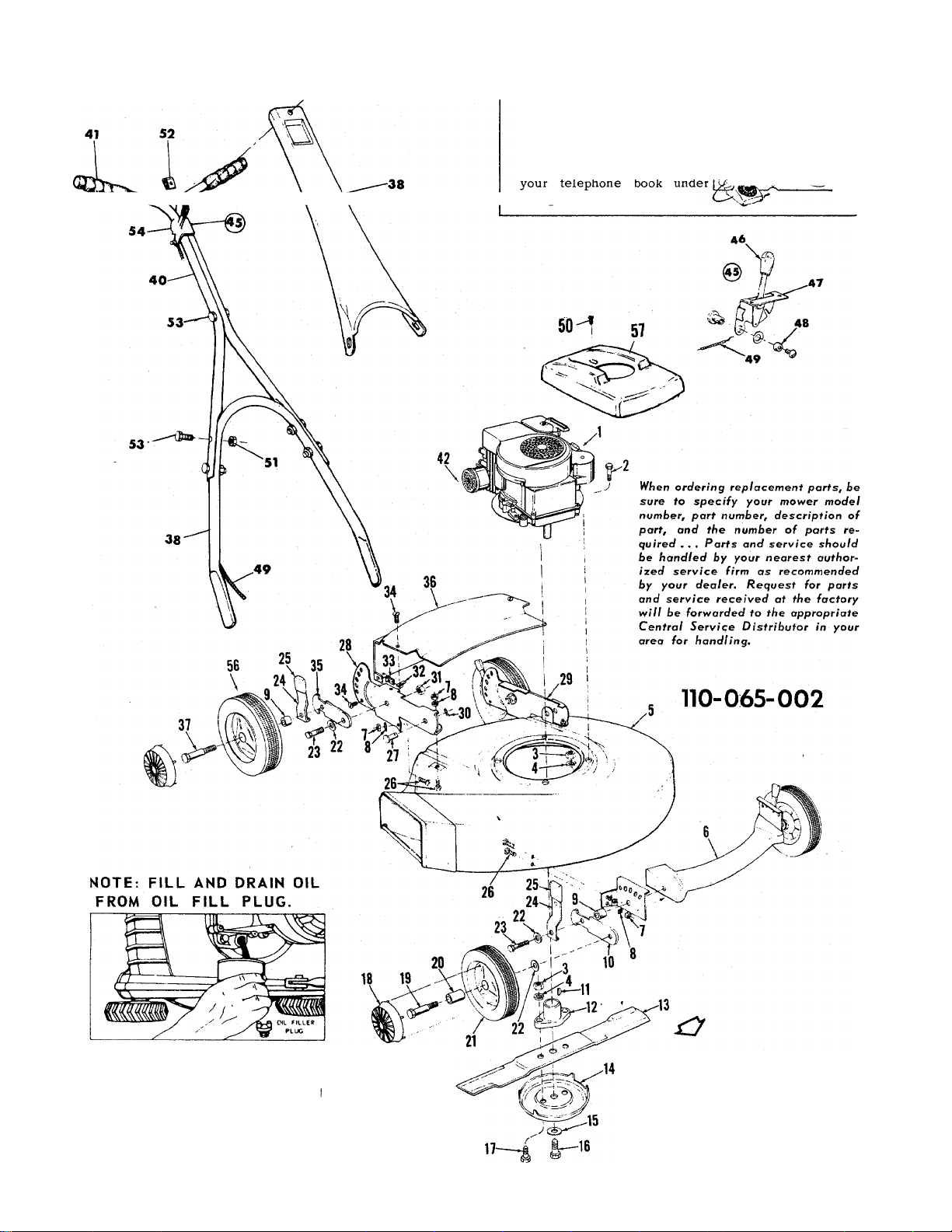
PARTS LIST FOR MOWER MODEL 110-065-002
Ref.
No.
1
2 710-158
3
4 736-119
5
6
7
8 736-498
9
10
11
12
13
14 312-7919
15 736-169
16 710-113
17
18 310-8494
19 738-102
20 305-7006
21
22 736-105
23 710-191
24 310-9008
Part
No.
—
Engine
Hex Head Cap Screw 5/16- 24 x 1-1/4 Lg. *
712-123
Hex Nut 5/16 — 24 thread *
Spring Lockwasher 5/16 Screw *
387-9650 Deck Assembly
387-9790
712-107
Front Extension Bracket Assembly
Hex Nut 1/4 — 20 thread *
Internal Lockwasher 1/4 Screw *
711-242
310-7492
714-365
748-100
312-7582
Spacer
\^eel Pivot Bar — Front
Key - Hi Pro #505
Blade Adapter
Blade
Anti-Scalp Plate
Spring Lockwasher 3/8 Screw *
Hex Head Cap Screw 3/8-24 x 1-5/8 Lg. — Heat Treated
710-117
Hex Head Cap Screw 5/16—24 x 1 Lg. — Heat Treated
Hub Cap
Axle Bolt - Front Wheel
Fortiflex Bearing
502-9392 Wheel Assembly — Front
Belleville Washer
Hex Head Cap Screw 3/8—24 x 1-1/4 Lg. *
Spring Lever Assembly
DESCRIPTION
25 305-7520 IGiob
26 710-289 Hex Head Cap Screw 1/4—20 X 1/2 Lg. *
27
710-233 Weld Pin
28 394-9664 Rear Wheel Bracket — Right Hand
29
30
394-9665
714-104
31 712-214
32 712-207
33 712-208
34 710-192
35
310-9668 Wheel Pivot Bar — Rear
36 394-9675
37
738-213
38 310-8398
39
40
387-7857
310-9364
Rear Wheel Bracket — Left Hand
Hairpin - Cotter *
Gripco Locknut 3/8 — 24 tliread *
Speed Nut
Speed Nut
Truss Head Machine Screw 10—24 x 3/8 Lg. *
Rear Cover
Axle Bolt - Rear Wheel
Handle Lower
Handle Panel
Handle Upper
41 305-7071 Handle Grip
42
43
45 310-8511
46 305-7470
47 310-8506
310-9278
710-315
Exhaust Deflector
Hex Head Thread Cutting Screw Type “F” #8 x 5/8 Lg. *
Throttle Control Complete
Knob
Throttle Control Bracket t
48 901-7627 Ferrule Assembly t
49 732-141 Conduit and Wire t
50
710-407 Slot Hex Head Ex. Screw #8—32 x 1/2 Lg.
51 712-107 Hex Centerlock Nut 1/4-20 thread *
52
712-526 Speed Nut
53 710-106 Hex Head Cap Screw 1/4-20 x 1-1/4 Lg. *
54
55 746-145
710-606
Hex Head Cap Screw 1/4-20 x 1-1/2 Lg. *
Cable Clip (not shown)
56 501-9392 Wheel Assembly — Rear
57 387-9961 Engine Shroud
58 710-138 Round Head Machine Screw 10—24 x 1/4 Lg.
* For faster service order standard nuts, bolts, and washers locally. If these items cannot be obtained locally,
order by part number and size as shown on parts list.
t Part of Throttle Control Complete 310-8511
FORM NO. 770-2796 C
Page 4

HANDLE ASSEMBLY
Your new mower is shipped preassembled with the ex
ception of the handle and throttle control assembly.
1. Remove lawn mower and all parts from carton. Make
certain that all loose parts and literature are removed
from carton before carton is discarded.
2. Extend throttle control assembly, which is attached to
engine at rear of mower, and place on floor. CAUTION:
Do not bend or kink control wire.
3. A. Snap lower handle into position on two lugs which
extend from either side on rear of the deck.
B. Assemble the t\yo upper handle parts with cap screw
iii lower holes. Place speed nut on control. Position
control over upper handle assembly with speed nut
to top. Line up control mounting holes with top
holes in upper handle and secure with cap screw
(yellow) and locknut. Do not tighten.
C. Attach upper handle to lower handle with cap screws
in lower holes only. Do not tighten.
D. Fasten control panel to upper handle with cap
screws in lower holes and round head machine
screw through upper hole. Tighten all nuts.
E. Secure control wires to lower handle with cable clips.
OPERATION
NOTE: For shipping purposes your mower is set with the
wheels in a low cutting height position. For best results,
raise the cutting position until it is determined which height
is best for your lawn. See Adjustments.
1. Service engine with gas and oil. See Engine Manual packed
with lawn mower for complete instructions for the care
maintenance of engine. READ DIRECTIONS CARE
FULLY.
2. When ready to start engine, place throttle control lever in
“START” position and start engine in accordance with
instructions in Engine Manual. After engine starts, move
throttle control lever to desired engine speed. The engine
is stopped by placing control lever in the “STOP” po
sition.
3. Be sure that lawn is clear of stones, sticks, wire or other
objects which could damage lawn mower or engine. For
best results and to insure more even grass distribution, do
not mow when lawn is excessively wet.
4. Check blade bolts for proper tightness.
ADJUSTMENTS
CAUTION: Do not at any time make any adjustment to
lawn mower without first stopping engine and disconnecting
spark plug wire.
CUTTING HEIGHT — An adjusting plate and thumb lever
at each wheel position provides cutting height adjustment.
Each adjusting plate has five holes. Height of cut will be
changed when the thumb lever is moved from one hole to
another. Simply depress thumb lever towards wheel and
move wheel and lever assembly to desired position. Cutting
height will be raised as lever is moved toward front and
lowered as lever is moved toward rear. All wheels must be
positioned in relative height of cut positions.
THROTTLE — If adjustment becomes necessary, the throt
tle control wire assembly can be reset as follows:
1. Loosen, but do not remove, screw securing throttle con
trol wire assembly at engine.
2. Move throttle control lever on handle to “FAST” pos
tion.
3. Move lever, to which control wire is fastened at engine,
to full open position and retighten screw to secure
throttle control wire assembly.
LUBRICATION
IMPORTANT: Always stop engine and disconnect spark
plug wire before cleaning, lubricating or doing any kind of
work on lawn mower.
WHEELS: Wheel bearings are of lifetime Fortiflex. They
require no lubrication.
THROTTLE: Periodically lubricate throttle control lever
and throttle wire assembly with a few drops of light oil
(S.A.E. No. 10 or 20) for ease of operation.
ENGINE: Follow Engine Manual for lubrication instructions.
MAINTENANCE
CUTTING BLADE — The blade may easily be removed for
grinding or replacement as follows:
1. Remove bolt and lock washer holding blade and hub as
sembly to engine crankshaft.
2. Remove blade and hub assembly from engine crankshaft.
3. Remove two bolts, lock washers and nuts holding blade
to blade hub.
When sharpening blade, follow the original angle of grind as
a guide. It is extremely important that each cutting edge
receives an equal amount of grinding to prevent an un
balanced blade. An unbalanced blade will cause excessive
vibration when rotating at high speeds and may cause
damage to the mower.
Upon reassembly, make certain all parts are assembled
properly and tightened securely.
DECK - The underside of mower deck should be cleaned
after each period of use as grass clippings, leaves, dirt and
other matter will accumulate. This accumulation of grass
clippings, etc. is undersirable as it will jnvite corrosion
and may cause an uneven discharge of grass clippings
at the next cutting.
The deck may be cleaned by tilting the mower forward or
on its left side and scraping clean with a suitable tool or by
washing with a stream of water from a garden hose.
CAUTION : Do not direct the stream of water at a hot en
gine as damage to the engine may result.
STORAGE — The following steps should be taken to prepare
lawn mower for storage.
1. Clean and lubricate mower thoroughly as described in the
preceding instructions.
2. Refer to Engine Manual for correct engine storage in
structions.
3. Coat mower’s blade with chassis grease to prevent rusting.
4. Place blocks under deck to raise tires clear of floor.
5. Store mower in a dry, clean area.
USING YOUR MOWER
For best results, do not cut wet grass because it tends to
stick to underside of the mower thus preventing proper dis
charge of grass clippings. If wet grass must be cut, reduce
engine speed and walking speed to help distribute the clip
pings more effectively.
New grass should be treated as wet grass, otherwise a nor
mal walking speed is about the right pace for efficient
mowing. . . The best mowing pattern is one that allows the
clippings to discharge towards the uncut part of the lawn.
This permits recutting of the clippings to further pulverize
them. When cutting high weeds, discharge towards cut por
tion, then recut at right angles to first direction.
Lawn should be cut in the fall as long as there is growth.
FORM NO. 770-2796 D
PRINTED IN U.S.A.
 Loading...