

Page 1
OWNER'S GUIDE
ASSEMBLY • OPERATION • MAINTENANCE • PARTS
$1.00
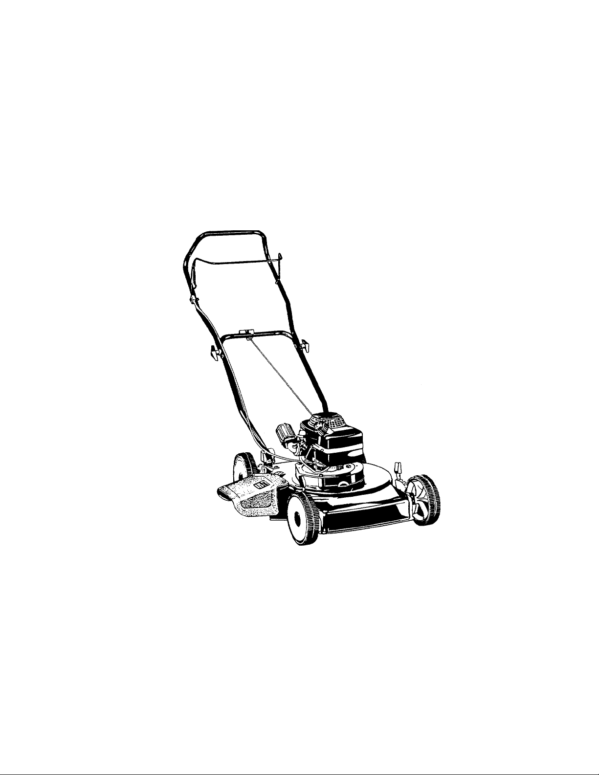
16"
Model Number
ROTARY
110-017R000
MOWER
Important: Read Safety Rules and Instructions Carefully
PRINTED IN U.S.A.
FORM NO. 770-7247E
Page 2

INDEX
Slope Gauge
Contents of Hardware Pack
Safety Rules...................................................................5
Assembly........................................................................6
Operation........................................................................7
Maintenance...................................................................9
Service and Adjustments
Storage
Service Recommendations
Trouble Shooting..........................................................13
Replacement Parts
Parts Information
The use of any accessory on this Rotary Mcwer other than those manufactured by the mower manufacturer
is not recommended.
A
..................................................................
...........................................
.............................................
........................................................................
..........................................
..............................................
..........................................
WARNING: To reduce the risk of injury, do not operate mower unless rear trailing shield and guard are in their proper places.
Back Cover
3
4
10
11
12
14, 15
Dear Customer,
So often throughout the year we are all in a
rush to meet our daily obligations.
However, we at MTD Products Inc are tak
ing a quick moment out to say...
“Thank you for your business.”
Sincerely,
MTD PRODUCTS INC
INSTRUCTIONS GIVEN WITH THIS SYM
BOL ARE FOR PERSONAL SAFETY. BE
A
SURE TO FOLLOW THEM.
WARNING: This unit is equipped with an internal combustion engine and should not be used on or near any unim
proved forest-covered, brush-covered or grass-covered land unless the engine’s exhaust system is equipped with
a spark arrester meeting applicable local or state laws (if any). If a spark arrester is used, it should be maintained
in effective working order by the operator.
In the State of California the above is required by law (Section 4442 of the California Public Resources Code).
Other states may have similar laws. Federal la\i/s apply on federal lands. A spark arrester for the muffler is available
through your nearest engine authorized serv ce dealer.
Page 3

---------
/
------------------------------------------------------------------------------------
cut Aior Line---------------------------------------------------------------------------------------- ^ —-
USE THIS SHEET AS A GUIDE TO DETERMINE SLOPES WHERE YOU MAY NOT OPERATE SAFELY.
SIGHT AND HOLD THIS LEVEL WITH A VERTICAL TREE
----------------
^
--------------------------------
..................
w
A POWER POLE
A CORNER OF A BUILDING
..
OR A FENCE POST
WARNING
7;
(D
O
•D
in
(n
3T
o
o
5‘
0)
0>
D>
(D
■D
0)
O
<D
O
■i4i
c
f¥
c
<D
•T
<D
<D
-t
O
3
o
<b
CO
"D
O
O
Ac
Do not mow on inclines with a slope in excess of 15 degrees (a rise of approximately 2V2 feet every 10 feet). A
riding mower could overturn and cause serious injury. If operating a walk-behind mower on such a slope, it is
extremely difficult to maintain your footing and you could slip, resulting in serious injury.
Operate RIDING mowers up and down slopes, never across the face of slopes.
Operate WALK-B^HIND mowers across the face of slopes, never up and down slopes.
Page 4
I I
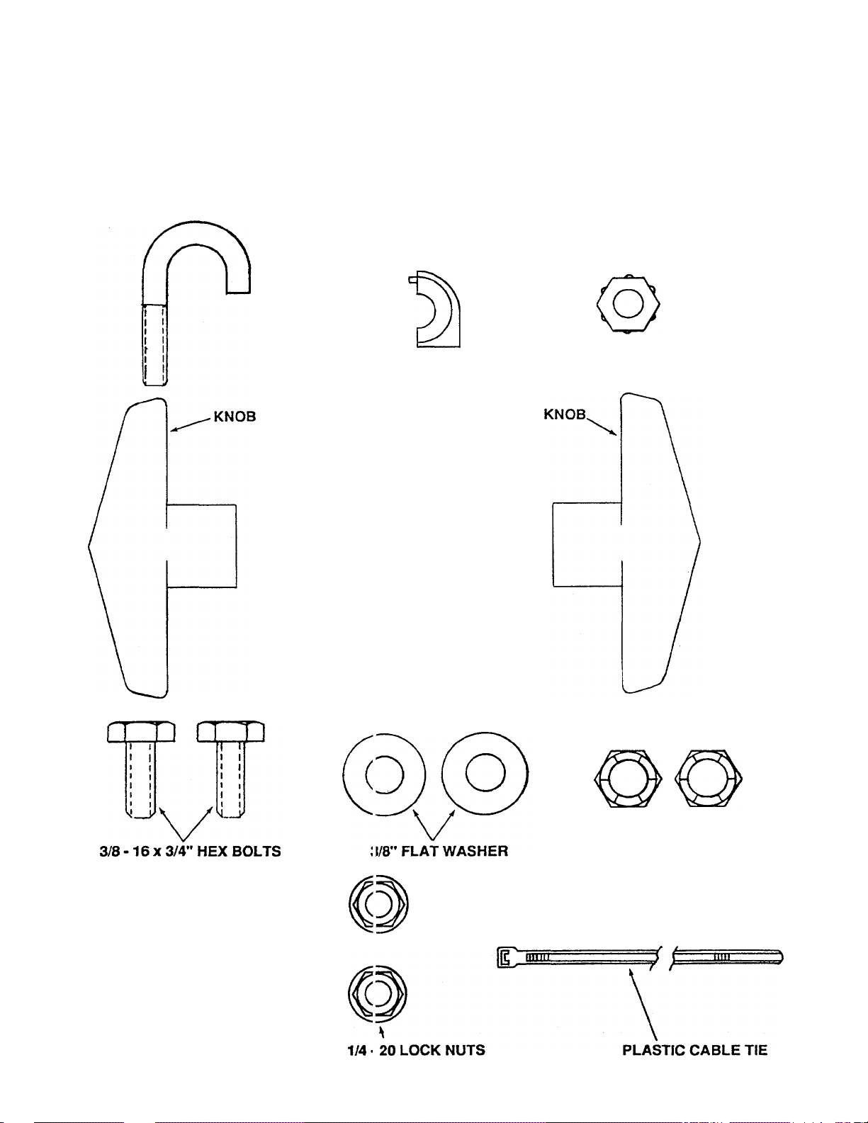
Remove this sheet from your owner’s manual and lay the hardware on the illustration for identification purposes.
After assembly, keep the Slope Gauge which is on the reverse side of this sheet for future use.
HARDWARE PACK CONTENTS
J - BOLT
I
ROPE (iUIDE HALVES 1/4 - 20 HEX NUT
/ \
1
3
CURVED WASHERS
-----
-----Tf
h
\ /
5/16 - 18 X 2" SADDLE BOLTS
V
3/8-16 LOCK NUTS
o
c
>
—I
3"
at
3
<0
(to
1/4 - 20 X 3/4" CARRIAGE BOLTS
Page 5

SAFETY RULES
CAUTION: ALWAYS DISCONNECTSPARK PLUG WIREAND PLACE WIRE WHERE IT CANNOT
CONTACT SPARK PLUG TO PREVENT ACCIDENTAL STARTING WHEN SETTING-UP, TRANS
A
PORTING, ADJUSTING OR MAKING REPAIRS TO YOUR MOWER.
A
IMPORTANT
FEDERAL REGULATIONS REQUIRE OPERATOR PRESENCE BLADE STOP CONTROLS TO MINIMIZE THE RISK
OF CONTACT INJURY. YOUR MOWER IS EQUIPPED WITH SUCH CONTROLS. DO NOT ATTEMPT TO DEFEAT
THE FUNCTION OF THE OPERATOR PRESENCE CONTROL UNDER ANY CIRCUMSTANCES.
TRAINING:
• Read the owner's manual carefully. Becxime familiar with
the controls and know how to operate this mower prop
erly. Learn how to stop the mower quickly.
• DO NOT allow children to use this mower. Never allow
adults to use the mower without proper instructions.
• Keep the area of operation clear of all persons, especially
small children and pets.
• Use the moweronly as the manufacturer intended and as
described in this manual.
• When not using your mower, store it indoors in a dry, high
or locked-up place - out of reach of children.
• DO NOT operate mower if it has been dropped or dam
aged in any manner. Always have damage repaired
before using the mower.
• DO NOT use accessory attachments not recommended
by the manufacturer - it may be hazardous.
PREPARATION:
• Objects struck by the lawn mower will be thrown and can
cause severe injury to persons. Always check the area to
be mowed and clear it of all stones, sticks, wires, bones,
etc.
• Dress properly - Wear only solid shoes when mowing.
Never mow when barefoot or wearing open sandals.
• Always wear safety glasses or eye shields when starting
and while using your lawn mower.
• DO NOT fill gas tank when the engine is running, indoors
or when engine is hot. Allow the engine to cool for several
minutes before filling the gas tank. Clean off any spilled
gasoline before starting the engine.
• Never make wheel height adjustments while the engine is
running.
• Mow only in daylight or good artificial light.
• DO NOT operate mower in wet grass. Always be sure of
your footing - keep a firm hold on the handles and walknever run.
OPERATION:
• DO NOT change the governor settings or overspeed the
engine.
• DO NOT put hands or feet near or under rotating parts.
Keep clear of the discharge opening at all times.
• Stop the engine whenever you leave the mower, before
crossing drives, walks or roads.
• DO NOT continue to run your mower if you hit a foreign
object. Stop the engine, make absolutely sure the blade
and all moving parts have stopped, disconnect the spark
plug wire from the spark plug to prevent accidental
starting, then inspect the mower for damage and repair
before restarting and operating the mower.
• If mower should start to vibrate heavily, stop the engine,
check for the cause and repair. Remember, heavy
vibration is generally a sign of trouble.
• Stop the engine, wait for blade and all moving parts to
stop, before cleaning, unclogging chute, removing grass
catcher, repairing or inspecting the mower. Always
disconnect the spark plug wire and keep away from plug
to prevent accidental starting.
• DO NOT run engine indoors - exhaust fumes are danger
ous.
• Never cut grass by pulling the mower towards you. Mow
grass across the face of slopes, never up and down or you
could lose your footing. DO NOT mow excessively steep
slopes. Use caution when operating the mower on
uneven terrain or when changing direction - maintain
good footing.
• Never operate the mower without proper guards, plates
or other safety devices in place.
MAINTENANCE AND STORAGE:
Check the blade and the engine mounting bolts often to
be sure they are tightened properly.
Check all bolts, nuts and screws at frequent intervals for
proper tightness to be sure mower is in safe working
condition.
Never store mower with fuel in the tank inside a building
where ignition sources are present such as hot water
heater and space heaters, clothes dryers, and the like.
Allow engine to cool before storing in any enclosure.
To reduce fire hazard, keep the engine free of grass,
leaves or excessive grease and oil.
If grass catcher is used with your mower, check it often for
deterioration and wear and replace worn bags. Use only
replacement bags that are recommended by and comply
with specifications of the manufacturer of your mower.
Keep a sharp blade on your mower.
A
LOOK FOR THIS SYMBOL TO POINT OUT IMPORTANTSAFETY PRECAUTIONS. IT MEANSATTENTION!!! BECOME ALERT!!! YOUR
SAFETY IS INVOLVED.
Page 6

ASSEMBLY
Your lawn mower has been completely assembled i it the
factory except for the handles and safety chute gu ard.
TO REMOVE MOWER FROM CARTON
• Remove loose parts if included with mower, (i.e.
handles, chute guard, hardware pack, etc.).
• Cut down corners on one end of carton and la^ end
down flat.
• Remove packing material.
• Roll mower out of carton and check carton thor
oughly for loose parts.
HOW TO SET-UP YOUR LAWN MOWER
ATTACH LOWER HANDLE (See Fig. 1)
Your mower handle can be raised or lowered for your
mowing comfort by assembling the lower handle ii i the
desired position. This must be done before yoi as
semble the upper handle.
• Lay upper handle on work surface behind mowe ■ and
position engine cable so it is on the outside of jeck
mounting bracket as shown.
• We recommend attaching the handles in the "H GH"
position. This will put the upper handle approxi
mately 37 inches up from the ground with the wt leels
adjusted in the mid-position. The "LOW" pos ition
measurement is approximately 34 inches.
• Position lower handle in desired position by turning
handle over so desired "HIGH" or "LOW" readi ig is
upwards.
• Attach loosely one leg of lower handle to handle
bracket with 3/8-16 x 3/4" hex bolt, 3/8" flat washer
and 3/8-16 lock nut as shown. Do not tighten.
NOTE: Be sure hex bolt is assembled from outside of
bracket as shown.
• Repeat assembly for opposite side of lower ha idle.
• Now tighten all bolts and nuts securely on both t ides
of lower handle.
Tighten knobs securely.
Secure engine cable to lower handle with plastic tie
(See Fig. 5).
ATTACH STARTER ROPE TO HANDLE (See Fig. 3)
Assemble starter rope to lower handle cross bar, from
eithertop or bottom side as desired, with "J" bolt, two (2)
rope guide halves and 1/4-20 hex nut. Tighten nut
securely with 7/16" wrench.
ATTACH SAFETY CHUTE GUARD (See Fig. 4)
Assemble safety chute guard to mower with two (2) each
carriage bolts and 1/4" locknuts as shown. Tighten nuts
securely with 7/16" wrench.
Position upper handle so operator presence control
bar is on top and assemble to lower handle with
saddle bolts, curved washers and knobs as shown.
A
CAUTION: DO NOT RUN YOUR LAWN MOWER
WITHOUTCHUTEGUARDORAPPROVEDGRASS
CATCHER IN PLACE.
Page 7

OPERATION
KNOW YOUR LAWN MOWER
READ THIS OWNER'S MANUAL AND SAFETY RULES BEFORE OPERATING YOUR ROTARY
MOWER. Compare the illustrations with your Rotary Mower to familiarize yourself with the location
of various controls and adjustments. Save this manual for future reference.
OPERATOR PRESENCE CONTROL BAR
MEETS CPSC SAFETY REQUIREMENTS
Our Rotary Walk-Behind Power Mowers conform to the safety standards of the American National Standards Institute, and
the U.S. Consumer Product Safety Commission. The blade turns when the engine is running.
OPERATOR PRESENCE CONTROL BAR - must be
held down to the handle to start and run the engine.
Release to stop the engine.
STARTER ROPE - used for starting the engine.
PRIMER - pumps additional fuel from the carburetor to
the cylinder for use when starting a cold engine.
Page 8

OPERATION
BEFORE USING YOUR LAWN MOWER, AGi\IN REFER TO THE “SAFETY RULES” AS SHOWN ON PAGE
5 OF THIS MANUAL. ALWAYS BE CAREFUI..
The operation of any Liiwn Mower can result in foreign objects being thrown into the eyes, which can
result in severe eye danage. Always wear safety glasses or eye shields before starting power tool
operation or while perfo rming any adjustments or repairs. We recommend wide vision safety mask for
over spectacles or stardard glasses available at your nearest distributor.
HOWTO USE YOUR MOWER
OPERATOR PRESENCE CONTROL BAR
Your mower has a control barwhich requires the op srator
to be behind the handle to start and run the mower. When
the operator releases the control bar the engine will stop
and an internal brake helps the blade to stop quickly.
When the operator leaves the operating positiDn to
remove the grass catcher, change the cutting heigh t, pick
up sticks or other objects in the way, the engine will stop
automatically when the control bar is released.
ADJUST CUTTING HEIGHT (See Flg.6)
Raise wheels for low cut and lower wheels fo'
cut.
Adjust cutting height to suit your requirements.
Medium position is best for most lawns.
To change cutting height, squeeze adjuster lever
toward wheel. Move wheel up or down to sui: your
requirements. Be sure all wheels are in the same
setting.
high
WARNING: Experience indicates that alcohol blended
fuels (called gasohol or using ethanol or methanol) can
attract moisture which leads to separation and formation
of acids during storage. Acidic gas can damage the fuel
system of an engine while in storage. To avoid engine
problems, the fuel system should be emptied before
storage for 30 days or longer. Drain the gas tank, start the
engine and let it run until the fuel lines and carburetor are
empty. Use fresh fuel next season. See Storage Instruc
tions for additional information. Never use engine or
carburetor cleaner products in the fuel tank or permanent
damage may occur.
• TO MIX OIL & GASOLINE - To assure thorough
mixing of oil and gasoline, fill an approved, clean
container with recommended gasoline to one quar
ter full. Add recommended oil per 24:1 mix ratio.
(One gallon of gasoline requires 5 ounces of oil).
• Screw cap tightly on container and shake vigorously.
Then unscrew cap and fill container with gasoline
until fu II. Once oil and gasoline are mixed they will not
separate.
• DO NOT MIX OIL AND GASOLINE DIRECTLY IN'
THE ENGINE FUELTANK. This will allow oil to enter
the carburetor which will cause engine to be inopera
tive.
BEFORE STARTING ENGINE
OIL & GAS MIXING
• Use a clean, high quality 2 cycle oil. DO NOT use
multi-viscosity oils. Such oils may not provide ade
quate lubrication and additives in the oil may cause
fouling of the spark plug resulting in difficult oi non
starting of the engine. DISREGARD THE Ml KING
INSTRUCTIONS ON THE OIL CONTAINER. Follow
the instructions below.
• Use fresh, clean, unleaded automotive gasDiine.
(Leaded gasoline and oil mix can be used). DO NOT
USE PREMIUM OR HIGH OCTANE GASOLNE.
TO START ENGINE
• Connect spark plug wire to spark plug.
• PRIME ENGINE (See Fig. 5 on page 7) A. To start a new engine, or one that has run out of
fuel, push primer 12 to 15 times to fill fuel lines and
carburetor. Use firm full pushes.
B. To start a cold engine which has been run
previously, but not emptied of fuel, push primer 1 time
using a full push.
C. To start a warm engine, priming is not usually
necessary. (If engine does not start after three pulls
of the starter, push primer 1 time using a full push).
• Hold operator presence control bar down to the
handle and pull starter handle quickly. Do not allow
starter rope to snap back.
• To "STOP" engine, release operator presence con
trol bar.
NOTE: In cooler weather it may be necessary to use 2
pushes and repeat priming steps between pulls. In
warmer weather over priming may cause flooding and
engine will not start. If you do flood engine wait a few
minutes before attempting to start and DO NOT repeat
priming steps.
Page 9

OPERATION
MOWING TIPS
• Under certain conditions, such as very tall grass, it
may be necessary to raise the height of cut to reduce
pushing effort and to keep from overloading the
engine and leaving clumps of grass clippings.
• For extremely heavy cutting, reduce the width of cut.
MAINTENANCE
CAUTION: DISCONNECT SPARK PLUG WIRE
FROM SPARK PLUG AND PLACE Wl RE WH ERE IT
A
GENERAL RECOMMENDATION
• Once a year you should replace the spark plug, air
• Follow the Service Recommendation Schedule on
CANNOT COME IN CONTACT WITH THE SPARK
PLUG BEFORE PERFORMING ANY MAINTE
NANCE OR ADJUSTMENTS.
filter, and check blade for wear. A new spark plug
and air filter assures proper air-fuel mixture and
helps your engine run better and last longer.
page 12.
Cutting in a counterclockwise direction, starting at
the outside of the area to be cut, spreads grass
dippings more evenly and puts less load on the
engine. To keep clippings off of walkways, flower
beds, etc., make the first cuts in a clockwise direc
tion.
Pores in cloth grass catchers (optional accessory)
can become filled with dirt and dust with use and
catchers wilt collect less grass. To prevent this,
regularly hose catcher off with water and let dry
before using.
• Use block of wood to hold blade and tighten bolt
clockwise. The recommended torque is 35 - 40 ft.
lbs.
NOTE: The bolt used to secure the blade to engine is
specially heat treated. Do not substitute (See Repair
Parts).
CAUTION: A LOOSE BLADE CAN BE DANGER
A
Use only an original manufacturer's replacement blade to
get the best cutting results.
OUS AND MAY MAKE THE ENGINE HARD TO
START.
MOWER
BLADE CARE
Your mower will work better with a sharp blade.
TO REMOVE BLADE (SEE FIG. 7):
• Turn mower on its side. Make sure air filter and
carburetor are up.
• Use a block of wood between blade and mower
housing to prevent blade from turning when bolt is
removed. Protect your hands with gloves and/or
wrap Wade with heavy cloth.
• Remove blade bolt by turning counterclockwise.
Use a 9/16" box or open-end wrench.
NOTE: Check the blade bolt lock washer at each
removal for damage and replace if necessary. The lock
washer should be replaced after every three (3) blade
removals to insure proper tightness.
TO REPLACE BLADE (SEE FIG. 7):
• Make sure key is in slot in crankshaft.
> Put blade adaptor on engine crankshaft.
Fit blade in adaptor. Be sure trailing edge of blade is
up towards engine.
• Assemble retainer plate, lock washer (undamaged)
and blade bolt.
NOTE: We do not recommend sharpening the blade - but
if you do, be sure blade is balanced.
TO SHARPEN BLADE:
• The blade can be sharpened with a file or on a
grinding wheel. Do not attempt to sharpen while on
the mower.
Page 10

MAINTENANCE
• Careshouldbetakentokeepthebladebalanced. An
unbalanced blade will cause excessive vib ation
when running and eventual damage to mower and
engine.
• To check blade balance, drive a nail into a beam or
wall. Leave about one inch of the straight nail
exposed. Place center hole of blade over the head
of the nail. If blade is balanced, it should rema n in a
horizontal position. If either end of the blade moves
downward, blade is not balanced. Sharpen the
heavy end until the blade is balanced.
ENGINE
SPARK PLUG
Change your spark plug each year to make your engine
start easier and run better. Set spark plug gap a .025
inch.
AIR FILTER
Your engine will not run properly and may be damaj led by
using a dirty air filter.
Replace the air filter every year, more often if you n low in
very dusty, dirty conditions. Do not wash air filter, -liters
are available at your nearest Tecumseh Dealer.
CLEANING
CAUTION: DISCONNECT SPARK PLUG WIRE
FROM SPARK PLUG AND PLACE WIRE WH ERE IT
A
• Clean your mower and engine often to keep build-up
• Turn mower on its side with carburetor up.
• Clean the underside of your mower by scraping to
NOTE: We recommend that you clean the underside of
your mower after each use. We DO NOT recommend
using a garden hose to clean mower unlessthe electrical
system, muffler, air filter and carburetor are covered to
keep water out. Water in engine can result in shortening
engine life.
CANNOT COME IN CONTACT WITH THE SPARK
PLUG.
of trash from accumulating around engine. A
clogged engine runs hotter and shortens engine life.
remove build-up of grass and trash.
SERVICE AND ADJUSTMENTS
TO ADJUST HANDLE HEIGHT
See "ATTACH LOWER HANDLE" in assembly sec (ion of
manual.
TO ADJUST CUniNG HEIGHT
See "ADJUST CUTTING HEIGHT' in operation section
of manual.
CARBURETOR
Your carburetor has a non-adjustable fixed main jet for
mixture control. If your engine does not operate properly
due to suspected carburetor problems, take your mower
to a authorized Service Center for repair and adjus tment .
ENGINE SPEED
Your engine speed has been factory set. Do not attempt
to increase engine speed or it may result in personal
injury. If you believe that the engine is running too fast or
too slow, take your mower to an authorized Service
Center for repair and adjustment.
REAR TRAIL SHIELD
The reartrail shield, attached between the rear wheels of
your mower, is provided to minimize the possibility that
objects will be thrown out the rear of the mower into the
operator mowing position.
If the shield becomes damaged, it should be replaced.
10
Page 11

STORAGE
"^our mower and engine should be prepared for off-
jeason storage as follows:
MOWER
• Clean underside of mower housing (See "CLEAN
ING" in maintenance section of manual).
• Inspect and replace/sharpen blade, if required (See
"BLADE CARE" in maintenance section of manual).
• Lubricate as shown in Service Recommendation
chart on page 12 of manual.
HANDLE (See Fig. 8)
You can fold your mower handle for storage as shown.
• Loosen the two (2) hand knobs on sides of the handle
and fold upper handle as shown.
CAUTION: When folding handle for storage or transpor
tation, be careful not bend or kink the engine control
cable.
ENGINE
Drain fuel and run engine until fuel system is empty.
IMPORTANT: IT IS IMPORTANT TO PREVENT GUM
DEPOSITS FROM FORMING IN ES
SENTIAL FUEL SYSTEM PARTS
SUCH AS CARBURETOR, FUEL FIL
TER, FUEL HOSE, OR TANK DURING
STORAGE. ALSO, EXPERIENCE
INDICATES THAT ALCOHOL
BLENDED FUELS (CALLED GASOHOL OR USING ETHANOL OR
METHANOL) CAN ATTRACT MOIS
TURE WHICH LEADS TO SEPARA
TION AND FORMATION OF ACIDS
DURING STORAGE. ACIDIC GAS
CAN DAMAGE THE FUEL SYSTEM OF
AN ENGINE WHILE IN STORAGE.
OTHER
• Do not store gasoline from one season to another.
• Replace your gasoline can if your can starts to rust.
Rust and/or dirt in your gasoline can cause prob
lems.
• Do not store your mower under any plastic cover.
Plastic cannot breathe which allows condensation to
form and cause your mower to rust.
A
CAUTION: NEVER STORE THE LAWN
MOWER WITH GASOLINE IN THE TANK
INSIDE A BUILDING WHERE FUMES MAY
REACH AN OPEN FLAME OR SPARK.
ALLOW THE ENGINE TO COOL BEFORE
STORING IN ANY ENCLOSURE.
11
Page 12

SERVICE FIECOMMENDATIONS
SERVICE RECORD
Fill in Dates as you complete regu
lar service
Blade Replaced
Blade Lock Washer Checked/
Replaced (See "BLADE CARE")
Air Cleaner Replaced
Spark Plug Replaced
Lubricate Mower
Cleaning
Grass Catcher (if applicable)
Muffler
SCHEDULE
Every
25
Hours
v/
v/
v/
v/
Every
SERVICE DATES
Use
v/
- CHECK
LUBRICATION
ENGINE
Your mower has a 2-cycle engine. The engine is II bricaled
by the oil you mix with the gasoline.
WHEEL ADJUSTERS
Use a spray lubricant on the wheel adjuster pivoi bolt.
SPRAY LUBRICANT HERE
WHEELS
DO NOT oil or grease the wheel bearings. Viscous lubri
cants will attract dust and dirt that will shorten the ife of the
self-lubricating wheel bearings. If youfeelthewhoels must
be lubricated, use only a dry, silicon type lubricant spar
ingly.
12
Page 13

TROUBLE SHOOTING POINTS
PROBLEM
Does not start 1. Dirty Air Filter.
Loss of Power
Poor cut ■ Uneven
CAUSE
Out of fuel.
2.
3. Stale fuel.
4. Spark plug wire is disconnected. 4.
5. Bad spark plug. 5.
6. Water in fuel. 6.
Improper mixture of gasoline and oil.
7.
8. Loose blade.
Operator Presence Control Bar in released
9.
position.
Operator Presence Control Bar defective.
10.
1. Cutting too much grass. 1.
2. Dirty Air Filter. 2.
Build-up of grass, leaves and trash under
3.
mower.
Worn, bent or loose blade. 1.
1.
Wheel heights uneven. 2.
2.
Build-up of grass, leaves and trash under
3.
mower.
CORRECTION
1.
Replace Air Filter
2.
Fill fuel tank.
3.
Drain fuel tank and refill with mixture
of fresh gasoline and oil.
Connect wire to spark plug.
Replace spark plug.
Drain fuel tank and refill with mixture
of fresh gasoline and oil.
7.
Drain fuel tank and refill with proper
mixture of gasoline and oil.
8.
Tighten blade bolt (Check lock washer).
9.
Depress Operator Presence Control
Bar.
10.
Replace Control Bar.
Set in "Higher Cut" position.
Replace Air Filter.
3.
Disconnect spark plug wire and clean
underside of mower housing.
Replace blade. Tighten blade bolt.
Set all wheels at same height.
3.
Disconnect spark plug wire and clean
underside of mower housing.
Too much Vibration
Starter Rope
Hard to Pull
Hard to Push
1. Worn, bent or loose blade. 1.
Bent engine crankshaft. 2.
2.
Engine brake is on when Operator
1.
Presence Control Bar is released.
2. Bent engine crankshaft. 2.
3. Blade dragging in grass. 3.
1. High grass or cutting height too low.
Rear of mower housing/blade dragging
2.
in heavy grass.
Handle height position not right for you. 3.
3.
2.
Replace blade. Tighten blade bolt.
Contact authorized Service Department.
1.
Depress Operator Presence Control
Bar to upper handle before pulling
on starter rope.
Contact authorized Service Department.
Get over low grass and/or hard surface
to start engine.
1.
Raise cutting height.
Raise cutting height.
Adjust handle height to suit.
13
Page 14

Model 017R
14
Page 15

Model 017R
PARTS LIST FOR MODEL 017R ROTARY MOWER
.EF.
NO.
1
706-13897-28
PART
NO.
CODE DESCRIPTION
N Hex Bolt 3/8-16 X 1-3/4" 30 747-0779
REF.
NO.
Lg-
2
706-14499-00-90
3 706-11872-01 N
4
710-0258
Plate Assembly 32 17098
N
Int. L-Wash. 1/4" I.D.
Hex Bolt 1/4-20 X 5/8" 34
Lg*
5
706-11785-06
6
706-13863-01
7
706-13815-01 N Housing—Brake Spring 38 706-13831-01-91 N
706-13865-02
8
N Screw #6-20 X 3/8 Tapping 36
N Contact—Brake Arm 37 706-10488 N
Spring—Brake Arm
N
9 706-13806-02 N Brake Arm & Pad 40
Assembly
10
706-15829
11
712-0430
12
706-10778-01 N
13
706-10777-01
14
706-13915
N FI-Wash. 3/8" I.D. 42
L-Nut 3/8-16 Thd. 43
Spacer Ring 44
Spacer
N
N
Wire Assembly—Brake
Arm
15
706-10005
16
712-0429 L-Nut 5/16-18 Thd. 49 738-0102
17
706-14487-00-14 N
18
706-13988
19
706-13856
20
706-16118
21
706-10004 N Key—Woodruff #6 53 720-0190
706-13807-01-05
.3
706-13813-00-08 N Blade—16" Gas 55
24
706-10110-00-05
25
736-0217 L-Wash. 3/8" I.D.
26
710-0152 Blade Bolt (Special)
27
706-13840-00-90 N
28
706-10007-20-09 N
N FI-Wash. 5/16" I.D. 48 706-15581-00-90 N
Deck Assembly—16" Steel
N Key—Square 5/32 x 1/2"
N Pulley—Brake 51
N Set Screw 5/16-18 x 3/8" 52 732-0404
N
Adapter Blade Mtg.
N Plate—Blade Retainer 56
Control—Handle
Hex Bolt 1/4-20 x 1-1/4"
Lg.
29
712-0324 L-Nut 1/4-20 Thd. 60
PART
NO.
31
706-10786
33 706-13816
706-10065-01
35
706-10072-32-09
706-10057-01
39
706-14486-01-91
706-10067-01
41
706-10007-10-09 N
706-10685-02-90
706-10684-02-90
710-0216
45 706-15491-01-90
46 731-1027
47
710-0134
50 706-15533-09 N
—
706-15533-10 N
738-0507B
54 15262B
15261A
736-0105
57
736-0356
58 712-0798
59
706-11909 N
706-10003-01
CODE
N
N
N
N
N
N
N
N
N
N
N
DESCRIPTION
J-Bolt (Rope Guide)
Rope Guide Half (2 Req’d.)
Clip—Trail Shield
Control Cable—Brake
Plastic Tie
Saddle Bolt 5/16-18 x 2"
Saddle Washer
Knob Assembly
Upper Handle
Lower Handle
Fl-Wash. 3/8" I.D.
Hex Bolt 1/4-20 x 1/2" Lg.
R.H. Handle Bracket
L.H. Handle Bracket
Hex Bolt 3/8-16 X 3/4" Lg.*
Safety Chute Guard
Safety Trail Shield
Carriage Bolt 1/4-20 x 3/4"
Hub Cap
Wheel Bolt
Front Wheel—6"
Rear Wheel—7"
Pivot Bolt—Adjuster
Lever—Adjuster
Knob—Adjuster Lever
Pivot Arm—Adjuster
Plate—Height Adjuster
Bell-Wash. 3/8" I.D. x 7/8"
O.D.
Bell-Wash. 3/8" I.D. x
1.13" O.D.
Hex Nut 3/8-16 Thd.*
Flange Lock Nut 1/4-20
Keps Nut 1/4-20
*For faster service obtain standard nuts, bolts and washers locally.
If these items cannot be obtained locally, order by part number and
size as shown on parts list.
NOTE
Specifications subject to change without notice or
obligation.
15
NOTE: The engine is not under warranty by
the mower manufacturer. . .If repairs or
service is needed on the engine, please
contact your nearest author
ized engine service outlet.
Check the “Yellow Pages” of
your telephone book under
"Engines—Gasoline.”
Find It Fast
In The
Yellow Pages
Page 16

PARTS INFORMATION
POWER EQUIPMENT PARTS AND SERVICE
Parts and service are available through the authorized service firm s listed
below. All orders should specify the model number of your urit, part
numbers, description of parts and the quantity of each part re :|uired.
BRIGGS AND STRATTON, TECUMSEH AND PEERLESS PARTS AN'
SERVICE
Briggs & Stratton, Tecumseh and Peerless parts and service should b.,
handled by your nearest authorized engine sen/ice firm. Check the yellow
pages of your telephone directory under the listing Engines—Gasoline,
Briggs & Stratton or Tecumseh Lauson.
NOTE: If any parts are found to be missing or de ective upon assembly of this unit, write to advise the factory so that
immediate replacement can be made.
ARKANSAS NORTH LITTLE ROCK
Sutton’s Lawn Mower Shop............ 5301 Roundtop Drive
CALIFORNIA PORTERVILLE
Billious ............................................. 75 North D Street
COLORADO DENVER
Spitzer Industrial Products Co. .. 6601 N.
FLORIDA JACKSONVILLE
Radco Distributors
Small Eng. Dist................................. 7995 W. 26th Court. . . 33016
ILLINOIS LYONS
Keen Edge Co
INDIANA ELKHART
Parts & Sales Inc.............................. 2101 Industrial Pkwy.
IOWA DUBUQUE
Power Lawn & Garden Equip.. . . 2551 J.F. Kennedy
MARYLAND BELTSVILLE
Center Supply Co
MASSACHUSETTS SPRINGFIELD
Morton B. Collins Co
MICHIGAN MOUNT CLEMENS
Power Equipment Dist
MINNESOTA PLYMOUTH
Hance Distributing Inc
MISSOURI EARTH CITY
Oscar Wilson Engine & Parts ... 4159 Shoreline Dr
Automotive Equip. Service
NEW YORK CARTHAGE
Gamble Dist., Inc
..........................
.......................................
..............................
.......................
....................
.............
...............
..................................
Box 368, Rt. 4
Washington St
4909 Victor St.
Box 5459 ......................... 32207
HIALEAH
8615 Ogden Ave
Box 277
6802 Industrial Dr.
#208
..................................
300 Birnie Ave.....................01107
340 Hubbard .......................48043
12795 16th Ave. North .55441
KANSAS CITY
3117 Holmes St
West End Ave.
Box 389
.................
_______
................
...........
...........................
..................
..........
...........
............................
72117
93257
80229
60534
46516
52001
20705
63045
..64109
13619
NORTH CAROLINA
Dixie Sales Company
OHIO
Stebe’s Mid-State Mower Supply
Bleckrie, Inc
National Central...............................
Burton Supply Co............................
PENNSYLVANIA
EECO Inc
Bluemont Co
Frank Roberts & Sons
Scranton Auto Ignition Co
TENNESSEE
Ace Distributors...............................
Chilton Air Cooled Engine
TEXAS
Marr Brothers, Inc
UTAH
Powered Products...........................
VIRGINIA
RBI Corp
WASHINGTON
Equip. Northwest.............................
WISCONSIN
Wisconsin Magneto Inc
PUERTO RICO
Island Distribution Center
.....................................
..........................................
.........................................
......................
....................................
....................
..............
..............
...........................
................
............
BROWNS SUMMIT
5920 Summit Ave.............27214
CARROLL
Box 366, 71 High St
CLEVELAND
7900 Lorain Ave
WADSWORTH
687 Seville Rd..................44281
YOUNGSTOWN
1301 Logan Ave.
Box 929
HARRISBURG
4021 N. 6th St
PITTSBURGH
11101 Frankstown Rd. .15235
PUNXSUTAWNEY
R.D. 2
SCRANTON
1133-35 Wyoming Ave. . 18509
KNOXVILLE
2103 Magnolia
NASHVILLE
319 4th Ave. S
DALLAS
423 E. Jefferson
SALT LAKE CITY
1661 N. Beck St
ASHLAND
101 Cedar Ridge Dr. . . .23005
SEATTLE
1410 14th Ave
MILWAUKEE
4727 N. Teutonia St. . . .53209
RAMEY
102 N. St
...........................
...................
................................
..................
..................
..................
..........................
____
...............
...............
...............
43112
44102
44501
17110
15767
37917
3721'^
7520.
84116
98122
00604
WARRAN Y PARTS AND SERVICE POLICY
The purpose of warranty is to protect the customer from defects in workmanship and materials, defects which are NOT detected at the time
of manufacture. It does not provide for the unlimited and i nrestricted replacement of parts. Use and maintenance are the responsibility of the
customer. The martufacturer cannot assume responsibility ior conditions over which it has no control. Simply put, if it’s the manufacturer’s fault,
it’s the manufacturer’s responsibility; if it’s the customer’ i fault, it’s the customer’s responsibility.
CLAIMS AGAINST THE MANUFACTURER’S WARRANTY
INCLUDES:
1. Replacement of Missing Parts on new equipment.
2. Replacement of Defective Parts within the warranty period.
3. Repair of Defects within the warranty period.
MTD PRODUCTS INC
P.O. BOX 360900
All claims MUST be substantiated with the following
information:
1. Model Number, Serial Number and/or Date Code of unit in
volved.
2. Date unit was purchased.
3. Date of Failure.
4. Nature of Failure.
CLEVELAND, OHIO 44136
(0689)
 Loading...