

Page 1
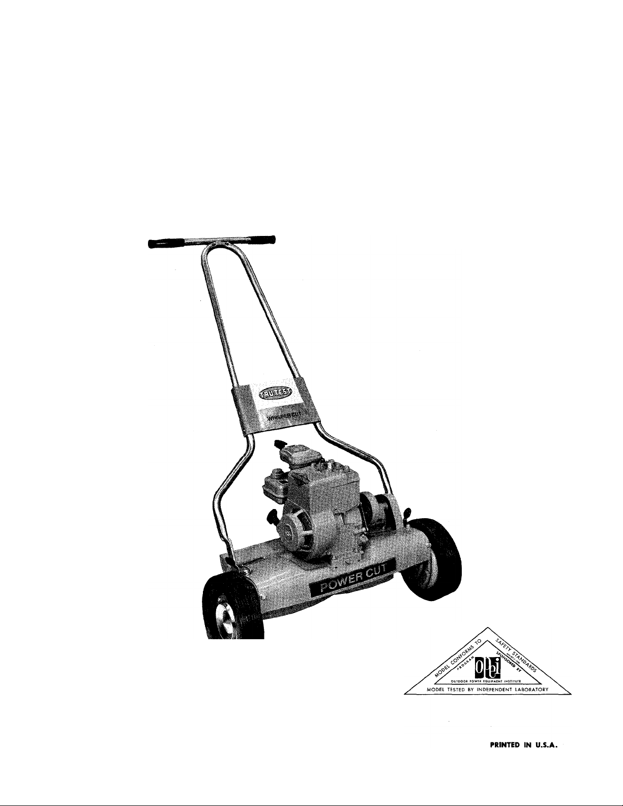
OPERATING MANUAL
and PARTS LIST
i -- 7/
MODEL 10710-0
21 INCH
REEL MOWER
0611-704
Page 2

IMPORTANT
RULES FOR SAFE OPERATION
Your Mower is a precision piece of power equipment. Engineering skill and experience have
been combined to provide the ultimate in safety and efficiency. As with any type of power
equipment, carelessness or error on the part of the operator can result in injury. Exercise
extreme caution at all times.
1.
KNOW YOUR MACHINE — Read the Owner's Manual carefully — learn how
to operate your mower properly.
2.
MAKE SURE THE LAWN IS CLEAR of sticks, stones, wire and other hazardous
items before mowing. Such items are dangerous to both the mower and
individuals in the vicinity of the mower.
3.
ADD FUEL BEFORE STARTING ENGINE—never when engine is hot or running.
4.
KEEP AREA OF OPERATION CLEAR of all persons, particularly small children
and pets.
5.
DISENGAGE ALL BLADE AND DRIVE CLUTCHES so equipped before starting
engine.
6.
ALWAYS STOP ENGINE and disconnect sparkplug wire before making cut
ting height adjustments.
7.
CHECK ALL NUTS, BOLTS, AND SCREWS occasionally to be sure mower is
in good operating condition.
8.
NEVER OPERATE EQUIPMENT IN WET GRASS. Always be sure of your
footing; keep a firm hold on the handle and walk, never run.
9.
ALWAYS CHECK FOR DAMAGE if you should strike some foreign object
with the blade while moving, stop your mower. Inspect for and repair
any damage before restarting and operating the mower.
1 0 .
STOP THE ENGINE when you leave the equipment. Make certain the blades
and all moving parts have stopped.
11.
WHEN MOWING A TERRACE, slope or incline, mow lengthwise. DO NOT
mow up or down. Be careful when turning to avoid slipping.
Page 3
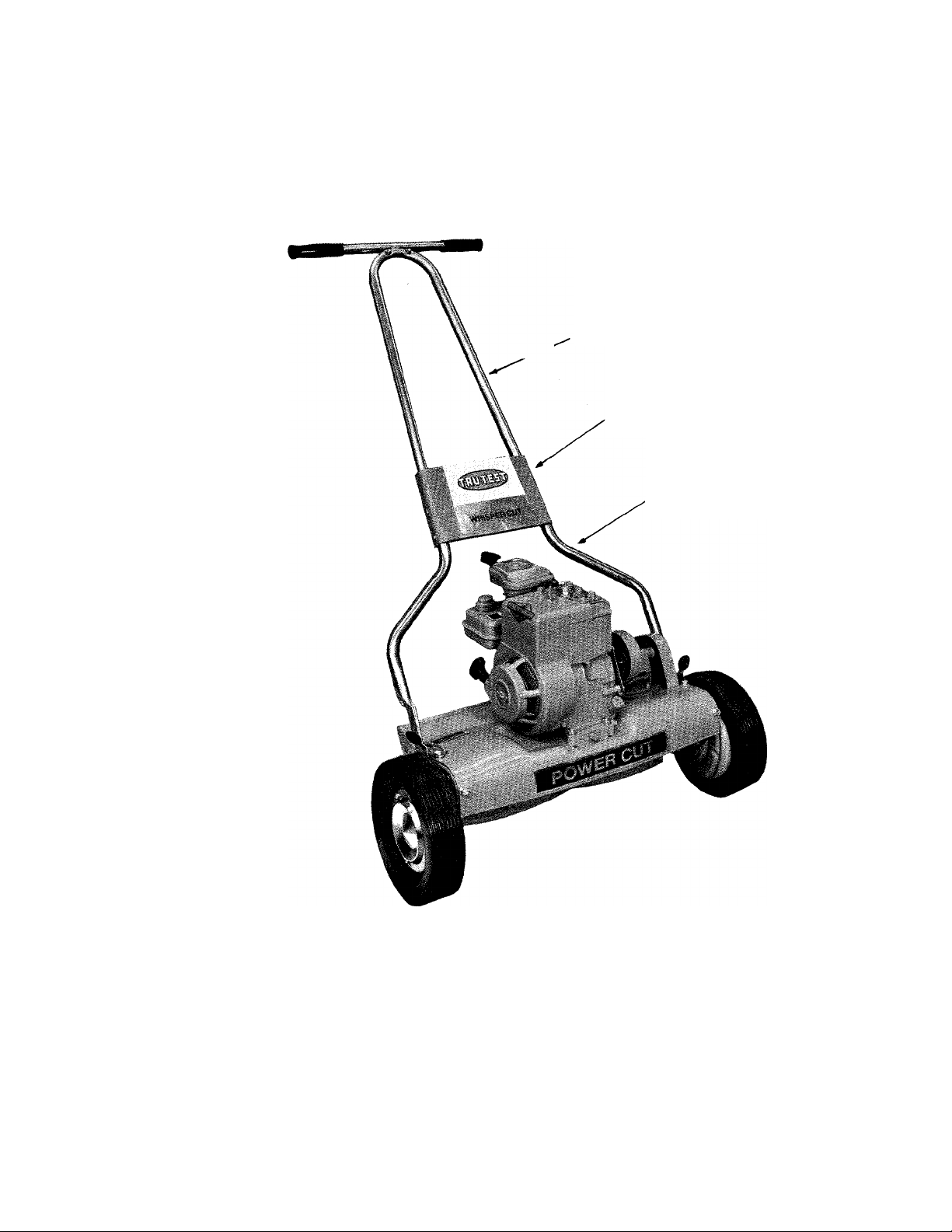
PREPARING YOUR MOWER FOR USE
UPPER HANDLE
HANDLE COVER
LOWER HANDLE
SET-UP
To assemble the handle to the chassis — place the lower handle through the opening in the left hand end plate
and slip it over the 1/2 in. dia. trunnion. While holding the stand-up handle latch open — press the right hand
side of the lower handle toward the center of the mower until it will fit into the opening in the end plate —
place handle through the opening and slip it over the 1/2 dia. trunnion.
With the lower handle section in operating position the upper handle can now be loose assembled to the lower
section with the nuts and bolts provided. Fit handle cover in place as shown and tighten bolts securely.
Page 4
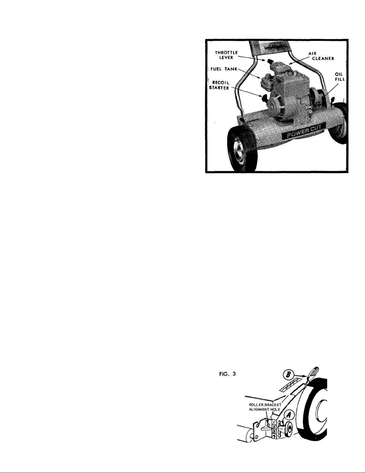
BEFORE STARTING ENGINE
1. Remove oil fill plug (Fig. 2). Place mov/er level
and fill engine crankcase to top of oil plug with
S.A.E. No. 30 oil. Tilt mower to make sure oil
flows completely into crankcase. Replace fill plug
and tighten.
2. The air cleaner protects the engine against grit
and dirt. CAUTION, an extremely dirty air cleaner
element may cause engine to stall.
SEE ENGINE INSTRUCTION MANUAL FOR PROPER
AIR CLEANER MAINTENANCE.
3. Fill tank with good grade regular, clean fresh gas
oline. DO NOT MIX OIL with gasoline.
FOR COMPLETE ENGINE INFORMATION READ ENGINE
INSTRUCTION BOOKLET FURNISHED WITH YOUR
MOWER BEFORE STARTING OR OPERATING.
TO ADJUST HEIGHT OF CUT
TO START ENGINE
1. Place handle in neutral position with handle down.
2. Set throttle control in start position.
3. Pull starter rope with a smooth, quick full stroke
once. Move throttle lever to run positipn. Pull
starter rope again.
4. When engine starts move throttle lever to an idle
position until the engine warms up.
BREAK-IN PERIOD
1. During first 10 hours of operation check frequently
the following:
* Oil level in engine crankcase.
* Belt adjustment on engine to jackshaft drive.
(Page 6)
* Check all bolts, nuts and screws for tightness.
1. Consult the chart located on Page 5, (Fig. 3A) and
Fig. 3 shown below. The roller adjusting knobs (A)
and wheel adjusting levers (B) must be in positiotrs
shown for desired cutting height. EXAMPLE: for
1 '/2" cutting height roller knob must be in No. 2
position, and wheel lever must be in No. 4 position.
(Fig. 3 and Fig. 3A)
2. Place mower on hard, flat surface and tilt machine
back on roller until wheels are off the ground. Move
right hand wheel lever outward to disengage locat
ing pin, then move lever forward or back until it is
aligned with proper number on deck label. Release
outward pressure on lever and be sure that locating
pin seats properly in hole in end plate. Repeat this
procedure on left hand side, position lever so that
mower is level.
3. Tilt mower forward until roller is off the ground.
Turn right hand roller knob counter clockwise 2 full
turns and move knob up or down until alignment
hole in roller bracket is in line with proper number
on label at rear of end plate, (see illustration)
Turn knob clockwise until tightened securely. Repeat
this procedure for other side.
OPERATING INSTRUCTIONS
TO PROPEL MOWER FORWARD, simply raise the han
dle .. . TO STOP MOWER, lower the handle.
Page 5

”f/lsr-S£r"mim
H E I G H T C O N T R O L *
ROLLER BRACKET»'
ALIGNMENT HOLE
7)1
CUTTING
HEIGHT
IN INCHES
2> /4
--- -------
2
------------
® (D
13 /4 ---- ------
1 ’/ 2
----------
iVi
------
1
-------
j/ 4----------
*Reg. T.M. Pat. opplied for.
QUALITY OF CUT
Since a reel type mower does not create a lifting action
like a rotary mower, it CANNOT lift up and cut tall
blades of grass that are bent over. If cutting height
is set too high, grass of this nature will not be in posi
tion to be drawn between the reel blades and cutter
bar and in many cases will be pushed away by the
revolving reel. Therefore, to obtain the utmost in per
formance and laWn appearance, cutting height ABOVE
W2" IS NOT RECOMMENDED except where grass is up
right and dense.
FIG. 3A
CUTTER BAR ADJUSTMENT
(Fig. 4) Cutter Bar bolts (2 & 3) are tapered and extend
beyond the side plate slightly. When these tapered
bolts are tight any end play or looseness is eliminated.
Be sure these bolts are tight before making adjust
ments.
TO TIGHTEN CUTTER BAR
Turn hex adjusting nut counterclockwise.
TO LOOSEN CUTTER BAR
Turn hex adjusting nut clockwise.
SERVICE INSTRUCTIONS
ALWAYS REMOVE SPARK PLUG WIRE BEFORE MAKING
ADJUSTMENTS
WITH ENGINE RUNNING.
Check your mower frequently to make sure all parts
are operating smoothly. Your mower left the factory
properly adjusted and properly lubricated to assure
you of a smooth clean cutting job. Keep it clean. The
mower should be thoroughly cleaned and lubricated at
the start of each mowing season for better operation
and longer service life.
DO NOT use water to clean the mower—use a broom
or brush to remove grass and dirt. When storing mow
er for any length of time, follow storage instructions in
engine instruction booklet.
CHECKING AND ADJUSTING CUTTER BAR
CLEARANCE
When properly set, the cutter bar should almost contact
the reel blades. Only on very fine grass should the reel
blades touch the cutter bar, and then very lightly so
that only a slight scraping noise is heard.
It's easy to check proper cutter bar clearance — just
place a piece of newspaper about 2" wide and 6"
long, between reel blades and cutter bar — See Step
2. Correct cutter bar clearance should pinch but not
cut, the paper at both ends and the middle of the
cutter bar. If it doesn't adjust as follows;
-------
NEVER MAKE ANY ADJUSTMENTS
REEL AND CUTTER BAR PAPER TEST
1. Insert strip of newspaper between cutter bar and
reel blades.
2. Torn reel slowly backwards. If the paper is held
snugly by each blade then adjustment is correct.
3. Adjust cutter bar so that reel blades pinch paper
without cutting it.
SERVICE
1. Sharpening is required when the mower will not
cut satisfactorily without the reel blades wiping on
the cutter bar.
SEE PAGE 12 ON HOW TO OBTAIN SERVICE AND
REPLACEMENT PARTS.
NOTE:
When cutter bar is removed for sharpening, left hand
pivot bolt (Item 2 fig. 5) must be turned counter clock
wise to be removed. Right hand pivot bolt on right
hand side of mower must be turned clock-wise.
Page 6

IMPORTANT
Your mower has been designed with a stand-up han
dle (See instructions on Pg. 7). Make sure the mower
handle is in the stand-up position before attempting
the following adujstments.
TO ADJUST CHAIN DRIVE
1. Loosen 4 engine mounting bolts and pull engine
back.
2. Loosen 4 jackshaft mounting bolts and pull jack
shaft assembly back to tighten chain. Allow Vs
inch of slack in the chain, tighten mounting bolts
and nuts securely.
3. Pull engine forward until the belt is tight then
tighten the 4 engine mounting bolts securely.
TO ADJUST RELT DRIVE
1. Check chain — if necessary adjust as described
above (To Adjust Chain Drive).
2. If the chain does not need adjusting — loosen the
4 engine mounting bolts and with the handle in
the stand-up position pull the engine forward until
the belt is tight, then retjghten the 4 engine mount
ing bolts securely.
3. Lower handle to neutral position. Disconnect spark
plug wire and fasten to the engine approx. 1-1/2
inches from the sparkplug. With a slow smooth
motion pull the starter rope a few times — watching
closely to see if the belt moves with the engine pul
ley. If the belt does move then a slight adjustment
of one or two turns (counterclockwise) of the ad
justment screw at the back of the jackshaft assem
bly must be made. CAUTION: Remember the han
dle must be in the stand-up position before making
the adjustment.
4. Repeat Step 3 if necessary until a good disengage
ment of the belt (neutral position) is obtained, then
while holding the adjustment screw — tighten the
adjustment screw locknut.
fir
JACKSHAFT ASS'Y\ ^^TG BOLTS
OPERATING^;//
POSITION
NEUTRAL
POSITION
LUBRICATION
1. Change engine oil (crankcase) after first 5 hours of
operating. See engine operating instructions.
2. Check air cleaner frequently.
3. Reel bearings require no attention until mower is
serviced.
4. Check jockshaft oiler cup frequently, oil at begin
ning or mowing season and as needed. Oil roller
shaft once or twice a year or as needed.
5. Lightly lubricate with engine oil, points indicated
on roller and between end plates and wheel dust
covers. Periodic lubrication at these points, will
insure smooth mechanical operation.(Fig. 8)
Page 7

STAND-UP HANDLE
1. There's no storage problemi with the stand-up
handle.
2. Move handle latch on the end plate in and move
handle to upright position. To transport mower in
car, remove handle from chassis for more conven
ient handling. CAUTION^ Always remove spark
plug wire before attempting to lift the mower.
STORAGE
Store your mower in a clean, dry place and keep clean
to serve you well. If stored for a length of time, the en
gine should be drained of fuel. This will prevent the
forming of gum deposits on essential parts in the car
buretor fuel line and tank, which might affect the effi
cient operation of your engine when again used.
»N
DATE
DESCRIPTION
Page 8

ALL UN-NUMBERED PARTS
INTER-CHANGEABLE WITH
OPPOSITE SIDE.
Page 9

PARTS LIST
MODEL 10710-0
When ordering parts listed as L.H. or R.H.—determine the left or right
hand side of your mower by standing behind the unit as you mow.
Do not use Reference Numbers when ordering Repair Parts, always use Part Numbers.
REF.
NO. PART NO.
1511-18
1
2 1540-59
1112-19-69
3
4
1530-6
2135-21-69
5
1548-5
6
7 2121-2-69
8 1530-20
9 1629-28
10 104
11 106
12 3
2674-26
13
1509-86
14
15 142
16 141
17 1108-95-40
1110-30-40
18
2619-34
19
1652-52
20
425
21
22 109
23 323
24
1118-9-69
1631-26
25
1540-55
26
1629-41
27
1657-19
28
2643-18
29
41-028
30
NAME OF PART
Screw (10-32 X % Phillips)
Washer—Roller
Spacer Tube Assembly —
* Rivet (3/16 X %)
Reel Assembly
Rollpin
Sprocket, Anti-Wind Cup &
Hub Ass'y
*Rivet (3/16 X 13/32)
Retainer
Felt Washer
Felt Retainer
Bearing
Hub Cap______________________
Screw Cutter Bar L. H. Thd.
*Cotter Pin (Vs X %)
Washer
Wheel and Tire Assembly
Drive Wheel & Bearings Less Tire
Tire ______________________________
Bearing___________________________
Pinion Gear—L.H.
Felt Washer
Pawl _____________________________
Gear Housing—L.H.
Axle
_____________________________
Washer
Retainer
Bushing
Knob-Wheel Adjust
Nut ______________________________
______________
_____________
______________
____________________
__________________
_____________
_____________________
___________________
------------------------------
______________________
_____________
______________________
____________
-------------------------------
---------------------------------------
----------------------------
__________________________
_________________________
__________________________
-----------------------------
REF.
NO. PART NO.
31 1117
1129-207-69
32
33 1723-1
1129-208-69
34
1624-138
35
1118-8-55
36
1657-23
37
38 428
1539-31
39
40 1156-6
1513-40
41
42
453
455
43
3134-23-69
44
1622-50
45
1643-23
46
2132-44-69
47
1529-25
48
49 1548-7
1632-58
50
1645-37
51
52 2658-13
2132-45-69
53
1540-43
54
1650-21
55
1509-38
56
1155-14
57
1616-119
58
59 1534-8
2624-112-69
60
NAME OF PART
*Screw (10-32 X % Sems)------------------------
End Plate with Trunnions—L.H. _—
Scraper ----------------------------------------------
End Plate with Trunnions—R.H. ___
Spacer
_______
Gear Housing—R.H. ------------------------------
Nylon Bushing -------------------------------------
Pinion Gear—R.H.
Trunnion
Bolt ________________________
Screw _____________
Screw Cutter Bar—R.H. Thd.
Cutter Bar Assembly __ _ ^
Dust Cover
Roller Adjust Knob
Roller Bracket Assembly—L.H. —
*Bolt (5/16-18 X %)
Rollpin
----------------------Roller Shaft
Trunnion _ Roller
_____________________________
Roller Bracket Assembly—R.H. ^—
Washer—Special
Retaining Ring
*Screw (#10-32- X % Hex Hd.) —
Spring & Trunnion Assembly
Roller Adjust Label
*Nut (10-32 Gripco)
Spacer—End Plate _
-
-------------------------------
-----------------------------
___________ _________
___
____
___________
-------------------
--------- -------------------------------
-------------- -----------
___________________
-----------------------
________________________
_____________ -...................
----------------------------------
-----------
-------------------------
-------------------
__________________
___________________
------------- -----------
.......
____
___
—
-
-
*Standard Hardware Item—Purchase Locally.
Page 10

Page 11

PRICE LIST
MODEL 10710-0
When ordering parts listed as L.H. or R.H.—determine the left or right
hand side of your mower by standing behind the unit as you mow.
Do not use Reference Numbers when ordering Repair Parts, always use Part Numbers.
REF.
PART NO.
NO.
1
2 70
3 1025
1529-11
4
5 1724-8
1509-69
6
1651-20
7
1508-13
8
9 1626-40-69
10 1548-11
2120-34-69
11
1540-17
12
1511-9
13
1540-55
14
3639-51-69
15
2102-144-69
16
3601-122-69
17
1652-1
18
19 1691-2
20 1632-26
1546-2
21
1654-2
22
1638-16
23
1036
24
1538-16
25
1113-13
26
1650-10
27
1547-3
28
29 1624-122
1642-82-69
30
2609-322-69
31
2624-164
32
1511-36
33
1616-114
34
1650-37
35
2610-14
36
2705-25-69
37
NAME OF PART
Engine—Briggs & Stratton
Model 60102-Type 0136-01
*Nut (5/16-18 Hex)
*Lock Washer (5/16) —
*Bolt (5/16-18 X 1% Carriage)
Keeper—Belt Upper — ----------------------------
*Screw (14-20 x 1% Fillister Hd.) —
"V" Belt (4L X 18")
*Set Screw (5/16-24 x 7/32)
Pulley
_________________ __________
Rollpin -------------
Pulley Assembly —_
*Washer (% x 15/16)
Screw (10-32 x ’/2 Sems) ------------------------Washer ____________________________
Belt Guard . _ - — — — -
Jackshaft Housing, Bearings
& Oiler Assembly
Jackshaft Housing
Bearing
_____
Oiler
________
Jackshaft
Pin
______:_____________
Chain
____ ___
Sprocket
Washer
_________ __________________
Nut (7/16-20 Hex Jam)
Connector Link
Retaining Ring ______________________
Pin________________________________
Spacer
___
Spring
-----------
Bracket—Striker
Spacer—Adjust --------Screw—Adjust
Label—Wheel Adjust
Retaining Ring ______________________
Adaptor .
Lever—Throttle Control
____________________
-------------------- -------
......................
_____________
---------------------
------
---------------------------
-----------------------------
------------------------------
_________________
.............. ....
—
--------------------
-
------------------------------
------------------------- -----------------
____________________
______ -------------------- -----------
------------
_____________________
_________________________
------
-----------------------------
_____________________
--------- ----------------
-------------------—---------
-----------------------------
_______ ___
— —
--------------- ---------
___
............
— —
___
_______
-----
--------
--------
----------------
REF.
NO. PART NO.
2643-41
38
1652-12
39
1534-8
40
1650-36
41
1625-24
42
1616-280
43
67
44
1018
-
- -
-
-
45
2616-493
46
3609-82-69
47
41-028
48
1513-18
49
1513-41
50
2705-26
51
52 3639-48-69
1513-8
53
117
54
55 1020
1605-563
56
57 1545-23
1547-4
58
2627-21
59
2642-51
60
1097
61
5690-10-69
62
1529-15
63
4117-95-01
64
3712-18-01
65
1509-22
66
3622-126-69
67
1538-8
68
1710-8
69
2616-492
70
1624-69
71
1724-10
72
1606-48
73
1616-449
74
1616-441
75
1616-442
76
NAME OF PART
Knob—Throttle Control
Wave Washer
*Nut (10-32 Hex Lock)
Retaining Ring
Link—Throttle Control ----------------------- —
Label—Throttle Control
*Nut (’/4-20 Hex)
*Lockwasher (’/4) ------------------------------ -
Label—Deck
Bracket
*Nut (5/16-24 Hex Lock Gripco) —
Bolt (5/16-24 Hex Shoulder Bolt) -
Bolt (5/16-24 X ¥4 Hex Hd.)
Lever — __________________________ -
Guard......................... —
*Bolt (5/16-24 X '/2 Hex Hd.)
*Screw (10-32 X % Phillips Hd.) —
*Screw (6 X V4 Rd. Hd.) _
Name Plate Clevis Pin
Cotter Pin
Latch
Spring - -------------- -------------------------- —
*Washer (3/16)
Deck
Bolt ('/4-10 X %)
Handle—Upper Section _ ----------------- -
Handle—Lower
Bolt (’/4-20 X 1% Hex Hd.)
Cover—Handle
Nut (14-20 Hex Lock)
Grip—Handle
Label—Handle Cover
Spacer
Lower Belt Keeper
Belt Keeper Bracket
Label—(Neutral-Caution)
Label—(Drive-Neutral)
Label—Lower Handle
____________________
----
________________ _________
--------------- ----------------------
______
______
------ ----------
---------
-----
_____________ ______
--------- ----- -------------------------------
--------------------------
_________________
---------------------------------
---------------------
______________________
---------------
-
-
-
--------------------------------------
-----------------------------------
_____________________
_______________ ______
______________________
--------------------
____________
-------------_____________
-----------------------
--------- ---------------
--------------------------
-----------------------------
_____________
________________
_________________
-------------- --------------
-------------------------
------------------------
---------------------------
-----------------------
----------
—
-
—
-
-
.
—
*Standard Hardware Item—Purchase Locally.
n
 Loading...