

MSI MS-7222, PM8PM-IL, PM8PM-L, PM8PM-V, MS-7222-020 - PM8PM-L Motherboard - Micro ATX User Manual
...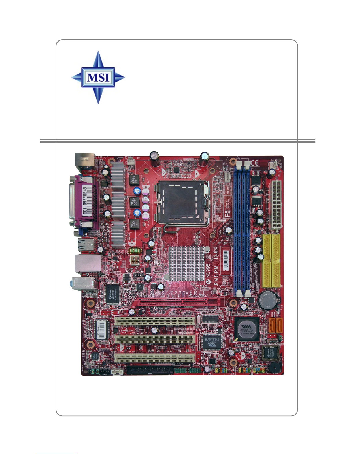
PM8PM
MS-7222 (v1.X) Micro-ATX Mainboard
G52-72221X1
i
FCC-B Radio Frequency Interference Statement
This equipment has been tested
and found to comply with the limits
for a class B digital device,
pursuant to part 15 of the FCC
rules. These limits are designed
to provide reasonable protection against harmful interference in a residential installation.
This equipment generates, uses and can radiate radio frequency energy and, if not
installed and used in accordance with the instruction manual, may cause harmful
interference to radio communications. However, there is no guarantee that interference
will not occur in a particular installation. If this equipment does cause harmful
interference to radio or television reception, which can be determined by turning the
equipment off and on, the user is encouraged to try to correct the interference by one
or more of the measures listed below.
=Reorient or relocate the receiving antenna.
=Increase the separation between the equipment and receiver.
=Connect the equipment into an outlet on a circuit different from that to which the
receiver is connected.
=Consult the dealer or an experienced radio/television technician for help.
Notice 1
The changes or modifications not expressly approved by the party responsible for
compliance could void the user’s authority to operate the equipment.
Notice 2
Shielded interface cables and A.C. power cord, if any, must be used in order to
comply with the emission limits.
VOIR LA NOTICE D’INSTALLATION AVANT DE RACCORDER AU RESEAU.
Micro-Star International
MS-7222
This device complies with Part 15 of the FCC Rules. Operation is subject to the
following two conditions:
(1) this device may not cause harmful interference, and
(2) this device must accept any interference received, including interference that
may cause undesired operation
ii

Copyright Notice
The material in this document is the intellectual property of MICRO-STAR
INTERNATIONAL. We take every care in the preparation of this document, but no
guarantee is given as to the correctness of its contents. Our products are under
continual improvement and we reserve the right to make changes without notice.
Trademarks
All trademarks are the properties of their respective owners.
AMD, Athlon™, Athlon™ XP, Thoroughbred™, and Duron™ are registered
trademarks of AMD Corporation.
Intel® and Pentium® are registered trademarks of Intel Corporation.
PS/2 and OS®/2 are registered trademarks of International Business Machines
Corporation.
Microsoft is a registered trademark of Microsoft Corporation. Windows® 98/2000/NT/
XP are registered trademarks of Microsoft Corporation.
NVIDIA, the NVIDIA logo, DualNet, and nForce are registered trademarks or trademarks of NVIDIA Corporation in the United States and/or other countries.
Netware® is a registered trademark of Novell, Inc.
Award® is a registered trademark of Phoenix Technologies Ltd.
AMI® is a registered trademark of American Megatrends Inc.
Kensington and MicroSaver are registered trademarks of the Kensington Technology
Group.
PCMCIA and CardBus are registered trademarks of the Personal Computer Memory
Card International Association.
Revision History
Revision Revision History Date
V1.0 First release for PCB 1.X DEC. 2005
with VIAP4M800 Pro & VIA8237R Plus
V1.1 Add Chapter5 for RAID Introduction APR. 2006
iii
Technical Support
If a problem arises with your system and no solution can be obtained from the user’s
manual, please contact your place of purchase or local distributor. Alternatively,
please try the following help resources for further guidance.
† Visit the MSI homepage & FAQ site for technical guide, BIOS updates, driver
updates, and other information: http://www.msi.com.tw & http://www.msi.
com.tw/program/service/faq/faq/esc_faq_list.php
† Contact our technical staff at: support@msi.com.tw
Safety Instructions
1. Always read the safety instructions carefully.
2. Keep this User’s Manual for future reference.
3. Keep this equipment away from humidity.
4. Lay this equipment on a reliable flat surface before setting it up.
5. The openings on the enclosure are for air convection hence protects the equipment from overheating. Do not cover the openings.
6. Make sure the voltage of the power source and adjust properly 110/220V before connecting the equipment to the power inlet.
7. Place the power cord such a way that people can not step on it. Do not place
anything over the power cord.
8. Always Unplug the Power Cord before inserting any add-on card or module.
9. All cautions and warnings on the equipment should be noted.
10.Never pour any liquid into the opening that could damage or cause electrical
shock.
11. If any of the following situations arises, get the equipment checked by a service
personnel:
† The power cord or plug is damaged.
† Liquid has penetrated into the equipment.
† The equipment has been exposed to moisture.
† The equipment has not work well or you can not get it work according to
User’s Manual.
† The equipment has dropped and damaged.
† The equipment has obvious sign of breakage.
12. Do not leave this equipment in an environment unconditioned, storage
temperature above 600 C (1400F), it may damage the equipment.
CAUTION: Danger of explosion if battery is incorrectly replaced.
Replace only with the same or equivalent type recommended by the
manufacturer.
iv
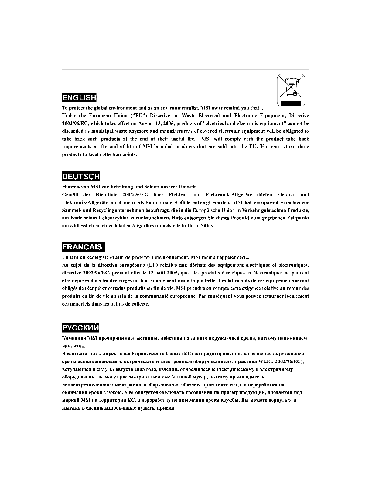
WEEE Statement
v
vi
vii

CONTENTS
Chapter 1. Getting Started...............................................................................1-1
Mainboard Specifications...............................................................................1-2
Mainboard Layout...........................................................................................1-4
Packing Contents............................................................................................1-5
MSI Special Feature........................................................................................1-6
Chapter 2. Hardware Setup..............................................................................2-1
Quick Components Guide...............................................................................2-2
Central Processing Unit: CPU.........................................................................2-3
Introduction to LGA 775 CPU..................................................................2-3
CPU & Cooler Installation.........................................................................2-4
Memory...........................................................................................................2-7
Introduction to DDR2 SDRAM..................................................................2-7
Installing DDR2 Modules..........................................................................2-7
Power Supply.................................................................................................2-8
ATX 24-Pin Power Connector: CONN1...................................................2-8
ATX 12V Power Connector: JPW2.........................................................2-8
Back Panel......................................................................................................2-9
Mouse/Keyboard Connector...................................................................2-9
VGA Connector.......................................................................................2-9
Serial Port Connector............................................................................2-10
LAN (RJ-45) Jack (optional).................................................................2-10
USB Connectors....................................................................................2-10
Audio Port Connectors..........................................................................2-11
Parallel Port Connector: LPT1...............................................................2-12
Floppy Disk Drive Connector: FDD1......................................................2-13
Fan Power Connectors: CPU_FAN1/ SYS_FAN1.................................2-13
Connectors...................................................................................................2-13
Hard Disk Connectors: IDE1, IDE2.........................................................2-14
Serial Port Header: COM2............................................................................2-14
Serial ATA: SATA1,SATA2.....................................................................2-15
Front Panel Connectors: JFP1..............................................................2-16
CD-In, AUX_In Connector: CD_IN1........................................................2-16
Front Panel Audio Connector: JAUDIO1................................................2-17
Front USB Connectors: JUSB1 & JUSB2..............................................2-18
IEEE 1394 Connectors (optional): 1394_J2/ 1394_J3...........................2-19
Jumpers........................................................................................................2-20
Clear CMOS Jumper: JBAT2.................................................................2-20
viii

BIOS Flash Jumper: JWP1.....................................................................2-20
Slots..............................................................................................................2-21
PCI Interrupt Request Routing...............................................................2-21
AGP (Accelerated Graphics Port) Slot.................................................2-21
PCI (Peripheral Component Interconnect) Slots....................................2-21
Chapter 3. BIOS Setup.......................................................................................3-1
Entering Setup................................................................................................3-2
The Main Menu................................................................................................3-3
Standard CMOS Features..............................................................................3-5
Advanced BIOS Features..............................................................................3-7
Advanced Chipset Features..........................................................................3-9
Integrated Peripherals..................................................................................3-14
Power Management Features......................................................................3-17
PNP/PCI Configurations.................................................................................3-20
H/W Monitor..................................................................................................3-22
Load Optimized Defaults..............................................................................3-24
BIOS Setting Password................................................................................3-24
Chapter 4. Introduction to Realtek ALC655...................................................4-1
Installing the Audio Driver...............................................................................4-2
Using 4- or 6-Channel Audio Function...........................................................4-4
Testing the Connected Speakers...................................................................4-9
Playing KaraOK.............................................................................................4-11
Chapter 5.VIA VT8237R/ VT8237R Plus SATA RAID Introduction................5-1
Introduction.....................................................................................................5-2
BIOS Configuration.........................................................................................5-3
Create Disk Array...........................................................................................5-4
Delete Disk Array............................................................................................5-6
Create and Delete Spare Hard Drive..............................................................5-7
View Serial Number of Hard Drive.................................................................5-7
Duplicate Critical RAID 1 Array.......................................................................5-8
Rebuild Broken RAID 1 Array.........................................................................5-8
Installing RAID Software & Drivers..............................................................5-10
Install Driver in Windows OS........................................................................5-10
Installation of VIA SATA RAID Drvier and Utility............................................5-11
Using VIA RAID Tool.....................................................................................5-13
ix

Getting Started
Chapter 1. Getting
Started
Getting Started
Thank you for choosing the PM8PM(MS-7222 v1.X) Series
ATX mainboard. The PM8PM mainboard is based on VIA® P4M800
Pro and VIA® VT8237R Plus chipset for optimal system efficiency.
Designed to fit the advanced Intel® Pentium 4 Prescott LGA775
processor, the PM8PM mainboard delivers a high performance and
professional desktop platform solution.
1-1

MS-7222 Micro-ATX Mainboard
Mainboard Specifications
CPU*
† Supports Intel® Pentium® 4/ Prescott (LGA 775) processor.
† FSB @ 1066/800/533MHz.
† Supports Intel P4 Prescott CPU up to 3.8GHz, and Intel P4 Prescott Celeron CPU.
† Supports Dual Core CPU (2.8G only)
† Supports Cedarmill CPU
Chipset
† VIA® P4M800Pro chipset
- Supports P4 processors FSB (1066/800MHz).
- Supports DDR SDRAM memory (DDRII 533/400).
- Supports AGP 8x.
- Supports 8X V-Link.
† VIA® VT8237R plus chipset
- Integrated Hardware Sound Blaster/Direct Sound AC97 audio
- Ultra DMA 66/100/133 master mode PCI EIDE controller
- ACPI & PC2001 compliant enhanced power management
- Supports USB2.0 up to 8 ports
Main Memory**
† Advanced 64-bit SDRAM controller supporting DDRII.
† Supports up to 2GB memory size.
† Supports DDRII 533/400 memory interface.
Slots
† One AGP (Accelerated Graphics Port) 8x slot.
† Three PCI 2.2 32-bit PCI bus slots (support 3.3v/5v PCI bus interface).
On-Board IDE
† An IDE controller on the VIA® VT8237R plus Chipset provides IDE HDD/CD-ROM
with PIO, Bus Master and Ultra DMA 33/66/100/133 operation modes.
† Can connect up to four IDE devices.
On-Board Peripherals
† On-Board Peripherals include:
- 1 floppy port supports 1 FDDs with 360K, 720K, 1.2M, 1.44M and
2.88Mbytes
- 1 serial port (COM A)
- 1 parallel port supports SPP/EPP/ECP mode
- 8 USB 2.0 ports (Rear * 4/ Front * 4)
- 1 audio (Line-In/Line-Out/Mic) port
- 1 RJ45 LAN jack
- 1 VGA port
- 1 COM 2 pin header
- 2 SATA 150 (support RAID 0, RAID 1, JBOD)
- 2 front IEEE 1394 pinheaders
1-2

Getting Started
Audio
† AC97 link controller integrated in VT8237R plus.
† Realtek ALC655 6-channel software audio codec.
- Compliance with AC’97 v2.2 spec.
LAN(optional)
† Realtek® 8100C / 8110SB (optional).
- Supports 10Mb/s, 100Mb/s and 1000Mb/s(1000Mb/s for 8110SB only).
- Compliance with PCI 2.2.
- Supports ACPI Power Management.
1394 (optional)
† Support two IEEE 1394 on board pinheaders transfer rate is up to 400Mbps.
† Controlled by VIA6307 chipset.
BIOS
† The mainboard BIOS provides “Plug & Play” BIOS which detects the peripheral
devices and expansion cards of the board automatically.
† The mainboard provides a Desktop Management Interface (DMI) function which
records your mainboard specifications.
Dimension
† Micro-ATX Form Factor: 245mm x 220mm.
Mounting
† 6 standard mounting holes.
*For the latest information about CPU, please visit http://www.msi.com.tw/program/
products/mainboard/mbd/pro_mbd_cpu_support.php
** For the updated supporting memory modules, please visit http://www.msi.com.tw/
program/products/mainboard/mbd/pro_mbd_trp_list.ph
1-3
MS-7222 Micro-ATX Mainboard
BIOSBATT+AGPSlotVIAVIAVIA
PLUSP4M800PROVT8237RVT630
7
IDE 1
S
ATA1S
ATA
2
DIMM1DI
MM2
IDE
2
JUSB2JFP1
1
(Optional)
(Optional)
(Optional)
J
WP1
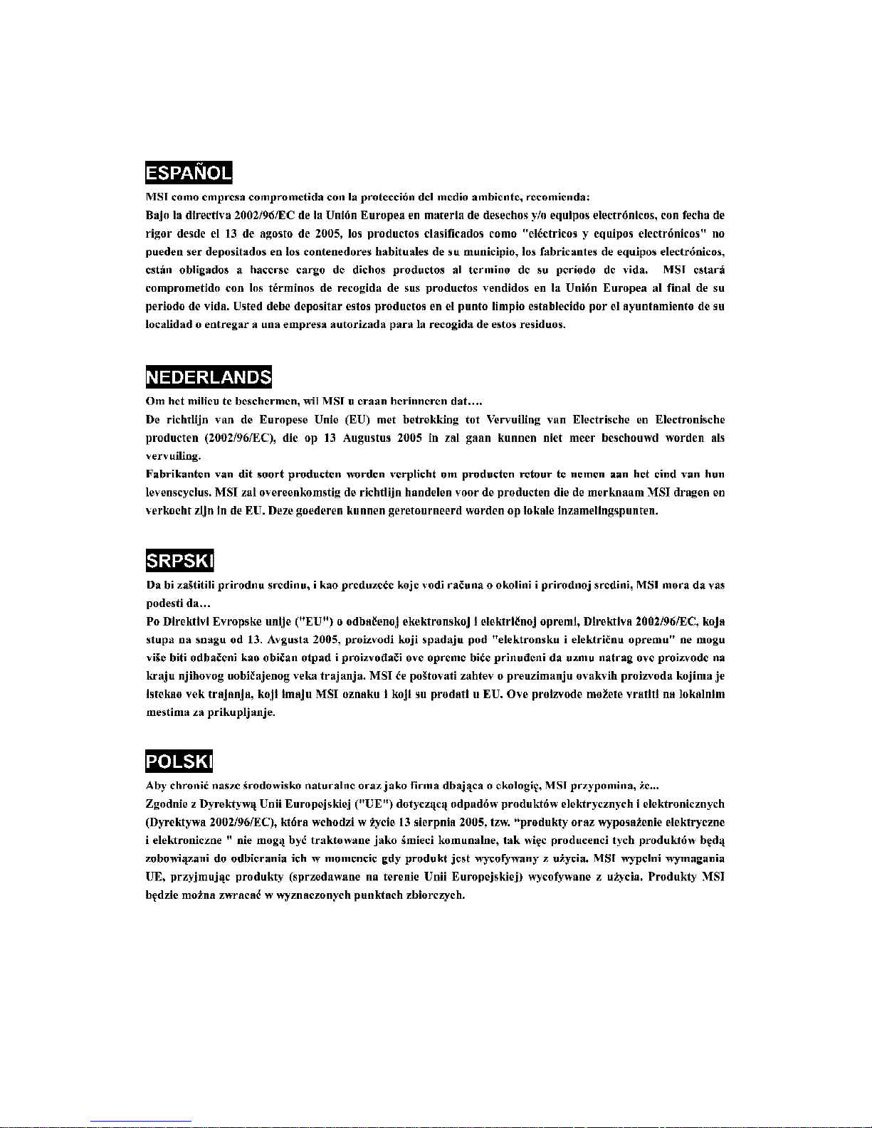
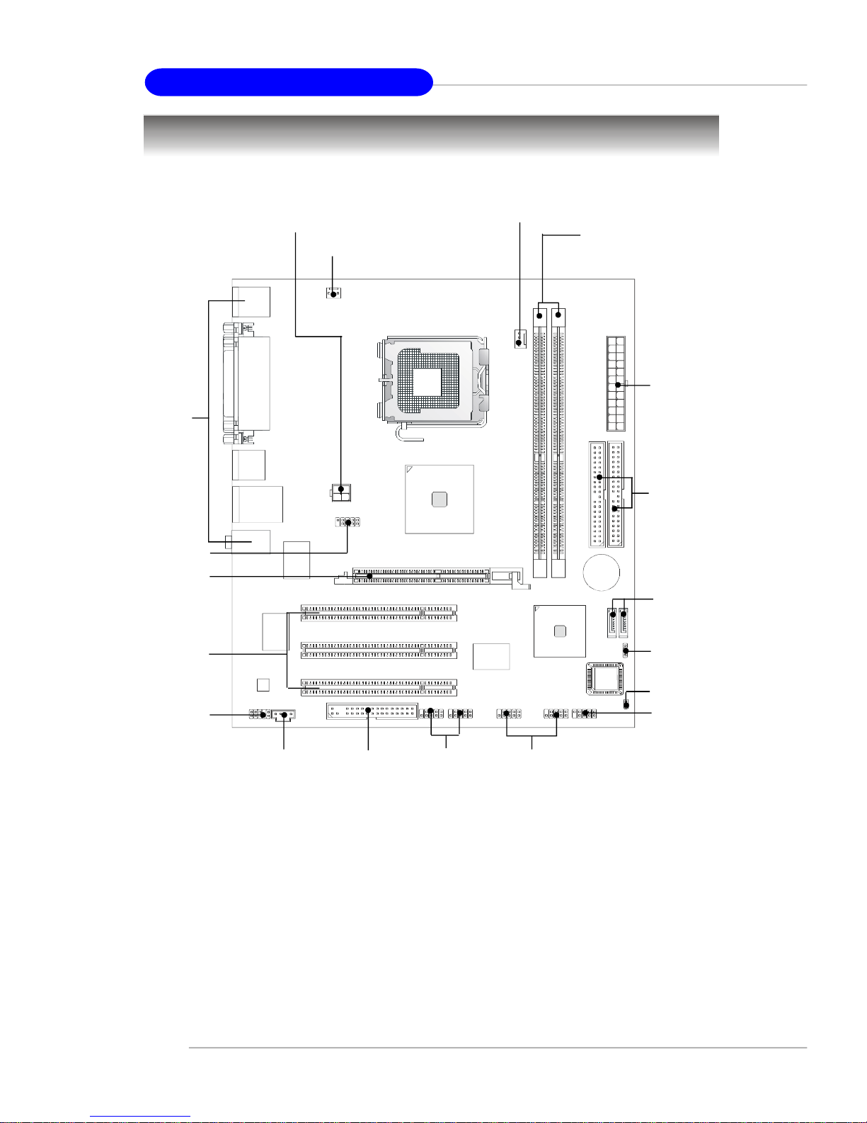
Mainboard Layout
Top:mouse
Bottom:keyboard
Top:
ParallelPort
Bottom:
COM Port
VGA Port
Bottom:USBports
Top:LANjack
Bottom:USBports
T:MIC-In
M:Line-In
B:SSOut
Winbond
W83627EHF
SYS_FAN1
JPW2
COM2
CPU_FAN
1
N
N
O
C
1-4
RTL8100C
AC97
JAUDIO01
PCISlot1
PCISlot2
PCISlot3
CD_IN1
FDD1
1394_J21394_J3
JUSB1
PM8PM (MS-7222 v1.X) Micro-ATX Mainboard
2
T
A
B
J
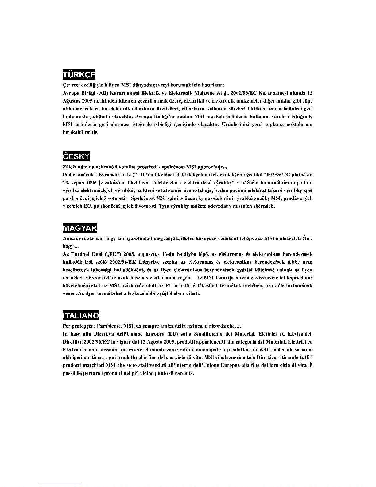
Packing Contents
Getting Started
MSI motherboard
Power Cable
User’s Guide
MSI Driver/Utility CD
COM2 Bracket
(Optional)
Back IO Shield
SATA Cable
Round Cable for
IDE Devices
(Optional)
Round Cable for
Floppy Disk
(Optional)
* The pictures are for reference only. Your packing contents may vary depending on
the model you purchased.
1-5

MS-7222 Micro-ATX Mainboard
MSI Special Feature
The Core Center is a new utility you can find in the CD-ROM disk. The utility is
just like your PC doctor that can detect, view and adjust the PC hardware and system
status during real time operation. In the left side it shows the current system status,
including the Vcore, 3.3V, +5V and 12V. In the right side it shows the current PC
hardware status such as the CPU & system temperatures and all fans speeds.
When you click the red triangles in the left and right sides, two sub-menus will open
for users to adjust the thresholds of system to send out the warning messages.
1-6
Getting Started
Left-wing: Current system status
In the left sub-menu, you can configure the settings of FSB, Vcore, Memory Voltage
and AGP Voltage by clicking the radio button next to each item and make it available
(the radio button will be lighted as yellow when selected), use the “+” and “-” buttons
to adjust, then click “OK” to apply the changes. Then you can click “Save” to save
the values you just configured.
Also you may click “Auto” to start testing the maximum CPU overclocking value. The
CPU FSB will automatically increase the testing value until the PC reboots. Or you may
click “Default” to restore the default values.
Right-wing: PC hardware status during real time operation
In the right sub-menu, here you can configure the PC hardware status such as CPU
& system temperatures and fan speeds. You may use the scroll bars to adjust each
item, then click “OK” to apply the changes. The values you set for the temperatures
are the maximum thresholds for the system for warnings, and the value for fan
speeds are the minimum thresholds.
MSI Reminds You...
Items shown on Core Center vary depending on your system status.
1-7

Hardware Setup
Chapter 2. Hardware Setup
Hardware Setup
This chapter tells you how to install the CPU, memory modules,
and expansion cards, as well as how to setup the jumpers on the
mainboard. Also, it provides the instructions on connecting the peripheral devices, such as the mouse, keyboard, etc.
While doing the installation, be careful in holding the components and follow the installation procedures.
2-1
MS-7222 Micro-ATX Mainboard
+
Quick Components Guide
Back Panel
I/O, p.2-9
COM2,
p.2-14
AGP,
p.2-21
JPW2, p.2-8
SYS_FAN1, p.2-13
CPU_FAN1, p.2-13
DDR DIMMs, p.2-7
CONN1, p.2-8
IDE1, p.2-14
SATA1,2,
p.2-15
PCI Slots 1~3,
p.2-21
JAUDIO1,
p.2-17
2-2
CD_IN1,
p.2-16
FDD1,
p.2-13
1394_J2,3,
p.2-19
JBAT2,
p.2-20
JPW1, p.2-20
JFP1, p.2-16
JUSB1,2
p.2-18
Hardware Setup
Central Processing Unit: CPU
The mainboard supports Intel® Pentium 4 Prescott processor. The mainboard
uses a CPU socket called LGA775. When you are installing the CPU, make sure to
install the cooler to prevent overheating. If you do not have the CPU cooler,
contact your dealer to purchase and install them before turning on the computer.
For the latest information about CPU, please visit http://www.msi.com.tw/
program/products/mainboard/mbd/pro_mbd_cpu_support.php.
MSI Reminds You...
Overheating
Overheating will seriously damage the CPU and system, always make
sure the cooling fan can work properly to protect the CPU from
overheating.
Replacing the CPU
While replacing the CPU, always turn off the ATX power supply or
unplug the power supply’s power cord from grounded outlet first to
ensure the safety of CPU.
Overclocking
This motherboard is designed to support overclocking. However, please
make sure your components are able to tolerate such abnormal setting,
while doing overclocking. Any attempt to operate beyond product specifications is not recommended. We do not guarantee the damages
or risks caused by inadequate operation or beyond product
specifications.
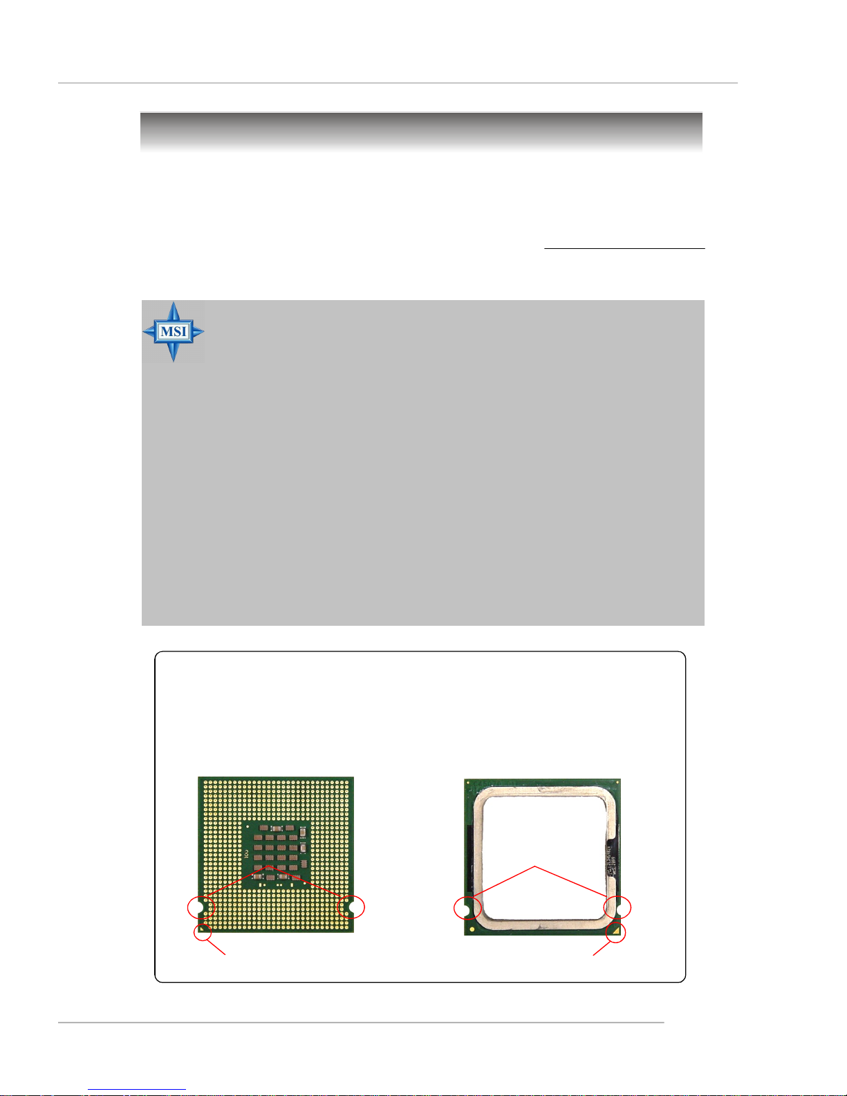
Introduction to LGA 775 CPU
The pin-pad side of LGA 775
CPU.
Alignment Key Alignment Key
The surface of LGA 775 CPU.
Remember to apply some silicone heat transfer compound on
it for better heat dispersion.
Yellow triangle is the Pin 1 indicator
Yellow triangle is the Pin 1 indicator
2-3
MS-7222 Micro-ATX Mainboard
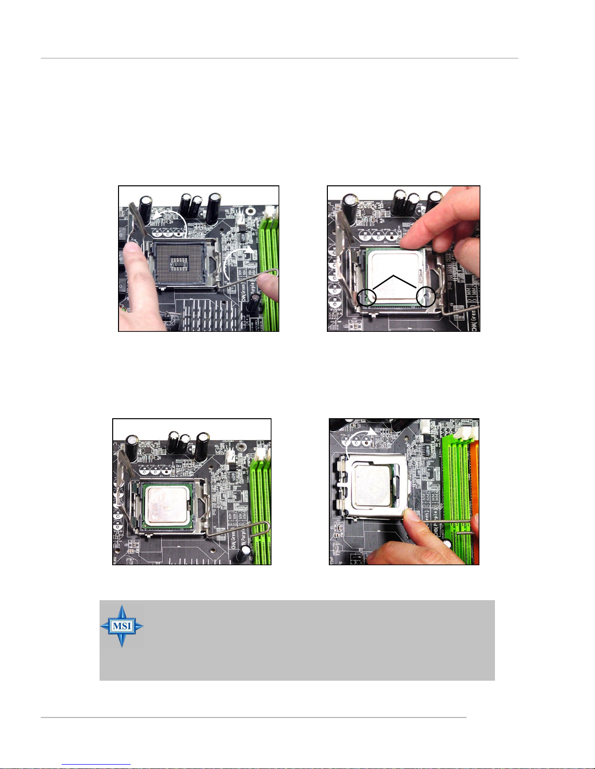
CPU & Cooler Installation
When you are installing the CPU, make sure the CPU has a cooler attached on the top to prevent overheating. If you do not have the cooler, contact
your dealer to purchase and install them before turning on the computer. Meanwhile,
do not forget to apply some silicon heat transfer compound on CPU before installing
the heat sink/cooler fan for better heat dispersion.
Follow the steps below to install the CPU & cooler correctly. Wrong installation
will cause the damage of your CPU & mainboard.
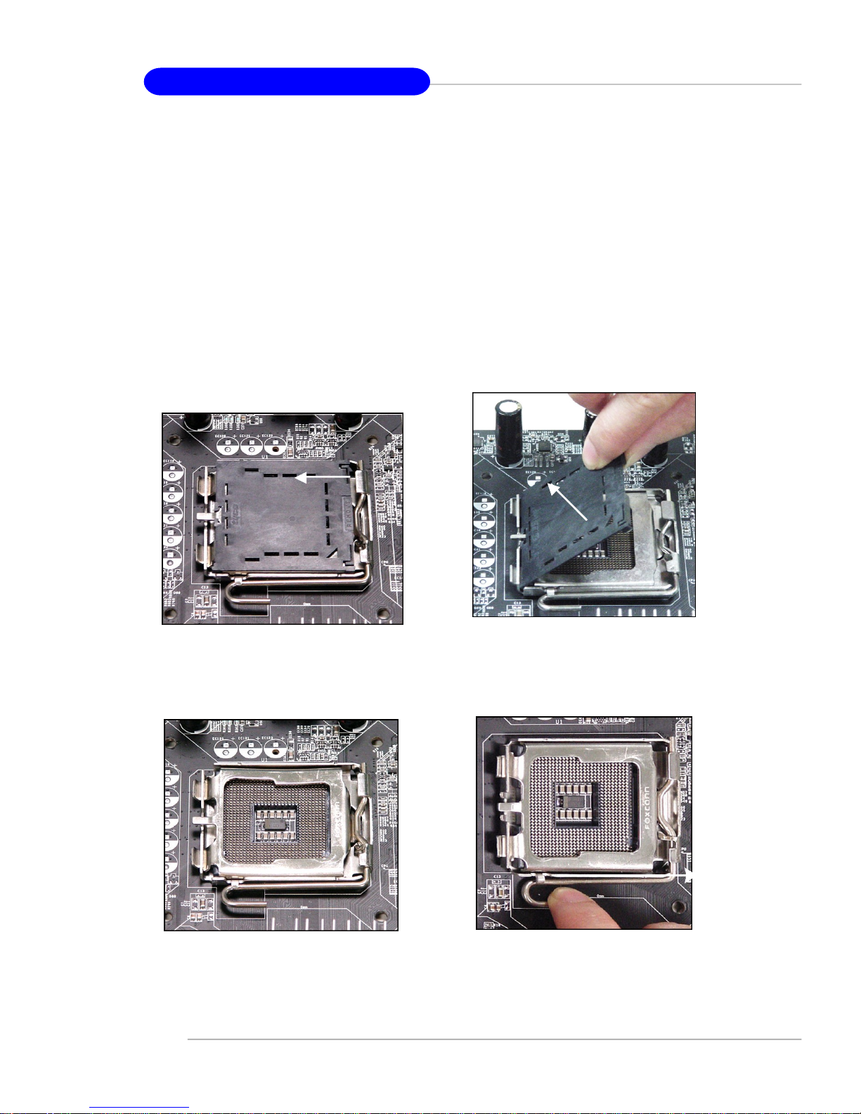
1.The CPU socket has a plastic cap on
it to protect the contact from damage.
Before you install the CPU, always
cover it to protect the socket pin.
2.Remove the cap from lever hinge
side (as the arrow shows).
4.Open the load lever.3.The pins of socket reveal.
2-4
Hardware Setup
5.Lift the load lever up and open the
load plate.
7.Visually inspect if the CPU is
seated well into the socket. If not,
take out the CPU with pure vertical
motion and reinstall.
6.After confirming the CPU direction
for correct mating, put down the
CPU in the socket housing frame.
Be sure to grasp on the edge of
the CPU base. Note that the alignment keys are matched.
alignment
key
8.Cover the load plate onto the
package.
MSI Reminds You...
1.Confirm if your CPU cooler is firmly installed before turning on your
system.
2.Do not touch the CPU socket pins to avoid damaging.
3. The availability of the CPU land side cover depends on your CPU
packing.
2-5

MS-7222 Micro-ATX Mainboard
9.Press down the load lever lightly
onto the load plate, and then secure the lever with the hook under
retention tab.
11.Press the four hooks down to fas-
ten the cooler. Then rotate the locking switch (refer to the correct direction marked on it) to lock the
hooks.
10. Align the holes on the mainboard
with the heatsink. Push down the
cooler until its four clips get
wedged into the holes of the
mainboard.
12.Turn over the mainboard to confirm that the clip-ends are correctly inserted.
2-6
locking
switch
MSI Reminds You...
1.Check the information in PC Health Status in BIOS (Chapter 3) for
the CPU temperature.
2. Whenever CPU is not installed, always protect your CPU socket pin
with the plastic cap covered (shown in step 1) to avoid damaging.
3. Please note that the mating/unmating durability of the CPU is 20 cycles.
Therefore we suggest you do not plug/unplug the CPU too often.
Hardware Setup
Memory
The mainboard provides 2 slots for 240-pin DDR2 DIMM, which supports the
memory size up to 2GB.
Since DDR2 modules are not interchangeable with DDR1 and the DDR2 standard is not backward compatible, you should always install DDR2 memory module in
the DDR2 slot. Otherwise, you are not able to boot up your system and your mainboard
might be damaged.
Introduction to DDR2 SDRAM
DDR2 is a new technology of memory module, and its speed is the top limit of
current DDR1 technology. DDR2 uses a 1.8V supply for core and I/O voltage, compared to 2.5V for DDR1, and requires 28% less power than DDR1 chips. DDR2 truly
is the future of memory, but will require some changes as the technology is not
backwardly compatible and only motherboards specifically designed for DDR2 memory
will be able to support these chips.
DDR2 incorporates new features at the chip level that give it better signal
integrity, thereby enabling higher clock speeds.
DDR2 modules have 240 pins, versus 184 pins on a DDR1 module, and the
length of DDR2 module is 5.25”. DDR2 modules have smaller and tighter spaced pins.
The height of DDR2 modules varies, but they will typically be less than 1.3” in height.
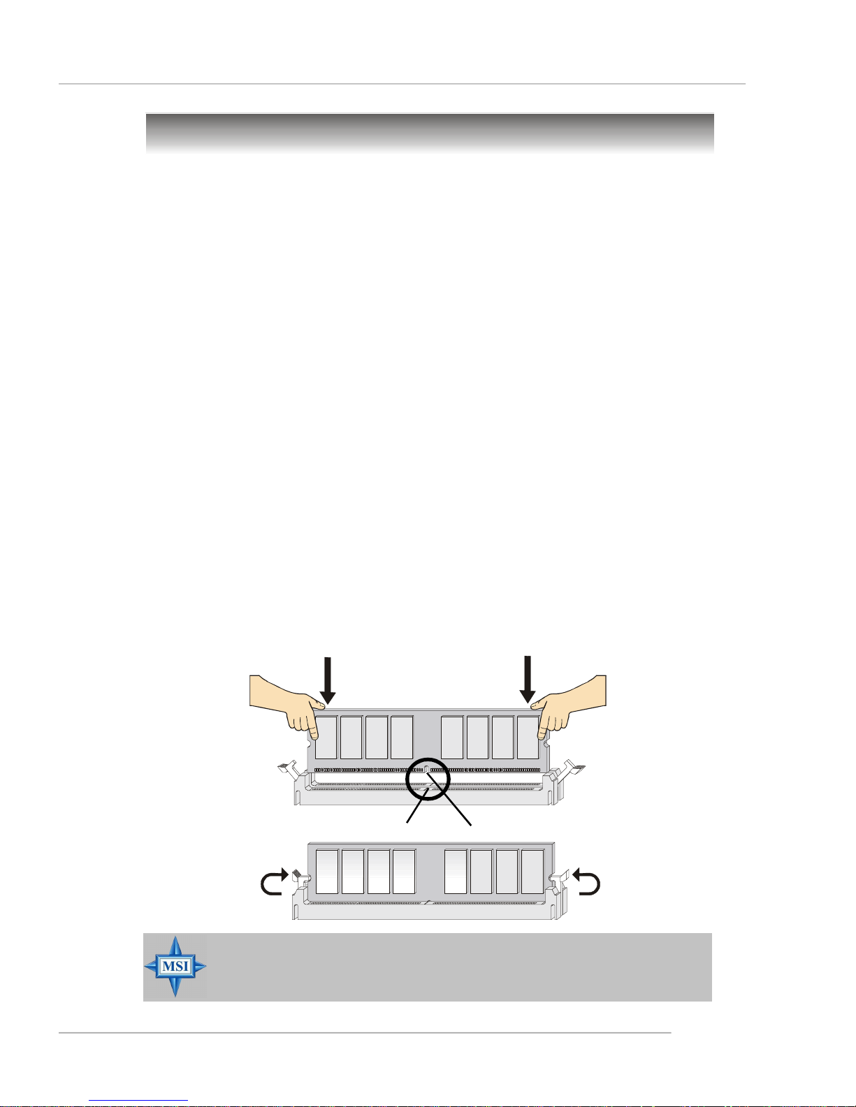
Installing DDR2 Modules
1. The DDR2 DIMM has only one notch on the center of module. The module will
only fit in the right orientation.
2. Insert the DIMM memory module vertically into the DIMM slot. Then push it in
until the golden finger on the memory module is deeply inserted in the socket.
3. The plastic clip at each side of the DIMM slot will automatically close.
Volt
MSI Reminds You...
You can barely see the golden finger if the module is properly inserted in the socket.
Notch
2-7
MS-7222 Micro-ATX Mainboard
Power Supply
The mainboard supports ATX power supply for the power system. Before
inserting the power supply connector, always make sure that all components are
installed properly to ensure that no damage will be caused.
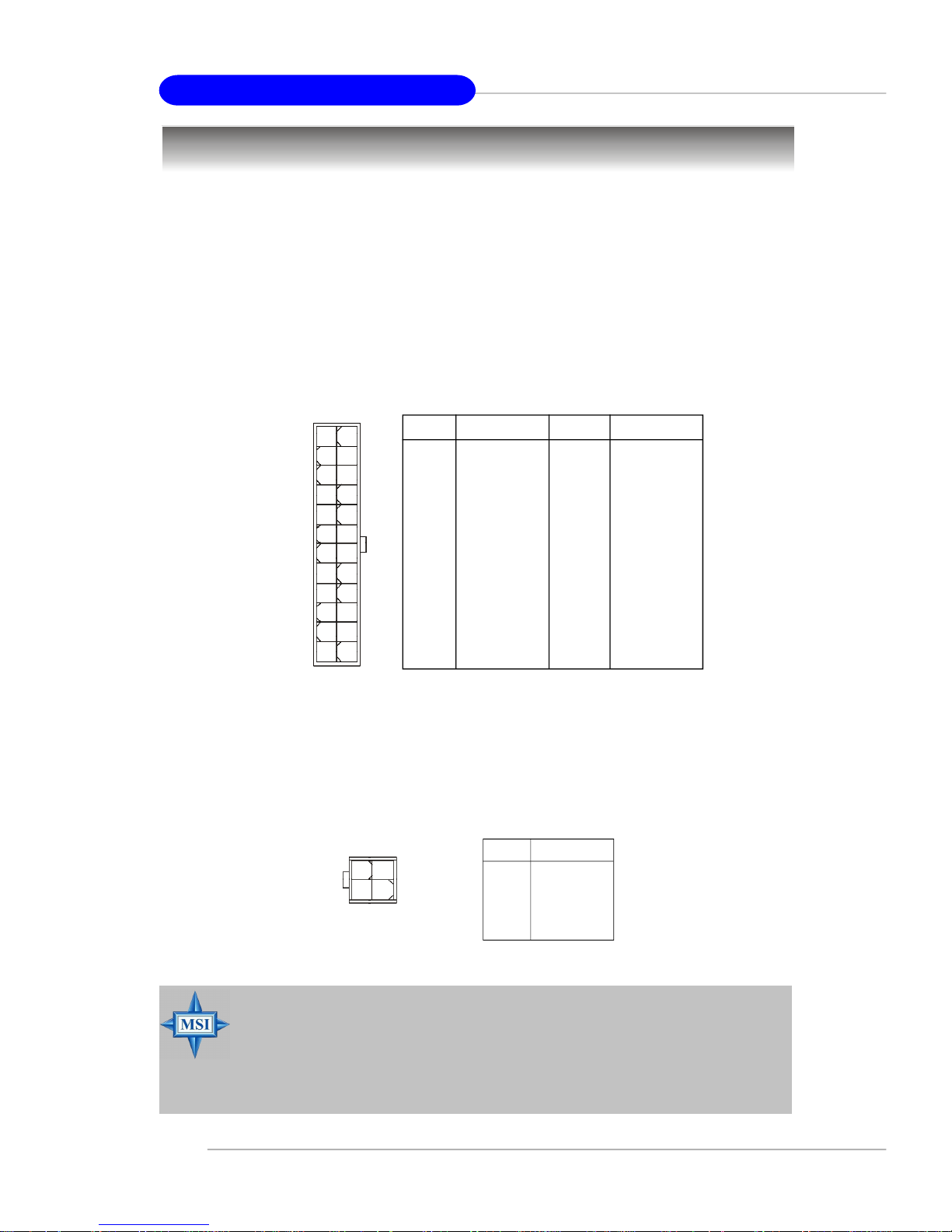
ATX 24-Pin Power Connector: CONN1
The mainboard supports ATX power supply for the power system. Before
inserting the power supply connector, always make sure that all components are
installed properly to ensure that no damage will be caused.
Pin Definition
PIN SIGNAL
1 +3.3V
2 +3.3V
3 GND
4 +5V
5 GND
6 +5V
7 GND
8 PWR OK
9 5VSB
10 +12V
11 +12V
12 NC
ATX1
12
1
24
13
ATX 12V Power Connector: JPW2
This 12V power connector is used to provide power to the CPU.
2
4
JPW2
13
PIN SIGNAL
13 +3.3V
14 -12V
15 GND
16 PS-ON#
17 GND
18 GND
19 GND
20 Res
21 +5V
22 +5V
23 +5V
24 GND
JPW1 Pin Definition
PIN SIGNAL
1 GND
2 GND
3 12V
4 12V
MSI Reminds You...
1. These two connectors connect to the ATX power supply and have to
work together to ensure stable operation of the mainboard.
2. Power supply of 350 watts (and above) is highly recommended for
system stability.
3. ATX 12V power connection should be greater than 18A.
2-8
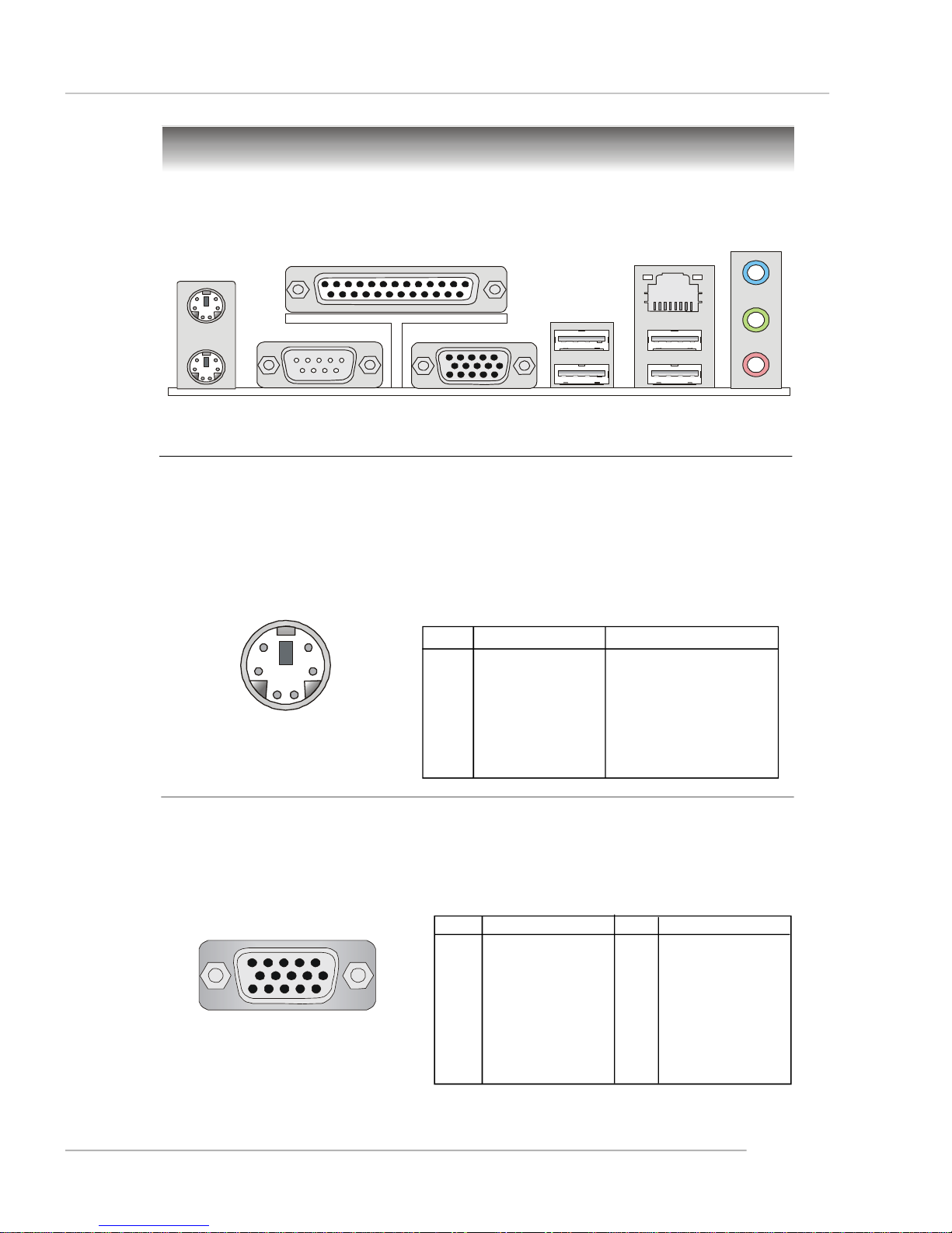
Back Panel
The back panel provides the following connectors:
Hardware Setup
Mouse
Keyboard
COM Port
Parallel
VGA Port
LAN
(optional)
USB Ports
L-In
L-Out
Mic
Mouse/Keyboard Connector
The mainboard provides a standard PS/2® mouse/keyboard mini DIN connector
for attaching a PS/2® mouse/keyboard. You can plug a PS/2® mouse/keyboard directly
into this connector. The connector location and pin assignments are as follows:
Pin Definition
6
4
2
PS/2 Mouse / Keyboard
(6-pin Female)
5
3
1
PIN SIGNAL DESCRIPTION
1 Mouse/Keyboard Data Mouse/Keyboard data
2 NC No connection
3 GND Ground
4 VCC +5V
5 Mouse/Keyboard Clock Mouse/Keyboard clock
6 NC No connection
VGA Connector
The mainboard provides a DB 15-pin female connector to connect a VGA
monitor.
5
15
VGA Connector
(DB 15-pin)
1
11
Pin Signal Description Pin Signal Description
1 RED 2 GREEN
3 BLUE 4 N/C
5 GND 6 GND
7 GND 8 GND
9 +5V 10 GND
11 N/C 12 SDA
13 Horizontal Sync 14 Vertical Sync
15 SCL
2-9
MS-7222 Micro-ATX Mainboard
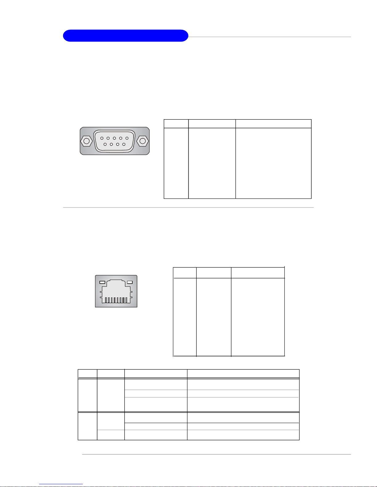
Serial Port Connector
The mainboard offers one 9-pin male DIN connector as the serial port. The port
is a 16550A high speed communication port that sends/receives 16 bytes FIFOs. You
can attach a serial mouse or other serial devices directly to the connector.
Pin Definition
1 2 3 4 5
6 7 8 9
9-Pin Male DIN Connector
PIN SIGNAL DESCRIPTION
1 DCD Data Carry Detect
2 SIN Serial In or Receive Data
3 SOUT Serial Out or Transmit Data
4 DTR Data Terminal Ready)
5 GND Ground
6 DSR Data Set Ready
7 RTS Request To Send
8 CTS Clear To Send
9 RI Ring Indicate
LAN (RJ-45) Jack (optional)
The mainboard provides 1 standard RJ-45 jack for connection to single Local
Area Network (LAN). This LAN enables data to be transferred at 1000(8110SB), 100
or 10Mbps. You can connect a network cable to it.
Pin Definition
PIN SIGNAL DESCRIPTION
1 D0P Differential Pair 0+
2 D0N Differential Pair 03 D1P Differential Pair 1+
RJ-45 LAN Jack
LED Color LED State Condition
Off LAN link is not established.
Left Orange On (steady state) LAN link is established.
On (brighter & pulsing) The computer is communicating with another
4 D2P Differential Pair 2+
5 D2N Differential Pair 26 D1N Differential Pair 17 D3P Differential Pair 3+
8 D3N Differential Pair 3-
computer on the LAN.
Green Off 10 Mbit/sec data rate is selected.
Right On 100 Mbit/sec data rate is selected.
Orange On 1000 Mbit/sec data rate is selected.
2-10
Hardware Setup
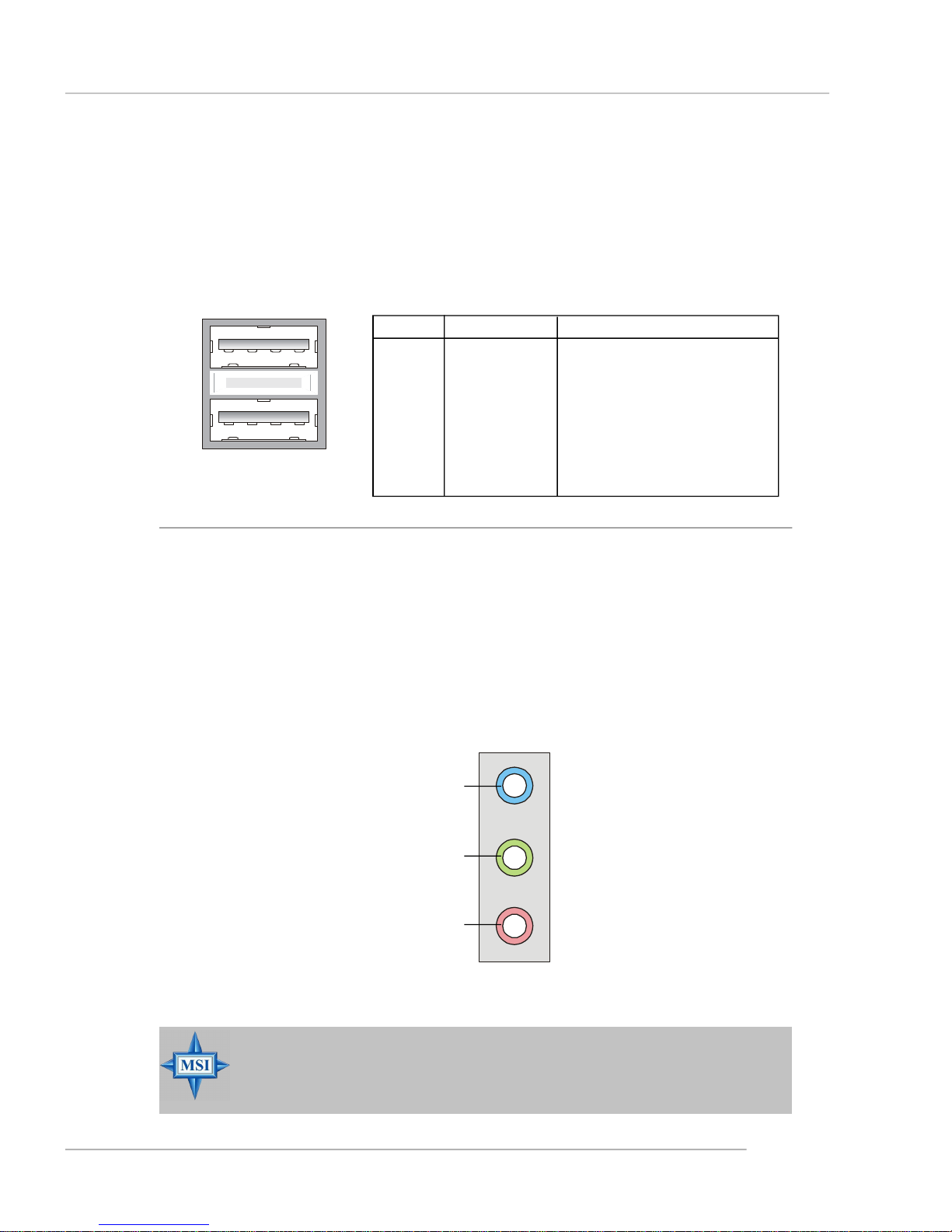
USB Connectors
The mainboard provides an OHCI (Open Host Controller Interface) Universal
Serial Bus root for attaching USB devices such as keyboard, mouse or other USBcompatible devices. You can plug the USB device directly into the connector.
USB Port Description
PIN SIGNAL DESCRIPTION
1 VCC +5V
1 2 3 4
5 6 7 8
USB Ports
2 -Data 0 Negative Data Channel 0
3 +Data0 Positive Data Channel 0
4 GND Ground
5 VCC +5V
6 -Data 1 Negative Data Channel 1
7 +Data 1 Positive Data Channel 1
8 GND Ground
Audio Port Connectors
These 3 audio jacks are for 2-channel mode for stereo speaker output: Line
Out is a connector for Speakers or Headphones. Line In is used for external CD
player, Tape player, or other audio devices. Mic is a connector for microphones.
Line In
Line Out
MIC
MSI Reminds You...
For the advanced functions of the audio codec, please refer to Chapter
4: Introduction to Realtek ALC655 for details.
2-11
 Loading...