


FCC-B Radio Frequency Interference Statement
This equipment has been tested and found to comply with the limits for a class B digital device, pursuant to part 15 of the FCC rules. These limits are designed to provide reasonable protection against harmful interference when the equipment is operated in a commercial environment. This equipment generates, uses and can radiate radio frequency energy and, if not installed and used in accordance with the instruction manual, may cause harmful interference to radio communications. Operation of this equipment in a residential area is likely to cause harmful interference, in which case the user will be required to correct the interference at his own expense.
Notice 1
The changes or modifications not expressly approved by the party responsible for compliance could void the user’s authority to operate the equipment.
Notice 2
Shielded interface cables and A.C. power cord, if any, must be used in order to comply with the emission limits.
VOIR LA NOTICE D’NSTALLATION AVANT DE RACCORDER AU RESEAU.
Micro-Star International
MS-7104
This device complies with Part 15 of the FCC Rules. Operation is subject to the following two conditions:
(1)this device may not cause harmful interference, and
(2)this device must accept any interference received, including interference that may cause undesired
operation
G52-M7104X1
i
Copyright Notice
The material in this document is the intellectual property of MICRO-STAR INTERNATIONAL. We take every care in the preparation of this document, but no guarantee is given as to the correctness of its contents. Our products are under continual improvement and we reserve the right to make changes without notice.
Trademarks
All trademarks are the properties of their respective owners.
AMD, Athlon™ Athlon™XP, Thoroughbred™ and Duron™ are registered trademarks of AMD Corporation. Intel® and Pentium® are registered trademarks of Intel Corporation.
PS/2 and OS® 2 are registered trademarks of International Business Machines Corporation. Microsoft® is a registered trademark of Microsoft Corporation. Windows® 98/2000/NT/XP are registered trademarks of Microsoft Corporation.
NVIDIA, the NVIDIA logo, DualNet, and nForce are registered trademarks or trademarks of NVIDIA Corporation in the United States and/or other countries.
Netware® is a registered trademark of Novell, Inc.
Award® is a registered trademark of Phoenix Technologies Ltd.
AMI® is a registered trademark of American Megatrends Inc.
Kensington and MicroSaver are registered trademarks of the Kensington Technology Group.
PCMCIA and CardBus are registered trademarks of the Personal Computer Memory Card International Association.
Revision History
Revision |
Revision History |
Date |
V1.0 |
First release of V-Series with VIA |
January 2005 |
|
P4M800/VT8237R chipsets |
|
ii

Safety Instructions
1.Always read the safety instructions carefully.
2.Keep this User Manual for future reference.
3.Keep this equipment away from humidity.
4.Lay this equipment on a reliable flat surface before setting it up.
5.The openings on the enclosure are for air convection hence protects the equipment from overheating. Do not cover the openings.
6.Make sure the voltage of the power source and adjust properly 110/220V before connecting the equipment to the power inlet.
7.Place the power cord such a way that people can not step on it. Do not place anything over the power cord.
8.Always Unplug the Power Cord before inserting any add-on card or module.
9.All cautions and warnings on the equipment should be noted.
10.Never pour any liquid into the opening that could damage or cause electrical shock.
11.If any of the following situations arises, get the equipment checked by a service personnel:
-The power cord or plug is damaged.
-Liquid has penetrated into the equipment.
-The equipment has been exposed to moisture.
- The equipment does not work well or you can not get it work according to User Manual.
-The equipment has dropped and damaged.
-The equipment has obvious sign of breakage.
12.Do not leave this equipment in an environment unconditioned, storage temperature above 60° C (140°F), it may damage the equipment.
iii
|
Table of Contents |
English .................................................................... |
1 |
Français .................................................................. |
17 |
Deutsch................................................................... |
31 |
................................................................... |
47 |
................................................................... |
61 |
...................................................................... |
75 |
iv

Introduction
Thank you for purchasing the PM8M-V Series (MS-7104 v1.X) M-ATX mainboard. This mainboard is based on VIA P4M800 and VT8237R chipsets for optimal system efficiency. Designed to fit the advanced Intel Pentium 4 Prescott processor, the PM8M-V Series mainboard delivers a high performance and professional desktop platform solution.
Specifications
CPU
•Supports Intel Pentium 4 /Prescott (Socket 478) processor
•Supports up to 3.4GHz, FSB@800/533MHz
(For the latest information about CPU, please visit our Web site at http://www.msi.com.tw/program/products/mainboard/mbd/pro_mbd_cpu_support.php )
Chipset
•VIA P4M800 chipset (645 BGA)
-64 bit P4 processor FSB I/F (800MHz)
-64 bit DDR SDRAM memory I/F (333/400MHz)
-32 bit AGP I/F (66MHz) for 8x/4x mode
-Supports 8X V-Link
•VIA VT8237R chipset (487 BGA)
-Integrated Hardware Sound Blaster/Direct Sound AC97 audio
-Ultra DMA 66/100/133 master mode PCI EIDE controller
-Supports USB 2.0 up to 8 ports
-ACPI & PC2001 compliant enhanced power management
Main Memory
•Supports four memory banks using two 184-pin DDR DIMMs
•Supports up to 2GB PC 3200 (DDR400) SDRAMs
•Supports 2.5v DDR SDRAM
(For the updated supporting memory modules, please visit our Web site at http://www.msi.com.tw/program/products/mainboard/mbd/pro_mbd_trp_list.php )
Slots
•One AGP (Accelerated Graphics Port) 8X slot
•Three PCI 2.2 32-bit PCI bus slots (support 3.3v/5v PCI bus interface)
1
Onboard IDE
-An IDE controller integrated in the VIA VT8237R chipset providing IDE HDD/CD-ROM with PIO, Bus Master and Ultra DMA 66/100/133 operation modes
-Can connect up to four IDE devices
On-Board Peripherals
•On-Board Peripherals include:
-1 floppy port supports 1 FDD with 360K, 720K, 1.2M, 1.44M and 2.88Mbytes
-1 serial port (COM A)
-1 parallel port supports SPP/EPP/ECP mode
-8 USB 2.0 ports (Rear x4 / Front x4)
-1 audio (Line-In/Line-Out/Mic) port
-1 RJ45 LAN jack
-1 COM B pin header
-2 SATA 150
-1 VGA port
Audio
•AC97 link controller integrated in VT8237R
•Realtek ALC655 6-Channel software audio codec
-Compliant with AC97 v2.2 spec.
LAN
•Realtek 8201CL
-Integrated Fast Ethernet PHY
-Supports 10Mb/s, 100Mb/s
-Compliant with PCI 2.2
-Supports ACPI Power Management
BIOS
•The mainboard BIOS provides Plug & Play BIOS which detects the peripheral devices and expansion cards of the board automatically
•The mainboard provides a Desktop Management Interface (DMI) function which records
your mainboard specifications
Dimension
•Micro-ATX Form Factor: 245mm x 190mm
Mounting
•6 standard mounting holes
2

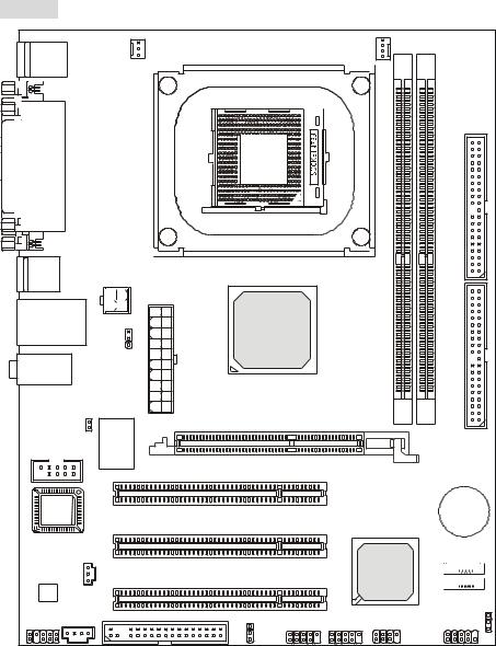
Layout |
|
|
|
|
|
|
Top: Mouse |
|
SYS_FAN |
|
CPU_FAN |
|
|
|
|
|
|
|
|
|
Bottom: Keyboard |
|
|
|
DIMM1 |
DIMM2 |
|
|
|
|
|
|
||
Top: Parallel Port |
|
|
|
|
|
|
Bottom: |
|
|
|
|
|
|
COM A |
|
|
|
|
|
|
VGA Port |
|
|
|
|
|
IDE2 |
|
|
|
|
|
|
|
USB |
|
|
|
|
|
|
Ports |
|
|
|
|
|
|
|
|
ATX1 |
|
|
|
|
Top: LAN Jack |
JPW1 |
VIA |
|
|
|
|
Bottom: USB |
|
|
|
|||
Ports |
|
|
P4M800 |
|
|
IDE1 |
T: Line-In |
|
J3 |
|
|
|
|
|
|
|
|
|
||
M: Line-Out |
|
|
|
|
|
|
B: Mic |
|
|
|
|
|
|
JCASE1 |
83627THF |
|
|
|
|
|
|
Winbond |
AGP Slot |
|
|
|
|
JCOM 1 |
|
|
|
|
||
|
|
|
|
|
||
|
|
W |
PCI Slot 1 |
|
|
|
|
|
|
|
|
|
|
BIOS |
|
|
|
|
|
BATT |
|
|
|
PCI Slot 2 |
|
|
+ |
|
|
|
|
|
|
|
JSP1 |
|
|
|
|
VIA |
SATA2 |
|
|
|
|
|
|
|
Codec |
|
|
PCI Slot 3 |
|
VT8237R |
|
|
|
|
|
|
|
SATA1 |
JAUDIO1CD_IN1 |
|
|
FDD 1 |
|
|
JBAT1 |
|
|
JUSB1 |
JUSB2 |
JFP2 |
JFP1 |
|
|
|
|
J4 |
|
|
|
MS-7104v1.X Micro-ATX Mainboard
3
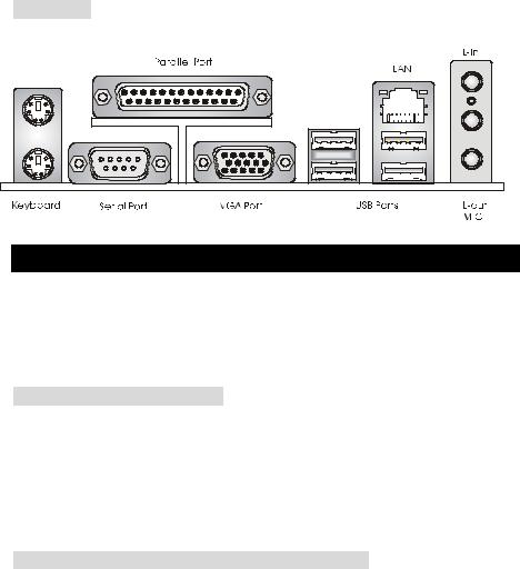
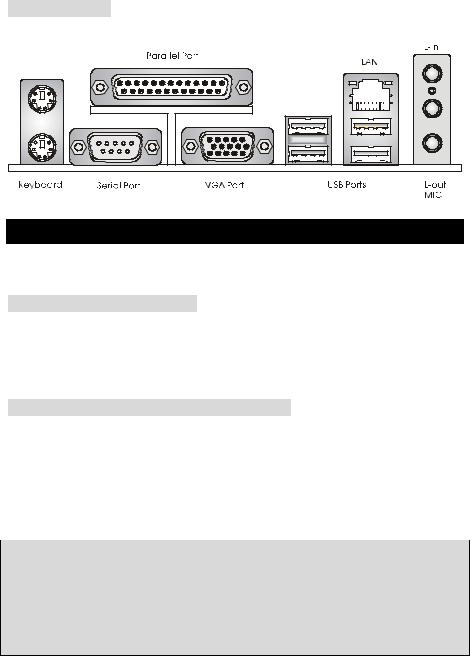
Rear Panel
The back panel provides the following connectors:
Mouse
Hardware Setup
This chapter tells you how to install the CPU, memory modules, and expansion cards, as well as how to setup the jumpers on the mainboard. It also provides the instructions on connecting the peripheral devices, such as the mouse, keyboard, etc. While doing the installation, be careful in holding the components and follow the installation procedures.
Central Processing Unit: CPU
The mainboard supports Intel Pentium 4 Prescott processor. When you are installing the CPU, make sure the CPU has a heat sink and a cooling fan attached on the top to prevent overheating. If you do not find the heat sink and cooling fan, contact your dealer to purchase and install them before turning on the computer. (For the latest information about CPU, please visit our Web site at http://www.msi.com.tw/program/products/mainboard/mbd/pro_mbd_cpu_support.php
Example of CPU Core Speed Derivation Procedure
If |
CPU Clock |
= |
133MHz |
|
Core/Bus ratio |
= |
23 |
then |
CPU core speed |
= |
Host Clock x Core/Bus ratio |
|
|
= |
133MHz x 23 |
|
|
= |
3.06 GHz |
4

MSI Reminds You...
Overheating
Overheating will seriously damage the CPU and system, always make sure the cooling fan can work properly to protect the CPU from overheating.
Replacing the CPU
While replacing the CPU, always turn off the ATX power supply or unplug the power supply’s power cord from grounded outlet first to ensure the safety of CPU.
CPU Installation Procedures for Socket 478
1.Please turn off the power and unplug the power cord before installing the CPU.
2.Pull the lever sideways away from the socket. Make sure to raise the lever up to a 90-degree angle.
3.Look for the gold arrow. The gold arrow should point towards the lever pivot. The CPU can only fit in the correct orientation.
4.If the CPU is correctly installed, the pins should be completely embedded into the socket and can not be seen. Please note that any violation of the correct installation procedures may cause permanent damages to your mainboard.
5.Press the CPU down firmly into the socket and close the lever. As the CPU is likely to move while the lever is being closed, always close the lever with your fingers pressing tightly on top of the CPU to make sure the CPU is properly and completely embedded into the socket.
Installing the CPU Fan
As processor technology pushes to faster speeds and higher performance, thermal management becomes increasingly important. To dissipate heat, you need to attach the CPU cooling fan and heatsink on top of the CPU. Follow the instructions below to install the Heatsink/Fan:
1.Locate the CPU and its retention mechanism on the motherboard.
2.Position the heatsink onto the retention mechanism.
3.Mount the fan on top of the heatsink. Press down the fan until its four clips get wedged in the holes of the retention mechanism.
5
4.Press the two levers down to fasten the fan. Each lever can be pressed down in only ONE direction.
5.Connect the fan power cable from the mounted fan to the 3-pin fan power connector on the board.
MSI Reminds You...
1.Confirm if your CPU cooler is firmly installed before turning on your system.
2.Check the information in PC Health Status of H/W Monitor in BIOS for the CPU temperature.
3.Do not touch the CPU socket pins to avoid damage.
Memory
The mainboard provides 2 slots for 184-pin DDR SDRAM DIMM (Double In-Line Memory Module) modules and supports the memory size up to 2GB. Install at least one DIMM module on the slots. Each DIMM slot supports up to a maximum size of 1GB. You can install either singleor double-sided modules to meet your own needs.
Please refer to http://www.msi.com.tw/program/products/mainboard/mbd/pro_mbd_trp_list.php for compatible DDR modules.
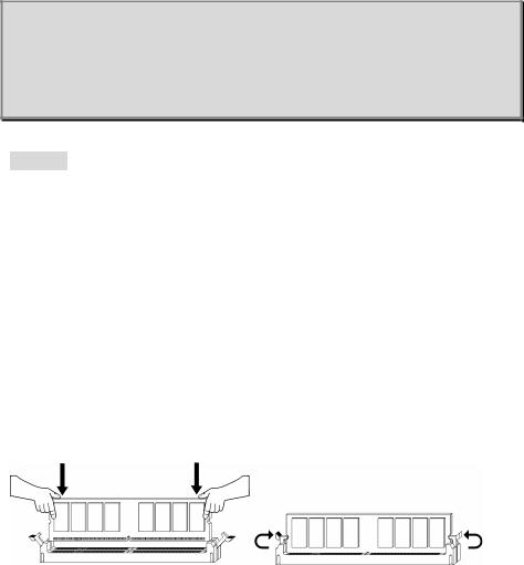
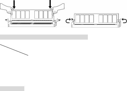
Installing DDR Modules
1.The DDR DIMM has only one notch on the center of module. The module will only fit in the right orientation.
2.Insert the DIMM memory module vertically into the DIMM slot. Then push it in until the golden finger on the memory module is deeply inserted in the socket.
3.The plastic clip at each side of the DIMM slot will automatically close.
6
Memory Speed/CPU FSB Support Matrix
Memory |
DDR333 |
DDR 400 |
|
FSB |
|||
|
|
||
|
|
|
|
133 MHz |
YES |
YES |
|
|
|
|
|
166 MHz |
YES |
YES |
|
|
|
|
|
200MHz |
YES |
YES |
|
|
|
|
For the updated supporting memory modules, please visit our Web site at http://www.msi.com.tw/program/products/mainboard/mbd/pro_mbd_trp_list.php
Power Supply
The mainboard supports ATX power supply for the power system. Before inserting the power supply connector, always make sure that all components are installed properly to ensure that no damage will be caused. Power supplies of 300watt (and up) are highly recommended for system stability.
ATX 20-Pin Power Connector: ATX1 |
|
1 |
2V |
|
5V_SB |
||
This connector allows you to connect to an ATX power supply. To |
PW_OK |
||
connect to the ATX power supply, make sure the plug of the power |
GND |
||
|
5V |
||
supply is inserted in the proper orientation and the pins are aligned. |
G ND |
||
|
5V |
||
|
|
|
|
Then push down the power supply firmly into the connector. |
G ND |
||
|
|
3. |
3V |
|
|
3. |
3V |
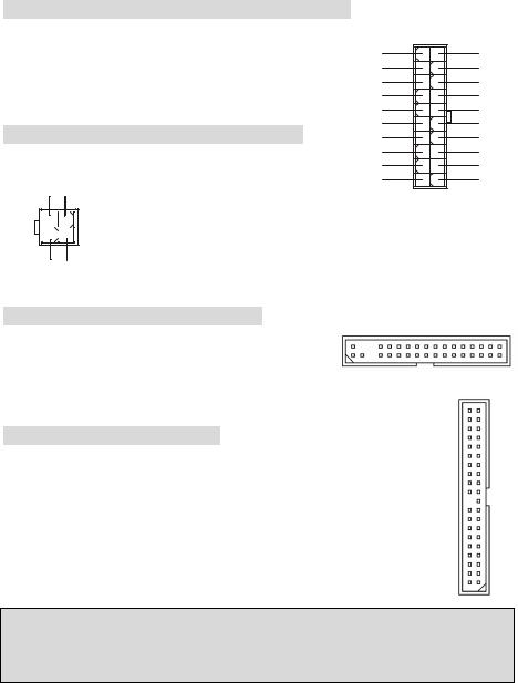
ATX 12V Power Connector: JPW1
This 12V power connector is used to provide power to the CPU.
12V GND
4 |
2 |
3 |
1 |
12V GND
10 |
20 |
|
5V |
|
5V |
|
- 5V |
|
GND |
|
GND |
|
GND |
|
PS_ON |
|
GND |
|
- 12V |
|
3 .3V |
1 |
11 |
Floppy Disk Drive Connector: FDD1
The mainboard provides a standard floppy disk drive connector that supports 360K, 720K, 1.2M, 1.44M and 2.88M floppy disk types.
7
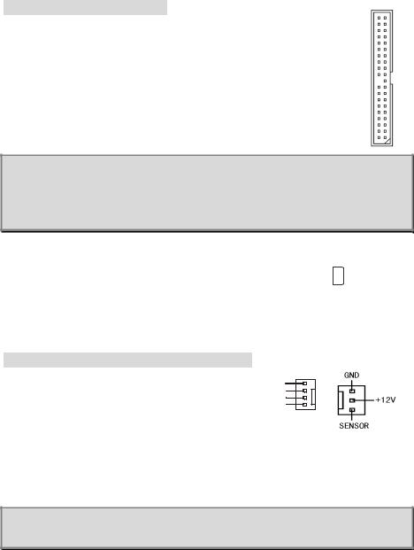
IDE Connectors: IDE1 & IDE2
The mainboard has a 32-bit Enhanced PCI IDE and Ultra DMA 33/66/100/133 controller that provides PIO mode 0~4, Bus Master, and Ultra DMA 33/66/100/133 function. You can connect up to four hard disk drives, CD-ROM, 120MB Floppy and other devices.
The first hard drive should always be connected to IDE1. IDE1 can connect a Master and a Slave drive. You must configure second hard drive to Slave mode by setting the jumper accordingly. IDE2 can also connect a Master and a Slave drive.
MSI Reminds You...
If you install two hard disks on cable, you must configure the second drive to Slave mode by setting its jumper. Refer to the hard disk documentation supplied by hard disk vendors for jumper setting instructions.
Chassis Intrusion Switch Connector: JCASE1 |
|
2 |
|
|
|
|
|
|
GN D |
This connector is connected to 2-pin connector chassis switch. If the |
1 |
|
|
|
|
|
|
C I NTRO |
|
|
|
|
|
|
|
||||
|
|
|
|
|
|
|
|
||
Chassis is open, the switch will be short. The system will record this status. To clear the warning,
you must enter the BIOS setting and clear the status.
Fan Power Connectors: CPU_FAN/SYS_FAN
The CPU_FAN (processor fan) and SYS_FAN (system fan) support system cooling fan with +12V. They support three-pin head connector. When connecting the wire to the
connectors, always note that the red wire is the positive and should be
connected to the +12V, the black wire is Ground and should be connected to GND. If the mainboard has a System Hardware Monitor chipset on-board, you must use a specially designed fan with speed sensor to take advantage of the CPU fan control.
MSI Reminds You...
Always consult the vendors for proper CPU cooling fan.
8
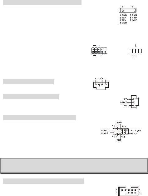
Serial ATA Connectors: SATA1 & SATA2
The mainboard provides dual high-speed Serial ATA interface ports. The ports support 1st generation Serial ATA data rates of 150MB/s and are fully compliant with Serial ATA 1.0 specifications. Each Serial ATA connector can connect to 1 hard disk drive.
|
|
Power |
Power |
||||||
Front Panel Connectors: JFP1 & JFP2 |
|
LED |
Switch |
||||||
|
|
2 |
|
|
|
|
|
|
10 |
The mainboard provides two front panel connectors for |
|
|
|
|
|
|
|||
|
|
|
|||||||
1 |
|
|
|
9 |
|||||
|
|
|
|||||||
electrical connection to the front panel switches and |
|
|
|
|
|
||||
|
|
|
|
||||||
HDD |
Reset |
||||||||
|
|
LED |
Switch |
||||||
LEDs. The JFP1 is compliant with Intel Front Panel I/O
JFP1
Connectivity Design Guide.
Speaker
2 


 8 1
8 1 


 7
7
Power
LED
JFP2
CD-In Connector: CD_IN1
The connector is for CD-ROM audio connector.
SPDIF-Out Connector: JSP1
This connector is used to connect SPDIF (Sony & Philips Digital Interconnect Format) interface for digital audio transmission.
Front USB Connector: JUSB1/JUSB2
The mainboard provides two standard USB 2.0 pin headers JUSB1&JUSB2. USB2.0 technology increases data transfer rate
up to a maximum throughput of 480Mbps, which is 40 times faster than USB 1.1, and is ideal for connecting high-speed USB
interface peripherals such as USB HDD, digital cameras, MP3 players, printers, modems and the like.
MSI Reminds You...
Note that the pins of VCC and GND must be connected correctly or it may cause some damage.
Serial Port Connector: JCOM1 (Optional)
The mainboard offers one 9-pin male DIN connector COM A (on the rear panel), and one optional serial port JCOM1. Both are 16550A high speed communication ports that send/receive/ 16 bytes FIFOs. You can attach a serial mouse or other serial device directly to them.
9
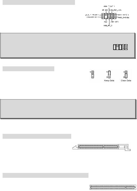
Front Panel Audio Connector: JAUDIO1
The front panel audio connector allows you to connect to
the front panel audio and is compliant with Intel ® Front
Panel I/O Connectivity Design Guide.
MSI Reminds You...
If you do not want to connect to the front audio header, pins 5 & 6, 9 & 10
|
9 |
1 |
have to be jumpered in order to have signal output directed to the rear |
10 |
2 |
audio ports. Otherwise, the Line-Out connector on the back panel will not function.
Clear CMOS Jumper: JBAT1
There is a CMOS RAM on board that has a power supply from external battery to keep the system configuration data.
With the CMOS RAM, the system can automatically boot OS every time it is turned on. If you want to clear the system configuration, use the JBAT1 (Clear CMOS Jumper) to clear data.
MSI Reminds You...
You can clear CMOS by shorting 2-3 pin while the system is off. Then return to 1-2 pin position. Avoid clearing the CMOS while the system is on; it will damage the mainboard.
The mainboard provides one AGP slot, three 32-bit PCI bus slots.
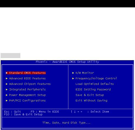
AGP (Accelerated Graphics Port) Slot
The AGP slot allows you to insert the AGP graphics card. AGP is an interface specification designed for the throughput demands of 3D
graphics. It introduces a 66MHz, 32-bit channel for the graphics controller to directly access main memory. The slot supports 8x/4x AGP card.
PCI (Peripheral Component Interconnect) Slots
The PCI slots allow you to insert the expansion cards to meet your needs. When adding or removing expansion cards, make sure that you unplug the power supply first. Meanwhile,
10

read the documentation for the expansion card to make any necessary hardware or software settings for the expansion card, such as jumpers, switches or BIOS configuration.
PCI Interrupt Request Routing
The IRQ, acronym of interrupt request line and pronounced I-R-Q, are hardware lines over which devices can send interrupt signals to the microprocessor. The PCI IRQ pins are typically connected to the PCI bus INT A# ~ INT D# pins as follows:
|
Order 1 |
Order 2 |
Order 3 |
Order 4 |
|
|
|
|
|
PCI Slot 1 |
INT B# |
INT C# |
INT D# |
INT A# |
|
|
|
|
|
PCI Slot 2 |
INT C# |
INT D# |
INT A# |
INT B# |
|
|
|
|
|
PCI Slot 3 |
INT D# |
INT A# |
INT B# |
INT C# |
|
|
|
|
|
11
BIOS Setup
Power on the computer and the system will start POST (Power On Self Test) process. When the message below appears on the screen, press <DEL> key to enter Setup.
DEL: Setup
If the message disappears before you respond and you still wish to enter Setup, restart the system by turning it OFF and On or pressing the RESET button. You may also restart the system by simultaneously pressing <Ctrl>, <Alt>, and <Delete> keys.
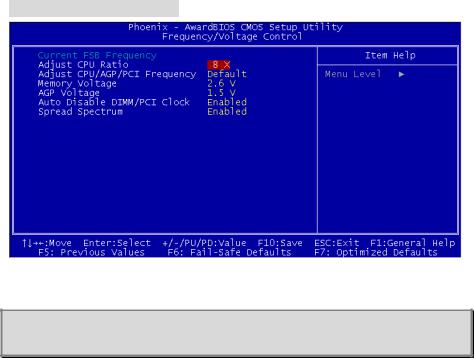
Main Page
Standard CMOS Features
Use this menu for basic system configurations, such as time, date etc.
Advanced BIOS Features
Use this menu to setup the items of special enhanced features.
Advanced Chipset Features
Use this menu to change the values in the chipset registers and optimize your system performance.
Integrated Peripherals
Use this menu to specify your settings for integrated peripherals.
Power Management Features
Use this menu to specify your settings for power management.
PNP/PCI Configurations
This entry appears if your system supports PnP/PCI.
H/W Monitor
This entry shows information of your CPU, fan and overall system status.
12
Frequency/Voltage Control
Use this menu to specify your settings for CPU/AGP frequency/voltage control and overclocking.
Load Optimized Defaults
Use this menu to load the BIOS values for the best system performance, but the system stability may be affected.
BIOS Setting Password
Use this menu to set User Password.
Save & Exit Setup
Save changes to CMOS and exit setup.
Exit Without Saving
Abandon all changes and exit setup.
13
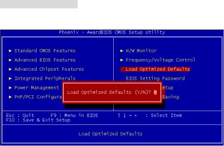
Frequency/Voltage Control
The items in this submenu includes some important settings of CPU, AGP, DRAM and
overclocking functions.
MSI Reminds You...
Change these settings only if you are familiar with the chipset.
Current FSB Frequency
It shows the current clock frequency of the front side bus. (read only)
Adjust CPU Ratio
This setting controls the multiplier that is used to determine the internal clock speed of the processor relative to the external or motherboard clock speed.
Adjust CPU/AGP/PCI Frequency
This setting allows you to select the clock frequency of CPU/AGP/PCI.
Memory Voltage
Adjusting the DDR voltage can increase the DDR speed. Any changes made to this setting may cause a stability issue, so changing the DDR voltage for long-term purpose is NOT recommended.
AGP Voltage
AGP voltage is adjustable in the field, allowing you to increase the performance of your AGP display card when overclocking, but the stability may be affected.
Auto Disable DIMM/PCI Clock
This item is used to auto detect the DIMM/PCI slots. When set to [Enabled], the system will remove (turn off) clocks from empty DIMM/PCI slots to minimize the electromagnetic interference (EMI).
14
Spread Spectrum
When the motherboard’s clock generator pulses, the extreme values (spikes) of the pulses create EMI (Electromagnetic Interference). The Spread Spectrum function reduces the EMI generated by modulating the pulses so that the spikes of the pulses are reduced to flatter curves. If you do not have any EMI problem, leave the setting at Disabled for optimal system stability and performance. But if you are plagued by EMI, select one of the options for EMI reduction. Remember to disable Spread Spectrum if you are overclocking because even a slight jitter can introduce a temporary boost in clockspeed which may just cause your overclocked processor to lock up.
15
Load Optimized Defaults
You can load the optimized values provided by the mainboard manufacturer for the stable performance.
16
Introduction
Félicitations, vous venez d’acquérir une carte mère M-ATX PM8M-V Series (MS-7104 v1.X). Cette carte mère est basée sur les Chipsets VIA P4M800 et VT8237R offrant un système très performant. La carte fonctionne avec les processeurs Intel Pentium 4 Prescott, la PM8M-V Series est très performante et offre une solution adaptée tant aux professionnels qu’aux particuliers.
Spécificités
CPU
•Supporte les processeurs Intel Pentium 4 Prescott (Socket 478)
•Supporte jusqu’à 3.4GHz, FSB@800/533MHz
(Pour les dernières mises à jours concernant les CPU, vous pouvez visiter : http://www.msi.com.tw/program/products/mainboard/mbd/pro_mbd_cpu_support.php.)
Chipset
•Chipset VIA P4M800 (645 BGA)
-Processeur I/F FSB P4 64 bit (800MHz)
-Mémoire I/F DDR SDRAM 64 bit (333/400MHz)
-Mode I/F AGP 32 bit (66MHz) pour 8x/4x
-Supporte V-Link 8X
•Chipset VIA VT8237R (487 BGA)
-Hardware Sound Blaster/Direct Sound AC97 audio intégré
-Contrôleur Ultra DMA 66/100/133 master mode PCI EIDE
-Supporte USB 2.0 jusqu’à 8 ports
-Supporte à la fois l’ACPI et la gestion de l’alimentation
Mémoire Principale
•Supporte quatre banques de mémoire DDR DIMM (184 broches)
•Supporte jusqu’à 2GB DDR400 (PC 3200) SDRAM
•Supporte DDR SDRAM 2.5v
(Pour connaître les derniers modules de mémoire supportés, vous pouvez visiter : http://www.msi.com.tw/program/products/mainboard/mbd/pro_mbd_trp_list.php)
Slots
•Un slot AGP (Accelerated Graphics Port) 8X
•Trois slots PCI 2.2 32-bit PCI bus (supporte l’interface bus PCI 3.3v/5v)
•Un slot CNR (Optionnel)
IDE Intégré
17
-Un contrôleur IDE Intégré dans le chipset VIA VT8237R procurant les modes opératoires IDE HDD/CD-ROM avec PIO, Bus Master et Ultra DMA 66/100/133
-Possibilité de connecter jusqu’à quatre matériaux IDE
Périphériques Intégrés
•Périphériques intégrés inclus:
-1 port floppy supportant 2 FDD avec 360K, 720K, 1.2M, 1.44M et 2.88Mbytes
-1 port de série (COM A)
-1 port parallèle supportant les modes SPP/EPP/ECP
-8 ports USB 2.0 (Arrière x4 / Avant x4)
-1 Port Audio (Line-In/Line-Out/Mic)
-1 RJ45 LAN jack
-1 port COM B
-2 SATA 150
-1 VGA port
Audio
•Contrôleur AC97 link intégré dans VT8237R
•6 canaux audio codec Realtek ALC655
-Compatible avec les spec AC97 v2.2.
LAN
•Realtek 8201CL
-Fast Ethernet PHY Intégré
-Supporte 10MB/s, 100MB/s
-Compatible avec PCI 2.2
•Supporte l’ACPI Power Management
BIOS
•La carte procure un BIOS “Plug & Play” qui détecte automatiquement les cartes d’extension ou les périphériques.
•La carte offre une interface DMI (Desktop Management Interface) qui enregistre les spécificités de la carte mère.
Dimension
•Format Micro ATX : 245mm x 190mm
Montage
•6 trous de montage standards
18
Schéma
Top: Mouse |
|
SYS_FAN |
|
CPU_FAN |
|
|
|
|
|
|
|
|
|
Bottom: Keyboard |
|
|
|
DIMM1 |
DIMM2 |
|
|
|
|
|
|
||
Top: Parallel Port |
|
|
|
|
|
|
Bottom: |
|
|
|
|
|
|
COM A |
|
|
|
|
|
|
VGA Port |
|
|
|
|
|
IDE2 |
|
|
|
|
|
|
|
USB |
|
|
|
|
|
|
Ports |
|
|
|
|
|
|
|
|
ATX1 |
|
|
|
|
Top: LAN Jack |
JPW1 |
VIA |
|
|
|
|
Bottom: USB |
|
|
|
|||
Ports |
|
|
P4M800 |
|
|
IDE1 |
T: Line-In |
|
J3 |
|
|
|
|
|
|
|
|
|
||
M: Line-Out |
|
|
|
|
|
|
B: Mic |
|
|
|
|
|
|
JCASE1 |
83627THF |
|
|
|
|
|
|
Winbond |
AGP Slot |
|
|
|
|
JCOM 1 |
|
|
|
|
||
|
|
|
|
|
||
|
|
W |
PCI Slot 1 |
|
|
|
|
|
|
|
|
|
|
BIOS |
|
|
|
|
|
BATT |
|
|
|
PCI Slot 2 |
|
|
+ |
|
|
|
|
|
|
|
JSP1 |
|
|
|
|
VIA |
SATA2 |
|
|
|
|
|
|
|
Codec |
|
|
PCI Slot 3 |
|
VT8237R |
|
|
|
|
|
|
|
SATA1 |
JAUDIO1CD_IN1 |
|
|
FDD 1 |
|
|
JBAT1 |
|
|
JUSB1 |
JUSB2 |
JFP2 |
JFP1 |
|
|
|
|
J4 |
|
|
|
Carte Mère Micro-ATX MS-7104v1.X
19
Panneau Arrière
Le panneau arrière procure les connecteurs suivants:
Mouse
Installation Matériel
Ce chapitre vous indique comment installer le processeur, barrettes de mémoire et cartes d’extension. Lors de l’installation des matériels, veuillez suivre les instructions de montage pour éviter d’endommager quoi que ce soit.
Central Processing Unit: CPU
La carte supporte les processeurs Intel Pentium 4 Prescott. Elle utilise le socket CPU LGA775. , Assurez-vous que vous possédez bien un ventilateur + dissipateur pour éviter la surchauffe. Si vous ne savez pas quel ventilateur utiliser, veuillez contacter votre revendeur avant de mettre en marche votre PC. (Pour une mise à jour sur les CPU, veuillez visiter http://www.msi.com.tw/program/products/mainboard/mbd/pro_mbd_cpu_support.php)
Procédure de dérivation du CPU Core Speed
Si |
Horloge CPU |
= |
133MHz |
|
Multiplicateur |
= |
23 |
Alors |
Vitesse CPU |
= |
Horloge x Multiplicateur |
|
|
= |
133MHz x 23 |
|
|
= |
3.06 GHz |
MSI Vous Rappelle...
Surchauffe
Une surchauffe endommagera sérieusement le CPU et le système. Soyez toujours sur du bon fonctionnement des ventilateurs et radiateurs pour protéger le CPU d’une surchauffe.
Remplacement du CPU
Au moment de remplacer un CPU, éteignez toujours l’alimentation ou débranchez la prise de l’alimentation.
20

Procédure d’installation du CPU pour socket 478
1.Veuillez éteindre et débrancher votre PC avant l’installation du CPU.
2.Tirez le levier vers le haut. Assurez-vous que celui-ci est bien en position ouverte maximum (angle de 90°)
3.Repérez la flèche dorée. La flèche dorée doit se trouver sur le coté le plus proche du levier. Le CPU ne peut être installé que dans un seul sens.
4.Si le CPU est correctement installé alors les broches ne sont plus visibles. Une mauvais installation pourrait entraîner des dommages vis-à-vis de la carte mère.
5.Appuyez sur le CPU pendant que vous abaissez le levier. Il faut toujours exercer une pression sur le CPU pour éviter que ce dernier ne soit pas bien fixé une fois le levier abaissé.
Installing the CPU Fan
La technologie faisant augmenter rapidement la vitesse des nouveaux CPU, il devient donc nécessaire de prêter attention à la dissipation thermique (refroidissement du CPU). C’est la raison pour laquelle vous devez installer un système de refroidissement en phase avec votre processeur. Suivez les instructions ci dessous afin d’installer votre système de refroidissement :
1.Localiser le CPU et son système de rétention sur la carte mère.
2.Positionner le dissipateur au dessus du mécanisme de rétention du CPU.
3.Monter le ventilateur sur le dissipateur. Appuyer sur l’ensemble jusqu’à ce que vous puissiez attacher le ventilateur au mécanisme de rétention.
4.Appuyer sur les deux leviers du ventilateur. Chaque levier ne peut se manipuler que dans un seul sens.
5.Connecter le câble d’alimentation sur le connecteur de la carte mère prévu à cet effet (3
broches).
MSI Vous Rappelle...
1.Vérifier la connexion du ventilateur de CPU avant de démarre le PC.
2.Vérifier les informations dans le BIOS PC Health Status du H/W Monitor au sujet de la température du CPU.
3.Ne pas toucher les broches du CPU pour éviter de les endommager.
Mémoire
La carte mère possède deux slots (184 broches) DDR SDRAM DIMM (Double In-Line Memory Module) et supporte un maximum de mémoire jusqu’à 2GB. Pour fonctionner correctement, il
21
faut au moins installer un module de mémoire DIMM sur les slots. Chaque slot DIMM supporte une taille maximum d’1GB. L’installation des modules de mémoires n’a pas de sens particulier. Vous pouvez installer soit des modules simples ou doubles faces selon vos besoins.
(Pour les dernières mises à jours de mémoire supportées, merci de visiter http://www.msi.com.tw/program/products/mainboard/mbd/pro_mbd_trp_list.php )
Installation des modules DDR
1.Le DDR DIMM ne possède qu’une encoche en son centre. Ainsi il n’est possible de monter le module que dans un seul sens.
2.Insérez le module de mémoire DIMM verticalement dans le slot. Puis appuyez dessus
3.Le clip en plastique situé de chaque côté du module va se fermer automatiquement
Tableau de Support Vitesse Mémoire/CPU FSB
Mémoire |
DDR333 |
DDR 400 |
|
FSB |
|||
|
|
||
|
|
|
|
133 MHz |
YES |
YES |
|
|
|
|
|
166 MHz |
YES |
YES |
|
|
|
|
|
200MHz |
YES |
YES |
|
|
|
|
(Pour les dernières mises à jours de mémoire supportées, merci de visiter
http://www.msi.com.tw/program/products/mainboard/mbd/pro_mbd_trp_list.php )
Alimentation
La carte mère supporte les alimentations ATX. Avant de brancher le connecteur d’alimentation,
Il faut toujours vous assurer que tous les composants sont bien installés afin de ne pas les endommager. Une alimentation 300W ou supérieur est préconisée.
22
Connecteur d’Alimentation ATX 20 broches: ATX1
Ce connecteur vous permet de connecter l’alimentation ATX. Pour
ce faire assurez-vous que le connecteur est bien positionné dans
le bon sens. Puis appuyer sur le câble.
Connecteur d’Alimentation ATX 12V: JPW1
Le connecteur d’alimentation 12V est utilisé pour alimenter le CPU
12V GND
4 |
2 |
3 |
1 |
12V GND
1 2V
5V_SB
PW_OK
GND 5V G ND
5V
G ND
3.3V
3.3V
10 |
20 |
|
5V |
|
5V |
|
- 5V |
|
GND |
|
GND |
|
GND |
|
PS_ON |
|
GND |
|
- 12V |
|
3 .3V |
1 |
11 |
Connecteur Floppy Disk Drive: FDD1
La carte offre un connecteur standard floppy disk drive
(lecteur de disquette) qui supporte les disques 360K, 720K,
1.2M, 1.44M et 2.88M.
Connecteurs IDE : IDE1 & IDE2
La carte mère possède un contrôleur 32-bit Enhanced PCI IDE et Ultra DMA
33/66/100/133 qui procure les fonctions PIO mode 0~4, Bus Master, et Ultra DMA
33/66/100/133. Vous pouvez connecter jusqu’à 4 matériels (disques durs, CD-ROM,
120MB Floppy).
Le premier disque dur doit être connecté sur l’IDE1. L’IDE1 peut recevoir un matériel Maître et un Esclave. Vous devez configurer le second disque en mode Esclave et ce à l’aide du cavalier situé à l’arrière.
IDE2 peut aussi connecter un maître et un esclave.
MSI Vous Rappelle...
Si vous voulez installer deux disques durs, vous devez configurer le second en Esclave en configurant le cavalier. Se référer à la documentation du disque dur pour les instructions.
23
 Loading...