

MSI MS-7235, P965 Neo User Manual
P965 Neo Series
MS-7235 (V1.X) Mainboard
G52-72351X5
i

Copyright Notice
The material in this document is the intellectual property of MICRO-STAR
INTERNATIONAL. We take every care in the preparation of this document, but no
guarantee is given as to the correctness of its contents. Our products are under
continual improvement and we reserve the right to make changes without notice.
Trademarks
All trademarks are the properties of their respective owners.
NVIDIA, the NVIDIA logo, DualNet, and nForce are registered trademarks or trade-
marks of NVIDIA Corporation in the United States and/or other countries.
AMD, Athlon™ , Athlon™ XP, Thoroughbred™, and Duron™ are registered trademarks of AMD Corporation.
Intel® and Pentium® are registered trademarks of Intel Corporation.
PS/2 and OS®/2 are registered trademarks of International Business Machines
Corporation.
Windows® 95/98/2000/NT/XP are registered trademarks of Microsoft Corporation.
Netware® is a registered trademark of Novell, Inc.
Award® is a registered trademark of Phoenix Technologies Ltd.
AMI® is a registered trademark of American Megatrends Inc.
Revision History
Revision Revision History Date
V1.0 For Europe August 2006
Technical Support
If a problem arises with your system and no solution can be obtained from the user’s
manual, please contact your place of purchase or local distributor. Alternatively,
please try the following help resources for further guidance.
Visit the MSI website for FAQ, technical guide, BIOS updates, driver updates,
and other information: http://www.msi.com.tw/program/service/faq/
faq/esc_faq_list.php
Contact our technical staff at: http://support.msi.com.tw
ii
Safety Instructions
1. Always read the safety instructions carefully.
2. Keep this User’s Manual for future reference.
3. Keep this equipment away from humidity.
4. Lay this equipment on a reliable flat surface before setting it up.
5. The openings on the enclosure are for air convection hence protects the equipment from overheating. DO NOT COVER THE OPENINGS.
6. Make sure the voltage of the power source and adjust properly 110/220V before connecting the equipment to the power inlet.
7. Place the power cord such a way that people can not step on it. Do not place
anything over the power cord.
8. Always Unplug the Power Cord before inserting any add-on card or module.
9. All cautions and warnings on the equipment should be noted.
10. Never pour any liquid into the opening that could damage or cause electrical
shock.
11. If any of the following situations arises, get the equipment checked by a service
personnel:
† The power cord or plug is damaged.
† Liquid has penetrated into the equipment.
† The equipment has been exposed to moisture.
† The equipment has not work well or you can not get it work according to
User’s Manual.
† The equipment has dropped and damaged.
† The equipment has obvious sign of breakage.
12. DO NOT LEAVE THIS EQUIPMENT IN AN ENVIRONMENT UNCONDITIONED, STORAGE TEMPERATURE ABOVE 600 C (1400F), IT MAY DAMAGE THE EQUIPMENT.
CAUTION: Danger of explosion if battery is incorrectly replaced.
Replace only with the same or equivalent type recommended by the
manufacturer.
iii
FCC-B Radio Frequency Interference Statement
This equipment has been
tested and found to comply
with the limits for a Class B
digital device, pursuant to Part
15 of the FCC Rules. These limits are designed to provide reasonable protection
against harmful interference in a residential installation. This equipment generates,
uses and can radiate radio frequency energy and, if not installed and used in accordance with the instructions, may cause harmful interference to radio communications.
However, there is no guarantee that interference will not occur in a particular
installation. If this equipment does cause harmful interference to radio or television
reception, which can be determined by turning the equipment off and on, the user is
encouraged to try to correct the interference by one or more of the measures listed
below.
† Reorient or relocate the receiving antenna.
† Increase the separation between the equipment and receiver.
† Connect the equipment into an outlet on a circuit different from that to
which the receiver is connected.
† Consult the dealer or an experienced radio/television technician for help.
Notice 1
The changes or modifications not expressly approved by the party responsible for
compliance could void the user’s authority to operate the equipment.
Notice 2
Shielded interface cables and A.C. power cord, if any, must be used in order to
comply with the emission limits.
VOIR LA NOTICE D’ INSTALLATION AVANT DE RACCORDER AU RESEAU.
Micro-Star International
MS-7235
This device complies with Part 15 of the FCC Rules. Operation is subject to the
following two conditions:
(1) this device may not cause harmful interference, and
(2) this device must accept any interference received, including interference that
may cause undesired operation.
iv
WEEE (Waste Electrical and Electronic Equipment) Statement
v
vi
vii

CONTENTS
Copyright Notice..............................................................................................................ii
Trademarks.......................................................................................................................ii
Revision History..............................................................................................................ii
Technical Support...........................................................................................................ii
Safety Instructions.........................................................................................................iii
FCC-B Radio Frequency Interference Statement........................................................iv
WEEE (Waste Electrical and Electronic Equipment) Statement....................................v
English......................................................................................................................En-1
Central Processing Unit: CPU............................................................................En-4
Memory....................................................................................................................En-5
Connectors, Jumper, Slots................................................................................En-6
Back Panel.............................................................................................................En-12
BIOS Setup.............................................................................................................En-14
Software Information.........................................................................................En-16
German....................................................................................................................De-1
Hauptprozessor: CPU...........................................................................................De-4
Speicher...................................................................................................................De-5
Anschlüsse, Steckbrücken und Slots............................................................De-6
Hinteres Anschlusspaneel.............................................................................De-12
BIOS Setup............................................................................................................De-14
Software Information........................................................................................De-16
French.......................................................................................................................Fr-1
Unité Central De Traitement: CPU......................................................................Fr-4
Mé moire...................................................................................................................Fr-5
Connecteurs, Cavalier, Slots..............................................................................Fr-6
Panneau Arrière...................................................................................................Fr-12
Installation du BIOS..............................................................................................Fr-14
Information de Logiciel......................................................................................Fr-16
viii
Installation Guide
Specifications
Processor Support
- Intel® Pentium 4, Pentium D, CoreTM 2 series processors in LGA775 package
For the latest information about CPU, please visit http://www.msi.com.tw/program/products/mainboard/mbd/
pro_mbd_cpu_support.php
Supported FSB
- 1066/ 800/ 533 MHz
Chipset
- North Bridge: Intel® P965 chipset
- South Bridge: Intel® ICH8 chipset
Memory Support
- P965 supports 8GB at maximum.
- Supports DDRII 800/667/533 SDRAM
- 1GB DDRII 800 SDRAM memory module is not supported
- 4 DIMMs DDRII(240pin / 1.8V)
For the updated supporting memory modules, please visit http://www.msi.com.tw/program/products/
mainboard/mbd/pro_mbd_trp_list.php
LAN
- Supports PCI LAN 10/100/1000 Fast Ethernet by Realtek 8110SC
Audio
- Chip integrated by Realtek® AL883
- Flexible 8-channel audio with jack sensing
- Compliant with Azalia 1.0 Spec
English
IDE
- 1 IDE port by JMicron JMB361
- Supports Ultra DMA 66/100/133 mode
- Supports PIO, Bus Master operation mode
SATA
- 4 SATA II ports by ICH8 - 1 SATA II port by JMicron JMB361
- Supports 5 SATA II devices - Supports storage and data transfers at up to 300MB/s
Floppy
- 1 floppy port
- Supports 1 FDD with 360K, 720K, 1.2M, 1.44M and 2.88Mbytes
Connectors
Back Panel
- 1 PS/2 mouse port - 1 PS/2 keyboard port
- 1 serial port (COM1) - 1 parallel port supporting SPP/EPP/ECP mode
- 4 USB 2.0 ports - 1 LAN jack (10/100/1000)
- 6 flexible audio jacks
On-Board Pinheaders
- 1 IrDA pinheader - 1 front audio pinheader
- 1 serial port pinheader - 3 USB 2.0 pinheaders
Slots
- 1 PCI Express x16 slot - 2 PCI Express x1 slots
- 3 PCI slots - Support 3.3V/ 5V PCI bus Interface
Form Factor
- ATX (30.5cm X 22.0cm)
Mounting
- 6 mounting holes
En-1
MS-7235 Mainboard
30
29
31
23
21
1
35
36
4
4138
37
40
42
39
3
En-2
14
26
12
27
16
31
15
5
9
8
8
4
6
19
7
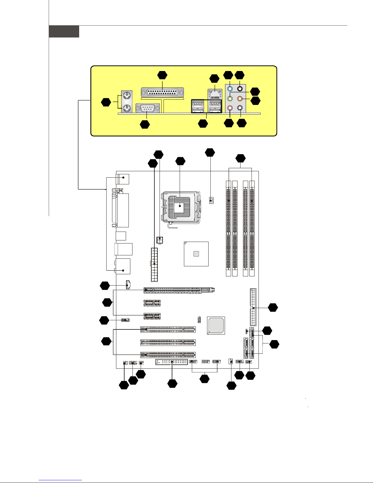
Layout of P965 Neo Series
(MS-7235 v1.X) ATX Mainboard
Installation Guide
“ How to use this Installation Guide? ”
This installation guide is designed for you to easily install the mainboard. Follow the steps below to use this guide:
- Read the specifications of the mainboard first on page En-1.
- Find out the component with the component number at your desire from the layout of the mainboard on page En-2.
- Find out the component description and installing instructions with the “Components Index Table” direction and install
it.
- Set BIOS and install the driver / utiltity at your desire.
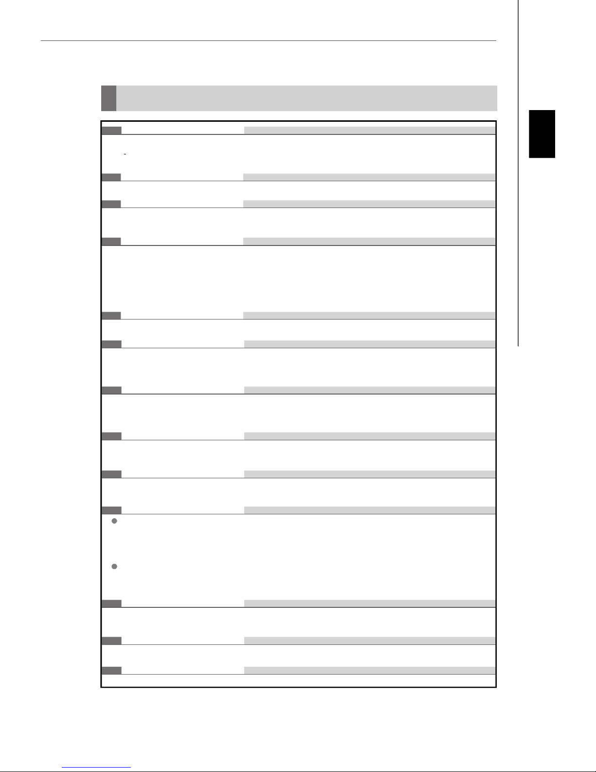
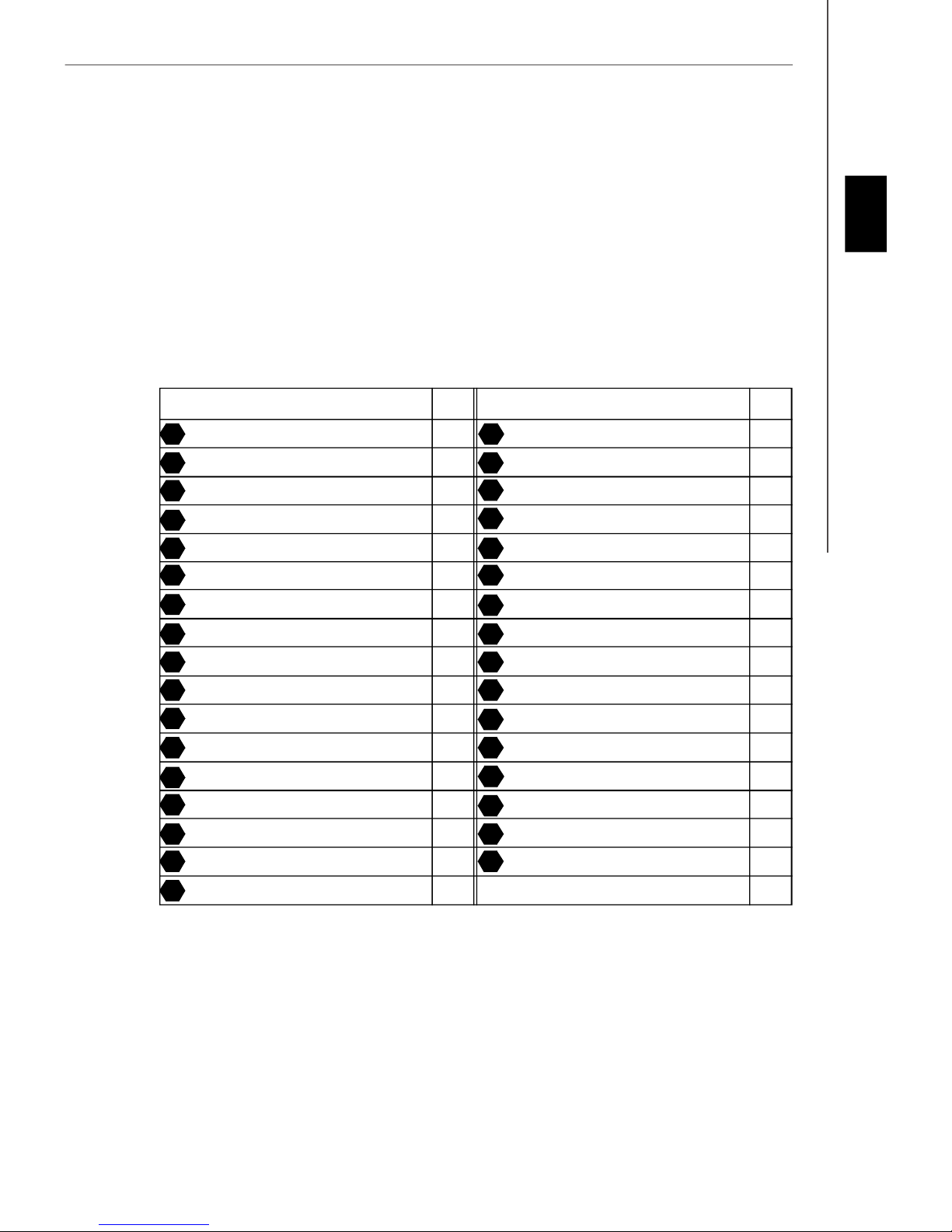
Components Index Table
Component Number Component Numberpage page
Central Processing Unit Socket En-4 DDRII Sockets : DIMM1~4 (dual channel)En-5
1
3
English
Fan Power Connectors En-6 Floppy Disk Driver Connector En-6
4
ATA 100 Hard Disk Connector En-6 Serial ATA Connector En-6
6
Front Panel Connectors En-7 Front USB 2.0 Connector En-7
8
IEEE 1394 Connector En-7 Front Panel Audio Connector En-8
10
14 15
CD-In Connector En-8 Chassis Intrusion Switch Connector En-8
16
IrDA Infrared Module Connector En-8 D-BracketTM 2 Connector En-9
Clear CMOS Button En-10 ATX 24-Pin Power Connector En-10
20
ATX 12V Power Connector (2x2-Pin) En-10 ATX 12V Power Connector (1x4-Pin) En-10
23
26
PCI Express Slot (x16/ x4/ x1) En-11 PCI Slot En-11
29
Mouse/ Keyboard port Connector En-12 Parallel Port Connector En-12
Serial Port Connector En-12 IEEE 1394 Port Connector En-12
31 34
LAN (RJ-45) Jack En-13 USB Connectors En-13
35
37
Green Audio Jack (Line-out) En-13 Blue Audio Jack En-13
Pink Audio Jack (Mic-In) En-13 Orange Audio Jack En-13
39
41 42
Black Audio Jack (Rear Surround-Out) En-13 Gray Audio Jack (Side Surround-Out) En-13
43
Coaxial S/PDIF-out Connector En-13
5
7
9
12
19
21
25
27
30
36
38
40
En-3

MS-7235 Mainboard
Central Processing Unit: CPU
1
The mainboard supports Intel® processor. The mainboard uses a CPU socket called Socket-775 for easy CPU
installation.
For the latest information about CPU, please visit http://www.msi.com.tw/program/products/mainboard/mbd/
pro_mbd_cpu_support.php.
Important
Overheating
Overheating will seriously damage the CPU and system, always make sure the cooling fan can work properly to protect
the CPU from overheating.
Replacing the CPU
While replacing the CPU, always turn off the ATX power supply or unplug the power supply’s power cord from grounded
outlet first to ensure the safety of CPU.
CPU & Cooler Installation Procedures for Socket 775
1. The CPU socket has a plastic cap on it to protect the contact from damage. Before you have installed
the CPU, always cover it to protect the socket pin.
2. Remove the cap from lever hinge side.
3. The pins of socket reveal.
4. Open the load lever.
5. Lift the load lever up and open the load plate.
6. After confirming the CPU direction for correct mating, put down the CPU in the socket housing
frame. Be sure to grasp on the edge of the CPU base. Note that the alignment keys are matched.
7. Visually inspect if the CPU is seated well into the socket. If not, take out the CPU with pure vertical
motion and reinstall.
8. Cover the load plate onto the package.
9. Press down the load lever lightly onto the load plate, and then secure the lever with the hook under
retention tab.
10.Align the holes on the mainboard with the cooler. Push down the cooler until its four clips get
wedged into the holes of the mainboard.
11.Press the four hooks down to fasten the cooler. Then rotate the locking switch (refer to the correct
direction marked on it) to lock the hooks.
12.Turn over the mainboard to confirm that the clip-ends are correctly inserted.
Important
alignment key
1.Check the information in BIOS for the CPU temperature.
2. Whenever CPU is not installed, always protect your CPU socket pin with the plastic cap covered to avoid damaging.
3. Please note that the mating/unmating durability of the CPU is 20 cycles. Therefore we suggest you do not plug/unplug
the CPU too often.
En-4
Installation Guide
Memory
2
DDR
Specification : 184-pin, 2.5v.
Single channel definition : All DIMM slots are GREEN color.
Dual channels definition : DIMM slot(s) on Channel A are marked in GREEN color. DIMM slot(s) on Channel B are
3
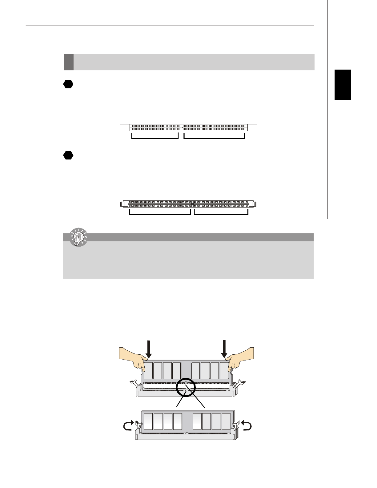
DDRII
Specification : 240-pin, 1.8v.
Single channel definition : All DIMM slots are GREEN color.
Dual channels definition : DIMM slot(s) on Channel A are marked in GREEN color. DIMM slot(s) on Channel B are
marked in Purple color.
40x2=80 pin 52x2=104 pin
marked in Orange color.
English
64x2=128 pin 56x2=112 pin
Important
-DDRII modules are not interchangeable with DDR and the DDRII standard is not backward compatible, you should
always install DDRII memory module in the DDRII DIMM slot and install DDR memory module in the DDR DIMM slot.
- In dual-channel mode, make sure that you install memory modules of the same type and density in different
channel DDR DIMM slots.
- To enable successful system boot-up, always insert the memory modules into the DIMM1 first.
Installing DDR/ DDRII Modules
You can find the notch on the memory modules and the volt on the DIMM slots whether DDR or DDRII. Follow the procedures
below to install the DDR/ DDRII module properly.
1. The DDR/DDRII modules has only one notch on the center of module. The module will only fit in the right orientation.
2. Insert the memory module vertically into the DIMM slot. Then push it in until the golden finger on the memory module
is deeply inserted in the socket.
3. The plastic clip at each side of the DIMM slot will automatically close.
Volt
Notch
En-5
MS-7235 Mainboard
Connectors, Jumper, Slots
4
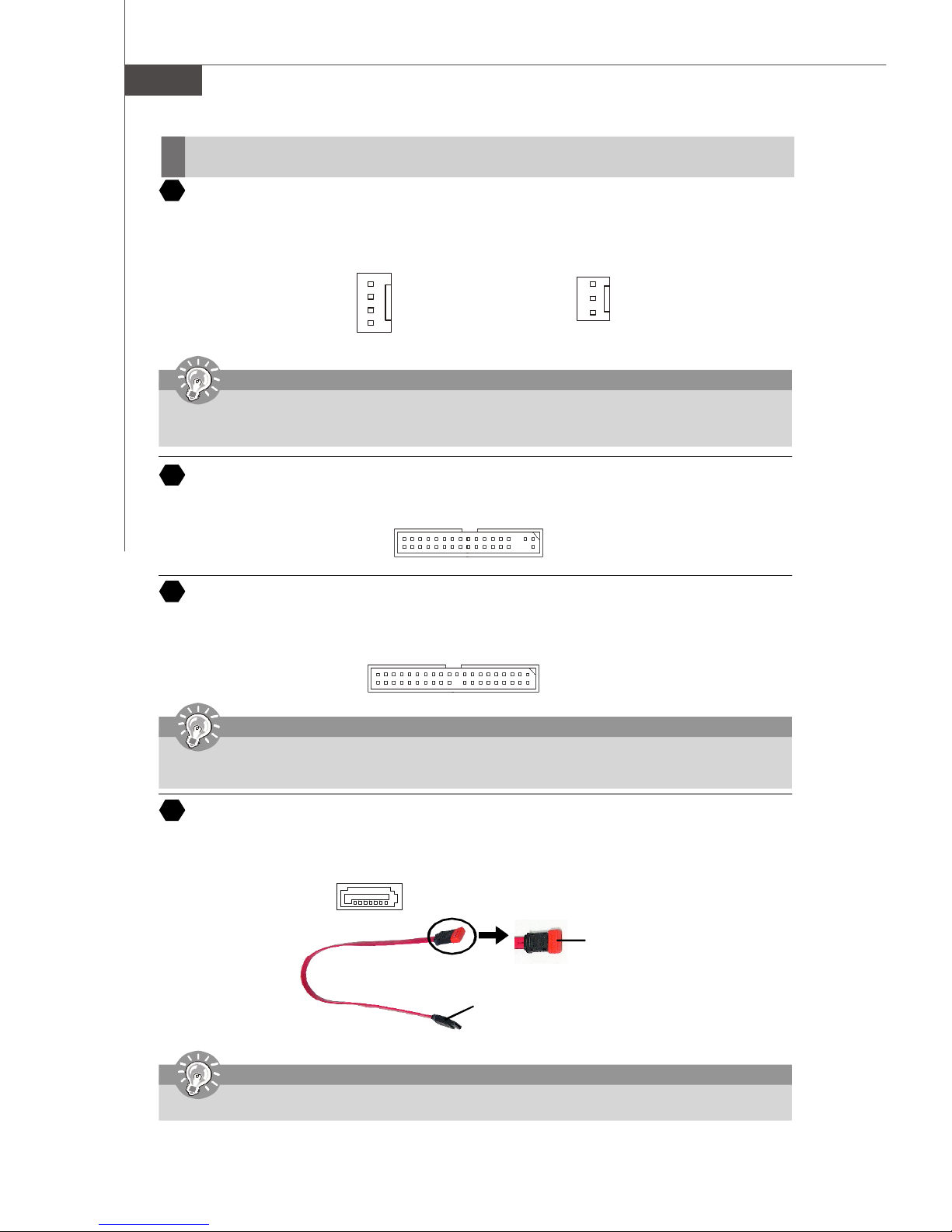
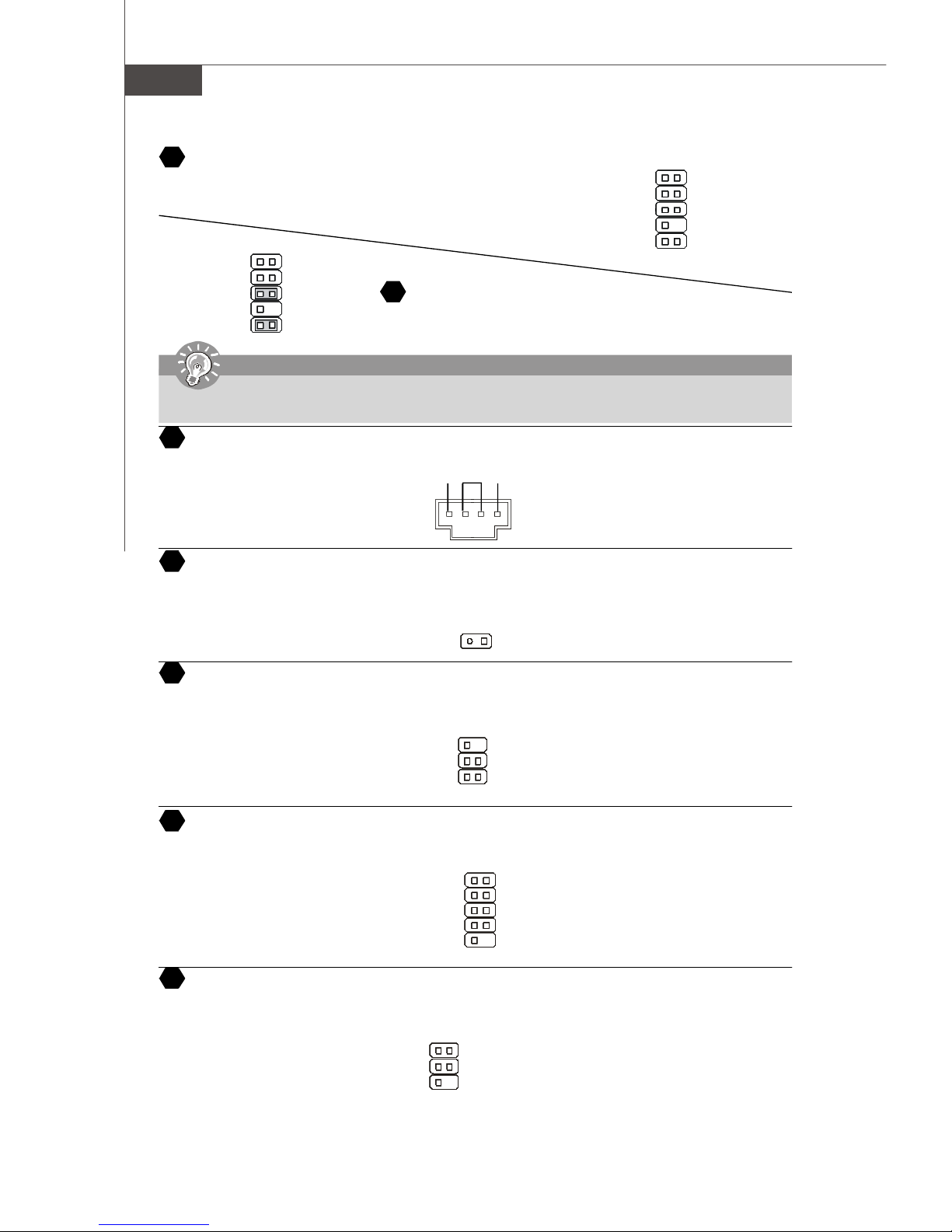
Fan Power Connectors
The fan power connectors support system cooling fan with +12V. The CPUFAN1 supports Smart FAN function. When
connect the wire to the connectors, always take note that the red wire is the positive and should be connected to the +12V,
the black wire is Ground and should be connected to GND. If the mainboard has a System Hardware Monitor chipset onboard, you must use a specially designed fan with speed sensor to take advantage of the fan control.
Control
SENSOR
+12V
GND
CPU FAN
Important
Please refer to the recommended CPU fans at Intel® official website or consult the vendors for proper CPU cooling fan.
Fan/heatsink with 3 or 4 pins are both available for CPUFAN. Please note that only install 4 pins FAN/heatsink support
Smart FAN.
5
Floppy Disk Drive Connector (FDD connector)
The mainboard provides a standard floppy disk drive connector that supports 360K, 720K, 1.2M, 1.44M and 2.88M floppy
disk types.
6
ATA Hard Disk Connector (IDE connector)
A IDE connector can connect a Master and a Slave drive. You can connect CD-ROM/ Hard Driver and other IDE devices.
The Ultra ATA interface boosts data transfer rates between the computer and the hard drive up to 100 megabytes (MB) per
second.
Important
SENSOR or NC
+12V
GND
SYS FAN/ NBFAN/
POWER FAN
If you install two hard disks on cable, you must configure the second drive to Slave mode by setting its jumper. Refer
to the hard disk documentation supplied by hard disk vendors for jumper setting instructions.
Serial ATA Connector
7
SATA connector supports serial ATA data rates of 150 MB/s and will be marked in ORANGE color. SATAII connector
supports serial ATA data rates of 300 MB/s and will be marked in PURPLE/BLUE color. Each SATA connector can connect
to 1 hard disk device.
SATA connector (Orange)
SATAII connector (Purple/Blue)
Serial ATA cable
Connect to SATA connector
Important
Please do not fold the Serial ATA cable into 90-degree angle. Otherwise, data loss may occur during transmission.
Take out the dust cover and connect
to the hard disk devices
En-6
Installation Guide
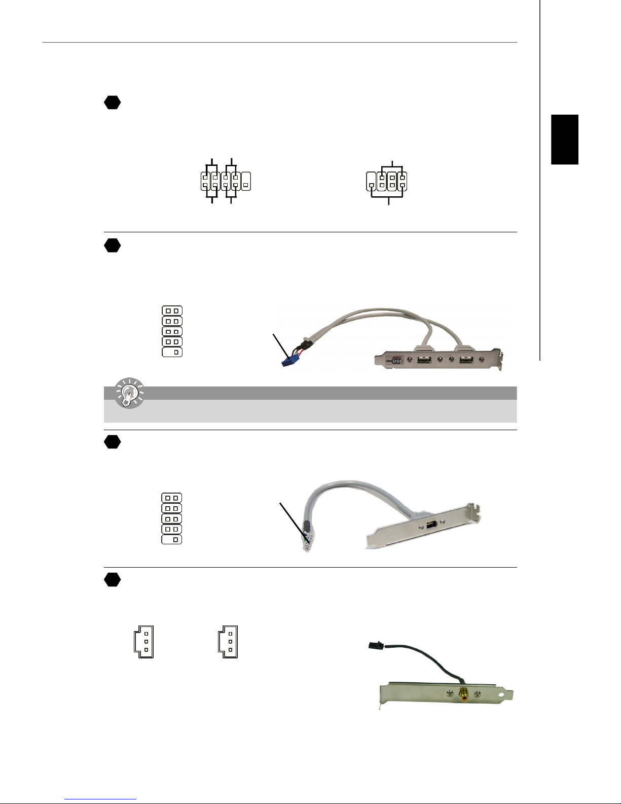
8
Front Panel Connectors
These two front panel connectors are used for electrical connection to the front panel switches and LEDs. JFP1 is compliant
with Intel® Front Panel I/O Connectivity Design Guide.
Power
Power
LED
Switch
Power LED
English
JFP1
9
Front USB 2.0 Connector (Yellow)
USB 2.0 technology increases data transfer rate up to a maximum throughput of 480Mbps, which is 40 times faster than
USB 1.1, and is ideal for connecting high-speed USB interface peripherals such as USB HDD, digital cameras, MP3
players, printers, modems and the like.
1 2
VCC
USB0-
USB0+
GND
Key (no pin)
9
Important
Note that the pins of VCC and GND must be connected correctly to avoid possible damage.
10
IEEE 1394 Connectors (Green)
The 1394 pin header allows you to connect IEEE 1394 ports via an external IEEE1394 bracket.
2
1
HDD
LED
VCC
USB1USB1+
GND
USBOC
10
10
9
Reset
Switch
Connected to USB
connector
7
8
Speaker
1
JFP2
2
USB 2.0 Bracket
(Optional)
Connected to 1394
1 2
TPA+
Ground
TPB+
Cable power
Key (no pin)
11
SPDIF-Out Connector/ SPDIF-In Connector
These two connectors are used to connect SPDIF (Sony & Philips Digital Interconnect Format) interface for digital audio
transmission.
SPDIF_Out
TPAGround
TPBCable power
Ground
9 10
GND
SPDIF_out
VCC
connector (with foolproof design)
GND
SPDIF_in
VCC
SPDIF_In
Connected to SPDIF-out/
SPDIF-in connector
SPDIF Bracket (Optional)
IEEE1394 Bracket
(Optional)
En-7
MS-7235 Mainboard
12
Front Panel Audio Connector
The front panel audio connector allows you to connect to the front panel audio and
is compliant with Intel® Front Panel I/O Connectivity Design Guide.
2
1
AUD_MIC
AUD_MIC_BIAS
AUD_FPout_R
HP_ON
AUD_FPout_L
Important
If you do not want to connect to the front audio header, pins 5 & 6, 9 & 10 have to be jumpered in order to have signal output
directed to the rear audio ports. Otherwise, the Line-Out connector on the back panel will not function.
CD-In Connector
14
This connector is provided for CD-ROM audio.
AUD_GND
AUD_VCC
AUD_RET_R
Key
AUD_RET_L
910
Front Panel Audio Connector
13
The front panel audio connector allows you to connect to the front panel
audio and is compliant with Intel® Front Panel I/O Connectivity Design Guide.
GND R
L
port1 _L
port1 _R
port2_R
Sense_Send
port2_L
2
1
Ground
Presence#
Sense1_Return
Key
Sense2_Return
910
15
Chassis Intrusion Switch Connector
This connector is connected to a 2-pin chassis switch. If the chassis is opened, the switch will be short. The system will
record this status and show a warning message on the screen. To clear the warning, you must enter the BIOS utility and
clear the record.
Ground
IrDA Infrared Module Connector
16
The connector allows you to connect to IrDA Infrared module. You must configure the setting through the BIOS setup to use
the IR function. It is compliant with Intel® Front Panel I/O Connectivity Design Guide.
VCC5
IRTX
17
Serial Port Header
The 9-pin header allows you to connect serial port via an external COM port bracket.
SOUT
Ground
18
TV-Out Connector
The TV-Out connector is for you to attach a TV-Out bracket. The TV-Out bracket offers some types of TV-Out connectors.
Select the appropriate one to connect to an television and it will be able to display PC information.
1 4
Ground
Yout
Cout
3
1
2
2
1
NC
6
5
156
DCD
SIN
DTR
COMP or CVBS
Ground (5)
CINTRU
NC
Ground
IRRX
DSR
RTS
CTS
RI (9)
En-8
Installation Guide
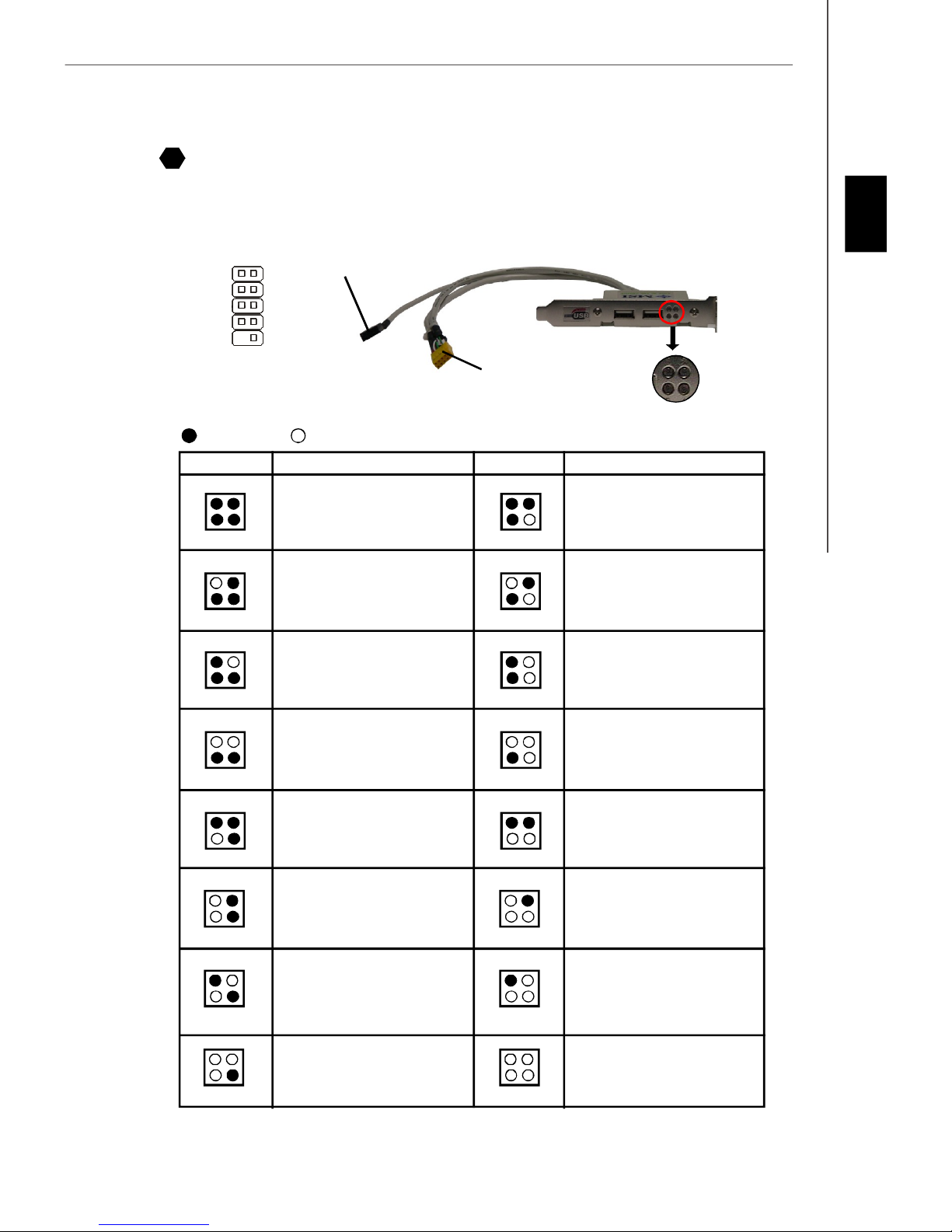
D-Bracket™ 2 Connector
19
The connector is for you to connect D-Bracket™ 2. D-Bracket™ 2 is a external USB Bracket that support both USB1.1 &
2.0 spec. It integrates four LEDs and allows users to identify system problem through 16 various combinations of LED
signals. The 4 LEDs can debug all problems that fail the system, such as VGA, RAM or other failures. This special feature
is very useful for the overclocking users. These users can use the feature to detect if there are any problems or failures.
English
2
1
DBG1
DBG1
DBG3
DBG4
Key
10
9
Red
LEDs signal
1 2
3 4
1 2
3 4
1 2
3 4
Connected to D-Bracket™
DBR1
DBR2
DBR3
DBR4
NC
2 Connector
Connected to the USB pinheader
in YELLOW color
Green
Description
System Power ON
The D-LED will hang here if the
processor is damaged or not installed properly.
Early Chipset Initialization
Memory Detection Test
Testing onboard memory size. The
D-LED will hang if the memory module is damaged or not installed
properly.
1 2
3 4
1 2
3 4
1 2
3 4
D-Bracket™ 2
(Optional)
1 2
3 4
DescriptionLEDs signal
Initializing Video Interface
This will start detecting CPU clock,
checking type of video onboard. Then,
detect and initialize the video adapter.
BIOS Sign On
This will start showing information
about logo, processor brand name,
etc...
Testing Base and Extended Memory
Testing base memory from 240K to
640K and extended memory above
1MB using various patterns.
LEDs
1 2
3 4
1 2
3 4
1 2
3 4
1 2
3 4
1 2
3 4
Decompressing BIOS image to RAM
for fast booting.
Initializing Keyboard Controller.
Testing VGA BIOS
This will start writing VGA sign-on
message to the screen.
Processor Initialization
This will show information regarding
the processor (like brand name, system bus, etc...)
Testing RTC (Real Time Clock)
1 2
3 4
1 2
3 4
1 2
3 4
1 2
3 4
1 2
3 4
Assign Resources to all ISA.
Initializing Hard Drive Controller
This will initialize IDE drive and
controller.
Initializing Floppy Drive Controller
This will initialize Floppy Drive and
controller.
Boot Attempt
This will set low stack and boot via
INT 19h.
Operating System Booting
En-9
 Loading...